about HBC-series electronic speed controllers for - MGM COMPRO ...
about HBC-series electronic speed controllers for - MGM COMPRO ...
about HBC-series electronic speed controllers for - MGM COMPRO ...

Create successful ePaper yourself
Turn your PDF publications into a flip-book with our unique Google optimized e-Paper software.
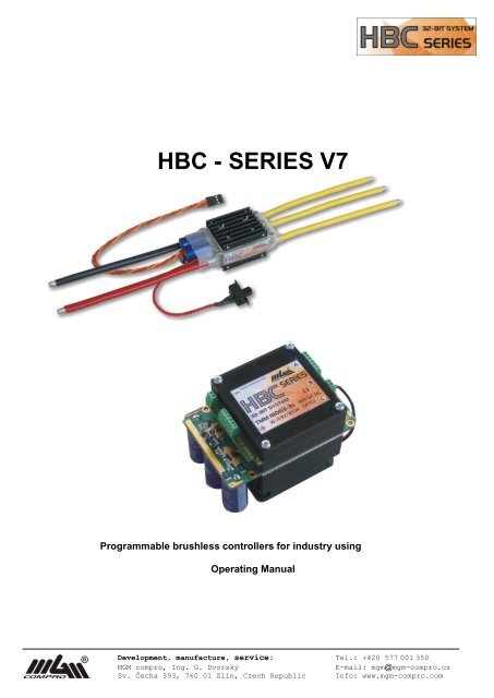
<strong>HBC</strong> - SERIES V7<br />
Programmable brushless <strong>controllers</strong> <strong>for</strong> industry using<br />
Operating Manual<br />
Development, manufacture, service: Tel.: +420 577 001 350<br />
<strong>MGM</strong> compro, Ing. G. Dvorský E-mail: mgm@mgm-compro.cz<br />
Sv. Čecha 593, 760 01 Zlín, Czech Republic Info: www.mgm-compro.com
Programmable "brushless“ <strong>controllers</strong> <strong>for</strong> industry<br />
TMM ® xxxx – 3 <strong>HBC</strong>-<strong>series</strong> V7 (Version 7.xx)<br />
2 / 68 <strong>HBC</strong>-<strong>series</strong> V7<br />
Controllers TMM ® xxxx – 3 <strong>HBC</strong>-<strong>series</strong> V7 are designed to control sensor and sensorless BLDC motors in industrial and other applications.<br />
Both types are offered with cooling by vent or without it (cooled by airflow), in an enclosed or open design, also possibly with<br />
increased resistance to water and humidity (<strong>electronic</strong>s is coated with special coating/sealing). For options of control and overview of<br />
possible modifications, please see the text below.<br />
Thanks to a wide range of control possibilities, working voltages and supplied currents, as well as very small dimensions and compact<br />
layout it is suitable <strong>for</strong> a variety of industries and appliances. They feature very advanced (state-of-the-art) algorithms of motor control<br />
as well as safety of operation. Controller concept is based on a long experience with control of both sensorless and sensor BLDC motors<br />
in very heavy and demanding operating conditions.<br />
HW lay-out as well as controller’s features (behavior) may be customer defined to a great extent <strong>for</strong> this range of <strong>controllers</strong>. Wide<br />
range of customer set standard parameters are available. Parameters may be set using a PC in the programming (setting) mode of the<br />
controller or using control/communications line even during the controller operation or parameters may be set from manufacture according<br />
to customer requirements. Controller control is chosen during such settings from a wide range of possibilities, as well as many<br />
functions, inputs, outputs etc.<br />
Controller may be tailored to suit even very specific customer needs which are out of the range of the offered standard settings.<br />
To enable our customers to exploit the newest developments and satisfy new requirements, SW update of the PC programs as well as<br />
the firmware update of the controller can be carried out by the customer himself/herself though the internet at any time.<br />
New features of the <strong>HBC</strong>-<strong>series</strong> <strong>controllers</strong>:<br />
new - The <strong>controllers</strong> use new and very powerful 32 bit processors, which have enough throughput to satisfy all requirements and<br />
demands. That is also one of the reasons that these <strong>controllers</strong> have features and possibilities not achievable with simple <strong>controllers</strong><br />
using 8-bit or even 16-bit processors.<br />
new - Controllers offer up to 400A / 63V (= 15 Lipol), that is up to 25kW!<br />
new - Choice of the controlling type (airplane, car, boat, heli – PWM, constant rpm, constant torque) depends only on your controller<br />
settings, and both unidirectional as well as bidirectional operation is enabled (except <strong>for</strong> heli)<br />
new - Controllers have 4 memory banks <strong>for</strong> parameter settings � choice of one of the 4 preset settings is thus very easy<br />
new - Internal Black Box (logging device) is integrated into the controller<br />
new - the <strong>controllers</strong> can make use of „back data channel“ (telemetry) - real time telemetric data transfer from the model) of<br />
some RC sets (such as TWIN by MZK servis) and can there<strong>for</strong>e send all the measured values to the transmitter in real time<br />
(to a display unit connected to the transmitter)<br />
new - Controllers making use of the back channel have two servocables (one <strong>for</strong> control of the controller, second <strong>for</strong> the data<br />
transmission to the receiver) - it is also a great advantage that feeding of the receiver and servos is doubled in this case �<br />
higher safety and smaller losses on the resistors of the servocable and its connector<br />
new - Very clear indication of different states of the controller using 4 LED<br />
new - When connected to PC, both saved data as well as warning and error notifications are transferred from the controller to the<br />
PC<br />
new - Controller can send all the measured (logged) values into PC in real time (§NA)<br />
new - It is possible to reduce power <strong>for</strong> both reverse as well as <strong>for</strong>ward gear (current reduction to preset value)<br />
new - Powerful switched S-BEC, with choice of 5V and 6V or 5V, 6V, 7V and 8V (version HV-BEC), currents up to 6A<br />
new - For <strong>controllers</strong> up to 35V (i.e. up to 8 Lipol cells) is possible to choose BEC or optical coupling of driving PWM signal (OPTO<br />
version) in order<br />
new - Parallel to BEC is possible connect battery � significantly increase safety and reliability all RC system<br />
new - Extremely fine throttle step 2048 values (steps)<br />
new - Very high maximal motor revolutions (up to 250 000 rpm <strong>for</strong> a 2 pole motor)<br />
new - Automatic sensor setting when sensor motors are connected � the problematic "phasing" of sensors and phases on motor<br />
is there<strong>for</strong>e not needed, the sensor position is also optimized; it is possible to connect also other motors not just those recommended<br />
by EFRA<br />
new - Sensor motor <strong>controllers</strong> (marking SE) you can run with sensorless motors also – necessary only set correct motor type to parameters<br />
Further advantages <strong>HBC</strong>-<strong>series</strong> <strong>controllers</strong>:<br />
- very transparent and easy settings of parameters using PC with Windows (XP, Vista, 7)<br />
- you can update the controller with a newer firmware yourself from our website www.mgm-compro.cz, using your PC, USBCOM_4<br />
module and CC_11 cable. This new feature is very useful and favorable. Controller may have additional features that were not<br />
available at the time of purchase. You may have actual version at all times. The same components will be used to set parameters<br />
and read-out of data from the controller.<br />
- <strong>controllers</strong> support NiCd, NiMH, Lipol, Li-Ion, A123, acid (Pb) cells and possibly any other new battery type (universal settings)<br />
which may have not even existed at the time of the controller production or also with power supplies (more bellow)<br />
- unmatched protection and management of accumulators Lipol / Li-Ion (<strong>for</strong> these cell types this is of a fundamental importance) as<br />
well as A123 cells and NiCd / NiMH<br />
- very smooth starts with sensor as well as sensorless motors<br />
- Possibility to connect brake lights or flashing beacon, indication and outputs<br />
- They are standard manufacture in a version with a switch (in a safe connection – as in all <strong>MGM</strong> compro <strong>controllers</strong>, damage of<br />
switch does not affect controller)<br />
- it is possible to choose from several variants and cooling with active cooling and water cooling<br />
- it is possible to choose a variant with enhanced resistance to water and humidity (marked as WP) or with a 100% water resistance<br />
(marked as WR)
Table of content:<br />
3 / 68 <strong>HBC</strong>-<strong>series</strong> V7<br />
Table of content: ........................................................................................................................................... 3<br />
First steps. .................................................................................................................................................... 4<br />
Basic Recommendations. ............................................................................................................................. 4<br />
Technical data 1. (valid <strong>for</strong> 25°C environment temperature) ........................................................................ 5<br />
Technical data 2. (valid <strong>for</strong> 25°C environment temperature) ........................................................................ 6<br />
Optional Accessories. ................................................................................................................................... 6<br />
Available versions of <strong>HBC</strong>-<strong>series</strong> TMM xxxxx-3 V7. ................................................................................... 7<br />
Basic description of the <strong>controllers</strong> 1. ......................................................................................................... 14<br />
Summary of possible inputs / outputs 1 ...................................................................................................... 14<br />
Basic description of the <strong>controllers</strong> 2. ......................................................................................................... 15<br />
Summary of possible inputs / outputs 2 ...................................................................................................... 16<br />
Marking and Specification of the <strong>HBC</strong> <strong>controllers</strong>. ..................................................................................... 21<br />
Switching BEC: S-BEC, HV-BEC. ............................................................................................................. 24<br />
Basic controller connection. ........................................................................................................................ 25<br />
Emergency disconnection circuit. ............................................................................................................... 26<br />
Connecting controller to the traction supply and turning on. ...................................................................... 28<br />
Driving signals specification ........................................................................................................................ 29<br />
Driving signal – correct limits and emergency conditions. .......................................................................... 31<br />
Back data transfer, telemetry (only <strong>for</strong> <strong>controllers</strong> marking „BC―). ............................................................. 33<br />
Sensor motors and <strong>controllers</strong> („SE― marking). .......................................................................................... 35<br />
Automatic sensor setting procedure. .......................................................................................................... 36<br />
Basic operational modes – mode select and driving type A. ...................................................................... 37<br />
Memory select. ............................................................................................................................................ 37<br />
SECURITY WARNING: .............................................................................................................................. 38<br />
Programming of the parameters. ................................................................................................................ 38<br />
Parameters description. .............................................................................................................................. 41<br />
Parameters setting / Data reading from controller. ..................................................................................... 48<br />
Internal Black Box (flying recorder) ............................................................................................................. 50<br />
Throttle limits setting (range of driving signal). ........................................................................................... 53<br />
Start with automatic throttle limits. .............................................................................................................. 55<br />
Start with programmed throttle limits. ......................................................................................................... 56<br />
Maximal revolution of the rotor Settings. .................................................................................................... 57<br />
HELI modes. ............................................................................................................................................... 58<br />
Update SW inside the controller (firmware). ............................................................................................... 60<br />
Installation and run program Controller 2. .................................................................................................. 61<br />
Update of program Controller 2 .................................................................................................................. 61<br />
Controller states indication, Error messages. ............................................................................................. 62<br />
Sparking prevent when connect higher voltage. ......................................................................................... 63<br />
Additional in<strong>for</strong>mation. ................................................................................................................................ 64<br />
Protective and safety mechanisms of TMM ® <strong>controllers</strong>. ........................................................................... 65<br />
Accessories. ................................................................................................................................................ 66<br />
Content of delivery. ..................................................................................................................................... 68<br />
Product Warranty. ...................................................................................................................................... 68<br />
Service and Technical Support ................................................................................................................... 68<br />
Note:<br />
Content…………….. all items are available quickly by CTRL+ left mouse button.<br />
blue underlined ….. all like this marking texts in manual quickly jump, by CTRL+ left mouse button, to corresponding content (cross<br />
reference).<br />
In the Manual in „pdf― <strong>for</strong>mat on these marking texts standard cursor changed to hand symbol ( ) . In this case only click to left<br />
mouse button, (without CTRL), caused jump to corresponding content (cross reference).<br />
(§NA) ……………….. parameters or features parking by this symbol are not available in this moment. As soon as will be available,<br />
you can download and update new firmware <strong>for</strong> your controller – please watch in<strong>for</strong>mation on our web.<br />
In this manual are described general things <strong>about</strong> this line <strong>controllers</strong>. Exceptions <strong>for</strong> each type of model are described in separate<br />
chapters or differences are highlights.<br />
Separate chapters are devote to technical specifications and related things.<br />
Development, manufacture, service: Tel.: +420 577 001 350<br />
<strong>MGM</strong> compro, Ing. G. Dvorský E-mail: mgm@mgm-compro.cz<br />
Sv. Čecha 593, 760 01 Zlín, Czech Republic Info: www.mgm-compro.com
First steps.<br />
4 / 68 <strong>HBC</strong>-<strong>series</strong> V7<br />
First, be<strong>for</strong>e you start run controller, we recommend read Basic Recommendations and make these steps:<br />
� solder corresponding connectors<br />
� select basic of driving type (car, boat, aircraft or helicopter). This you make by program „Controller 2―<br />
� connect controller to driving (master) system, see more Controller’s connection.<br />
� When you want use sensor motor, read first instruction here: Sensor motor settings<br />
For first tests you can use controller with pre-defined average value of all parameters <strong>for</strong> basic type of driving types (type cells = Automat 78%)<br />
and Start with Automatic throttle limits.<br />
Of course, optimal behaviors of the controller and your system you achieve only by correct setting and tuning corresponding parameters.<br />
Parameter setting by program „Controller 2― is very simple and intuitive and enable easy and transparent setting all controller features <strong>for</strong> optimal<br />
behavior. If you wish to enjoy all the possibilities of the controller, please refer to the whole manual.<br />
When you set parameters, include throttle limits (= programed) or range of driving signal or driving voltage, you can start � Start with programed<br />
throttle limits.<br />
Basic Recommendations.<br />
� !!! Shorten the cables between the battery and the controller as much as possible (however not under 3 cm, there is a possibility of unsoldering<br />
wires from the controller) ! The higher the power and the "faster" the used motor, the more important is this requirement !<br />
� If you need to prolong the power conductors to batteries (distance between the controller and the batteries > 20 cm), it is necessary to<br />
solder additional capacitors (same as in the controller) as close to the controller (to ―+‖ and ―– ― conductors of the controller) as possible.<br />
The capacitors must be ―very low ESR", 105°C with at least double the capacity than those used in the <strong>controllers</strong>.<br />
It is strongly discouraged to prolong the overall length of conductors between the battery and the controller above 15 – 20 cm <strong>for</strong><br />
currents above 80A. If this is necessary <strong>for</strong> whatever cause, you must use cables with higher cross section (10mm 2 or more) and<br />
also capacitors block (i.e. many times more capacitors than used inside controller) !!!<br />
� !!! Use only quality and well dimensioned connectors <strong>for</strong> connect battery to the controller ! Very suitable and very reliable connectors<br />
are MP JET 2.5 – 3.5 – 5.5 – 6.0 mm, which are dimensioned <strong>for</strong> currents up to 200 – 300A, see more to file, Be careful when choosing<br />
power connectors <strong>for</strong> batteries and motor! on our www. MP JET connectors feature small transition resistance, small dimensions and very<br />
firm connection (they do not come apart themselves as some other types do). We recommend to put the socket on the ―– ― wire (black wire)<br />
of the controller and the plug on the ―+‖ wire (red wire).<br />
Connectors of „plug" type 4mm, even golden-plated (4mm Gold Plated Bullet Connectors) or connectors of „Dean“ type are discouraged<br />
<strong>for</strong> use.<br />
� !!! NOTICE, reversal of battery poles will reliably destroy the controller ! (The damage however, may not show immediately, but in some<br />
later runs !) There<strong>for</strong>e we recommend to put the socket on the ―– ― wire (black wire) of the controller and the plug on the ―+‖ wire (red wire)<br />
– not the same part <strong>for</strong> „+― and also „–― pole � possibility of reversal input voltage polarity is smaller.<br />
� Never connect more cells (higher voltage) than is specified in technical data, you can damage controller.<br />
� When you use more than 4 Lipol cells (more than ca 16V), use „antispark― resistor <strong>for</strong> first battery connection, see here: Sparking prevent<br />
when connect higher voltage.<br />
� The leads to the motor (wires marked “A”, “B”, ”C”) should be soldered directly to the motor or it is also possible to use the connectors mentioned<br />
above. If you decide to use connectors, this time solder sockets to the controller leads.<br />
Short circuit of these wires together (when batteries are connected) or short cut of these wires to the feeding voltage results in<br />
damage or destroy of the controller !<br />
� Short circuit motor cables or feeding cables to any other wires (driving signal, BEC, …) caused damaging of the controller.<br />
� Insulate the connectors after soldering, e.g. using heat shrinking sleeve.<br />
� !!! Using of power supplies <strong>for</strong> controller feeding is strictly prohibited ! Only battery <strong>for</strong> feeding is permit. If is necessary feed controller<br />
from power supply (i.e. not from the battery), braking is prohibited !!! as well as switch-off freewheel !!! If necessary braking<br />
in this case, you must use braking resistors with corresponding driving !!! (control signal <strong>for</strong> braking resistors controlling provide<br />
controller yourself). When braking without connected braking resistors, damaging of rthe controller is nearly certain.<br />
� !!! Do not SWITCH OFF controller or PLUG OFF BATTERY when motor RUN or when it is still turning – that may lead to damage or<br />
destroy of the controller !!! This also applies to spontaneous disconnecting of the connector during operation, e.g. by vibrations!!!<br />
This is why connectors should be chosen very carefully – see recommendation above.<br />
� !!! Be careful <strong>for</strong> using damaged motor or motor overloading, controller damaging is possible.<br />
� One controller can control only one motor.<br />
� It is necessary to cool the controller in operation with flowing air. Do not obstruct the access of cooling airflow to the controller,<br />
e.g. by packing the controller in foam, especially when working near its limit parameters or choose types with external coolers (possibly<br />
also with a fan).<br />
� It is recommended to measure current drawn from battery with charged battery and full load. Only clamp Ampermeters using is permitted<br />
(always <strong>for</strong> DC current, on the battery cables).<br />
Never use Ampermeter inserted to the circuit (i.e. between battery and controller) – you can damage controller !<br />
It is convenient to use measurements carried out by the controller during the drive and their display using PC. Please remember,<br />
that even one additional cog on pinion of the motor significantly increase the drawn currents. With acceleration set faster, currents in the<br />
start-up peak rise very fast, and that up to many times of the current in the steady state. It is necessary to do the measurement with the<br />
hardest batteries, which you wish to use in the set. This will prevent possible problems with overloading the controller, motor and batteries.<br />
� Receiver and antenna should be placed as far as possible from the controller, the motor, the batteries and power leads.<br />
� Controllers designed <strong>for</strong> sensor motors (SE) can working also with sensorless motors – depend only on the parameter settings.
5 / 68 <strong>HBC</strong>-<strong>series</strong> V7<br />
Technical data 1. (valid <strong>for</strong> 25°C environment temperature)<br />
(valid <strong>for</strong> smaller types of the <strong>controllers</strong>, up to 6,3 kW)<br />
Temperature of the environment: 0°C to 40°C Number of regulation steps: 2048 / full throttle range<br />
Motor controlling: PWM: from 8 up to 32 kHz Max. rpm <strong>for</strong> 2 poles motor: 250 000 rpm<br />
Suitable <strong>for</strong> motors: 2 to 40 pole motors of classical conception (rotor inside) and also <strong>for</strong> outrunners (rotor is on the outer side)<br />
(sensors + sensorless) FreeAir, Hacker, Kontronik, Lehner, Mega AC, Model Motors, MP JET, MVVS, Neu, PJS, Plettenberg, Überall model, etc.<br />
Control signal: Positive pulses 1.5 � 0,8 ms, period 3.5 up to 30 ms / voltage 0 – 3.3V (5.0V) / logic signal / data transfer<br />
S-BEC (switching BEC) : 5V, 6V / 2A cont., 6A max. (10 sec.), input voltage = 6 up to 35V by type (OPTO versions haven’t BEC !)<br />
HV-BEC (switching BEC) : 5V, 6V, 7V, 8V / 2A cont, 6A max. (10 sec.), input voltage = 6 up to 35V by type (OPTO versions haven’t BEC !)<br />
Feeding: from batteries: NiCd, NiMH, Li-Ion, Li-Pol, A123, acid (Pb) or others cells<br />
from power supplies – in this case not permit braking without braking resistors ! or switch-of freewheel !<br />
Servocables: with JR gold connectors, 20 cm long, 0.25mm 2<br />
Weight is defined <strong>for</strong> basic modification, i.e. internal cooling plate, shrinking tube, WP, OPTO, input PWM driving (servocable #1), without switch.<br />
In case of use additional parts as external hetasinks, fans, … weight increase :<br />
dimension HT (ribbed heatsink) : +3,5 mm +7,5 gram (single heatsink = 37,5 ×31×5 mm / 11 gram), take off internal cooling plate<br />
dimension HTW (1× water cooler) : +9 mm +16,5 gram (single heatsink = 37,5 ×31×6 mm / 15 gram, pipes Ø 4 / Ø 3, length13 mm )<br />
dimension HTW (2× water cooler) : +6 mm +15 gram<br />
dimension F (fan) : +10 mm +10 gram (30 × 30 × 10 mm / include screws / 10 gram)<br />
switch (with wire) : + 2 gram<br />
servocable #2 - #5 (each one) : + 3,2 gram<br />
S-BEC, HV-BEC : + 3 gram<br />
Note: by shortening of power cables to motor and battery (power supply) weight decrease proportionally.<br />
Marking in program ―Contreoller 2‖ (6026-3) (8026-3) (12026-3) (16026-3) (28026-3)<br />
<strong>HBC</strong>-<strong>series</strong> TMM ® xxxxx-3 V 7.xx 4526-3 6026-3 9026-3 12026-3 21026-3<br />
Maximal continuous power: 1,17 kW 1,56 kW 2,34 kW 3,12 kW 5,46 kW<br />
Basic dimensions see picture [mm]<br />
Dimension CL (Filtering capacitors) [mm]: Ø 8 × 17 Ø 8 × 17 Ø 10 × 17 Ø 10 × 17 Ø 10 × 17<br />
Dimension CT (Controller thickness) [mm]: 13 14 17 19 25<br />
Dimension D (M3 threads distance) [mm] *): -- -- 22 24 30<br />
Weight without power cables: 34 g 36 g 48 g 56 g 82 g<br />
Weight with power cables: 47 g 49 g 77 g 91 g 125 g<br />
Feeding voltage: 6 – 26 V 6 – 26 V 6 – 26 V 6 – 26 V 6 – 26 V<br />
No. of feeding cells NiCd / NiMH: 6 – 18 6 – 18 6 – 18 6 – 18 6 – 18<br />
No. of feeding cells Li-Ion / Li-Pol: 2 – 6 2 – 6 2 – 6 2 – 6 2 – 6<br />
No. of feeding cells A123: 3 – 7 3 – 7 3 – 7 3 – 7 3 – 7<br />
Max. continuous current: 45 A 60 A 90 A 120 A 210 A<br />
Max. continuous current (short time): 60 A 80 A 120 A 160 A 280 A<br />
Peak current <strong>for</strong> max. 5 seconds: 75 A 100 A 150 A 200 A 340 A<br />
On-state FET resistance at 25 °C: 2×0,8 m� 2×0,7 m� 2×0,4 m� 2×0,35 m� 2×0,18 m�<br />
Possible modification: BEC/OPTO BEC/OPTO BEC/OPTO BEC/OPTO BEC/OPTO<br />
Possible BEC version: S / HV S / HV S / HV S / HV S / HV<br />
Cables cross section to batt. ■■ / motor ■■■**):2,5/2,5 mm 2 2,5/2,5 mm 2<br />
4/4 mm 2<br />
6/4 mm 2<br />
6/4 mm 2<br />
Marking in program ―Contreoller 2‖ (7035-3) (14035-3) (25035-3) (6245-3) (12545-3) (7063-3) (14063-3)<br />
<strong>HBC</strong>-<strong>series</strong> TMM ® xxxxx-3 V 7.xx 5035-3 10035-3 18035-3 4545-3 9045-3 5063-3 10063-3<br />
Maximal continuous power: 1,75 kW 3,50 kW 6,30 kW 2,025 kW 4,05 kW 3,15 KW 6,30 kW<br />
Basic dimensions see picture [mm]<br />
Dimension CL (Filtering capacitors) [mm]: Ø 8 × 17 Ø 10 × 17 Ø 10 × 17 Ø 10 × 31 Ø 10 × 31 Ø 8 × 31 Ø 10 × 31<br />
Dimension CT (Controller thickness) [mm]: 14 19 25 19 25 13 17<br />
Dimension D (M3 threads distance) [mm] *): -- 24 30 24 30 -- 22<br />
Weight without power cables: 36 g 56 g 77 g 51 g 76 g 37 g 63 g<br />
Weight with power cables: 49 g 91 g 120 g 65 g 105 g 51 g 98 g<br />
Feeding voltage: 6 – 35 V 6 – 35 V 6 – 35 V 9 – 45 V 9 – 45 V 9 – 63 V 9 – 63 V<br />
No. of feeding cells NiCd / NiMH: 6 – 24 6 – 24 6 – 24 9 – 32 9 – 32 9 – 44 9 – 44<br />
No. of feeding cells Li-Ion / Li-Pol: 2 – 8 2 – 8 2 – 8 3 – 10 3 – 10 3 – 15 3 – 15<br />
No. of feeding cells A123: 3 – 9 3 – 9 3 – 9 4 – 12 4 – 12 4 – 17 4 – 17<br />
Max. continuous current: 50 A 100 A 180 A 45 A 90 A 50 A 100 A<br />
Max. continuous current (short time): 70 A 140 A 250 A 62 A 125 A 70 A 140 A<br />
Peak current <strong>for</strong> max. 5 seconds: 90 A 180 A 300 A 77 A 155 A 90 A 180 A<br />
On-state FET resistance at 25 °C: 2×1,1 m� 2×0,55 m� 2×0,28 m� 2×1,0 m� 2×0,50 m� 2×0,65 m� 2×0,33 m�<br />
Possible modification: BEC/OPTO BEC/OPTO BEC/OPTO OPTO OPTO OPTO OPTO<br />
Possible BEC version: S / HV S / HV S / HV -- -- -- --<br />
Cables cross section to batt. ■■ / motor ■■■**):2,5/2,5 mm 2 6/4 mm 2<br />
The appearance and the technical data may be changed without prior notice.<br />
6/4 mm 2<br />
*) Notice: available <strong>for</strong> <strong>controllers</strong> with two heatsinks<br />
**) Notice: possibly also 2×2.5 mm 2 or 2×4.0 mm 2 respectively 2×6,0 mm 2 upon request<br />
2,5/2,5 mm 2 4/4 mm 2<br />
2,5/2,5 mm 2<br />
Recommendations: If you use controller <strong>for</strong> currents higher than circa half of the maximal values, we do recommend intensive cooling by air flow or<br />
use of heat sinks (possibly also active cooling using fans or water cooling). This will not only prevent possible overheating of the<br />
controller, but you will also gain higher efficiency of the drive unit (cooler controller has lower losses than warm one).<br />
6/4 mm 2
6 / 68 <strong>HBC</strong>-<strong>series</strong> V7<br />
Technical data 2. (valid <strong>for</strong> 25°C environment temperature)<br />
(valid <strong>for</strong> higher types of the <strong>controllers</strong> > 6,3 kW)<br />
Temperature of the environment: 0°C to 40°C Number of regulation steps: 2048 / full throttle range<br />
Motor controlling: PWM: from 8 up to 32 kHz Max. rpm <strong>for</strong> 2 poles motor: 250 000 rpm<br />
Suitable <strong>for</strong> motors: 2 to 40 pole motors of classical conception (rotor inside) and also <strong>for</strong> outrunners (rotor is on the outer side)<br />
(sensors + sensorless) FreeAir, Hacker, Kontronik, Lehner, Mega AC, Model Motors, MP JET, MVVS, Neu, PJS, Plettenberg, Überall model, etc.<br />
Control signal: Positive pulses 1.5 � 0,8 ms, period 3.5 up to 30 ms / voltage 0 – 3.3V (5.0V) / logic signal / data transfer<br />
Feeding: from batteries: NiCd, NiMH, Li-Ion, Li-Pol, A123, acid (Pb) or others cells<br />
from power supplies – in this case not permit braking without braking resistors ! or switch-of freewheel !<br />
Servocables: with JR gold connectors, 20 cm long, 0.25mm 2<br />
Weight is defined <strong>for</strong> basic modification, i.e. ribbed heatsink, WP, OPTO, input PWM driving, without fan(s), without switch.<br />
In case of use additional parts as external hetasinks, fans, … weight and dimension increase .<br />
Marking in program ―Contreoller 2‖ (25063-3) (40063-3) (60063-3)<br />
<strong>HBC</strong>-<strong>series</strong> TMM ® xxxxx-3 V 7.xx 18063-3 25063-3 40063-3<br />
Maximal continuous power:<br />
Basic dimensions see pictures [mm]:<br />
11,34 kW 15,75 kW 25,2 kW<br />
Weight without power cables: 250 g 390 g ~3,0 kg<br />
Weight with power cables: depend on cables cross section and length<br />
Feeding voltage: 12 – 63 V 12 – 63 V 12 – 63 V<br />
No. of feeding cells NiCd / NiMH: 15 – 44 15 – 44 15 – 44<br />
No. of feeding cells Li-Ion / Li-Pol: 4 – 15 4 – 15 4 – 15<br />
No. of feeding cells A123: 5 – 17 5 – 17 5 – 17<br />
Max. continuous current: 180 A 250 A 400 A<br />
Max. continuous current (short time): 250 A 400 A 600 A<br />
Peak current <strong>for</strong> max. 5 seconds: 360 A 500 A 600 A<br />
On-state FET resistance at 25 °C: 2×0,8 m� 2×0,53 m� 2×0,4 m�<br />
Possible modification: OPTO OPTO OPTO<br />
Possible BEC version: -- -- --<br />
Cables cross section to batt. ■■ / motor ■■■ : 6/6 or 10/10 mm 2 *)<br />
10, 16 or 35 mm 2 35 - 120 mm 2<br />
*) Note: possibly also 16/16 mm 2 upon request The appearance and the technical data may be changed without prior notice<br />
Recommendations: If you use controller <strong>for</strong> currents higher than ca half of the maximal values, we do recommend intensive cooling by air flow or use<br />
of heat sinks (possibly also active cooling using fans or water cooling). This will not only prevent possible overheating of the controller,<br />
but you will also gain higher efficiency of the drive unit (cooler controller has lower losses than warm one).<br />
Note: Apparent discrepancy between controller’s marking and marking <strong>HBC</strong>-<strong>series</strong> is due to the fact that basic marking correspond with short time currents.<br />
Short time currents and peak currents are the same <strong>for</strong> <strong>HBC</strong>-<strong>series</strong> as well as <strong>for</strong> X-<strong>series</strong> <strong>controllers</strong>.<br />
Optional Accessories.<br />
You can specify all these options by your requersts in order. Basic possibilities are here, all possibilities are in the table „Possible specification ….―<br />
Switch (s): all <strong>controllers</strong> may be ordered with a switch (in a safe design - its damage or destroy does not affect the safety of flight and the<br />
model / motor don´t stop working when switch component damaged<br />
Heat sinks (coolers): For more efficient power loss (heat) dissipation, it is possible to optionally mount (from one, or both sides depending on the<br />
type of the controller) outer ribbed heat sinks (coolers) (<strong>controllers</strong> up to 6.3 kW). Controllers <strong>for</strong> higher power not possible<br />
order without heatsinks, they are included automatically in basic modifications.<br />
Fans: In case of insufficient cooling air flow it is possible to use heat sinks with fans FAN 05 (<strong>for</strong> <strong>controllers</strong> up to 6.3 kW), which significantly<br />
improve the cooling efficiency – active cooling.<br />
Possible order as set “FAN 05” separately, with screws, <strong>for</strong> additional mounting to heat sinks – using of another type<br />
is strictly prohibited !!!<br />
For <strong>controllers</strong> with power > 6.3 kW in case of insufficient cooling air flow it is possible to use heat sinks with fans FAN-12-60<br />
or FAN-12-50 (depend o type of ESC), which significantly improve the cooling efficiency – active cooling.<br />
Water cooling: version with water coolers is available <strong>for</strong> use in boats or in systems with higher demands <strong>for</strong> cooling intensity.<br />
Hydro version WP: water and humidity does not get on well with <strong>electronic</strong>s. For significant increase of durability of the controller against humidity<br />
and water, it is optionally possible to apply specialty protective cover (marked as WP). This however does not mean that the<br />
controller with this protection is 100% durable during humidity and water and that it is not necessary to protect it against these<br />
negative effects. The protection does not apply to salt water at all !<br />
Hydro version WR: If you need 100% protection against water, dirt, humidity, necessary choice WR modification. Plates with <strong>electronic</strong>s components<br />
are fully sealed in special matter, more expensive version. No possible repair ! The protection does not apply to salt<br />
water at all ! For more in<strong>for</strong>mation see manual “Water protection of RC equipment”.<br />
Sensor motors SE: all types of <strong>controllers</strong> may be ordered as „Sensor― – marked as SE. These <strong>controllers</strong> may be connected to sensorless motors<br />
as well as sensor motors. In case of sensor motors, types compatible with EFRA are recommended. (EFRA Handbook<br />
2007), e.g. motors „Velocity x.xR Brushless Motor― by Novak, etc., more see here ».<br />
Battery temperature BT: <strong>for</strong> OPTO versions of the <strong>controllers</strong> can add measuring of battery temperature<br />
Back data channel BC: all types of <strong>controllers</strong> may be ordered as version with telemetry, with additional servocable <strong>for</strong> connecting to ―back data<br />
channel‖ of receiver some of 2,4 GHz RC equipment, marking BC.<br />
BEC, HV BEC, OPTO: <strong>controllers</strong> up to 35V is possible order as OPTO with isolated input or with switching BEC, S-BEC (5V and 6V) or with switching<br />
BEC with ―high voltage output‖, HV-BEC with output voltage 5V, 6V, 7V and 8V, suitable <strong>for</strong> RC equipment working with<br />
supply voltage up to 8,4V (2×Lipol).<br />
Controllers <strong>for</strong> higher voltage than 35V are available only as OPTO, without BEC.
Available versions of <strong>HBC</strong>-<strong>series</strong> TMM xxxxx-3 V7.<br />
(specification in chapter „Technical data 1―)<br />
Basic dimensions.<br />
Dimensions CL, CT, HT1, HT2, D, F<br />
are in the table (Technical data)<br />
Regular controller without coolers,<br />
controlling by PWM, with switch<br />
4525-3, 6025-3, 5035-3, 5063-3<br />
Version with heat sinks <strong>for</strong> <strong>controllers</strong><br />
4525-3, 6025-3, 5035-3, 5063-3<br />
Version with 2 heat sinks <strong>for</strong><br />
<strong>controllers</strong> <strong>for</strong><br />
higher powers<br />
Version with water cooling <strong>for</strong><br />
<strong>controllers</strong> 4525-3, 6025-3,<br />
6017-3LV, 5035-3, 5063-3<br />
7 / 68 <strong>HBC</strong>-<strong>series</strong> V7<br />
Version with heat sinks and FAN<br />
<strong>for</strong> <strong>controllers</strong><br />
4525-3, 6025-3, 5035-3, 5063-3<br />
Version with 2 heat sinks and<br />
FANs <strong>for</strong> higher powers <strong>controllers</strong><br />
Version with water cooling <strong>for</strong><br />
<strong>controllers</strong> <strong>for</strong> higher powers<br />
Development, manufacture, service: Tel.: +420 577 001 350<br />
<strong>MGM</strong> compro, Ing. G. Dvorský E-mail: mgm@mgm-compro.cz<br />
Sv. Čecha 593, 760 01 Zlín, Czech Republic Info: www.mgm-compro.com
Regular controller without coolers,<br />
controlling by PWM, with switch<br />
4525-3, 6025-3, 5035-3, 5063-3<br />
WR version<br />
8 / 68 <strong>HBC</strong>-<strong>series</strong> V7<br />
Version with 2 heat sinks and FANs<br />
<strong>for</strong> higher powers <strong>controllers</strong><br />
WR version<br />
Development, manufacture, service: Tel.: +420 577 001 350<br />
<strong>MGM</strong> compro, Ing. G. Dvorský E-mail: mgm@mgm-compro.cz<br />
Sv. Čecha 593, 760 01 Zlín, Czech Republic Info: www.mgm-compro.com
(and specification in chapter „Technical data 2―)<br />
<strong>HBC</strong>-<strong>series</strong> TMM 18063 V7, with a fan,<br />
enclosed version, view from the side with a fan<br />
(default dimensions)<br />
Height profile <strong>HBC</strong> 18063 and <strong>HBC</strong> 25063 is the same<br />
*) dimensions without Finger Guards; 5 mm with Finger Guards of the fan<br />
<strong>HBC</strong>-<strong>series</strong> TMM 18063 V7, without fan, open version,<br />
view from the side of the control board, filter capacitors axially:<br />
(default dimensions)<br />
**) <strong>for</strong> enclosed version this dimension is 23 mm +1.5mm<br />
(height of head of M3 screw)<br />
9 / 68 <strong>HBC</strong>-<strong>series</strong> V7
<strong>HBC</strong>-<strong>series</strong> TMM 18063 V7,<br />
side view on cooler without fan<br />
(default dimensions)<br />
Mounting:<br />
63 mm<br />
<strong>HBC</strong>-<strong>series</strong> TMM 25063 V7,<br />
view from side of cooler with fans<br />
(default dimensions)<br />
100 mm<br />
10 / 68 <strong>HBC</strong>-<strong>series</strong> V7<br />
96 mm<br />
60<br />
17.15 73.15 3.05 56.90<br />
40<br />
100 mm<br />
63<br />
3.94 92.20<br />
40<br />
4 × mounting hole � 3.5 mm<br />
<strong>for</strong> M3 screws<br />
Mounting of <strong>controllers</strong> is possible using either the 4 mounting holes in the corner of the main PCB or "on the edge" using two M3<br />
screws in the cooler (red arrows) from both sides (4 M3 screws are needed).<br />
If you use the holes in the main PCB, use spacer plate from non-conducting material (polyamide, xxxx etc). Choose the M3 screw head<br />
such that it is not in contact with the surrounding copper areas on the board (that is up to Ø 6mm) or use an insulating pad.<br />
If you use holes in the cooler, it does not matter which material is used as the coolers are insulated, they are not connected to any potential.<br />
If the system in which the controller is mounted vibrates, fasten it using suitable silent blocks.<br />
92.96<br />
3.56<br />
4 × mounting hole � 3.5 mm<br />
<strong>for</strong> M3 screws
Basic types and modifications:<br />
<strong>HBC</strong> 25063 V7 view from side of cooler, with<br />
fans, "open" version‖, power connectors MP JET 5.0<br />
<strong>HBC</strong> 18063 V7 view from the cooler side, with<br />
fan, "enclosed" version, power conductors are soldered<br />
directly to the hole of the power board (instead<br />
of MP JET 5.0 connectors)<br />
11 / 68 <strong>HBC</strong>-<strong>series</strong> V7<br />
<strong>HBC</strong> 25063 V7 from view of the control board,<br />
"open" version, power conductors are soldered directly<br />
to the holes in the power board (instead of MP<br />
JET 5.0 connectors)<br />
Power cables may also be connected to the motor and battery<br />
using Ring Terminals 6/16 or 6 / 35 and M5 screws.<br />
connectors MP JET 5.0<br />
<strong>HBC</strong> 18063 view from the cooler side, without<br />
fan, "enclosed‖ version, power conductors<br />
through MP JET 5.0 connectors – basic version<br />
<strong>HBC</strong> 18063 V7 view from the control board side,<br />
"enclosed" version, power conductors soldered directly<br />
to the holes in the power board (instead of<br />
MP JET 5.0 connectors)
Water cooling <strong>for</strong> <strong>HBC</strong> 25063 and 18063:<br />
<strong>HBC</strong> 25063 V7 view from the water cooler side,<br />
Power cables is mounted with ring terminals 6/35<br />
(<strong>for</strong> cables 35mm 2 ), filtering capacitors axially<br />
<strong>HBC</strong> 25063 V7 view from the water cooler side,<br />
Power cables is mounted with ring terminals 6/16<br />
(<strong>for</strong> cables 16mm 2 ), filtering capacitors radially<br />
Similar cooler is available <strong>for</strong> <strong>HBC</strong> 18063 also.<br />
12 / 68 <strong>HBC</strong>-<strong>series</strong> V7
Controller <strong>HBC</strong> 40063 with fans (without case).<br />
Power cables (16 – 120mm 2 ) is possible connect using<br />
ring terminals 8/16 up to 8/120 and screws M8.<br />
Phase C<br />
Driving unit – can be situated<br />
also ―external‖<br />
(out of power unit)<br />
Phase B<br />
Controller <strong>HBC</strong> 40063<br />
– top side view (driver board side)<br />
LED<br />
„run―<br />
„Plus― current<br />
direction<br />
Connecting<br />
Phase A<br />
Current probe 400/ 600A<br />
Probe orientation:<br />
current from<br />
battery by arrow<br />
13 / 68 <strong>HBC</strong>-<strong>series</strong> V7<br />
Fans<br />
Traction battery + Traction<br />
battery –<br />
Cooler<br />
Mounting holes with M4 thread<br />
on both sides of cooler,<br />
distance 60 mm<br />
Controller <strong>HBC</strong> 40063<br />
– bottom side view (cooler and fans side)<br />
+<br />
–
Basic description of the <strong>controllers</strong> 1.<br />
(<strong>for</strong> <strong>controllers</strong> up to 6,3 kW specified in chapter „Technical data 1―)<br />
- batt.<br />
+ batt.<br />
servocable #34<br />
communication<br />
servocable #1<br />
input PWM<br />
Indication LED<br />
abeam<br />
)<br />
RxD data to controller (orange)<br />
TxD data from controller (red)<br />
GND (minus), brown<br />
Control pulses (orange)<br />
+5 V <strong>for</strong> servos and receiver (red)<br />
GND (minus), brown<br />
- batt.<br />
14 / 68 <strong>HBC</strong>-<strong>series</strong> V7<br />
+ batt.<br />
C<br />
to electromotor<br />
Controllers version with communication and with switch Basic modification with switch<br />
Summary of possible inputs / outputs 1<br />
(<strong>for</strong> <strong>controllers</strong> up to 6,3 kW specified in chapter „Technical data 1―)<br />
Open contact = switch-on<br />
Closed contact = switch-off<br />
Attention, in the telemetry case<br />
(variant „BC“) is this cable<br />
connection in other modification<br />
! see Back data transfer ….<br />
One of the two<br />
Switch-on position<br />
switch, red<br />
ground (GND, minus), brown<br />
Ground, GND, minus *), brown<br />
+5 V from BEC or external *) red<br />
driving PWM, INP_1, orange<br />
ground (GND, minus), brown<br />
+3.3 V potentiometer feeding, red<br />
Driving voltage, INP_2, orange<br />
ground (GND, minus), brown<br />
Transmitting Data TxD, red<br />
Receiving Data RxD, orange<br />
ground (GND, minus), brown<br />
+3.3 V voltage output, red<br />
Output signal TTL 3.3V, orange<br />
Battery temperature sensor, orange<br />
ground (GND, minus), brown<br />
Battery temperature sensor<br />
B<br />
A<br />
Indication LED<br />
abeam<br />
)<br />
Safety switch<br />
servocable #2<br />
servocable #34<br />
servocable #5<br />
servocable #6<br />
servocable #1<br />
řízení PWM<br />
Safety switch - connector<br />
servocable #1<br />
servocable #6 with sensor KTY81-210<br />
to electromotor<br />
C<br />
B<br />
A<br />
Connector ICS-2:<br />
Connecting brake lights<br />
+ programming<br />
+ ext. signalization<br />
„TURNED-OFF“<br />
Position „TURNED-ON“<br />
(disconnected contacts)<br />
switch (only „s― version)<br />
*) Note: in case of OPTO version is optocoupler feeds from external source and grounds (GND) are not connected together<br />
0<br />
1<br />
2<br />
4<br />
3<br />
5<br />
6<br />
# 34<br />
# 5<br />
# 6<br />
# 0<br />
# 2<br />
# 1<br />
# 6
Basic description of the <strong>controllers</strong> 2.<br />
(<strong>for</strong> <strong>controllers</strong> > 6,3 kW specified in chapter „Technical data 2―)<br />
Controller <strong>HBC</strong> 25063 V7: (view from the uncovered control board)<br />
+Antispark<br />
+ BATT.<br />
– BATT.<br />
4x mounting hole Ø 3.5 mm<br />
15 / 68 <strong>HBC</strong>-<strong>series</strong> V7<br />
Control board<br />
Power board PWR-250A<br />
Phase A<br />
Phase B<br />
Phase C
Summary of possible inputs / outputs 2<br />
(<strong>for</strong> <strong>controllers</strong> > 6,3 kW specified in chapter „Technical data 2―)<br />
Controller connection (control board CN-B15):<br />
Battery service connector connection details:<br />
Cell 7 +<br />
Battery<br />
cells<br />
Cell 1 +<br />
Cell 1 –<br />
GND<br />
BAT. TEMP<br />
Battery Temperature<br />
sensor<br />
Emergency<br />
disconnection<br />
Control B<br />
Control A<br />
Current<br />
sensor 1<br />
Temperature<br />
sensor of the<br />
battery<br />
…………<br />
K5<br />
1<br />
PWROFF_INP<br />
-OPT_INP<br />
PWROFF_OUT<br />
-OPT_OUT / GND<br />
+3.3V output *)<br />
INP_2<br />
GND<br />
+BEC / 3.3V<br />
INP_1<br />
BEC GND<br />
+10V<br />
SENSE +<br />
GND<br />
Lipol cells<br />
(Service<br />
connectors)<br />
GND<br />
BAT. TEMP<br />
Indication of the<br />
condition, 4× LED<br />
K4 1<br />
…………<br />
1<br />
1<br />
1<br />
1<br />
1<br />
ICS-2A<br />
K5<br />
1<br />
K4<br />
K18<br />
TEMPO<br />
SDA<br />
SCL<br />
+3.3V OUT<br />
GND<br />
+5V / TST<br />
K6<br />
Cell 17 +<br />
Cell 16 +<br />
Cell 15 +<br />
Battery<br />
cells<br />
Cell 8 +<br />
K19 K2A K2B K20<br />
Auxiliary<br />
feeding<br />
+24V INP<br />
PWR GND<br />
+12V INP<br />
1<br />
1<br />
K17<br />
16 / 68 <strong>HBC</strong>-<strong>series</strong> V7<br />
(all possibilities and combinations)<br />
K8<br />
Feeding of<br />
ext. driver **)<br />
ICS-2B<br />
+12V OUT<br />
PWR GND<br />
K9<br />
1<br />
+5V / TST<br />
GND<br />
+3.3V OUT<br />
SCL<br />
SDA<br />
TEMPO<br />
Switch<br />
SWITCH<br />
GND<br />
DIR / INP_4 / RX<br />
1<br />
K10<br />
1<br />
Auxiliary<br />
inputs<br />
AUX_4<br />
AUX_3<br />
RS 232 /<br />
IN-OUT<br />
K7<br />
GND<br />
1<br />
GND Braking<br />
Driving of the FET resistors<br />
K15 K16<br />
-OPT / GND<br />
OUT_4 / TX<br />
1<br />
1<br />
K21<br />
-OPT / +5V EXT<br />
INP_3 / B line / CAN_L<br />
OUT_3 / A line / CAN_H<br />
GND<br />
CAN / RS 485<br />
IN-OUT<br />
*) only <strong>for</strong> potentiometer feeding<br />
**) use only <strong>for</strong> connection with external power boards, e.g. controller <strong>HBC</strong> 40063 etc.<br />
K14A<br />
Marking<br />
„CN-B15―<br />
Notice 2: Connectors not needed <strong>for</strong> a particular specification (from customer) are not assembled<br />
Notice 3: For details on possible versions of control including possibilities on input and output<br />
connections see „Details of control of <strong>HBC</strong> xxxx V7 <strong>controllers</strong>―<br />
Notice 4: connectors K2, K3, K6 – K11 and K13 – K21 can be screwed types (on picture), or types<br />
For K4, K5 and K12 connectors are not available alternative types.<br />
K11<br />
K13<br />
J1<br />
K3<br />
K12<br />
1<br />
1<br />
SBC compatible<br />
1<br />
K14B<br />
EFRA compatible<br />
1<br />
SENS_A<br />
SENS_B<br />
SENS_C<br />
+5V / +10V<br />
GND<br />
Mot. Temp.<br />
FAN +12V<br />
FAN –<br />
Mot. Temp.<br />
GND<br />
+5V / +10V<br />
SENS_C<br />
SENS_B<br />
SENS_A<br />
+5V OUT<br />
Mot. Temp.<br />
SENS_A<br />
SENS_B<br />
SENS_C<br />
GND<br />
Fans<br />
Motor<br />
sensors<br />
Alternative connectors<br />
GND<br />
1 IN-OUT_2<br />
J1<br />
Motor<br />
sensors<br />
Motor<br />
sensors<br />
Control of external<br />
drivers<br />
FET / IGBT **)<br />
IN-OUT_1 General<br />
inputs /<br />
outputs<br />
Jumper or soldered<br />
jumper<br />
Jumper J1: connection of terminating impedance<br />
of a CAN / RS 485 bus<br />
(jumper or soldered jumper)<br />
Phoenix Contact<br />
pitch 3.5 mm
17 / 68 <strong>HBC</strong>-<strong>series</strong> V7<br />
Connector description of driving board CN-B15:<br />
Switch K10: switch is connected in a safety manner (turned on = switch is disconnected)<br />
Connector K2A (primary control inputs):<br />
� Pin 1: +BEC output voltage of the BEC system or input +BEC <strong>for</strong> isolated PWM 1 or output +3.3V (potentiometer 2 feed)<br />
� Pin 2: INP_1 control input digital, PWM 1, (also possible isolated) or Analog potentiometer 2, driving voltage 2<br />
� Pin 3: BEC GND (power ground <strong>for</strong> BEC system) or isolated ground <strong>for</strong> optically isolated driving PWM 1<br />
Connector K2B (primary control inputs):<br />
� Pin 1: +3.3V output (supply of potentiometer 1)<br />
� Pin 2: INP_2 control input Analog, potentiometer 1, driving voltage 1 or input digital or PWM 2<br />
� Pin 3: GND signal ground<br />
Connector K3 (general inputs / outputs):<br />
� Pin 1: IN-OUT-2, input / output open collector, 24V / 100mA (1A) / resp. output TTL (3.3V)<br />
� Pin 2: GND<br />
� Pin 3: IN-OUT-1, input / output open collector, 24V / 100mA (1A) / resp. output TTL (3.3V)<br />
Connector K4, K5: Service connector <strong>for</strong> Lipol cells<br />
K5: K4:<br />
� Pin 1: battery temperature sensor + ● Pin 1: cell 8, + pole<br />
� Pin 2: battery temperature sensor GND ● Pin 2: cell 9, + pole<br />
� Pin 3: cell 1, minus pole ● Pin 3: cell 10, + pole<br />
� Pin 4: cell 1, + pole ● Pin 4: cell 11, + pole<br />
� Pin 5: cell 2, + pole ● Pin 5: cell 12, + pole<br />
� Pin 6: cell 3, + pole ● Pin 6: cell 13, + pole<br />
� Pin 7: cell 4, + pole ● Pin 7: cell 14, + pole<br />
� Pin 8: cell 5, + pole ● Pin 8: cell 15, + pole<br />
� Pin 9: cell 6, + pole ● Pin 9: cell 16, + pole<br />
� Pin 10: cell 7, + pole ● Pin 10: cell 17, + pole<br />
Connector K6: Temperature sensor <strong>for</strong> Lipol cells (KTY 81-210) – only when isn´t integrated to K5<br />
� Pin 1: battery temperature sensor GND<br />
� Pin 2: battery temperature sensor +<br />
Connector K7 (auxiliary analog inputs)<br />
� Pin 1: GND<br />
� Pin 2: AUX_4 (slow analog)<br />
� Pin 3: AUX_3 (slow analog)<br />
Connector K8 (input <strong>for</strong> auxiliary supply): Either 12V input or 24V input can be used, they cannot be used together !<br />
� Pin 1: auxiliary supply of +24V, can be used when it is not possible to use the main (traction) supply <strong>for</strong> feeding the inner circuits<br />
� Pin 2: PWR GND (power ground)<br />
� Pin 3: auxiliary supply +12V up to +24V, can be used when it is not possible to use the main (traction) supply <strong>for</strong> feeding the inner circuits<br />
Connector K9 (output <strong>for</strong> supply of external FET drivers)<br />
� Pin 1: PWR GND (power ground)<br />
� Pin 2: output +12V<br />
Connector K11 (cooling fans 12V)<br />
� Pin 1: – fan 12V<br />
� Pin 2: + fan 12V<br />
Connector K12 (connection of external FET drivers):<br />
Only <strong>for</strong> <strong>controllers</strong> with a different (external) power board (as <strong>HBC</strong> 40063-3 etc.) - this connector is not defiantly assembled !<br />
Connector K13 (motor sensors): Either <strong>for</strong> classic sensors or an encoder<br />
� Pin 1: SENS_A<br />
� Pin 2: SENS_B<br />
� Pin 3: SENS_C<br />
� Pin 4: sensor feeding +5V resp. +10V<br />
� Pin 5: GND<br />
� Pin 6: Temperature sensor of motor KTY 81-210<br />
Connector K14A (sensors): Alternative connector <strong>for</strong> connection of motor sensors, compatible with SBC controller range<br />
Connector K14B (sensors): Alternative connector <strong>for</strong> connection of motor sensors, compatible with EFRA recommendations<br />
Connector K15 (auxiliary driving / communication port): RS 232 TTL can be also optically coupled<br />
� Pin 1: RX / rotation direction / INP_4 (or +optocoupler input)<br />
� Pin 2: GND<br />
� Pin 3: TX / OUT_4 (or +optocoupler output)<br />
� Pin 4: +5V external feed, if inner feeding is not used., common also <strong>for</strong> K16 (or – optocoupler output)<br />
Connector K16 (CAN or RS 485 bus / general I/O ): CAN / RS 485 can be also optically coupled<br />
� Pin 1: CAN_L / line B <strong>for</strong> RS 485 / OUT_3<br />
� Pin 2: CAN_H / line A <strong>for</strong> RS 485 / INP_3<br />
� Pin 3: GND
18 / 68 <strong>HBC</strong>-<strong>series</strong> V7<br />
Connector K17, K18 (ICS-2): communication with PC (module USBCOM 4), outer I2C bus, indication, ….<br />
K17 K18<br />
� Pin 1: output +5V ● Pin 1: Cruise Control ON<br />
� Pin 2: GND ● Pin 2: SDA<br />
� Pin 3: output +3.3V ● Pin 3: SCL<br />
� Pin 4: SCL ● Pin 4: output +3.3V<br />
� Pin 5: SDA ● Pin 5: GND<br />
� Pin 6: Cruise Control ON ● Pin 6: output +5V<br />
Connector K19 (current probe):<br />
� Pin 1: GND<br />
� Pin 2: SENSE +, input from current probe HALL 400 B (or compatible type)<br />
� Pin 3: +10V output, feeding <strong>for</strong> current probe HALL 400 B<br />
Connector K20 (emergency disconnection):<br />
� Pin 1: PWROFF_INP, input of signal ―disconnect battery‖ (or +optocoupler input)<br />
� Pin 2: -OPT_INP (–optocoupler input)<br />
� Pin 3: PWROFF_OUT, output „switch-off― (or +optocoupler output)<br />
� Pin 4: GND / -OPT_OUT ((–optocoupler output )<br />
Connector K21 (braking resistors driving):<br />
� Pin 1: driving output <strong>for</strong> switching component (MOSFET) which switch-on braking resistors, value +3.3V or +10V<br />
� Pin 2: GND
Controller <strong>HBC</strong> 18063 V7: (view from uncovered control)<br />
Power board PWR-180A 4x mounting hole Ø 3.5 mm<br />
– BATT.<br />
+BATT.<br />
+Antispark<br />
Connection of the controller (control board DN-B14, DN-B15):<br />
( applies to all variants and combinations)<br />
switch SWITCH GND<br />
SWITCH<br />
Auxiliary<br />
feeding<br />
+12V INP<br />
PWR GND<br />
Temperature GND<br />
sensor of the TEMP BAT.<br />
baterry<br />
BEC GND<br />
control A INP_1<br />
+BEC / 3.3V<br />
control B<br />
GND<br />
INP_2 / OUT_2<br />
+3.3V output *)<br />
RS 232<br />
IN-OUT<br />
CAN /<br />
RS 485<br />
IN-OUT<br />
Marking „Driver DN-B14 or DN-B15―<br />
RX / INP_4<br />
Minus / GND<br />
TX / OUT_4<br />
+5V EXT / EO<br />
COM GND<br />
CAN_H / A / OUT_3<br />
CAN_L / B / INP_3<br />
Jumper of terminating<br />
impedance <strong>for</strong> CAN<br />
and RS 485<br />
Jumper J1: connection of terminating impedance of CAN bus or RS 485<br />
(coupler or soldered jumper)<br />
Notice 7: Connectors not needed <strong>for</strong> a particular specification (from customer) are not assembled<br />
19 / 68 <strong>HBC</strong>-<strong>series</strong> V7<br />
Notice 8: all connectors (or specified only) can be changed to 2.54 mm pin headers, by customer request<br />
Notice 9: For details on possible versions of control including possibilities on input and output connections<br />
see „Details of control of <strong>HBC</strong> xxxx V7 <strong>controllers</strong>―<br />
*) only <strong>for</strong> potentiometer feeding<br />
1<br />
1<br />
4<br />
1<br />
1<br />
K2A<br />
K1<br />
K3 K4 K2B<br />
J1<br />
K7C<br />
EFRA compatible<br />
1<br />
+5V OUT<br />
TEMP MOT<br />
SENS_A<br />
SENS_B<br />
SENS_C<br />
GND<br />
Alternative connectors<br />
Control board DN-A5<br />
Motor<br />
sensors<br />
Indication of<br />
conditions 4× LED<br />
K8<br />
K6<br />
K7A<br />
K7B<br />
K5A<br />
1<br />
1<br />
1<br />
SBC compatible<br />
1<br />
1<br />
K5B<br />
AUX_3<br />
AUX_4<br />
GND<br />
1<br />
Phase A<br />
Phase B<br />
Phase C<br />
SENS_A<br />
SENS_B<br />
SENS_C<br />
+5V / +10V<br />
GND<br />
TEMP MOT<br />
SENS_A<br />
SENS_B<br />
SENS_C<br />
+5V / +10V<br />
GND<br />
TEMP MOT<br />
SCK<br />
MISO<br />
MOSI<br />
CS-1<br />
FAN 12V +<br />
FAN 12V –<br />
+5V / BEC<br />
TST GND<br />
+3.3V OUT<br />
SCL<br />
SDA<br />
TEMPO<br />
+5V / BEC<br />
GND<br />
+3.3V OUT<br />
SCL<br />
SDA<br />
TEMPO<br />
Alternative connector<br />
Motor<br />
sensors<br />
Auxiliary<br />
inputs<br />
Motor<br />
sensors<br />
SPI /<br />
indication<br />
fan<br />
ICS-2A<br />
ICS-2B
20 / 68 <strong>HBC</strong>-<strong>series</strong> V7<br />
Connector description of driving board DN-B14 and DN-B15:<br />
Connector K1 (linked, associated):<br />
� Pin 1: SWITCH - connected in a safe way (turned on = switch is disconnected)<br />
� Pin 2: SWITCH - connected in a safe way (turned on = switch is disconnected)<br />
� Pin 3: auxiliary supply of +12V, can be used when it is not possible to use the main (traction) supply <strong>for</strong> feeding the inner circuits<br />
� Pin 4: PWR GND (power ground)<br />
� Pin 5: GND<br />
� Pin 6: Temperature sensor <strong>for</strong> Lipol cells (KTY 81-210) / or can be used as a generic analog input<br />
Connector K2A (primary control inputs):<br />
� Pin 1:BEC GND (power ground <strong>for</strong> BEC system) or isolated ground <strong>for</strong> optically isolated driving PWM 1<br />
� Pin 2: INP_1 control input digital, PWM 1, (also possible isolated) or Analog potentiometer 2, driving voltage 2<br />
� Pin 3: +BEC output voltage of the BEC system or input +BEC <strong>for</strong> isolated PWM 1 or output +3.3V (potentiometer 2 feed)<br />
Connector K2B (primary control inputs):<br />
� Pin 4: GND signal ground<br />
� Pin 5: INP_2 control input Analog, potentiometer 1, driving voltage 1 or input digital or PWM 2<br />
� Pin 6: +3.3V output (supply of potentiometer 1)<br />
Connector K3 (communication port CAN or RS 485 / general I/O): CAN / RS 485, can be isolated also<br />
� Pin 1: GND <strong>for</strong> communication port can be isolated<br />
� Pin 2: CAN_H or line A of RS 485 bus or output OUT_3 (logical, not power output)<br />
� Pin 3: CAN_L or line B of RS 485 bus or input INP_3 (logical)<br />
Connector K4 (communication port / general I/O): RS232 TTL, can be also optically coupled<br />
� Pin 1: RX or input INP_4 (logical, or optocoupler input)<br />
� Pin 2: GND or minus pole of optocoupler input<br />
� Pin 3: TX or output OUT_4 (logical, or optocoupler output)<br />
� Pin 4: +5V external feed of COM ports, if inner feeding is not used (internal feeding <strong>for</strong> com port also can be isolated)<br />
Connector K5A or K5B (ICS-2): communication with PC (module USBCOM 3x), outer I2C bus, indication, ….<br />
(assembled is only one or the other)<br />
� Pin 1: Cruise Control ON<br />
� Pin 2: SDA<br />
� Pin 3: SCL<br />
� Pin 4: output +3.3V<br />
� Pin 5: GND<br />
� Pin 6: output +5V<br />
Connector K6 (cooling fan 12V and SPI):<br />
(SPI port is available on if indication by LED is not used)<br />
� Pin 1: – fan 12V<br />
� Pin 2: + fan 12V<br />
� Pin 3: CS-1<br />
� Pin 4: MOSI<br />
� Pin 5: MISO<br />
� Pin 6: SCK<br />
Connector K7A, K7B, K7C (motor sensors): Either <strong>for</strong> classic sensors or an encoder.<br />
K7A, K7B K7C<br />
� Pin 1: SENS_A ● Pin 1: GND<br />
� Pin 2: SENS_B ● Pin 2: SENS_C<br />
� Pin 3: SENS_C ● Pin 3: SENS_B<br />
� Pin 4: sensor feeding +5V resp. +10V ● Pin 4: SENS_A<br />
� Pin 5: GND ● Pin 5: Temperature sensor of motor KTY 81-210<br />
� Pin 6: Temperature sensor of motor KTY 81-210 ● Pin 6: sensor feeding +5V resp. +10V<br />
Connector K8 (auxiliary inputs):<br />
(available only if BEC is not in the controller)<br />
� Pin 1: GND<br />
� Pin 2: AUX_4 auxiliary measuring input, e.g. <strong>for</strong> connection of altimeter etc.<br />
� Pin 3: AUX_3 auxiliary measuring input<br />
Jumper J1: connection of terminating impedance of CAN or RS 485 bus.<br />
(coupler or soldered jumper)
Marking and Specification of the <strong>HBC</strong> <strong>controllers</strong>.<br />
Marking of <strong>HBC</strong>_AAAVV_V7 Controllers - specification of possibilities <strong>for</strong> ordering<br />
Meaning of the specifications: AAA – nominal current/ VV – max. feeding voltage<br />
Sample:<br />
AAA = 250 max. current 250A<br />
VV = 63 max. feeding (traction) voltage 63V=<br />
Detail specification:<br />
Basic design: bm defines basic design<br />
Switch: sw defines turn-on / off of the controller<br />
Cooling: cl defines method of cooling<br />
21 / 68 <strong>HBC</strong>-<strong>series</strong> V7<br />
Parameter setting: ps defines method of setting basic parameters of the controller (acceleration, timing, ….)<br />
Communication: cp defines type of the communication (control) link<br />
Control 1: dr defines controller control<br />
Control 2: rl defines permit of revolution reversal by logic signal<br />
Indication: si defines type of the indication / display elements<br />
Outputs: os defines output signals<br />
BEC: bs defines BEC<br />
Motor: mt defines type of motor (and possibly also sensors and connectors)<br />
Battery monitoring: bw defines a method of monitoring feeding battery cells<br />
Connectors: ci defines connectors <strong>for</strong> I2C link (ICS-2B)<br />
co defines connectors <strong>for</strong> other ports<br />
Power connectors: pc defined power connection of battery and motor<br />
External power supply: es specifies the use of external voltages (except <strong>for</strong> traction voltage)<br />
For details see the following table.<br />
Note:<br />
In case of customer specified parameter the particular parameter is replaced by „xx―.<br />
Note:<br />
Column ―<strong>controllers</strong> up to 6.3 kW‖ means <strong>controllers</strong> defined by table ―Technical data 1‖.
22 / 68 <strong>HBC</strong>-<strong>series</strong> V7<br />
Possibilities of specification and combinations of <strong>HBC</strong>-<strong>series</strong> TMM XXXXX V7 – HW 1: ● default � possible not possible<br />
parameter<br />
<strong>controllers</strong><br />
< 6,3 kW<br />
18063 25063 40063 Notice<br />
Marking / Marking / Marking / Marking /<br />
BASIC DESING bm Connector Connector Connector Connector<br />
Shrinking tube 00 ●<br />
Open 01 � � � ●<br />
Enclosed 02 ● ● �<br />
Higher resistivity to humidity (WP) +10 � � � �<br />
Water resistive (WR) +20 � Fully<br />
sealed<br />
Switch *) sw<br />
Surface<br />
�<br />
only<br />
Surface<br />
�<br />
only<br />
Without switch 00 ● ● ● ●<br />
Surface<br />
�<br />
only<br />
Sliding switch (s) 01 � #0 � K1 � K10 � K10<br />
Toggle switch 02 � #0 � K1 � K10 � K10<br />
Connector <strong>for</strong> external driving 03 � #0 � K1 � K10 � K10<br />
COOLING cl<br />
Without heat sinks, capacitors axially 00 ●<br />
Ribbed heat sinks 01 � ● ● Without fan, cooling by air glow<br />
Heat sinks, capacitors axially 02 � � Without fan, cooling by air glow<br />
Heat sinks with fan(s) 03 � � � ●<br />
Water cooling 04 � � � �<br />
PARAMETER SETTING ps<br />
Default from manufacture 00 � � � � default settings (factory settings)<br />
Set from manufacture according to the<br />
specifications of the customer<br />
01 � � � �<br />
Using communication link in application 02 � � � � customer set, "cp― must be specified<br />
Using USBCOM 4 03 ● ● ● ● customer set using PC and USB port<br />
COMMUNICATION cp<br />
Without communication link 00 ● ● ● ●<br />
Telemetry (BC) 01 � #34 � K4 � K15 � K15<br />
RS 232 TTL 02 � #34 � K4 � K15 � K15<br />
RS 232 03 � K15 � K15<br />
RS 232 galvanic isolation 04 � K15 � K15<br />
RS 485 05 � K4 � K15 � K15<br />
RS 485 galvanic isolation 06 � K4 � K15 � K15<br />
CAN 07 � K3 � K16 � K16<br />
CAN galvanic isolation 08<br />
Connector ICS cp<br />
ICS-2A connector (I2C) 01 ● ICS-2 � K5A � K18 � K18<br />
ICS-2B connector (I2C) 02 - � K5B � K17 � K17<br />
CONTROL 1 dr<br />
Communication protocol necessary consult with<br />
<strong>MGM</strong> compro together with parameter „dr=00―<br />
By communication link 00 � #34 � K3/ K4 � K15/16 � K15/16 parameter „cp― defines type of control link<br />
By input PWM 01 ● #1 ● K2 ● K1/ K2 ● K2 pulse width 1 – 2 ms, period 3 – 30 ms<br />
PWM with galvanic isolation 02 � #1 � K2 K2 K2<br />
By voltage 0 – 3.3V 03 � #2 � K2 � K2 � K2<br />
By two voltages 0 – 3.3V 04 � #2+ #1 � K2 � K2 � K2 e.g. throttle + brake or difference of voltages<br />
By voltage 0 – 5V 05 � #2 � K2 � K2 � K2<br />
By two voltages 0 – 5V 06 � #2+ #1 � K2 � K2 � K2 e.g. throttle + brake or difference of voltages<br />
By voltage 0 – 10V 07 � #2 � K2 � K2 � K2<br />
By two voltages 0 – 10V 08 � #2+ #1 � K2 � K2 � K2 e.g. throttle + brake or difference of voltages<br />
By potentiometer 1k� 09 � #2 � K2 � K2 � K2 Potentiometer feeding from +3.3V internal source<br />
By two potentiometers 1 k� 10 � #2+ #1 � K2 � K2 � K2 Potentiometer feeding from +3.3V internal source<br />
By logic signals **) 11 � � � � **)<br />
By logic signals galvanic isolation **)<br />
Other customer specified method **)<br />
12<br />
xx<br />
�<br />
�<br />
�<br />
� � �<br />
must be customer specified<br />
+ consulted with <strong>MGM</strong> compro<br />
CONTROL 2 rl<br />
Revolution reversal by log. signal NO 00 ● ● ● ●<br />
Revolution reversal by log. signal YES 01 � #34 � K4 � K15 � K15 Possible use another port, necessary consult<br />
*) Switch can be real switch, potential free contact (reed relay, magnetic contact), optocoupler etc.
23 / 68 <strong>HBC</strong>-<strong>series</strong> V7<br />
Continue of the table of the possible combinations of <strong>HBC</strong>-<strong>series</strong> TMM XXXXX V7 – HW 1: ● default � possible not possible<br />
parameter<br />
CONDITION INDICATION si<br />
<strong>controllers</strong><br />
< 6,3 kW<br />
Internal LEDs 01 ● ● ● ●<br />
18063 25063 40063 Notice<br />
External LEDs (by ICS 2 and I2C link) 02 � ICS-2 � K5A/B � K17/18 � K17/18<br />
External LEDs (by SPI link) 03 � K6<br />
Internal display 04 � internal � internal Display on the driving board<br />
External display (by ICS 2 and I2C link) 05 � ICS-2 � K5A/B � K17/18 � K17/18<br />
External display (by SPI link) 06 � K6<br />
OUTPUTS os<br />
Without output signals 00 ● ● ● ●<br />
Braking resistors driving ***) 01 � #5 � K3-x*) � K13 � K13 *) on other port also possible<br />
Logic output on ICS-2 02 � ICS2/1 � ICS2/1 � ICS2/1 � ICS2/1 Driving of the braking lights, etc.<br />
Logic outputs 03 � � � �<br />
Logic outputs galvanic isolation 04 �<br />
Logic outputs O. C. 05 � � � �<br />
must be customer specified<br />
+ consulted with <strong>MGM</strong> compro<br />
BEC bs Supply voltage up to max. 35V only<br />
Not installed 00 ● ● ● ●<br />
S-BEC (5V / 6V) 01 � #1<br />
HV-BEC (5V / 6V / 7V / 8V) 02 � #1<br />
MOTOR (BLDC) mt<br />
Without sensors 00 ● ● ● ●<br />
With sensors:<br />
- connector JST 1.5 (SE) 01 � EFRA � K14B � K14B EFRA compatible<br />
- connector JST 2.5 02 � K7B � K14A � K14A SBC compatible<br />
- connector Phoenix Contact 3.5 03 � K13 � K13<br />
- connector screwed 2.5 mm 04 � K7A � K14A � K14A<br />
- connector screwed 3.5 mm 05 � K13 � K13<br />
Sensors feeding 5V +10 � EFRA � K7A/B � K13/14 � K13/14 adds up together with the chosen motor / conn.<br />
Sensors feeding 10V +20 � K7A/B � K13/14 � K13/14 adds up together with the chosen motor / conn.<br />
Traction Lipol battery monitoring bw<br />
Each battery cell not monitored 00 ● ● ● ●<br />
Each cell voltage is monitored directly 01 � K4+5 � K4+5 Up to 15 Lipol<br />
Each cell voltage is monitored by ICS2 02 � ICS-2 � K5A/B � K17/18 � K17/18 External module connected via ICS-2<br />
Battery temperature sensor KTY81-210 +10 � #6 � K1 � K6 � K6 Cable with connector, without sensor<br />
Battery temperature sensor 10K NTC +20 � #6 � K1 � K6 � K6 Cable with connector, without sensor<br />
Battery temperature sensor Si diode +30 � #6 � K1 � K6 � K6 Cable with connector, without sensor<br />
Battery temperature sensor KTY81-210 +40 � #6 � K1 � K6 � K6 Cable 20 cm s with sensor<br />
Type of CONNECTORS<br />
ICS-2B ci<br />
- connector screwed 2.5 mm 01 � K5B<br />
- pin headers 2.5 mm 02 � K5B<br />
- connector screwed 3.5 mm 03 � K17 � K17<br />
- connector Phoenix Contact 3.5 04 � K17 � K17<br />
Other select connectors co<br />
- connector screwed 2.5 mm 01 �<br />
- pin headers 2.5 mm 02 �<br />
- connector screwed 3.5 mm 03 � �<br />
- connector Phoenix Contact 3.5 04 � �<br />
***) this signal not possible used to direct drive of power FET or braking resistors, this can control FET driver only.
24 / 68 <strong>HBC</strong>-<strong>series</strong> V7<br />
Continue of the table of the possible combinations of <strong>HBC</strong>-<strong>series</strong> TMM XXXXX V7 – HW 1: ● default � possible not possible<br />
parameter<br />
<strong>controllers</strong><br />
< 6,3 kW<br />
18063 25063 40063 Notice<br />
POWER CONNECTORS /<br />
CONDUCTORS<br />
pc<br />
without connectors, directly soldered 00 ● Cables by table (Technical specification …)<br />
Soldered conductor 6 mm 2 01 �<br />
Soldered conductor 10 mm 2 02 ● �<br />
Soldered conductor 16 mm 2 03 � ●<br />
Connectors MP JET 5.0 04 � �<br />
Ring Terminals 6 / 16 + screw M5 05 � �<br />
Ring Terminals + screw M8 06 ●<br />
Internal <strong>electronic</strong>s feeding es<br />
Internal 00 ● ● ● ● From traction voltage<br />
12V external 01 � K1 � K8 � K8<br />
24V external 02 � K8 � K8<br />
Switching BEC: S-BEC, HV-BEC.<br />
<strong>controllers</strong> up to 35V is possible order with switching BEC, S-BEC or with switching BEC with ―high voltage output‖, HV-BEC with output voltage<br />
up to 8V (see Technical data), depend only on your needs and specification.<br />
BEC voltage you can use <strong>for</strong> supply of cooperate circuits (systems).<br />
Advantage of switching BEC is smaller power losses when working with higher input voltages.<br />
Current rating of BEC declines with higher temperature. BEC current rate is 2A continuously <strong>for</strong> 25°C and 6A <strong>for</strong> short time current peak. Short<br />
circuit on the BEC output is tolerate some time without damaging.<br />
S-BEC …. output voltage 5V and 6V.<br />
HV-BEC .. output voltage 5V, 6V, 7V and 8V.<br />
Important:<br />
(<strong>for</strong> using in the models)<br />
We recommend, <strong>for</strong> higher safety and higher reliability, connect battery with corresponding capacity parallel to BEC output, see page 5, fig. e)<br />
<strong>for</strong> details. Use next type of cells selection by BEC output voltage:<br />
� <strong>for</strong> BEC = 5V connect 4 Nixx cells,<br />
� <strong>for</strong> BEC = 6V connect 5 Nixx cells,<br />
� <strong>for</strong> BEC = 7V connect 2 A123 cells (only <strong>for</strong> HV-BEC)<br />
� <strong>for</strong> BEC = 8V connect 2 Lipol cells (only <strong>for</strong> HV-BEC)<br />
Connect this battery to free channel of receiver or to receiver battery input (see here).<br />
Connect traction battery and switch-on controller first, connect this battery in second step. For switch-off controller disconnect this safety battery<br />
first and traction battery disconnect in second step. Ne depend if you connect this battery directly to receiver or through switch (the best<br />
<strong>electronic</strong> switch).<br />
BEC hold battery almost full charge, there<strong>for</strong>e when some problem start in <strong>electronic</strong>s or bad contact, wire broken etc., receiver and servos<br />
have always supply voltage and you can control your model.
Braking resistors<br />
Basic controller connection.<br />
Traction battery<br />
(supply)<br />
Switching<br />
element<br />
Signal<br />
source<br />
-----------<br />
Control<br />
system<br />
GND<br />
Potentiometer<br />
or driving voltage<br />
Power<br />
connectors<br />
Auxiliary driving<br />
logic signals<br />
Auxiliary output<br />
signals<br />
Controller <strong>HBC</strong>- <strong>series</strong><br />
BATT<br />
(GND)<br />
25 / 68 <strong>HBC</strong>-<strong>series</strong> V7<br />
GND<br />
BLDC motor<br />
with or without<br />
sensors<br />
Note 1: Both inputs INP_1 and INP_2 can be the same, both should be controlled by voltage or potentiometer, etc.<br />
Potentiometer<br />
or driving voltage<br />
Potentiometer<br />
or driving voltage<br />
switch<br />
FET driver<br />
1 kΩ<br />
1 kΩ<br />
1 kΩ<br />
(+5V)<br />
GND<br />
GND<br />
GND<br />
(BEC)<br />
+3.3V<br />
+3.3V<br />
+3.3V<br />
GND<br />
(GND)<br />
Braking resistors<br />
driving<br />
INP_1<br />
driving PWM<br />
INP_2<br />
driving voltage<br />
GND<br />
INP_1<br />
driving voltage<br />
GND<br />
INP_2<br />
driving voltage<br />
GND<br />
Power driving<br />
(motor PWM)<br />
Sensors feeding<br />
Motor temperature<br />
Sensor A<br />
Sensor B<br />
Sensor C<br />
communication<br />
GND<br />
(GND)<br />
A<br />
B<br />
C<br />
6<br />
5<br />
4<br />
3<br />
2<br />
1<br />
RS 232<br />
RS 232 TTL<br />
RS 485<br />
CAN<br />
ICS-2<br />
Power<br />
connectors<br />
+5V or +10V<br />
Connector <strong>for</strong> sensors<br />
(EFRA, etc.)<br />
Data controlling<br />
communication<br />
(+5V)<br />
SDA<br />
SCL<br />
+3.3V<br />
GND<br />
BEC<br />
connector ICS-2<br />
or direct motor connection to the<br />
controller (without power connectors)<br />
Control system<br />
RS 232<br />
RS 232 TTL<br />
RS 485<br />
CAN<br />
GND<br />
Driving of the braking lights, etc.<br />
I2C link,<br />
communication with external modules,<br />
communication with PC (USBCOM 4),<br />
parameters settings, update firmware,..<br />
feeding of ext. modules<br />
Note 2: Not every type of controller has all the inputs,<br />
outputs, and options - see table<br />
Possibilities of specification and combinations.<br />
Note 3: Some inputs, outputs can be galvanic isolated<br />
(as input PWM, CAN, RS-485, etc.)
26 / 68 <strong>HBC</strong>-<strong>series</strong> V7<br />
Emergency disconnection circuit.<br />
(this function is available only <strong>for</strong> <strong>controllers</strong> with driving board CN-B15, i.e. 25063-3, 40063-3, etc.)<br />
If your application requires the ability to disconnect the traction battery during operation (i.e. the engine is running) a safety button,<br />
shock sensor, etc., you must use this connection. This function can also be activated in the setting of parameters (parameter P58).<br />
Necessary condition is feeding the driving board from external +12V, which is present even after disconnecting the<br />
traction battery.<br />
a) Emergency button is a lock, i.e. after activation switch (key) stay his contacts in the disconnected state.<br />
Traction<br />
battery Fuse<br />
Emergency<br />
button<br />
contactor<br />
12V battery<br />
SW1 *)<br />
Driving board <strong>electronic</strong>s feeding<br />
b) Emergency button is with / without key lock, this means that after<br />
activation stay / don´t stay continuously in disconnect state.<br />
The possibility of emergency disconnection also by BMS-2 (output PO 1 of BMS-2 system).<br />
Traction<br />
battery<br />
Fuse<br />
Emergency<br />
button<br />
contactor<br />
12V battery<br />
SW1 *)<br />
Driving board <strong>electronic</strong>s feeding<br />
*) <strong>for</strong> turn-on <strong>electronic</strong>s (driving board) can be used also<br />
standard switch V1.<br />
In this case is quiescent current different from zero.<br />
Note: this connection is possible used <strong>for</strong> common ground<br />
(GND) of the traction battery and 12V battery, as<br />
well as <strong>for</strong> galvanic separated both batteries.<br />
Indication<br />
3<br />
Connector<br />
„K20“<br />
1<br />
Indication<br />
+BATT<br />
PWROFF_OUT<br />
PWROFF_INP<br />
2 -OPT_INP<br />
3<br />
Connector<br />
„K20“<br />
1<br />
+12V<br />
(GND2)<br />
(GND1)<br />
+BATT<br />
+12V<br />
(GND2)<br />
(GND1)<br />
Controller <strong>HBC</strong> - <strong>series</strong><br />
Internal<br />
switch<br />
Controller <strong>HBC</strong> - <strong>series</strong><br />
PWROFF_OUT<br />
Internal<br />
switch<br />
PWROFF_INP<br />
2 -OPT_INP<br />
3<br />
Connector<br />
„B“<br />
2<br />
PO 1<br />
(GND)<br />
BMS-2 MASTER<br />
version 3.3 and more<br />
Internal<br />
switch
27 / 68 <strong>HBC</strong>-<strong>series</strong> V7<br />
When you need or is necessary used industry version of the controller in the model or you want only use transfer path of RC<br />
equipment:<br />
� Receiver and antenna should be placed as far as possible from the motor, controller, the batteries and power leads.<br />
� Controller’s servocable #1 connect to the receiver, throttle channel.<br />
� When you use (you have) controller with telemetry (BC version), connect servocable #34 to corresponding channel of receiver.<br />
� For OPTO versions (i.e. without BEC) you must use external supply <strong>for</strong> receiver and servos (receiver battery, external BEC, …)<br />
� You can connect receiver (safety) battery parallel to BEC <strong>for</strong> safety increase *), see fig. e)<br />
� When motor rotate to other side than you need, you can swap two motor cables (only <strong>for</strong> sensorless motors !) or change parameter settings<br />
(parameter Reversal of motor revolution).<br />
� When you want use sensor motor (SE version of controller), make „Automatic sensor settings― be<strong>for</strong>e first start.<br />
� The controller switch is connected safety so that drop-out of BEC voltage is not possible if the switch fails (safe connection).<br />
� Controller is turned-on by open contact of the switch or by connecting the accumulators (applies to versions without the switch).<br />
� When you use more than 4 Lipol cells (more than ca 16V), use „antispark― resistor <strong>for</strong> first battery connection, see: Sparking prevent when<br />
connect higher voltage<br />
a) BEC version<br />
Traction<br />
Battery<br />
Receiver<br />
Throttle channel<br />
channels xx<br />
c) BEC version SE (sensored)<br />
Traction<br />
Battery<br />
Receiver<br />
Throttle channel<br />
channels xx<br />
e) BEC version with safety battery<br />
SE (sensored),<br />
BC (telemetry)<br />
Receiver MZK<br />
Traction<br />
Battery<br />
Throttle channel<br />
Back data transfer<br />
channels xx<br />
Not used channel<br />
Servocable #1<br />
switch („s― version)<br />
–<br />
A<br />
controller<br />
B<br />
<strong>HBC</strong>-<strong>series</strong><br />
+<br />
C<br />
TMM xxxx-3<br />
BEC, SE<br />
konektor<br />
EFRA<br />
*) <strong>for</strong> 5V BEC voltage connect 4 Nixx cells<br />
<strong>for</strong> 6V BEC voltage connect 5 Nixx cells<br />
<strong>for</strong> 7V BEC voltage connect 2 A123 cells<br />
<strong>for</strong> 8V BEC voltage connect 2 Lipol / Li-Ion cells<br />
switch („s― version)<br />
Contacts Open = Controller switch-on<br />
–<br />
controller<br />
A<br />
<strong>HBC</strong>-<strong>series</strong> B<br />
+<br />
C<br />
Servocable #2<br />
telemetry<br />
motor<br />
servo<br />
servo<br />
servo<br />
senzorový<br />
motor<br />
servo<br />
servo<br />
servo<br />
kabel od<br />
senzorů<br />
switch („s― version)<br />
–<br />
A<br />
controller<br />
B<br />
<strong>HBC</strong>-<strong>series</strong><br />
+<br />
C<br />
TMM xxxx-3<br />
BEC, SE, BC<br />
connector<br />
EFRA<br />
servo<br />
servo<br />
servo<br />
Receiver (safety) Battery,<br />
Select by note *)<br />
senzorový<br />
motor<br />
b) OPTO version<br />
Traction<br />
Battery<br />
Receiver<br />
Throttle channel<br />
channels xx<br />
Not used channel<br />
d) BEC version<br />
SE (sensored),<br />
BC (telemetry)<br />
Traction<br />
Battery<br />
Servocable #1<br />
Receiver MZK<br />
Throttle channel<br />
Back data transfer<br />
channels xx<br />
switch („s― version)<br />
–<br />
controller<br />
A<br />
<strong>HBC</strong>-<strong>series</strong> B<br />
+<br />
C<br />
servo<br />
servo<br />
servo<br />
Receiver<br />
Battery<br />
switch („s― version)<br />
–<br />
A<br />
controller<br />
B<br />
<strong>HBC</strong>-<strong>series</strong><br />
+<br />
C<br />
Connect traction battery and switch-on controller first, connect this battery in second step. For switch-off controller disconnect this<br />
safety battery first and traction battery disconnect in second step.<br />
Sensor<br />
cables<br />
motor<br />
senzorový<br />
motor<br />
TMM xxxx-3<br />
BEC, SE, BC<br />
Sensor<br />
connector<br />
cables<br />
EFRA<br />
Servocable #2<br />
telemetry<br />
servo<br />
servo<br />
servo<br />
Notice:<br />
(only <strong>for</strong> versions with BEC !!!)<br />
If you need to feed the receiver or servos<br />
from some other source than BEC,<br />
carefully take out the central core of the<br />
servo cable connector (red wire) and insulate<br />
it properly !<br />
With OPTO versions<br />
DO NOT TAKE OUT the core !!!
Connecting controller to the traction supply and turning on.<br />
Traction<br />
battery<br />
(supply)<br />
28 / 68 <strong>HBC</strong>-<strong>series</strong> V7<br />
Note: Power connectors and auxiliary connector can be replaced by corresponding contacts of the power relays (contactors).<br />
Connecting the controller to the traction supply: (all <strong>HBC</strong> xxxx V7 <strong>controllers</strong>)<br />
Be<strong>for</strong>e the controller is connected to any voltage, make sure that all inputs, outputs, control and motor are connected. When connecting<br />
additional or disconnecting existing inputs, outputs, sensors etc, the controller must be correctly turned off and disconnected from<br />
all power supplies.<br />
Please follow the instructions <strong>for</strong> connection to the power supply:<br />
1) connect minus pole of the battery „–BAT.― (GND)<br />
2) if an auxiliary voltage of +12V or +24V is used, connect the voltage now<br />
3) connect traction voltage to input marked „+Antispark― and wait several seconds (<strong>for</strong> filter capacitors to charge)<br />
4) when the filter capacitors are charged, connect traction supply to input marked „+BAT.―; now is the controller fully under voltage<br />
5) if a switch is used, it is necessary to disconnect its contacts, so that the controller is turned on and ready <strong>for</strong> operation *); if<br />
no switch is used, controller has been turned on in step 4) and is ready <strong>for</strong> operation<br />
Please follow the following procedure when disconnecting from the power supply:<br />
1) be<strong>for</strong>e disconnecting the controller from the power supply (or turning it off with the switch), motor must be at stand<br />
still !<br />
2) turn the controller off using a switch, if you are using one, by connecting the contacts of the switch<br />
3) disconnect voltage from input marked „+Antispark―<br />
4) disconnect traction supply from input marked „+BAT.―<br />
5) if an auxiliary voltage of +12V or +24V is used, disconnect the voltage now<br />
6) disconnect minus pole of the battery „–BAT.― (GND)<br />
*) Switch can either be a real switch, or a potential-free contact (reed relay, magnetic contact), optocoupler etc.<br />
Turn-on / turn-off of the internal <strong>electronic</strong>s is make by safety circuit of the driving contact – its possible damaging not caused switch-off <strong>electronic</strong>s<br />
and lost of motor driving.<br />
switch<br />
Auxiliary<br />
connector<br />
Power<br />
connectors<br />
External antispark<br />
resistor<br />
switch<br />
By switch, reed relay etc. By external switch, optocoupler, etc.<br />
Controller <strong>HBC</strong>- <strong>series</strong><br />
Closed contact =<br />
BAT.<br />
Controller <strong>HBC</strong>- <strong>series</strong><br />
GND<br />
Controllers < 6,3 kW. Controllers 18063, 25063 a 40063<br />
Closed contact =<br />
- Motor cut-off<br />
- Internal <strong>electronic</strong>s cut-off<br />
- BEC output cut-off<br />
Antispark<br />
input<br />
- Motor cut-off<br />
- Internal <strong>electronic</strong>s cut-off<br />
- BEC output cut-off<br />
GND GND<br />
Internal antispark resistor<br />
BAT.
Driving signals specification<br />
29 / 68 <strong>HBC</strong>-<strong>series</strong> V7<br />
Controller can be driven (depend on the customer specification) by some other modes (type of driving signals):<br />
- By input PWM, width of driving pulse is 1 – 2 ms, pulses period 3.5 – 30 ms<br />
- By voltage 0 up to +3.3V (resp. +5V or +10V, by specification)<br />
- By Potentiometer(s) 1 kΩ<br />
- By Data transfer (RS 232, RS 232 TTL, RS 485 bus, CAN bus)<br />
For simplicity in all manual is displayed driving by throttle joystick of the transmitter – however this is possible by all other method:<br />
1<br />
2<br />
3<br />
1<br />
– throttle stick fully backward = minimal width of driving pulses PWM (1.0 ms) = minimal driving voltage 0.0 V = potentiometer fully „on<br />
the left side―, i.e. nearest to ground terminal.<br />
– throttle stick somewhere in the middle = middle width of driving pulses PWM (1.5 ms) = middle of driving voltage 1.65 V = potentiometer<br />
somewhere on the middle position<br />
(or ~ 2.5 V <strong>for</strong> 5V input range, resp. ~ 5.0 V <strong>for</strong> 10 V input range)<br />
– throttle stick fully <strong>for</strong>ward = maximal width of driving pulses PWM (2.0 ms) = maximal driving voltage 3.3 V = potentiometer fully „on the<br />
right side―, i.e. nearest to ―upper‖ terminal (nearest to +3.3V).<br />
Voltage range <strong>for</strong> driving (but not with potentiometer !) can be also +5 V or +10 , depend on specification.<br />
That each position corresponds with behavior by set driving type (type of model – car, boat, etc.) Both end points as well as middle position<br />
cannot have these concrete values – these values can be set in large range (by program „Controller 2“).<br />
Driving by data transfer.<br />
When controlling is realized by data transfer, following possibilities can be choice:<br />
- standard line RS 232 or bus RS 485 or CAN (also optically insulated – see specification)<br />
- or RS 232 line with TTL level (advantage fr direct communication processor – processor). Controller cooperates with 3.3V systems, as well<br />
as with 5V systems. In this case line is defined like this:<br />
Quiescent state<br />
(log. 1)<br />
2<br />
Start bit<br />
frame 1 byte<br />
Data bits<br />
Stop bit<br />
(1 or 2)<br />
Controller sends data with 3.3V level.<br />
Controller receives correctly data from control system with 3.3V level, as well as 5.0V level.<br />
3<br />
RxD<br />
TxD<br />
100 Ω 100 Ω<br />
GND<br />
GND<br />
1<br />
Start bit<br />
2<br />
+2.4 up to +3.3V (5.0V)<br />
0 up to 0.8V<br />
(log. 0)<br />
Controller <strong>HBC</strong>- <strong>series</strong> +3.3V<br />
Control system<br />
(3.3V or 5.0V logic)<br />
Data receiving from<br />
control system<br />
Data sending with<br />
level 3.3V<br />
RxD<br />
TxD<br />
Data receiving from <strong>HBC</strong> controller<br />
Data sending with level 3.3V or 5V<br />
3
Driving by input PWM.<br />
Driving signal:<br />
Driving in<strong>for</strong>mation is pulse width.<br />
30 / 68 <strong>HBC</strong>-<strong>series</strong> V7<br />
Controller without optical isolation of driving PWM (resp. with BEC system also):<br />
In case controller have BEC system, output BEC voltage can supply receiver, signal generator, control system, etc.<br />
Controller with optical insulation of driving PWM:<br />
Driving by potentiometer.<br />
In case potentiometer is connect by longer cable (>20 cm). we recommend use shielding cable. Shielding connects to input GND point of the<br />
controller:<br />
Driving by voltage.<br />
Source of driving voltage must have low impedance
Driving signal – correct limits and emergency conditions.<br />
31 / 68 <strong>HBC</strong>-<strong>series</strong> V7<br />
Controller monitors presence of driving signal continuously (input PWM, voltage range, potentiometer connections, data transfer). When find<br />
not correct driving signal range, absence of driving signal, potentiometer defect etc., activates emergency stop regime, with parameters<br />
P38 ( ) and P39 ( ), which defines all the emergency stop process.<br />
Detail description follows.<br />
Driving by Potentiometer:<br />
Driving potentiometer has connect resistors with low values to both terminals, include ―pull-up‖ resistor connect between brush and system<br />
voltage +3.3V. These additional components bring potentiometer monitoring – if not cut some of terminals or connection wires, if<br />
brush is not shorting. In all these emergency cases is driving voltage moved to ―Restricted area H or L‖, i.e. out of correct voltage range<br />
and activates emergency stop routine.<br />
For elimination of components tolerances, between Correct range of driving voltage and Restricted areas tolerance zone (safety zone).<br />
Also in this area is driving signal interpreted as Full throttle <strong>for</strong>ward or backward.<br />
For real ―safety zone‖ function, driving signal is not present in this area (standardly). This realized parameter P13 (tolerance of end<br />
position). When driving signal reach to these values, is always evaluated as correct Full throttle <strong>for</strong>ward or backward – always is guarantee<br />
that driving signal reach these ―end positions‖ of driving signal with components tolerances.<br />
This protection mechanism decrease partially available range of used AD converter (~ <strong>about</strong> 10 - 15%, i.e. from 4095 values to ~ 3680 up<br />
to 3480 values). In practice is not decrease <strong>controllers</strong> resolution (or smooth of driving), but significantly increase system safety. Concrete<br />
values are determined by settings of parameters P6, P8, P13, respectively also P9 and P11 (auxiliary driving channel).<br />
<strong>HBC</strong> - <strong>series</strong> Controller<br />
+3.3V<br />
to AD converter<br />
1 µF<br />
Voltage driving:<br />
Very similar situation is with voltage driving from voltage generator (master system DA converter etc.) – connected between ―driving voltage‖<br />
pin and ground pin. Error state, which start when driving voltage lost, when driving cable is cut or shorted to GND, activates emergency<br />
stop. Also higher driving voltage than nominal (i.e. +3.3V / +5V / +10V) invoke internally moving voltage to restricted area (above<br />
3.2V) and again activate emergency stop as previous case.<br />
Keep in mind that driving voltage source must have low impedance (
32 / 68 <strong>HBC</strong>-<strong>series</strong> V7<br />
Driving by input PWM:<br />
Here is similar situation. When lost signal from driving PWM generator or signal parameters go outside from limit range, or cut signal<br />
wires or shorting of these wires (together or to GND), activated is emergency stop.<br />
<strong>HBC</strong> - <strong>series</strong> Controller<br />
driving PWM receive<br />
GND<br />
driving PWM width<br />
(1 – 2 ms)<br />
period<br />
(3.5 – 30 ms)<br />
Driving by data transfer:<br />
Again similar situation is also in this case. When driving data transfer lost or interrupted (data transfer period is longer than limit value),<br />
when signal (data) shorting together or to GND, activate emergency stop of the motor.<br />
Data frame (driving data)<br />
<strong>HBC</strong> - <strong>series</strong> Controller<br />
Receive (driving) data<br />
Transmitted data<br />
GND<br />
PWM=3300 µs<br />
PWM=2000 µs<br />
(parameter P6)<br />
driving PWM<br />
PWM=1000 µs<br />
(parameter P8)<br />
Data transfer period<br />
RxD<br />
TxD<br />
0.0 µs<br />
Area H<br />
Area L<br />
Line idle state<br />
Driving data from master system<br />
Requested data (answers)<br />
full throttle<br />
<strong>for</strong>ward<br />
Real range of<br />
driving PWM<br />
width<br />
Restricted area H<br />
(P13) end position width (tolerance)<br />
neutral range / STOP (P7)<br />
full throttle backward<br />
STOP width (P7) End position width (P13)<br />
Safety zone<br />
One way driving ●►<br />
Bidirectional driving ◄●►<br />
Data frame (driving data)<br />
100 µsec<br />
3300 µsec<br />
full throttle <strong>for</strong>ward<br />
STOP ●►<br />
full throttle backward ◄●►<br />
100 µsec<br />
100 µsec<br />
Cruise Control:<br />
When you need hold current rpm (current <strong>speed</strong>), <strong>speed</strong> in this moment, (i.e. not constant rpm mode !) only activate push button<br />
„TEMPO― and controller activate cruise control and hold <strong>speed</strong>. Cruise control switch – off by brake activation.<br />
<strong>HBC</strong> - <strong>series</strong> Controller<br />
GND<br />
TEMPO<br />
Correct range of<br />
driving PWM width<br />
ICS-2 Push button<br />
STOP<br />
Safety zone<br />
Restricted area L<br />
full throttle <strong>for</strong>ward<br />
STOP<br />
STOP<br />
STOP ◄●►
Back data transfer, telemetry (only <strong>for</strong> <strong>controllers</strong> marking „BC“).<br />
- batt.<br />
+ batt.<br />
servocable #1<br />
control<br />
33 / 68 <strong>HBC</strong>-<strong>series</strong> V7<br />
Controllers with „BC― modification has not only general servocable #1, but also second servocable #34. This cable transfer data from the controller<br />
to receiver (and receiver transfer these data subsequently to transmitter side). This servocable #34 is connected to corresponding channel<br />
of receiver (<strong>for</strong> details see manual of receiver).<br />
Controllers > 6.3 kW use <strong>for</strong> this signal connector K4 (18062) or K15 (25063, 40063).<br />
Necessary set corresponding data <strong>for</strong>mat, in parameter „telemetry― by program „Controller 2― (as <strong>for</strong> example TWIN <strong>for</strong> receivers and RC<br />
equipment of MZK servis company, etc.)<br />
Display unit, which displayed transferred data, connect to transmitting module 2,4GHz of your transmitter.<br />
For connection and set receiver, transmitting module and display unit follow instruction <strong>for</strong> these components.<br />
servocable #34<br />
telemetry<br />
ground (minus), brown<br />
+5 V <strong>for</strong> servos and receiver (red)<br />
data from controller (orange )<br />
Indication LED<br />
abeam<br />
Servocable #34 modification <strong>for</strong> telemetry:<br />
ground (GND, minus), brown<br />
+5V BEC, red<br />
Bidirectional data transfer, orange<br />
ground (minus), brown<br />
+5 V <strong>for</strong> servos and receiver (red)<br />
Control pulses (orange)<br />
C<br />
B<br />
to electromotor<br />
A<br />
Display unit <strong>for</strong> displaying of<br />
transferred data from receiver side<br />
– as from controller, sensors, etc.<br />
Connect to corresponding connector<br />
of transmitting module 2.4 GHz<br />
Note: BEC voltage, on the middle pin of this connector, is available only <strong>for</strong> BEC version of the controller. In case the controller without BEC<br />
system, no voltage is present on this pin.<br />
Transferred data from the controller to display unit:<br />
- traction battery voltage<br />
- current from traction battery<br />
- motor rpm<br />
- temperature of the controller<br />
- battery capacity<br />
3<br />
4<br />
servocable #34<br />
# 34
Controllers ≤ 6.3 kW:<br />
Controller <strong>HBC</strong>- <strong>series</strong> Receiver<br />
+3.3V<br />
Data from receiver<br />
Data to receiver<br />
Receiving of input<br />
driving PWM<br />
Controllers > 6.3 kW:<br />
100 Ω<br />
Source of the BEC (5V)<br />
(OPTO version haven´t BEC)<br />
+3.3V<br />
Source of the BEC (5V)<br />
(OPTO version haven´t BEC)<br />
GND<br />
driving PWM<br />
GND<br />
34 / 68 <strong>HBC</strong>-<strong>series</strong> V7<br />
Telemetry<br />
( Servocable #34 )<br />
(BEC voltage)<br />
GND<br />
Controller driving PWM<br />
( Servocable #1 )<br />
Controller <strong>HBC</strong>- <strong>series</strong> Receiver<br />
+3.3V<br />
Data from receiver<br />
Data to receiver<br />
Receiving of input<br />
driving PWM<br />
100 Ω<br />
+3.3V<br />
Source of the BEC (5V)<br />
(OPTO version haven´t BEC)<br />
RxD<br />
TxD<br />
GND<br />
driving PWM<br />
GND<br />
Telemetry<br />
External<br />
coupling<br />
(BEC voltage)<br />
n.c.<br />
GND<br />
Controller driving PWM<br />
Transmitting and receiving data<br />
Doubled supply of the receiver and servos from<br />
controller (if BEC implemented)<br />
driving PWM <strong>for</strong> controller<br />
supply of the receiver and servos from controller (if<br />
BEC implemented) .<br />
For OPTO versions is 5V supply by another<br />
source which feed receiver as well as<br />
optocoupler in the controller<br />
Transmitting and receiving data<br />
driving PWM <strong>for</strong> controller<br />
supply of the receiver and servos from controller (if<br />
BEC implemented) .<br />
For OPTO versions is 5V supply by another<br />
source which feed receiver as well as<br />
optocoupler in the controller
Sensor motors and <strong>controllers</strong> („SE“ marking).<br />
35 / 68 <strong>HBC</strong>-<strong>series</strong> V7<br />
Sensor motors (BLDC motors with sensors) can have, generally, various connectors <strong>for</strong> sensors. When your motor matches EFRA specification, situation<br />
is simpler.<br />
When your motor has with EFRA specification connector or not or you are not 100% sure that sensor connector matches<br />
EFRA specifications or you are not sure which wires is “A”, which “B” etc., necessary make „Automatic sensor setting” first !<br />
This means be<strong>for</strong>e any tests – first start with sensor motor must be make always in “Automatic sensor setting” mode !<br />
Otherwise, risk destruction or damage of the controller.<br />
Nevertheless, this (Automatic sensor setting) is very advantageous make in all cases, i.e. also <strong>for</strong> EFRA compatible motors – some of them have sensors<br />
not in optimal positions – and needless losses rise from this. Automatic sensor setting eliminates this imperfection and optimizes sensors setting<br />
also <strong>for</strong> these motors.<br />
When you change motor, make this setting again.<br />
IMPORTANT: When motor rotate to other side than you need, necessary change rotation direction ONLY by controller setting, in parameter<br />
P54, “Reversal of motor revolution”. No permit swap two motor wires (phases) as <strong>for</strong> sensorless motor !!!<br />
In all cases is necessary observe all pin specification, as show in follow figure:<br />
SENSOR MOTORS:<br />
Sensor motor according to EFRA specification:<br />
- must have 6-pin JST ZH connector model ZHR-6 or equivalent,<br />
marked as SZH-002TP0.5 26-28 awg. <strong>for</strong> sensors and heat sensor connection<br />
Pins specification of this connector:<br />
Pin #1 – black wire, ground potential (minus)<br />
Pin #2 – orange wire, sensor phase C<br />
Pin #3 – white wire, sensor phase B<br />
Pin #4 – green wire, sensor phase A<br />
Pin #5 – blue wire, motor temperature sensing, 10 k�� NTC<br />
(other end of sensor is on ground potential, pin #1)<br />
Pin #6 – red wire, sensors feeding, +5.0 V ± 10%.<br />
(supply voltage <strong>for</strong> sensors provide controller, don´t connect external voltage !)<br />
- power wires are marked A, B, C – connect to phases of controller, with the same name.<br />
A <strong>for</strong> phase A<br />
B <strong>for</strong> phase B<br />
C <strong>for</strong> phase C<br />
Phase C<br />
Phase B<br />
Phase A<br />
connector<br />
JST ZH<br />
pin #1<br />
Example: Motor by NOVAK,<br />
Velocity 3.5R Brushless Motor<br />
Sensor supply wires (pin #1 and pin #6) and temperature sensor wire (pin #5) no possible change ! Connection of Sensor outputs <strong>for</strong> phases<br />
(pin #2, pin #3, pin #4) aren´t so strict – this can be connect in other order, providing that you make Automatic sensor setting first.<br />
Traction<br />
battery<br />
(supply)<br />
Power<br />
connectors<br />
BAT.<br />
Controller <strong>HBC</strong>- <strong>series</strong><br />
(GND)<br />
Sensors<br />
feeding +5V<br />
Motor temperature<br />
GND<br />
Sensor A<br />
Sensor B<br />
Sensor C<br />
Note: Shielded cable to the engine sensors, when used with shielded cable, must be connected to ground (GND) only <strong>for</strong> the controller side<br />
- must not be used as a negative lead <strong>for</strong> sensors!<br />
Pull up resistors <strong>for</strong> the individual sensors are integrated in the controller. They may (but need not) also be on the side of the engine (2K2).<br />
The temperature sensor may not be connected to external pull-up resistors.<br />
A<br />
B<br />
C<br />
6<br />
5<br />
4<br />
3<br />
2<br />
1<br />
Power<br />
connectors<br />
Connector <strong>for</strong><br />
sensors (EFRA etc.)<br />
or direct motor connection to the<br />
controller (without power connectors)<br />
BLDC motor<br />
with sensors<br />
Cable shielding
36 / 68 <strong>HBC</strong>-<strong>series</strong> V7<br />
Motor Sensor connections <strong>for</strong> controller > 6.3 kW:<br />
See ―Connection of the controller (control board DN-B14, DN-B15)‖ or ―Controller connection (control board CN-B15)‖.<br />
Automatic sensor setting procedure.<br />
This setting is necessary make on the not loaded motor – i.e. without propeller or pinion <strong>for</strong> gear !<br />
1) connect motor to controller, include sensor cable, connect to PC and turn on controller.<br />
2) in program „Controller 2― set parameter P46, Motor type to „Sensor motor – Automatic sensor setting―<br />
3) write this setting to controller by button „Write setting―<br />
4) turn off controller (USBCOM 4 is possible disconnect)<br />
5) turn on transmitter<br />
6) when controller is not connected to receiver or signal source, connect now, to throttle channel (<strong>for</strong> OPTO version also turn on receiver<br />
supply / generator +5V supply <strong>for</strong> optocoupler in the controller)<br />
7) turn on controller again, if you don´t set throttle limits (= you have automatic limits), must go through the initial setup limits procedure, i.e.<br />
until state of lighting blue LED and yellow LED (throttle in Neutral position) ……..…………………….....<br />
8) move throttle stick to full throttle <strong>for</strong>ward, controller start run motor and automatically stop …….............. or<br />
9) LED indicate correct finishing of this operation by blinking of blue LED …………………………………..<br />
( in case of some problem start blinking all LEDs …………………………………………………………… )<br />
10) if you don´t see LEDs (controller is somewhere inside model) you can check correct finishing of this procedure by this way:<br />
move throttle stick back to STOP position and try increase throttle again � motor must not start run now<br />
11) switch-off controller, sensors position and phase are correct and optimize, after correct finishing procedure controller automatically switch<br />
Motor type parameter to ―sensors‖ – you can check this also by read data via program Controller 2.<br />
12) when you turn on controller now, working with sensors – you can connect load to motor (propeller, pinion, ..)<br />
Note: After correct finished procedure controller automatically switched parameter settings to ―sensor motor―, you can check this via reading<br />
data from the controller by program „Controller 2―. This setting is remembered (up to next start of this procedure).<br />
When procedure finishes not correctly, checks connectors, sensor connections, and start procedure again.<br />
On the right picture you can see<br />
relative position of sensor output<br />
signal and phase voltage.<br />
For clarity, there is shown only<br />
one phase.<br />
For the others two phases are<br />
similar ratios.<br />
Positions of sensors signals<br />
edge may not be far from optimal<br />
position<br />
[= zero crossing of back EMF―]<br />
more than ± 25° (electric, no<br />
mechanical).<br />
In compliance with this requirement<br />
automatic adjustment<br />
process not matches these deviations.<br />
View from opposite side�<br />
Output signal<br />
from sensor<br />
Connector JST by EFRA:<br />
Motor’s sensors<br />
connection<br />
½ of phase<br />
(supply)<br />
voltage<br />
Phase voltage<br />
Optimal<br />
position<br />
This edge is <strong>about</strong><br />
15° moved from<br />
optimal position<br />
Connector ICS-2:<br />
USBCOM 4 connection<br />
(to PC), brake lights<br />
Optimal<br />
position<br />
This edge is<br />
near to optimal<br />
position<br />
pin #1�<br />
View from „back―<br />
from the motor�
37 / 68 <strong>HBC</strong>-<strong>series</strong> V7<br />
Basic operational modes – mode select and driving type A.<br />
a) Aircraft one way (fig. 1): Standard aircraft driving. ―STOP‖ throttle position is identical with ―brake‖ position. Transmitter without lock of STOP position.<br />
b) Aircraft bidirectional (fig. 5, 6): This very special mode <strong>for</strong> aircrafts enabled, after landing, reverse motor(s) rotation direction and brake on very short<br />
runway (or run backward). Transmitter without lock of STOP position and/or with flying modes switch.<br />
c) HELI (one way) (fig. 2): Standard helicopter driving. Transmitter without lock of STOP position and/or with flying modes switch.<br />
d) Boat one way (fig. 1): Backward run is blocked by SW as well as by throttle position. Transmitter without lock of STOP position.<br />
e) Boat one way (fig. 3, 4): Backward run is blocked by SW, throttle moving back from neutral is without effect. Transmitter with lock of STOP pos.<br />
f) Boat bidirectional (fig. 5, 6): Bidirectional driving of boat, transition from one direction of rotation to opposite is instantaneous. Transmitter with lock of<br />
STOP position.<br />
g) Car one way (fig. 7, 8): Backward run is blocked by SW, throttle moving back from neutral activate only brake (at the time brake light is lighting).<br />
No possible run backward. Transmitter with lock of STOP position.<br />
h) Car bidirectional (fig. 7, 8): Standard bidirectional car driving, motor pass continually from run to braking (at the time brake light is lighting). Backward<br />
run is possible only after stop of model and throttle stick start from neutral position. Transmitter with lock of STOP<br />
position.<br />
Transmitter without neutral<br />
min. throttle<br />
(=STOP)<br />
½ throttle<br />
max. throttle<br />
Transmitter with neutral<br />
backward<br />
<strong>for</strong>ward<br />
Neutral=STOP<br />
backward<br />
Neutral=STOP<br />
<strong>for</strong>ward<br />
Fig. 1<br />
Fig. 3<br />
Fig. 5<br />
Fig. 7<br />
●►<br />
50:50<br />
»●►<br />
50:50<br />
◄●►<br />
50:50<br />
◄●►<br />
Fig. 2<br />
Fig. 4<br />
Fig. 6<br />
Fig. 8<br />
X●►<br />
30:70<br />
»●►<br />
30:70<br />
◄●►<br />
30:70<br />
◄●►
Memory select.<br />
38 / 68 <strong>HBC</strong>-<strong>series</strong> V7<br />
Controller has 4 memory banks <strong>for</strong> storage parameters (<strong>for</strong> 4 different parameters setting).<br />
Default values (company setting) in these memory banks is following: (you can any time come back to these values by button ―Default settings‖).<br />
- memory #1 (model 1)…. car bidirectional<br />
- memory #2 (model 2)…. boat bidirectional<br />
- memory #3 (model 3)…. aircraft one way<br />
- memory #4 (model 4)…. helicopter<br />
From the production is pre-set select of<br />
memory #1<br />
Nevertheless you can any time change settings of<br />
parameters in these memory banks, by your own<br />
request and needs.<br />
select memory bank in program Controller 2<br />
and write by button „Write setting―<br />
(available when change some parameter)<br />
IMPORTANT:<br />
Change of content of selected memory bank (i.e. parameters values) is possible make only by PC!<br />
To change the "Default basic" to "Default advanced" (and vice versa) are set to all parameters default values !<br />
When you want change some parameter(s), necessary first select memory bank in program „Controller 2― in which you want make<br />
changes. After this selection you can change all parameters by your needs and after pushing button ―Write setting‖ will be these new values of<br />
changed parameters write to selected memory banks.<br />
All changes of any parameter are related to selected memory bank.<br />
Note: No possible make this process in reversal order, i.e. no possible change parameter first and after this select memory bank !<br />
SECURITY WARNING:<br />
Always disconnect the battery when not operating the model !!! Do not leave model with connected battery unwanted !!!<br />
If the controller is connected to batteries do not stay in the area in front of the model ! Rotating screw, propeller or uncontrolled<br />
car are very dangerous!!!<br />
Do not charge batteries when connected to the controller! Controller turned off by a switch only, draws small current from the<br />
batteries.<br />
� NOTICE, reversal of battery poles will reliably destroy the controller ! (The damage however, may not show immediately, but in<br />
some later runs !) Damaged controller can caused subsequently damaging of battery, their short circuit and/or eventually fire.<br />
� Short cut of these wires together (when batteries are connected) or short cut of these wires to the feeding voltage results in damage<br />
or destroy the controller, with all adverse effects !<br />
� Make sure that the motor is in a good condition. A faulty or damaged motor (mechanical damages, shortcuts on winding, etc.)<br />
may cause damage or destroy of the controller as well as the feeding cells, with all adverse effects !<br />
� Disconnecting the connectors to battery or motor during operation (motor is turning) due to faulty or unsuitable connector<br />
leads to damage or destroy of the Controller, with all adverse effects !<br />
� connecting more battery cells to the controller than the max. number specified in the technical data cause to controller damaging<br />
with all negative effects !<br />
� overloading of the BEC with bigger currents or bigger power loss than is specified in the technical data cause to controller damaging.<br />
� Water or other substances break into controller (except WR versions), metal pieces or conductive elements break into controller<br />
cause to controller damaging with all negative effects !
Programming of the parameters.<br />
39 / 68 <strong>HBC</strong>-<strong>series</strong> V7<br />
Parameters setting by user, including default values <strong>for</strong> all memory banks (type of models):<br />
parameter range step Bank #1 Bank #2 Bank #3 Bank #4<br />
Default settings Default settings Default settings Default settings<br />
P1 Memory bank 1 4 H #1 #2 #3 #4<br />
P2 Controller mode H Bidirectional Bidirectional One way One way<br />
P3 Driving type A choice H Car Boat Aircraft Heli mode #1<br />
P69 Driving type B choice H PWM PWM PWM PWM<br />
P4 Driving signal H Automat Automat Automat Programmed<br />
P33 Settings from transmitter Allowed Allowed Allowed Allowed<br />
Driving signal limits – main channel<br />
P6 Full throttle Forward 1,6 ms 2,3 ms 1µs 2,0 ms 2,0 ms 2,0 ms 2,0 ms<br />
P7 STOP / Neutral 1,0 ms 1,7 ms 1µs 1,5 ms 1,5 ms 1,0 ms Stop. 1,0 ms<br />
P8 Full throttle Backward / (Full Brake) 0,7 ms 1,4 ms 1µs 1,0 ms 1,0 ms 1,0 ms 1,0 ms<br />
Driving signal limits – aux. channel<br />
P9 Full throttle Forward 1,6 ms 2,3 ms 1µs 2,0 ms 2,0 ms 2,0 ms 2,0 ms<br />
P10 STOP / Neutral 1,0 ms 1,7 ms 1µs 1,5 ms 1,5 ms 1,0 ms Stop. 1,0 ms<br />
P11 Full throttle Backward / (Full Brake) 0,7 ms 1,4 ms 1µs 1,0 ms 1,0 ms 1,0 ms 1,0 ms<br />
P12 Neutral range (STOP point toleration) 5% 25% 1% 15% 15% 5% 5%<br />
P13 Terminal points toleration 1% 25% 1% 5% 5% 5% 5%<br />
P5 Type of controller start safe safe safe safe<br />
P14 Telemetry H No No No No<br />
P71 Internal Black Box record period 10 ms 100 ms H 100 ms 100 ms 100 ms 100 ms<br />
P15 Communication Address 1 256 1 1 1 1 1<br />
P27 Rychlost CAN sběrnice 125 kbit 1 Mbit/s 125kb 125 kb 125 kb 125 kb 125 kb<br />
P35 Verze CAN sběrnice H<br />
P16 Acceleration<br />
(also from HELI autorotation position)<br />
0,1 sec. 60 sec. 0,1 0,5 sec. 0,5 sec. 0,5 sec. 0,5 sec.<br />
P17 Acceleration from total stop (HELI) 0,1 sec. 60 sec. 1 -- -- -- 20 sec.<br />
P18 Deceleration 0 sec. 60 sec. 0,1 0,5 sec 0,5 sec 0,5 sec 0,5 sec<br />
P19 Current limit (% of nominal current) 10% 100% 1% 100% 100% 100% 100%<br />
P20 Power reduction backward (% of P19) 10% 100% 1% 100% 100% -- --<br />
P21 Freewheel H Yes Yes Yes Yes<br />
P22 Brake 0% 100% 1% 30% -- -- --<br />
P23 Brake in Neutral position (STOP) 0% 100% 1% 0% -- 30% --<br />
P24 Active DC Break H No No No No<br />
P25 Brake start time (ramp) 0 sec. 60 sec. 0,1 0,2s 0,2s 0,2s 0,2s<br />
P26 Brake start time <strong>for</strong> Neutral 0 sec. 60 sec. 0,1 0,5s 0,5s 0,5s 0,5s<br />
P53 „Reversing or Brake“ Point 0 200 1 10 10 -- --<br />
P70 Braking resistors drive H No No No No<br />
P38 Masking time after signal lost 0 60 sec. 10 ms 500 ms 500 ms 500 ms 500 ms<br />
P39 Brake intensity after signal lost 0% 100% 1% 50% 50% 50% 50%<br />
P40 BEC voltage (depend on BEC type) 5V 6V / 8V 1V 5V 5V 5V 5V<br />
P42 Controller feeding H Automat 78% Automat 78% Automat 78% Automat 78%<br />
P43 Number of cells 1 250 1 1 1 1 1<br />
P78 Battery capacity 0,1 250 0,1 0,1 0,1 0,1 0,1<br />
P44 Switch-off voltage <strong>for</strong> UNI 0,1V 60V 0,1V 0,1 0,1 0,1 0,1<br />
P77 Early warning voltage / cell 0,1V 60V 0,1V 0,1 0,1 0,1 0,1<br />
P72 Max. power supply voltage 1V 63V 1V 63 63 63 63<br />
P45 Behavior when battery empty H Power reduction Power reduction Power reduction Power reduction<br />
P29 Battery temperature sensor H Unwatched Unwatched Unwatched Unwatched<br />
P75 Calibration of Battery temp. sensor H No No No No<br />
P32 Battery temperature limit 40° 70° °C 55°C 55°C 55°C 55°C<br />
P46<br />
Motor type + driving<br />
(+Automatic sensor setting)<br />
H Sensorless Sensorless Sensorless Sensorless<br />
P47 Number of poles of motor 1 2 2 2 2<br />
P51 Motor driving PWM frequency 8 kHz 32 kHz H 8 kHz 8 kHz 8 kHz 8 kHz<br />
P54 Reversal of motor revolution H Ne Ne Ne Ne<br />
P52 Motor timing 0° 30 1° 0° 0° 0° 0°<br />
P50 Rpm Limit (on output wheel) -- 250.000 10 250.000 250.000 250.000 2.500<br />
P73 Revolution 1 st throttle (Heli mode #2) -- 250.000 10 -- -- -- 1.500<br />
P74 Revolution 2 nd throttle (Heli mode #2) -- 250.000 10 -- -- -- 2.000<br />
P28 Motor temperature sensor H Unwatched Unwatched Unwatched Unwatched<br />
P76 Calibration of Motor temp. sensor H No No No No<br />
P31 Motor temperature limit 60° 150° °C 90°C 90°C 90°C 90°C<br />
P48 Mechanical gear 1: 6.000 XX.YY 1.00 1.00 1.00 1.00<br />
P49 Wheel (tires) diameter in [mm] 1 1.000 1mm 50 -- -- --
Table continue<br />
Legend: H - choice from discrete values<br />
40 / 68 <strong>HBC</strong>-<strong>series</strong> V7<br />
parameter range step Bank #1 Bank #2 Bank #3 Bank #4<br />
Default settings Default settings Default settings Default settings<br />
P58 Emergency input On Off H off off off off<br />
P79<br />
Cruise control /<br />
Brake lights + signalization<br />
H Cruise control Cruise control Cruise control Cruise control<br />
P55 P part of PID regulator -- -- -- --<br />
P56 I part of PID regulator -- -- -- --<br />
P57 D part of PID regulator -- -- -- --<br />
P58 Toleration of motor asymmetry -- -- -- --<br />
P59 Motor winding inductance -- -- -- --<br />
P60 DC resistance of motor winding -- -- -- --<br />
With respect to possibility of settings is necessary programming <strong>controllers</strong> <strong>HBC</strong>-<strong>series</strong> range only by PC with operating system Microsoft (Windows<br />
XP, Vista or Windows 7) and USBCOM_4 module with s cable CC_11. In your PC must be installed and run program<br />
„Controller 2―. Installation instruction is in manual „Installing and running of program Controller 2―.<br />
¨<br />
Keep in mind default (company) settings of parameters represent only average values. These values are usable as ―starting values‖ <strong>for</strong> starting<br />
of system (model) testing. In most cases will be necessary many parameters change and adapt <strong>for</strong> the best behavior of the controller<br />
- respectively of your model – by your images and requests.<br />
Note: When your requests on parameter range or parameter type, or some other features, don´t realize these standard specification,<br />
contact <strong>MGM</strong> compro company please.<br />
Note: (§NA) parameters marking by this are not available in this moment – please check company web if not available newest firmware<br />
version with this parameters. If yes, update your controller please.
Parameters description.<br />
P1:<br />
41 / 68 <strong>HBC</strong>-<strong>series</strong> V7<br />
Memory bank – memory choice (choice of pre-defined parameters)<br />
This special parameter makes possible choice of one of four pre-defined settings. Default parameters are defined <strong>for</strong> these type of driving:<br />
� (#1)car bidirectional<br />
� (#2)boat bidirectional<br />
� (#3)aircraft one way<br />
� (#4)helicopter mode #1, constant revolution<br />
Nevertheless you can change these parameters (in each memory bank) in any time by your request and needs, <strong>for</strong> example:<br />
One way controller, voltage driving, constant rpm (#1)<br />
One way controller, voltage driving, constant torque (#2)<br />
Bidirectional controller, voltage driving, constant rpm (#3)<br />
Bidirectional controller, voltage driving, PWM control (#4)<br />
You can change all parameters by memory bank select, very quickly and easy. Choice of concrete memory bank you can make by program<br />
Controller 2 or by transmitter (any time). Detail description you find in chapter „Memory choice― .<br />
P2: Controller mode<br />
� One way<br />
� Bidirectional<br />
Except helicopters you can choice one way or bidirectional running.<br />
P3: Driving Type A<br />
� Car type<br />
� Boat type<br />
� Aircraft type<br />
� helicopter mode #1 – any constant revolution (governor) or PWM driving (set by P69) by throttle position<br />
� helicopter mode #2 – preset constant revolution (governor), three value<br />
»●►<br />
◄●►<br />
X●►<br />
◄●►<br />
X●►<br />
◄●►<br />
X●►<br />
Together with parameter „P2― you set one way or bidirectional running <strong>for</strong> select type of model.<br />
Together with parameter „P69― you can set ―constant revolution mode‖, not only <strong>for</strong> HELI modes.<br />
Car one way mode:<br />
Car may run only <strong>for</strong>ward – when move throttle stick rearward (from neutral position), only brake is activate – car never run backward.<br />
Car bidirectional mode:<br />
Car can run <strong>for</strong>ward as well as backward.<br />
If the car is standing, moving the throttle stick from neutral either <strong>for</strong>ward or backward, will make it start up in the respective direction (<strong>for</strong>ward<br />
or backward). If the car is already moving, and you move the throttle stick in the opposite direction, it will start braking. The brake is<br />
proportional that is the further the throttle stick from neutral, the more intensive is the brake. The maximal intensity of brake (in the maximal<br />
position) may be set in parameter „P22 - brake ―. During braking, even after the car stops it will stay that way and will not start up in the opposite<br />
direction. There<strong>for</strong>e, if you are braking and wish to move in the opposite direction, it is necessary, after stopping, to first move the<br />
throttle stick to neutral and then towards the desired direction. Then will the car move in the desired (opposite) direction (after moving the<br />
throttle from neutral <strong>for</strong>ward/backward). Connected brake lights are lit up during braking.<br />
Boat one way mode:<br />
Boat may run only <strong>for</strong>ward – when move throttle stick rearward (from neutral position), nothing happened, motor stop – no brake, no run.<br />
Boat bidirectional mode:<br />
Boat may run <strong>for</strong>ward as well as backward. Transition from one direction is opposite, with <strong>speed</strong>s of deceleration and acceleration set in parameters<br />
„P18 - deceleration― and „P16 - acceleration―. Function is symmetrical <strong>for</strong> both directions.<br />
Aircraft one way mode:<br />
Throttle stick moving to <strong>for</strong>ward motor start run. When moved to STOP position, motor stops and brake with set intensity<br />
(„P23 – brake in Neutral (i.e. STOP) position―) or only stops, without brake, when parameter set to 0 – fig. 1 on the page 8.<br />
Aircraft bidirectional mode ( ! ):<br />
With this special mode is possible reverse motor rotation direction (i.e. also direction of thrust) and is possible very strongly brake (after landing)<br />
– fig. 5 and 6 on the page 8. It is possible use transmitter with Neutral throttle position. More safety is using transmitter without Neutral<br />
throttle position with change of flying modes by switch (as <strong>for</strong> helicopters).<br />
Helicopter (one way mode):<br />
Motor <strong>speed</strong> (i.e. rotor rpm) controlling is possible by throttle stick, include autorotation position, total stop, constant rpm (governor mode) in<br />
range 50 – 85% of maximal set rpm, fig. 2 on page 29. Controlling is also possible by switches of flying modes, depend on your practice.<br />
P69: Driving Type B<br />
� motor PWM control<br />
� constant rpm<br />
� constant torque<br />
PWM control:<br />
Linear relationship between driving signal and motor PWM.<br />
Constant rpm:<br />
Linear relationship between driving signal and constant motor rpm (by driving signal).<br />
For details see chapter ―Maximal revolution … Settings‖.<br />
Constant torque:<br />
Linear relationship between driving signal and constant motor torque (0 – 100%). 100% value is max. continuous current from table<br />
―Technical parameters‖.
P4: Driving signal<br />
Driving signal can be:<br />
- input PWM (pulse width 1 – 2 ms, period 3 – 30 ms, signal level 0 – 3,3V or 0 – 5V)<br />
- voltage 0 up to +3,3V resp. 0 up to +5,0V (or other range)<br />
- potentiometer 1kΩ<br />
- logic signal, value 0 to +3,3V resp. 0 to +5,0V<br />
- data transfer<br />
Note: Main channel <strong>for</strong> control signal by input PWM is port „INP_1―, auxiliary port is „INP_2―<br />
Main channel <strong>for</strong> control by voltage (or potentiometer) is port „INP_2―,auxiliary port is „INP_1―<br />
42 / 68 <strong>HBC</strong>-<strong>series</strong> V7<br />
I)<br />
� PWM automat (throttle limits is necessary set <strong>for</strong> each turning on controller)<br />
� PWM programmed (controller use saved learned throttle limits)<br />
===========================================================================<br />
II) (controller always remember throttle limits)<br />
� PWM main channel (= input INP_1)<br />
� PWM channel 1+2 (main channel + auxiliary channel)<br />
� PWM channel 1-2 (main channel - auxiliary channel)<br />
� PWM separate throttle / brake<br />
� Voltage main channel (=input INP_2) (or potentiometer 1 kΩ)<br />
� Voltage channel 1+2 (main channel + auxiliary channel)<br />
� Voltage channel 1-2 (main channel - auxiliary channel)<br />
� Voltage separate throttle / brake<br />
� Logic signal<br />
� Data transfer UART (RS-232)/(RS-485)<br />
� Data transfer CAN<br />
� Data transfer TWI<br />
This parameter coheres with next parameters P6, P7 and P8 , resp. P9, P10 and P11.<br />
I) In case PWM automat is advantageous because you do not have to set or program anything even when you change the transmitter setting<br />
(on channel throttle) or use different transmitter or receiver (driving signal). The disadvantage is that you have to show the controller the<br />
throttle limits after each turn on of the controller by moving the throttle <strong>for</strong>wards and backwards, respectively minimal and maximal throttle.<br />
In most cases is better when controller remember real throttle limits. Necessary set this parameter to ―PWM Programmed‖ and learn real<br />
throttle limits by way description <strong>for</strong> next parameters (P6, P7, P8).<br />
II) In case „PWM main channel― and next parameters, (i.e. parameters II), under line ====), is necessary directly set values <strong>for</strong> parameters<br />
P6, P7 a P8, resp. P9, P10 a P11 by program Controller 2. This way parameters set not possible change by some other method (as possible<br />
<strong>for</strong> parameters I). Controller remembered these values.<br />
P33: Settings from transmitter<br />
� <strong>for</strong>bidden - blocks of unwanted rewriting of throttle limits (blocks “learning” of these values)<br />
� allowed - permits learning of throttle limits (rewriting of parameters P6, P7, P8) from transmitter<br />
P6, P7, P8: Throttle limits, range of driving signal – values <strong>for</strong> Main channel (values in µs (microseconds) or mV (millivolts))<br />
� Full throttle Forward 100% (= 2.0ms <strong>for</strong> driving PWM or +3.3V (+5.0V / +10V) <strong>for</strong> driving voltage)<br />
� STOP (Neutral) 0% (~ 1.5ms <strong>for</strong> driving PWM or ~1.65V (~2.5V resp. ~5.0V) <strong>for</strong> driving voltage)<br />
� Full throttle Backward 100% (= 1.0ms <strong>for</strong> driving PWM or 0.0V <strong>for</strong> driving voltage) (= full break <strong>for</strong> <strong>for</strong>ward run)<br />
For correct controller reaction (by your image) is necessary unify throttle range (limits) of your transmitter (range of driving signal) with range throttle<br />
limits in your controller. When you change the transmitter or the range of the throttle, or you change the receiver or change any signal<br />
source, you have to set the limits again. This setting (unify) is possible make by these ways:<br />
a) Controller learn real throttle limits directly from your transmitter (signal source) by description in chapter „Throttle limits settings‖ . This valid<br />
only <strong>for</strong> first two possibility of parameter P4 (i.e. parameters I).<br />
b) Set controller’s throttle limits to concrete values by program Controller 2 (or let set default values) – valid <strong>for</strong> parameters II only. Subsequently<br />
necessary change transmitter throttle limits by transmitter settings or signal source setting (neutral position, end points of throttle<br />
stick) to controller settings – with this step help you controller’s indication LEDs – exactly show current throttle position.<br />
P9, P10, P11: Throttle limits, range of driving signal – values <strong>for</strong> Aux. channel (values in µs (microseconds) or mV (millivolts))<br />
� Full throttle Forward 100%<br />
� STOP (Neutral) 0%<br />
� Full throttle Backward 100% (= full brake <strong>for</strong> <strong>for</strong>ward run)<br />
Set controller’s throttle limits to concrete values by program Controller 2 (or let set default values) – valid <strong>for</strong> parameters II) only. Subsequently<br />
necessary change transmitter throttle limits by transmitter settings or signal source setting (neutral position, end points of throttle<br />
stick) to controller settings – with this step help you controller’s indication LEDs – exactly show current throttle position.<br />
Note: In case your signal source (generator, etc.) have exact and known values (pulse width or voltage), not necessary ―match―<br />
controller settings (parameters P6 – P11) with generator’s values, correct numeric settings is sufficient.
43 / 68 <strong>HBC</strong>-<strong>series</strong> V7<br />
P12: Neutral range (wide of STOP position) (values in %)<br />
This parameter relate with previous parameters – this is area is interpret by controller as zone in which motor stop (not running).<br />
Too narrow zone may not be reliably evaluated, too wide zone narrows the area of throttle regulation. With some types of transmitters (signal generators),<br />
loosening of throttle potentiometer occurs during operation, which causes different position of neutral <strong>for</strong> transitions from „throttle <strong>for</strong>ward―<br />
and different from „throttle backward―. This mechanical shortcoming must be eliminated by either setting a significantly higher value of this<br />
parameter or even better by fastening the fastening nut of the throttle potentiometer.<br />
When you set too wide zone, all is working correctly, but lost part of regulation range � lower gentle of regulation step.<br />
This setting is meaningful <strong>for</strong> analog driving signal (PWM, voltage). In case of data transfer controlling this is not important.<br />
P13: Terminal points (of driving signal) toleration (value in %)<br />
Defines provision <strong>for</strong> terminal points settings <strong>for</strong> real driving signal. This setting is meaningful <strong>for</strong> analog driving signal (PWM, voltage). In case of<br />
data transfer controlling this is not important.<br />
P5: Controller start<br />
� Safety start (after turn-on controller wait <strong>for</strong> STOP position be<strong>for</strong>e can start)<br />
� Fast start (after turn-on controller start run motor by current throttle (driving signal) position)<br />
� Immediate start (controller start immediately run motor by current throttle (driving signal) position, no wait external modules on I2C)<br />
P14: Telemetry<br />
� off<br />
� Open TWIN (MZK)<br />
� xxx<br />
Controller can send data (internal measured values) through receiver, by ―back data channel‖ some of 2,4 GHz RC equipment (as TWIN from<br />
MZK servis), to display connected to the transmitter, in real time. This bring many interesting possibilities, as well as increasing reliability and safety<br />
of models operations (you know battery voltage in real time, … and you can react immediately to real situation).<br />
Transferring data to transmitter side:<br />
- main (traction) battery voltage (respectively voltage of lower cell)<br />
- main battery current<br />
- temperature of the battery (when is measured)<br />
- rpm of the motor<br />
- motor temperature (if measured)<br />
- controller temperature<br />
- BEC voltage<br />
- BEC current<br />
- BEC temperature<br />
P71: Internal BlackBox record period, writing (store) time (10 ms / 100 ms)<br />
Standard writing <strong>speed</strong> is 100 ms/record. Average values (during this time) are saved with this period. Record time is ca 12 minutes. In case<br />
higher writing <strong>speed</strong> (10 ms/record), is averaging time shorter (lower samples <strong>for</strong> average value), quick details are better view, but record time is<br />
10x shorter.<br />
To internal BlackBox (data logger) are saved many data, <strong>for</strong> details see chapter ―Internal Black Box‖:<br />
P15: Communication address<br />
Defines controller address <strong>for</strong> bus (RS 485, CAN, I2C) communication. This address must be different from other bus addresses.<br />
P27: CAN bus <strong>speed</strong><br />
� 1 Mbit/s<br />
� 500 kbit/s<br />
� 250 kbit/s<br />
� 125 kbit/s<br />
P35: CAN bus version<br />
� CAN 2.0a<br />
� CAN 2.0b<br />
P16: Acceleration (values in milliseconds)<br />
Time necessary <strong>for</strong> increase rpm from zero to full value when move throttle from „STOP― (neutral) position (cars, boats or aircrafts) and from „Autorotation―<br />
position of the helicopters.<br />
Car / Boat / Aircraft - set <strong>speed</strong> of starting of stopped motor from 0 to 100% of power<br />
Helicopter - set <strong>speed</strong> of starting of stopped motor (rotor always running !) from 0 to 100% of power (from „Autorotation― position)<br />
P17: Acceleration from TOTAL STOP position (only helicopters in HELI modes)<br />
Helicopter - set <strong>speed</strong> of starting of stopped motor and also stopped rotor from 0 to 100% of power from „Total STOP― position<br />
P18: Deceleration (values in milliseconds)<br />
Time necessary <strong>for</strong> decrease rpm from full value to zero (100% to 0) when move throttle from full throttle position to STOP. This is important<br />
mainly when going from full throttle <strong>for</strong>ward to full throttle backwards (and vice-versa). That is, motor decelerates to zero with the set <strong>speed</strong> and<br />
then accelerates to the other direction with the <strong>speed</strong> set in parameter " P16" - acceleration.<br />
If Freewheel parameter („P21―) is set, deceleration is not so strong.
44 / 68 <strong>HBC</strong>-<strong>series</strong> V7<br />
P19: Current limit (value in %)<br />
This parameter set top value of average motor current (in all cases equal or smaller than nominal controller current). Parameter is defined as<br />
% from nominal current. Apply <strong>for</strong> both directions. Acceleration current peaks are tolerated. (P19=100% is without reduction)<br />
P20: Power reduction backward (value in %)<br />
This parameter reduce max. power <strong>for</strong> backward direction. Acceleration current peaks are tolerated. Parameter is defined as % from P19<br />
(100% is without reduction)<br />
Example: <strong>for</strong> controller with nominal current 160A (<strong>for</strong> example 16026-3)<br />
P19=70%, i.e. current will be reduced to 70% from 160A, i.e. to 112A (value is valid <strong>for</strong> both direction)<br />
P20 = 50%, i.e. current backward will be reduced to 50% of P19 (from 112A), i.e. will be reduced to 56A (only <strong>for</strong> backward rotation)<br />
P20 = 100%, i.e. current backward will be not additionally reduced. Reduction will be the same as <strong>for</strong>ward direction (112A)<br />
P21: Freewheel<br />
� No (off)<br />
� Yes (on)<br />
Car - Operation without a switched on freewheel can be compared to operation of a regular car with an engaged gear. If you throttle down, the<br />
motor is braking the car to the new value of the throttle stick position. If you quickly move the throttle stick to the neutral position, the car<br />
coasts due to momentum as if driving a regular car without engaged gear. If the freewheel is switched on, dropping the throttle stick to a<br />
lower value (and even to neutral) disconnects the motor (which then does not brake) until the car does not lower its <strong>speed</strong> due to momentum<br />
to the new value set by the throttle. From then on the motor is connected again. It is an <strong>electronic</strong> analogy to mechanical freewheels.<br />
This <strong>electronic</strong> analogy however affects directly the motor and thus all driven axles. The operation with a switched on freewheel is<br />
suitable <strong>for</strong> road riding and races, while switched off freewheel is suitable <strong>for</strong> riding in terrain (off-road). Set according to your needs and<br />
custom practice. For details see chapter freewheel.<br />
Aircraft / Boat / Helicopter<br />
- With these model settings behavior is similar, but not so strong. Deceleration with switch-off freewheel can be significantly more penetrative<br />
P22: Brake (<strong>for</strong> cars only) (value in %)<br />
Cars - enables to set the maximal <strong>for</strong>ce of proportional brake in the maximal deflection of the throttle stick (braking intensity) + possibility ―no<br />
brake‖ (suitable <strong>for</strong> models with mechanical brake). Set according to your needs. If you wish automatically brake also in neutral, set parameter<br />
„P23―, Brake in Neutral. Fig. 7 and 8, page 8. Function is symmetrical <strong>for</strong> both directions.<br />
P23: Brake in Neutral - in STOP position (<strong>for</strong> cars and aircrafts only) (value in %)<br />
Car - If you wish to automatically brake when the throttle stick is in Neutral position (STOP position), you may set the intensity of braking. If<br />
you do not wish to brake when in Neutral, set „0― to this parameter (do not brake when STOP position).<br />
Increase braking <strong>for</strong>ce is possible any time by moving throttle stick (by change driving signal) to opposite direction (to max. brake position<br />
by P22 setting).<br />
Aircraft - Parameter set braking intensity in STOP position of the throttle + not brake possibility.<br />
Boat - setting of this parameter is without effect.<br />
Helicopter - setting of this parameter is without effect.<br />
P24: Active DC break (§NA)<br />
When you need hold actively motor in break position, set this type of break – be careful, current consumption in this mode is not insignificant !!!<br />
Amplitude of this current depends on adjusted break intensity.<br />
P25: Brake start time (ramp) (value in milliseconds)<br />
Define <strong>speed</strong> of activation of braking (<strong>speed</strong> of ―actuate brake pedal‖).<br />
P26: Brake start time <strong>for</strong> Neutral (ramp <strong>for</strong> Neutral) (value in milliseconds)<br />
Define <strong>speed</strong> of activation of automatic braking in Neutral position.<br />
P53: „Reversing or Brake“ Point (<strong>for</strong> cars only) (relative dimensionless value)<br />
Car - This point set moment (or better <strong>speed</strong> of run) <strong>for</strong> which is not activate brake when move throttle to max. brake position – and activate<br />
run to other direction. This is state when car is near to zero <strong>speed</strong> or stop and controller analyze this <strong>speed</strong> as ―stopped‖.<br />
When run on plain field, profitable is set the smallest value of this parameter.<br />
Another situation is when you braking during run down from hill – is possible that minimal <strong>speed</strong> (<strong>for</strong> full brake) is higher than nearly zero<br />
and controller cannot start run backward. Car is going too quickly and always (i.e. when move throttle from STOP position backward) is<br />
activate only brake. In this situation help set higher value of this parameter � hereafter is possible start reverse run (backward) also in<br />
situation when car <strong>speed</strong> is not near to zero.<br />
P70: Braking resistors drive (on - off)<br />
In case of need braking when controller feeding is from power supply (not from battery), also deceleration with switch-off freewheel, must be connected<br />
braking resistors and corresponding power switch. Driving of this switch implement this parameter. In active state (= need power switch<br />
ON) diving output is +3.3V. In most cases is power switching element realized as correct designed power MOSFET with driver.<br />
P38: Masking time after signal lost (values in milliseconds)<br />
Masking of short driving signal lost. Parameter defines time <strong>for</strong> which is mask signal lost and keep last correct value of throttle position (i.e. also<br />
power value). After the lapse of this time controller start reduce power (motor rpm), with or without brake. Intensity of braking in this situation is set<br />
in next parameter P39.
45 / 68 <strong>HBC</strong>-<strong>series</strong> V7<br />
P39: Brake intensity after signal lost (value in %)<br />
Set brake intensity when lost driving signal, after adjusted masking time (P38) from 0% (not brake) to 100% of max. brake..<br />
P40: BEC voltage<br />
� +5V<br />
� +6V<br />
� +7V (only <strong>for</strong> HV BEC version)<br />
� +8V (only <strong>for</strong> HV BEC version)<br />
Set of BEC voltage, 5V or 6V <strong>for</strong> standard S-BEC. Controllers with „HV-BEC― can set 5V, 6V , 7V and 8V.<br />
P42: Controller feeding (Type of cells / switching-off voltage)<br />
Parameter set type of cells, include standard switch-off voltage. Monitoring each cell is possible select <strong>for</strong> some type of cells.<br />
Also is possible set switch-off voltage as 78% of value in moment of connection battery.<br />
Next possibility is selection of ―universal cell‖ (UNI), when is possible set any value – this choice includes so much as type of cell, also cells which<br />
are not available in moment of controller production.<br />
▪ Automat 78% - switch-off / power reducing <strong>for</strong> voltage drop to 78% of value when connected battery<br />
▪ Lipol (3,2V) - switch-off / power reducing <strong>for</strong> voltage drop to 3,2V / cell<br />
▪ Lipol, monitors each cell - switch-off / power reducing <strong>for</strong> voltage drop to 3,2V / cell (necessary external module)<br />
▪ A123 (2,5V) - switch-off / power reducing <strong>for</strong> voltage drop to 2,5V / cell<br />
▪ A123, monitors each cell - switch-off / power reducing <strong>for</strong> voltage drop to 2,5V / cell (necessary external module)<br />
▪ Nixx (0,8V) - switch-off / power reducing <strong>for</strong> voltage drop to 0,8V / cell<br />
▪ Pb (1,8V) - switch-off / power reducing <strong>for</strong> voltage drop to 1,8V / cell<br />
▪ UNI universal value - switch-off / power reducing <strong>for</strong> voltage drop to set value<br />
▪ UNI, monitors each cell - switch-off / power reducing <strong>for</strong> voltage drop to set value<br />
(necessary external module except 25063 nad 40063 controller)<br />
▪ Unwatched battery voltage – ATTENTION, with this setting you can damaged battery !!!<br />
(battery must be monitored by some external equipment)<br />
▪ Power Supply (§NA) - switch-off / power reducing <strong>for</strong> voltage drop to set value<br />
– ATTENTION, with this setting you must not braking (+must not switch-off freewheel) without<br />
connected and set braking resistors (with power switch) !!!<br />
P43: Number of cells<br />
Set used number of cells <strong>for</strong> Lipol, A123, Nixx, Pb and UNI battery.<br />
Not operate <strong>for</strong> Automat 78% and Not monitored …. – in these two cases is parameter afield .<br />
P78: Battery capacity (value in Ah)<br />
This enables possibility watch, in real time, discharging main battery in the model by ―back data transfer‖ via Telemetry – as ―fuel tank indicator‖.<br />
P77: Early warning (value in Volt / cell)<br />
Defines voltage (<strong>for</strong> one cell) <strong>for</strong> which is activate indication by external indication equipment (super brightness LED, etc.), connected via ICS-2.<br />
In case correct settings you achieve, that coming discharging of the battery is indicate with enough advance <strong>for</strong> correct landing. Please, respect<br />
real discharging curves (characteristics) <strong>for</strong> used battery.<br />
U<br />
4.2V<br />
cell<br />
TMM ® <strong>controllers</strong> <strong>MGM</strong> compro – early warning indication<br />
Battery voltage <strong>for</strong> current:<br />
0.5C 2C 10C 20C<br />
Defined residual<br />
energy <strong>for</strong> BEC<br />
3.8V / cell<br />
3.7V / cell<br />
3.6V / cell<br />
3.3V / cell<br />
3.0V / cell<br />
75% 90% 100% capacity<br />
95% [mAh]<br />
LED flash<br />
Motor<br />
Switching-off voltage set to safety value corresponding with choice battery<br />
type (parameter P42, P43, P44) – example on the picture have set<br />
3.0 V/ cell <strong>for</strong> Lipol, red point on blue dotted discharging curve (start value<br />
<strong>for</strong> limitation of motor power).<br />
Early warning voltage set to corresponding value with requested residual<br />
energy – example on picture have set 3.7 V/ cell, green point on blue dotted<br />
discharging curve. Please, always respect discharging characteristics of<br />
used battery, see to values on battery producer datasheet. Always use discharging<br />
curve <strong>for</strong> lower current (lowest ―C‖ rate), blue dotted curve <strong>for</strong><br />
example on the picture. Residual energy is in this sample ca 10%.<br />
In regard of unique feature of <strong>MGM</strong> compro <strong>controllers</strong> (recomputation of<br />
terminal battery voltage to its internal voltage), is this voltage (≈ residual<br />
energy) almost independent on internal battery resistance as well as on real<br />
battery discharging current, see „Protective and safety mechanism ….―.<br />
We recommend this set voltage (≈ residual energy) check by one discharging<br />
cycle on the ground (not during real flight) and verify real value of residual<br />
energy, and eventually make little correction by real result.<br />
Profitable can be association with each cell monitoring, by possibility of setting<br />
of parameter P42, Controller feeding.<br />
Note: Some battery types (<strong>for</strong> example A123) have extremely flat discharging curve or, of even, negative (during discharging voltage increase<br />
up). In these special cases is not possible advantage to take early warning possibility.<br />
P79: Cruise control / Brake lights + low voltage signalization<br />
Switches feature port "TEMPO" (connector ICS-2A and ICS-2B) between " Cruise Control activation " (it makes sense <strong>for</strong> cars, etc.)<br />
and "output signal" - brake lights and signal low battery voltage, "early warning" (P77).<br />
� Brake lights + low voltage signalization<br />
� Cruise control activation input
P44: Switch-off voltage <strong>for</strong> UNI (value in Volts)<br />
Set switch-off voltage <strong>for</strong> one cell <strong>for</strong> UNI battery.<br />
46 / 68 <strong>HBC</strong>-<strong>series</strong> V7<br />
P72: Max. power supply voltage (value in Volts)<br />
Set max. voltage <strong>for</strong> choice type „Power Supply―. When voltage exceed this set value, external braking resistor is activated.<br />
P45: Behavior when battery empty<br />
� Switch-off<br />
� Switch-off with brake<br />
� Power reduction<br />
In case that controller switched-off motor, it is possible start again (slow) when battery voltage recovered a little, after some time.<br />
P29: Battery temperature sensor<br />
If your controller may measure battery temperature (only OPTO versions), is possible set sensor type:<br />
� off<br />
� Si diode<br />
� 10k NTC<br />
� KTY81-210<br />
When sensor is not connected, set ―off‖.<br />
P75: Calibration of Battery temperature sensor (value in °C)<br />
For easy changing of temperature sensor you can make any time its calibration. For calibration necessary set value of current environment temperature<br />
(in which is battery temperature sensor) by program Controller 2. Write to controller. Controller turns-off and again turns-on. If all operation<br />
did correctly, controller normally start and you can flight (run). In case some problem controller indicates this situation on internal LEDs.<br />
This calibration procedure you can combine with other parameters settings as well as with motor temperature sensor calibration (if used), see<br />
parameter P76, motor temperature sensor calibration.<br />
Attention – <strong>for</strong> each memory bank necessary make separately (advantage of possible another type of sensors <strong>for</strong> another settings).<br />
P32: Battery temperature limit (value in °C)<br />
If your controller may measure battery temperature and you have connect some of defined sensors, you can set temperature value <strong>for</strong> which is<br />
motor switch-off with 50% brake.<br />
P46: Motor type<br />
� Sensorless<br />
� Sensors<br />
� Sensors – Automatic sensors settings<br />
Possible is set sensorless as well as sensor motor (SE version only).<br />
Next possibility is „Automatic sensors settings‖ include optimization of sensors position. We recommend make this setting first in case of sensor<br />
motor. Partly you eliminate problems with no correct phase and sensors connection, partly you optimize sensors position – this is, at least,<br />
very recommendation, there<strong>for</strong>e sensor can be up to 20°out of optimize position inside some motors (and these not optimal position caused worse<br />
efficiency).<br />
Procedure of this setting is described in details in chapter „Automatic sensors settings‖.<br />
P47: Number of motor poles<br />
This parameter is important <strong>for</strong> correct computing of mechanical output wheel rpm of the motor. When connect mechanical gear, necessary set<br />
also gear ratio in parameter P48 – necessary <strong>for</strong> example <strong>for</strong> helicopters. Without these values not possible determine correct rpm.<br />
P51: Motor driving PWM frequency<br />
� Automat<br />
� 8 kHz<br />
� 10 kHz<br />
� 12 kHz<br />
� 14 kHz<br />
� 16 kHz<br />
� 24 kHz<br />
� 32 kHz<br />
Using this parameter you set suitable frequency <strong>for</strong> motor control (PWM).<br />
If you have a regular motor, set the lower frequency (8 - 12 kHz). If your motor requires higher frequency, set the corresponding value (<strong>for</strong> example<br />
Tango by Kontronik need 32kHz, no recommend use lower value, etc.) Mostly, these types called ironless motors. Higher frequency of motor<br />
control means higher switching losses of the controller and the controller is heated up more. This leads to higher cooling demands; eventually it is<br />
also necessary to proportionally reduce maximal power (current) of the controller.<br />
Next occasion <strong>for</strong> higher frequency select (<strong>for</strong> example 24 kHz) can be audible whistling of some motors under runs.<br />
P54: reversal of motor revolution (basic rotation direction)<br />
� No<br />
� Yes<br />
� Logic signal (basic revolution direction is possible change by logic signal on inputs, standard is used port RxD)<br />
This parameters sets the desired direction of motor revolutions without having to swap two motor cables, when the motor is turning the other way.<br />
The same effect as swapping of two motor cables (cables swapping is possible only <strong>for</strong> sensorless motors).<br />
P52: Motor timing (value in ° (angle in degrees))<br />
Automatic timing or 0° is recommended settings <strong>for</strong> most of motors. We recommend this setting also in cases when motor producers recommend<br />
some concrete angel, <strong>for</strong> example 10° (this is necessary <strong>for</strong> some other <strong>controllers</strong>, not <strong>MGM</strong> compro).<br />
Automatic timing cannot be the best <strong>for</strong> some sensorless motors working on the border of its power possibility – they can lose synchronization (as<br />
<strong>for</strong> example AXI 53xx <strong>for</strong> highest power). In these cases is possible set higher timing 10 – 25°, this can little bit help. However, in these cases, better<br />
is used another motor or sensor motor.
47 / 68 <strong>HBC</strong>-<strong>series</strong> V7<br />
P73: Revolution 1 st throttle (value in rpm) (only <strong>for</strong> HELI mode #2 )<br />
This parameter set revolution of flight mode ≡1 <strong>for</strong> throttle position in range between 1,2 – 1,46 ms. Controller indicate this range by lights<br />
yellow LED.<br />
P74: Revolution 2 nd throttle (value in rpm) (only <strong>for</strong> HELI mode #2 )<br />
This parameter set revolution of flight mode ≡2 <strong>for</strong> throttle position in range between 1,46 – 1,78 ms. Controller indicate this range by blinking<br />
yellow LED.<br />
P50: Revolution limit / Revolution 3 rd throttle <strong>for</strong> HELI mode #2 (value in rpm)<br />
This parameter make possible monitored (and not exceed) set maximal mechanical rpm (<strong>for</strong> example helicopter’s rotor rpm). This setting is important<br />
also <strong>for</strong> running with constant rpm (governor mode). Value is possible set directly (as number) in program „Controller 2―, more in chapter<br />
―Maximal revolution of ….‖.<br />
Max. rpm value not may exceed 250.000 <strong>for</strong> 2-poles motor, in any combination of number of motor poles and gear ratio.<br />
In HELI mode #2 this parameter set revolution of flight mode ≡3 <strong>for</strong> throttle position in range between 1,73 – 2.0 ms (resp. up to 2.3 ms). Controller<br />
indicate this range by lights green LED.<br />
P28: Motor temperature sensor<br />
Available <strong>for</strong> sensor motors only.<br />
� off<br />
� Si diode<br />
� 10k NTC (by EFRA recommendation)<br />
� KTY81-210<br />
When sensor is not connected, set ―off‖.<br />
P76: Calibration of Battery temperature sensor (value in °C)<br />
For easy changing of temperature sensor you can make any time its calibration. For calibration necessary set value of current environment temperature<br />
(in which is motor temperature sensor) by program Controller 2. Write to controller. Controller turns-off and again turns-on. If all operation<br />
did correctly, controller normally start and you can flight (run). In case some problem controller indicates this situation on internal LEDs.<br />
This calibration procedure you can combine with other parameters settings as well as with battery temperature sensor calibration (if used), see<br />
parameter P75, battery temperature sensor calibration.<br />
Attention – <strong>for</strong> each memory bank necessary make separately (advantage of possible another type of sensors <strong>for</strong> another settings).<br />
P31: Motor temperature limit (value in °C)<br />
If your controller may measure motor temperature (only sensor motor types, marked SE) and you have connect some of defined sensors, you can<br />
set temperature value <strong>for</strong> which is motor switch-off with 50% brake.<br />
P48: Mechanical gear<br />
This parameter define general rate1:X between output motor wheel and mechanical machine output (<strong>for</strong> example rate of tooth of pinion and main<br />
cog-wheel <strong>for</strong> helicopters). Important <strong>for</strong> correct settings of real mechanical rpm (of the helicopters rotor, cars wheel etc.).<br />
P49: Wheel diameter, tires diameter (<strong>for</strong> cars only) (value in mm)<br />
Car - necessary <strong>for</strong> correct displaying of car <strong>speed</strong> (km/hour), set value directly in program Controller 2.<br />
P58: Emergency Input (emergency battery disconnection, see „Emergency disconnection circuit―)<br />
(available only <strong>for</strong> <strong>controllers</strong> with driving board „CN-B15―, i.e. <strong>for</strong> <strong>HBC</strong> 25063, 40063, etc.)<br />
Activate only if you have attached the related hardware and functionality you actually need.<br />
� off (function deactivate)<br />
� on (function activate)<br />
P55: PID regulator, P part<br />
Set value of this variable.<br />
P56: PID regulator, I part<br />
Set value of this variable.<br />
P57: PID regulator, D part<br />
Set value of this variable.<br />
P58: Toleration of motor asymmetry (value in %)<br />
Set value of this variable.<br />
P59: Motor winding inductance (value in µH)<br />
Set value of this variable.<br />
P60: DC resistance of motor winding (value in mΩ)<br />
Set value of this variable.
Parameters setting / Data reading from controller.<br />
to USB port in PC<br />
48 / 68 <strong>HBC</strong>-<strong>series</strong> V7<br />
If you wish to program the controller using PC or read out some values from the controller, it is necessary to connect the controller with<br />
your PC using USBCOM 4 module, program „Controller 2― which is supplied together with the communication module and available <strong>for</strong> download<br />
on website, and a connection cable CC_11.<br />
View from<br />
<strong>HBC</strong>-<strong>series</strong> controller<br />
opposite side<br />
EFRA connector<br />
A B C<br />
connector ICS-2<br />
A<br />
connector ICS-2<br />
Detail, view „from<br />
motor side―<br />
connector ICS-2<br />
connect to ICS-2<br />
CC_11<br />
Connection cable CC_11<br />
B<br />
C<br />
EFRA connector<br />
1) start program Controller 2<br />
2) connect USBCOM 4 module to USB port of your PC and connect with controller by CC_11 cable (cable CC_11 is connected to ICS-2<br />
marking connectors, in both equipment)<br />
3) turn on controller by connect to suitable battery (and turn-on switch <strong>for</strong> version with switch)<br />
4) you can communicate with controller now, read data, change parameters value, write changes parameters etc.<br />
Don´t <strong>for</strong>get select memory bank first, change parameters after this. Be<strong>for</strong>e switch-off write parameters by button ―Write setting‖.
Window of the<br />
program in PC:<br />
Driving<br />
controller type and<br />
version<br />
Select from<br />
possibilities<br />
Parameter value<br />
set as number<br />
49 / 68 <strong>HBC</strong>-<strong>series</strong> V7<br />
Language select<br />
parameters setting<br />
area<br />
„Analog―<br />
value setting<br />
Shift to other parameters<br />
hidden below and up
Internal Black Box (flying recorder)<br />
50 / 68 <strong>HBC</strong>-<strong>series</strong> V7<br />
For correct using of controller’s Black Box, set requested value <strong>for</strong> „Record period― (P71). You can choice more quickly record with more details<br />
but shorter record (each 10 ms, i.e. 100× per second, record time ca 1,2 minutes) or slower and longer record (each 100 ms, i.e. 10× per<br />
second, record time ca 12 minutes).<br />
Don´t remember set correct number of motor poles <strong>for</strong> correct rpm value, respectively also gear ratio and tires diameter <strong>for</strong> correct computing<br />
of car <strong>speed</strong>.<br />
Current version record first 12 minutes of flying (run) resp. 1,2 minutes <strong>for</strong> quick record. Record automatically stopped after this time. Record<br />
start when throttle is moved from STOP position after controller turn-on.<br />
In the future will be possible switch record also <strong>for</strong> last 12minutes of flying (run).<br />
When you want read recorded data, necessary connect Controller to PC and start program Controller 2.<br />
Choice button „History― and push „Read history―.<br />
Data harvested from controller are displayed on the graph continuously. Graph is possible zoomed, moved, change displayed parameters etc.,<br />
as well as you can export data to file in Excel <strong>for</strong>mat (xls) <strong>for</strong>mat. Each parameter can be assign to left or right axis (different automatic scale).<br />
Graph can displayed maximal 9 different parameters in time.<br />
Data saved during record to internal Black Box:<br />
a) - time<br />
b) - main (traction) battery voltage<br />
c) - current (from traction battery)<br />
d) - motor rpm (or better rpm of output shaft, i.e. mechanical rpm on the gear output)<br />
e) - controller temperature<br />
f) - BEC voltage (in case controller isn´t OPTO version)<br />
g) - BEC current (in case controller isn´t OPTO version)<br />
h) - BEC temperature (in case controller isn´t OPTO version)<br />
i) - input driving signal (throttle)<br />
j) - controller’s input power<br />
k) - car <strong>speed</strong> (only <strong>for</strong> cars)<br />
l) - motor temperature (in case motor temperature sensor is connected)<br />
m) - traction battery temperature (in case battery temperature sensor is connected)<br />
n) - motor PWM in % (output power in %)<br />
– this in<strong>for</strong>mation give you very good image <strong>about</strong> reserves of your power unit<br />
in constant <strong>speed</strong> modes (if is unit on the limits of possibilities or reserves are enough);<br />
100% is maximum<br />
Also state in<strong>for</strong>mation are stored:<br />
1) – constant rpm active (governor)<br />
2) – cruise control active<br />
3) – under voltage<br />
4) – over current<br />
5) – controller over heating<br />
6) – motor over heating<br />
7) – battery over heating<br />
Choice History<br />
Read History<br />
Graph to separate window
Read History<br />
The left vertical<br />
axis (scale)<br />
A new area<br />
selected to zoom<br />
51 / 68 <strong>HBC</strong>-<strong>series</strong> V7<br />
Export to Excel file<br />
„Switch-on― and „switch-off―<br />
selected variables<br />
Setting the properties of<br />
curves, assigning to the left<br />
or right scale, appearance<br />
chart<br />
Time axis<br />
The right vertical<br />
axis (scale)<br />
Enlarged selected area
52 / 68 <strong>HBC</strong>-<strong>series</strong> V7<br />
Evaluation (interpretation) parts of the record:<br />
For greater clarity, the color and scale are changed to images on the previous page.<br />
Here is shows a throttle (input command), the output power in % and current from <strong>about</strong> 11 to 40 second.<br />
Input request (throttle) – left scale<br />
Output power in % – left scale<br />
Here it overlaps with violet green<br />
Neutral<br />
Zero power<br />
Current<br />
– right scale<br />
1<br />
2<br />
Zero current<br />
3<br />
4<br />
1 partial acceleration (from +42% to +54%) - output power practically follows the input command is a small current peak<br />
2 throttle defend – current decreases during the reduction of power (rpm) to zero (freewheel on)<br />
3 aggressive acceleration (from +10% to +100% (4)) - output power (motor PWM ) goes to 100%, current peak is strong<br />
5 full brake (input command is -100%) – output power goes into negative numbers, the brake is 30% (depending on settings)<br />
– battery current is zero<br />
6 partial brake (input command is -55%) - output power goes into negative numbers, the brake is <strong>about</strong> 18%<br />
7 neutral – output power is zero<br />
8 ride backward, partial throttle (input command is -75%) - power goes to positive numbers, current flows<br />
9 ride backward, partial throttle (input command is -50%) - power goes to positive numbers, current flows<br />
10 full brake when driving backward (input command is +100%) - output power goes into negative numbers, the brake is 30% (according<br />
to parameters settings) – output power is zero<br />
Note: negative currents flowing to the battery under braking are not displayed (shows zero current). It is displayed as "negative" output<br />
power in % only.<br />
5<br />
6<br />
7<br />
8<br />
8<br />
9<br />
10<br />
9<br />
10
53 / 68 <strong>HBC</strong>-<strong>series</strong> V7<br />
Throttle limits setting (range of driving signal).<br />
For correct controller reaction (by your image) is necessary unify throttle range (limits, end points) of your transmitter or range of driving signal<br />
with range of throttle limits in your controller.<br />
This setting (unify) is possible make by these ways:<br />
I. In the parameter P4 (Driving signal) is set „Automatic― (default setting). In this case controller don´t remembers throttle limits and necessary<br />
learn real these values (throttle limits, range of driving signal) after each turn on of controller again.<br />
This case is description in details on the chapter „Start with automatic throttle limits―.<br />
II. In the parameter P4 (Driving signal) is set „Programmed―. In this case controller remembers throttle limits. Necessary learn these real<br />
values once – this procedure is describe in the next paragraph „Programmed―.<br />
When you change the transmitter or the range of the throttle, or you change the receiver, or parameters of other signal source,<br />
you have to set the limits again.<br />
Programmed: Controller remembers throttle limits of your transmitter. Setting is possible make by these ways:<br />
PREFERED WAY:<br />
a) by program „Controller 2― and<br />
setting of your transmitter /<br />
signal source:<br />
directly set values <strong>for</strong> neutral,<br />
max. throttle <strong>for</strong>ward and max.<br />
throttle backward in these fields<br />
(or stay default values)<br />
0.0 V<br />
(1 ms)<br />
0.0 V<br />
(1 ms)<br />
0.0 V<br />
(1 ms)<br />
+1.65 V (1.5 ms)<br />
+1.65 V (1.5 ms)<br />
+1.65 V (1.5 ms)<br />
+3.3 V<br />
(2 ms)<br />
+3.3 V<br />
(2 ms)<br />
+3.3 V<br />
(2 ms)<br />
Subsequently is necessary set, by transmitter (signal generator) setting, position of the Neutral and max. deflections<br />
(end points) <strong>for</strong> <strong>for</strong>ward and backward throttle position. Controller’s LEDs indication significantly<br />
helps you with setting correct values in your transmitter.<br />
Note: <strong>for</strong> transmitters without Neutral position set both values (Neutral and Full throttle backward) to the same value by program Controller 2.<br />
1) turn on transmitter with throttle stick on STOP (neutral) position, turn on receiver. Controller is connection to throttle channel or other signal<br />
source.<br />
2) turn on controller, wait <strong>for</strong> blue LED continuous light (not depend on other LEDs) ……………………………….……….<br />
3) change of Neutral position setting (STOP) in your transmitter that yellow LED also continuous light (not blinking) ……<br />
4) move throttle stick to full throttle <strong>for</strong>ward and set your transmitter <strong>for</strong> continuous light (not blinking) of green LED ……<br />
5) when you have transmitter with neutral position, move throttle to max. throttle backward (max. brake) and set your ….<br />
transmitter <strong>for</strong> continuous light (not blinking) of red LED<br />
Now in your transmitter (signal generator) are set the same throttle limits (deflections) as values in your controller.<br />
Note: In case your signal source (generator, etc.) have exact and known values (pulse width or voltage), not necessary ―match―<br />
controller settings (parameters P6 – P11) with generator’s values, correct numeric settings is sufficient<br />
Next possibilities of the settings:<br />
b) by transmitter – preferred procedure. Corresponding values inside controller you set with transmitter help. Procedure is described in next<br />
chapter „Throttle limits setting by transmitter―.<br />
Correct throttle limits is possible set by this procedure whenever, without PC, after each transmitter change, change of throttle<br />
range of transmitter or receiver change. Necessary condition is setting of parameter “Driving signal” to “Programmed”.<br />
c) Settings <strong>for</strong> helicopters are described in chapter ―Specific features and helicopters setting‖.
Throttle limits setting by transmitter.<br />
(parameter P33, “Settings from transmitter” must be “Allowed”)<br />
In the parameter P4, „Driving signal‖ is set ―Programmed―.<br />
�� Transmitters with NEUTRAL<br />
(with lock of STOP position): ……………<br />
1) Turn on transmitter with throttle in position<br />
„full throttle <strong>for</strong>ward―.<br />
Turn on receiver, controller connected to throttle<br />
channel of receiver.<br />
2) Controller short beep 3× by motor, blue LED and<br />
green LED lights.<br />
After 10 seconds controller 3× long beeeps.<br />
3) You now have 3 seconds to move the throttle to<br />
max. throttle backwards (=full brake).<br />
If in this time limit you do not move the throttle the<br />
programming process will finished and the controller<br />
will be turned off. Its next operation is possible after<br />
switching off and then turning it on again<br />
4) If you start moving throttle in this time limit 3 sec. to<br />
max. throttle backward position, controller lights red<br />
LED and after stop in outer position (max. throttle<br />
backward) 2× long beeeps.<br />
5) Controller lights yellow LED (challenge to moving to<br />
STOP position). You have now 3 second <strong>for</strong> moving<br />
throttle to Neutral position (=STOP).<br />
6) Controller confirm correct finishing of this operation<br />
by 1× blink together by red LED, yellow LED and<br />
green LED and play melody.<br />
54 / 68 <strong>HBC</strong>-<strong>series</strong> V7<br />
Full throttle <strong>for</strong>ward<br />
Full throttle backward<br />
7) Controller starts blinking by blue LED (others LEDs not light) � necessary switch-off<br />
controller. Throttle limits of your controller corresponding with throttle limits of your<br />
transmitter and controller remember these values.<br />
�� Transmitters without NEUTRAL<br />
(without lock of STOP position): ……………….<br />
NEUTRAL<br />
1) Turn on transmitter with throttle in position „full throttle―. Turn on<br />
receiver, controller connected to throttle channel of receiver.<br />
2) Controller short beep 3× by motor, blue LED and<br />
green LED lights. After 10 seconds controller 3× long beeeps.<br />
3) You now have 3 seconds to move the throttle to min. throttle (=STOP)<br />
If in this time limit you do not move the throttle the programming<br />
process will finished and the controller will be turned off. Its next<br />
operation is possible after switching off and then turning it on again.<br />
4) If you start moving throttle in this time limit 3 sec. to min. throttle<br />
position, controller lights red LED and after stop in outer position<br />
(min. throttle) 2× long beeeps.<br />
5) Controller lights yellow LED (challenge to moving to STOP position).<br />
You have now 3 second <strong>for</strong> moving throttle to STOP position.<br />
6) Controller confirm correct finishing of this operation by 1× blink together<br />
by red LED, yellow LED, green LED and play melody.<br />
STOP position<br />
+1.65 V (1.5 ms)<br />
0.0 V<br />
+3.3 V<br />
(1 ms)<br />
(2 ms)<br />
100% backward 100% <strong>for</strong>ward<br />
+1.65 V (1.5 ms)<br />
Full throttle<br />
Min. throttle<br />
Min. throttle<br />
7) Controller starts blinking by blue LED (others LEDs not light) � necessary switch-off controller.<br />
Throttle limits of your controller corresponding with throttle limits of your transmitter<br />
and controller remember these values.<br />
backward<br />
Neutral=STOP<br />
<strong>for</strong>ward<br />
♪ �♪ �♪ � �� ����<br />
Start with automatic throttle limits.<br />
In the parameter P4, „Driving signal‖ is set<br />
„Automatic―, this is also default setting.<br />
�� Transmitters with NEUTRAL<br />
(with lock of STOP position) ………………<br />
1) Turn on transmitter with throttle stick on STOP<br />
(neutral) position, turn on receiver. Controller is<br />
connection to throttle channel.<br />
2) Turn on controller, wait <strong>for</strong> blue LED + yellow LED continuous lights + 1× short beep …..<br />
3) Controller alternately light yellow LED and<br />
green LED � challenge to moving throttle stick<br />
from ―neutral‖ to ―full throttle <strong>for</strong>ward‖ position.<br />
After finishing of motion light green LED + 3×<br />
short beep<br />
4) Controller alternately light green LED and red<br />
LED � challenge to moving throttle stick from<br />
―full throttle <strong>for</strong>ward‖ position to ―full throttle<br />
backward‖ position.<br />
After finishing of motion light red LED + 2× short<br />
beep.<br />
5) Controller alternately light red LED and yellow<br />
LED � challenge to moving throttle stick from<br />
―full throttle backward‖ position to ―neutral‖ position.<br />
After finishing of motion light yellow LED + 2×<br />
short beep + play melody.<br />
6) You can start now.<br />
55 / 68 <strong>HBC</strong>-<strong>series</strong> V7<br />
Full throttle <strong>for</strong>ward<br />
Full throttle backward<br />
�� Transmitters without NEUTRAL (without lock of STOP position) ……..<br />
1) Turn on transmitter with throttle stick on Min. throttle position<br />
(STOP), turn on receiver. Controller is connection to<br />
throttle channel.<br />
2) Turn on controller, wait <strong>for</strong> blue LED + yellow LED continuous lights + 1× short beep ….<br />
3) Controller alternately light yellow LED and<br />
green LED � challenge to moving throttle stick from<br />
―neutral‖ to ―full throttle <strong>for</strong>ward‖ position.<br />
After finishing of motion light green LED + 3× short beep.<br />
4) Controller alternately light green LED and red LED �<br />
challenge to moving throttle stick from ―full throttle‖<br />
position to ―Min. throttle‖ position.<br />
After finishing of motion light red LED + 2× short beep<br />
5) Stay on this position, min. throttle (STOP) at least 3<br />
seconds, controller light yellow LED + play melody<br />
6) You can start now.<br />
NEUTRAL<br />
NEUTRAL<br />
STOP position<br />
+1.65 V (1.5 ms)<br />
0.0 V<br />
+3.3 V<br />
(1 ms)<br />
(2 ms)<br />
100% backward 100% <strong>for</strong>ward<br />
Min. throttle<br />
Max. throttle<br />
Min. throttle<br />
Min. throttle<br />
backward<br />
min. throttle<br />
(=STOP)<br />
Neutral=STOP<br />
wait<br />
½ throttle<br />
wait<br />
>3 sec.<br />
<strong>for</strong>ward<br />
max. throttle<br />
<strong>for</strong>ward<br />
♪ �<br />
Neutral=STOP<br />
♪ �♪ �♪ �<br />
♪ �♪ �<br />
backward<br />
♪ �♪ �♪ �<br />
+1.65 V (1.5 ms)<br />
0.0 V<br />
+3.3 V<br />
(1 ms)<br />
(2 ms)<br />
STOP position 100% <strong>for</strong>ward<br />
♪ �<br />
♪ �♪ �♪ �<br />
♪ �♪ �<br />
♪ �♪ �♪ �
Start with programmed throttle limits.<br />
a) Type of controller’s start (parameter P5) is set to „Safety start“ (default value).<br />
56 / 68 <strong>HBC</strong>-<strong>series</strong> V7<br />
In the parameter P4, „Driving signal‖ is set ―Programmed― or parameters II. Controller remembers set throttle limits.<br />
1) Turn on transmitter with throttle stick on STOP<br />
(neutral) position, turn on receiver. Controller is<br />
connected to throttle channel.<br />
= neutral <strong>for</strong> transmitters with neutral<br />
= min. throttle <strong>for</strong> transmitters without neutral<br />
1) Turn on generator (signal source). Controller is<br />
connected to this generator. Driving signal value<br />
correspond with STOP position.<br />
= neutral <strong>for</strong> generator with neutral<br />
= min. throttle <strong>for</strong> generator without neutral<br />
In case of signal value is different from STOP position, controller wait <strong>for</strong> this position, motor don´t start be<strong>for</strong>e.<br />
2) Turn on controller, wait <strong>for</strong> blue LED + yellow LED continuous lights + melody …………..<br />
3) You can start now.<br />
b) Type of controller’s start (parameter P5) is set to „Fast start“ or „Immediate start“.<br />
In the parameter P4, „Driving signal‖ is set ―Programmed― or parameters II. Controller remembers set throttle limits.<br />
1) Turn on generator (signal source). Controller is connected<br />
to this generator. Driving signal value is with<br />
any position.<br />
Controller don´t check STOP position !!!<br />
NEUTRÁL<br />
2) Turn on controller, when lights blue LED + other LEDs by current value of driving signal,<br />
MOTOR START IMMEDIATELY to PWM (rpm, torque) corresponding with driving signal !<br />
STOP position<br />
Min. throttle<br />
Generator with Neutral position Generator without Neutral position<br />
STOP position<br />
+1.65 V (1.5 ms)<br />
0.0 V<br />
+3.3 V<br />
(1 ms)<br />
(2 ms)<br />
100% backward 100% <strong>for</strong>ward<br />
Generator with Neutral position<br />
STOP position<br />
+1.65 V (1.5 ms)<br />
0.0 V<br />
+3.3 V<br />
(1 ms)<br />
(2 ms)<br />
100% backward 100% <strong>for</strong>ward<br />
0.0 V<br />
+3.3 V<br />
(1 ms)<br />
(2 ms)<br />
STOP position 100% <strong>for</strong>ward<br />
wait<br />
+1.65 V (1.5 ms)<br />
♪ �♪ �♪ �<br />
Generator without Neutral position<br />
+1.65 V (1.5 ms)<br />
0.0 V<br />
+3.3 V<br />
(1 ms)<br />
(2 ms)<br />
STOP position 100% <strong>for</strong>ward
Maximal revolution of the rotor Settings.<br />
(For HELI mode #2 also 3 rd throttle settings)<br />
57 / 68 <strong>HBC</strong>-<strong>series</strong> V7<br />
For setting of Maximal revolution of unloaded motor (view from the motor, not mechanics of the system) necessary make following steps:<br />
Set these parameters values by program Controller 2 (obligatory data):<br />
Parameter P50 – max. requested rpm limit (on the gear output), RR<br />
Parameter P47 – number of motor poles PP (determined every correct motor producer or you can count magnets, see picture)<br />
Parameter P48 – gear ratio of gearbox G<br />
By these steps you have set maximal revolution. This settings is also revolution of 3 rd throttle (flight mode ≡3) <strong>for</strong> HELI mode #2.<br />
MR<br />
MRM<br />
RR<br />
Motor<br />
revolution<br />
Output<br />
shaft revolution<br />
(Helicopter’s<br />
rotor), etc..<br />
We recommend make checking, if controller range of rpm (electric) is sufficient as well as if motor choice is correct:<br />
“Electric revolution― of the motor is the same as mechanical revolution only <strong>for</strong> 2-poles motor. Motors with higher number of poles have electric revolution<br />
(which must generate controller) proportionally higher (4 poles motor 2x, 6 poles motor 3x, etc.). Controller cannot work with higher revolution<br />
than specified in Technical data (<strong>for</strong> <strong>HBC</strong> <strong>controllers</strong> 250.000 rpm).<br />
ER = RR x G x PP/2 (electric revolution)<br />
where: RR – requested mechanical revolution on the output shaft (<strong>for</strong> example helicopter’s rotor, etc.) [ rpm / V]<br />
G – gear ratio of gearbox<br />
PP – number of poles of the motor<br />
Result must be < 250.000 rpm. In case of result is higher value, necessary lower gear ratio or use motor with lower number of poles.<br />
Example:<br />
requested mechanical revolution on the output shaft RR = 2.000 rpm.<br />
gear ratio is 10 tooth of pinion, 50 tooth of main shaft, i.e. G = 50/10 = 5<br />
number of poles of the motor P = 12<br />
ER = RR x G x PP/2 = 2000 x 5 x 12/2 = 60.000 rpm<br />
Result: there<strong>for</strong>e this value 60.000 < 250.000, controller is suitable <strong>for</strong> this system.<br />
In next step necessary check motor, if requested output revolution is correct with available voltage.<br />
Requested mechanical revolution of the motor:<br />
MR = RR x G<br />
where: RR – requested mechanical revolution on the output shaft (<strong>for</strong> example helicopter’s rotor) [ rpm / V]<br />
G – gear ratio of gearbox<br />
We recommend this revolution no more than 70 - 80% of max. available mechanical revolution of the unloaded motor (MRM). In other case<br />
not assurance that system has enough reserve of the power <strong>for</strong> reliable stabilization of the requested revolution.<br />
Maximal available mechanical revolution of the unloaded motor:<br />
MRM = KV x U<br />
where: KV – motor revolution [ rpm / V]<br />
U – supply voltage [V]<br />
Motor<br />
KV – rpm / V<br />
PP – number<br />
of poles<br />
Gear Box<br />
G=X:1<br />
Example:<br />
requested mechanical revolution on the output shaft RR = 2.000 rpm.<br />
gear ratio is 10 tooth of pinion, 50 tooth of main shaft, i.e. G = 50/10 = 5<br />
Motor KV = 800 rpm/V<br />
Max. supply voltage: (6 x Lipol), i.e. U = 25,2 V (charged battery) / U = 19,8 V (discharged battery – last 20% of energy available)<br />
MR = RR x G = 2.000 x 5 = 10.000 rpm<br />
MRM = KV x U = 800 x 25,2 = 20.160 rpm (charged battery)<br />
MRM = KV x U = 800 x 19,8 = 15,840 rpm (discharged battery)<br />
Controller<br />
ER Electric revolution<br />
of the motor<br />
Supply<br />
voltage<br />
Result: There<strong>for</strong>e requested (MM) 10.000 rpm is lower value than 70 - 80% of max. available revolution (=63%), motor is suitable <strong>for</strong> this system.<br />
U<br />
Number of poles (magnets)<br />
– <strong>for</strong> this example PP=14<br />
Stator Rotor<br />
14<br />
1<br />
2<br />
3<br />
4
HELI modes.<br />
Another, special indication <strong>for</strong> HELI modes:<br />
- TOTAL STOP, turn-off………………………………………………………<br />
- Autorotation ……………………………………………………………….…<br />
- 1 st throttle (revolution set by P73 parameter) …………………….………<br />
- 2 nd throttle (revolution set by P74 parameter) ……..…………………….<br />
- 3 rd throttle / Max. revolution (revolution set by P50 parameter) ……….<br />
P50<br />
58 / 68 <strong>HBC</strong>-<strong>series</strong> V7<br />
IMPORTANT:<br />
Current fuse as well as thermal fuse is disabled in heli modes ! – motor revolutions are not reduced, nor switched off – only indication (external circuit<br />
connect to ICS-2) is activated – it is necessary to land immediately. Circuits that watch the voltage of batteries also only activate indication of<br />
batteries getting discharged soon, motor revolutions are not reduced, nor is the motor switched off - it is necessary to land immediately.<br />
Be<strong>for</strong>e setting HELI modes is necessary first set maximal revolution of the rotor (parameter P50, see previous page), as well as parameters P47,<br />
P48 and <strong>for</strong> heli mode #2 also parameters P73 and P74 !!! Don´t remember to parameter P69 (constant rpm).<br />
To obtain smoother revolution settings, revolutions in the range of 50 to 100% of maximal requested revolution are ―expand‖ through the whole<br />
throttle range (outside the area of autorotation and STOP).<br />
A great advantage of modes with constant revolutions is that revolutions of the motor (or rotor) are held while change of load significantly<br />
better than it is possible to do so with throttle and pitch curves on transmitter, and constant revolutions are also held even when drop in voltage<br />
occurs (in case enough energy <strong>for</strong> motor).<br />
Controller may be operates in HELI settings with these different modes:<br />
a) HELI mode #1, not stabilized revolution (P3= heli mode #1 + P69= PWM driving)<br />
b) HELI mode #1, constant revolution (governor) (P3= heli mode #1 + P69= constant revolution)<br />
c) HELI mode #2, constant revolution (governor) (P3= heli mode #2 + P69= constant revolution)<br />
a) HELI mode #1, not stabilized revolution<br />
In this mode, the controller does not hold constant revolutions of the motor – instead, it behaves like aircraft <strong>controllers</strong> with the<br />
exception of fuses and signalization, which are set differently to better suit helicopters’ needs. Motor together with controller behaves<br />
similarly to glue engine, also setting of transmitter is the same, which means that mix PITCH – THROTTLE (GAS) and<br />
their curves are set the same way as if flying with glue engine. Throttle (gas) channel must be assigned to controller (e.g. (CH1<br />
<strong>for</strong> mc-16/20, CH6 <strong>for</strong> mc-22, CH3 <strong>for</strong> FC-18, FC-22 etc.). Throttle curve must be set so that changes in revolutions with change<br />
of load would be as small as possible. However, changes in revolutions (decrease) when drop in voltage occurs cannot be<br />
compensated in the manner described above.<br />
b) HELI mode #1, constant revolution (governor)<br />
Rotor revolution depend on the<br />
motor, supply voltage and gear<br />
Controller must be assigned to any available (unoccupied) channel (e.g. CH5 <strong>for</strong> mc-16/20, FC-18), which is not mixed<br />
with pitch !!!<br />
Throttle value control potentiometer, of that channel is used to easily set constant revolutions that you desire in the range 50 up<br />
to 100% of programmed maximum, parameter P50, see previous page „ Maximal revolution of rotor settings ―, according to the<br />
sound, or revolutions meter, etc. Revolution is linear depend on driving signal (throttle position). Constant revolution can be<br />
easy change during flight by your current demand - just set new desired revolutions using the move throttle stick to new position.<br />
As soon as you stop moving the throttle stick, the desired revolutions will be saved immediately and hold afterwards. It is<br />
quite similar to a cruise control in car. Constant revolutions are indicated by external LED (continuous light).<br />
Next possibility is flight mode switch. Necessary assign to each position of the switch (or more switches) concrete values of driving<br />
signal (=requested revolution) on your transmitter – on the next picture are assign <strong>for</strong> values 1, 2 and 3 (in ring) concrete revolution<br />
(example). Switchover of the switch during flight change revolution to new requested by predefined values (inside the<br />
transmitter !).<br />
Number of that’s how predefined revolutions are not limited by controller , depend only on the transmitter possibility (and<br />
his possibilities of switch(es) configuration).<br />
Throttle positions (flight modes) are indicate by controller’s LED.<br />
Max. revolution depend on the motor,<br />
gear and battery voltage (MRM)<br />
100%<br />
80%<br />
60%<br />
40%<br />
20%<br />
0%<br />
Parameters <strong>for</strong> area<br />
limits settings<br />
(2800 rpm)<br />
example !<br />
72% (2000 rpm)<br />
requested maximal<br />
revolution (MR)<br />
½ = (1000 rpm)<br />
(½ of demanded rpm)<br />
HELI mód #1 – constant revolution<br />
0%<br />
Preset values<br />
90%<br />
80%<br />
70%<br />
60%<br />
50%<br />
STOP position is valid from<br />
0.7 ms up to 1.1 ms<br />
Constant revolution<br />
P7<br />
( P8=P7 )<br />
STOP<br />
10 % 20 %<br />
(1.1 ms) (1.2 ms)<br />
P7+10%<br />
P7+20%<br />
Constant revolution<br />
area<br />
1<br />
50%<br />
Throttle<br />
position<br />
2 3<br />
Area limits are predefined. If acceptable <strong>for</strong> you, you needn´t change this. If these predefined values are not optimal <strong>for</strong> you, you can change it in corresponding<br />
parameters (P6, P7). P8 set to value =P7<br />
Autorotation Area<br />
Concrete constant revolution depend on actual value of<br />
driving signal – is possible change in any time (also on<br />
the flight), number of preset values is not limited.<br />
0<br />
P6<br />
100%<br />
0<br />
Throttle<br />
Potentiometer<br />
1.<br />
2.<br />
Flight mode<br />
switch<br />
100%<br />
Pitch-throttle stick<br />
Throttle Limit<br />
Throttle position<br />
indication<br />
Constant <strong>speed</strong> (revolution)<br />
area<br />
Throttle Limit<br />
example !<br />
0.7 ms<br />
revolution 2.3 ms<br />
100%<br />
2000 rpm<br />
0%<br />
1.0 ms<br />
100%<br />
2.0 ms<br />
3.<br />
1900 rpm<br />
1750 rpm<br />
1300 rpm<br />
1000 rpm<br />
(0 rpm)
c) HELI mode #2, constant revolution (governor)<br />
Rotor revolution depend on the<br />
motor, supply voltage and gear<br />
P50<br />
59 / 68 <strong>HBC</strong>-<strong>series</strong> V7<br />
Controller must be assigned to any available (unoccupied) channel (e.g. CH5 <strong>for</strong> mc-16/20, FC-18), which is not mixed<br />
with pitch !!!<br />
Throttle value control potentiometer. Constant revolution <strong>for</strong> flight modes ≡1, ≡2 and ≡3 (i.e. 1 st throttle, 2 nd throttle and<br />
3 rd throttle) are preset in the controller (value in parameters P73, P74 and P50). Controller set revolution accordant throttle position<br />
inside corresponding area limits. Preset values (parameter P73, P74, P50) is not possible change during flight. Constant<br />
revolutions are indicated by external LED (continuous light).<br />
Next possibility is flight mode switch. Necessary assign to each position of the switch (or more switches) concrete values of driving<br />
signal (=requested revolution) on your transmitter – on the next picture are assign <strong>for</strong> values 1, 2 and 3 (in ring) concrete<br />
revolution (example). That means, <strong>for</strong> example, <strong>for</strong> flight mode ≡2 (2 nd throttle) can be driving signal (=throttle position) anywhere<br />
between 1,46 ms and 1,78 ms and revolution as always hold on the value preset in parameter P74. Etc. Switchover of the switch<br />
during flight change revolution to new requested by predefined values (inside the controller !).<br />
Number of that’s how predefined revolutions are limited to 3 values.<br />
Throttle positions (flight modes) are indicate by controller’s LED.<br />
Max. revolution depend on the motor,<br />
gear and battery voltage (MRM)<br />
P7<br />
( P8=P7 )<br />
10 % 20 %<br />
(1.1 ms) (1.2 ms)<br />
P7+10%<br />
P7+20%<br />
46%<br />
1,46 ms<br />
(P7+46%)<br />
73%<br />
1,73 ms<br />
(P7+73%)<br />
Area limits are predefined. If acceptable <strong>for</strong> you, you needn´t change this. If these predefined values are not optimal <strong>for</strong> you, you can change it in corresponding<br />
parameters (P6, P7). When you change it (from any occasion), area limits <strong>for</strong> 2 nd throttle automatically con<strong>for</strong>ms.<br />
Autorotation:<br />
In all described HELI modes is available also special mode „Autorotation―. The Startup of motor from this throttle position is<br />
significantly quicker (rotor is always running) and is set in parameter P16 (acceleration). This mode is available by throttle<br />
moving as well as by switch „Autorotation― (necessary assign to „ON― position of this switch corresponding driving signal between<br />
cc 1.1ms and1.2 ms). These values 1.1 and 1.2 ms is possible change indirectly by parameters P7 and P6<br />
(allways P7 + 10% and P7 + 20%, P6 always defined 100% limit).<br />
This state (this mode) is indicate by blinking of red LED.<br />
STOP position:<br />
The Startup of motor from this throttle position (STOP) is significantly slower, depend of high centrifugal mass of the rotor and is set in parameter<br />
P17 (acceleration from STOP).<br />
Flight mode switch enable choice one of two or three preset values of the rotor revolution. In some manuals marking:<br />
NORMAL – IDLE UP1 – IDLE UP2 – IDLE UP3 (Robbe - Futaba)<br />
PHASE 1 – PHASE 2 – PHASE 3 – PHASE 4 (Graupner jr)<br />
STOP – 1. throttle – 2. throttle – 3. throttle (Czech terminology)<br />
First position of this switch, mostly 0%, enable acceptance of throttle driving in full range 0% up to +100% by throttle stick<br />
P6<br />
1.<br />
2.<br />
Flight mode<br />
switch<br />
The Startup of motor from position 0 (rotor is not turning) is slow so that mechanical parts of helicopter are not exceedingly stressed by big inertial<br />
mass. On the other hand, start up from autorotation position is fast – when practicing autorotation there is no time <strong>for</strong> slow start up, moreover the rotor is<br />
already turning.<br />
Throttle position<br />
100%<br />
80%<br />
60%<br />
40%<br />
20%<br />
0%<br />
100%<br />
80%<br />
60%<br />
40%<br />
20%<br />
10%<br />
0<br />
Switch-off<br />
Throttle<br />
stick<br />
Slow startup from<br />
STOP position<br />
Start<br />
(2800 rpm)<br />
Example!<br />
72% (2000 rpm)<br />
requested maximal<br />
revolution MR (=3 rd throttle)<br />
½ = (1000 rpm)<br />
(½ of demanded rpm)<br />
HELI mód #2 – constant revolution<br />
0%<br />
2 nd throttle,<br />
flight mode ≡2<br />
100%<br />
Preset values<br />
Autorotation<br />
switch-off<br />
Konstantní otáčky<br />
Throttle Limit<br />
90%<br />
80%<br />
70%<br />
60%<br />
50%<br />
0.7 ms<br />
STOP position is valid from<br />
0.7 ms up to 1.1 ms<br />
0%<br />
1.0 ms<br />
Motor revolution<br />
correspond with<br />
2 nd throttle<br />
1 st throttle,<br />
flight mode ≡1<br />
STOP<br />
Motor revolution<br />
correspond with<br />
1 st throttle<br />
Oblast Autorotace<br />
1 st throttle<br />
(parameter P73)<br />
Constant <strong>speed</strong> (revolution) area<br />
revolution<br />
1 2<br />
Concrete constant revolution depend on preset<br />
value of parameter P73, P74 and P50 and on<br />
rough throttle position (between limits)<br />
Speeds of revolution’s<br />
changes are set in parameters<br />
P16, P17 and P18<br />
� � � �<br />
Autorotation,<br />
motor cut-off<br />
2 nd throttle<br />
(parameter P74)<br />
3rd throttle<br />
(param. P50)<br />
3<br />
Quick startup from<br />
autorotation mode<br />
time<br />
100%<br />
2.0 ms<br />
100%<br />
0<br />
Throttle<br />
Potentiometer<br />
1.<br />
3 rd throttle,<br />
flight mode ≡3<br />
2.<br />
Flight mode<br />
switch<br />
3.<br />
Throttle Limit<br />
Example !<br />
2.3 ms<br />
2000 rpm<br />
1750 rpm<br />
1500 rpm<br />
0 rpm<br />
Throttle<br />
position<br />
OFF ON<br />
Autorotation<br />
switch<br />
3.<br />
Motor revolution<br />
correspond with<br />
3 rd throttle
Update SW inside the controller (firmware).<br />
60 / 68 <strong>HBC</strong>-<strong>series</strong> V7<br />
When you want make update firmware in you controller to newest available version, you need USBCOM 4 module and CC_11 cable (the same<br />
as <strong>for</strong> standard programming of parameters).<br />
USBCOM 4 as well as CC_11 cable is necessary order separately.<br />
.<br />
CC_11<br />
After an installation of Controller 2 program, you can select application called Firmware update in the Controller 2 subfolder in the<br />
Start menu.<br />
3<br />
Starting sequence <strong>for</strong> firmware updating follows:<br />
Firmware version in<br />
your controller<br />
Current firmware version<br />
on the <strong>MGM</strong> server<br />
0. Finish program Controller 2 first.<br />
1. Connect USBCOM 4 to the PC and ESC (by<br />
CC_11 cable)<br />
2. Wait <strong>for</strong> driver installation to finish (if you plug in<br />
USBCOM 4 <strong>for</strong> the first time)<br />
3. Start the ―Firmware update‖ application<br />
(it shows ―waiting <strong>for</strong> device‖ message)<br />
4. Turn the ESC on by its switch or applying main voltage<br />
5. Wait few seconds to the ―Update‖ button release.<br />
If it stays gray, turn the ESC off and on once again<br />
6. Press the ―Update‖ button<br />
7. Wait <strong>for</strong> update procedure to finish [7B]. If any error occurs [7A], close<br />
<strong>MGM</strong> Flasher (Firmware update) application and start once again from<br />
point 3.<br />
8. When procedure finished [7B], message will appear. Push OK.<br />
9. When all updating procedures and tests finished correctly, Flasher give<br />
message ―Update OK !‖ . You can switch of controller and Flasher –<br />
you have update firmware in your controller to last version.<br />
You can start updating procedure <strong>for</strong> unlimited amount of tries,<br />
the controller cannot be broken down by failed update, but you have to finish<br />
the update procedure without errors [9] if you want to use it with motor.<br />
Note: Please, check also, if newest version of program „Controller 2― isn’t available. Newest parameters or other changes, which correspond<br />
with new version of the firmware, can be added.<br />
Without corresponding version of program „Controller 2― cannot be settings fully and correct function !<br />
3<br />
7<br />
7B<br />
1<br />
5<br />
8<br />
aktuální firmware ve<br />
vašem regulátoru<br />
9<br />
6<br />
7A
Installation and run program Controller 2.<br />
61 / 68 <strong>HBC</strong>-<strong>series</strong> V7<br />
Are very simply and intuitive. Details are described in manual „Installation and controlling of program Controller 2―, follow instructions in<br />
this manual please.<br />
Update of program Controller 2<br />
Update SW version of your program Controller 2 is possible make by two ways.<br />
1. After start program automatically<br />
advice to new version in left lower<br />
corner – start update by this way.<br />
OR<br />
2. You can check if new version is<br />
available any time � click to<br />
HELP, Application update and<br />
Click <strong>for</strong> updates<br />
3. When is new version available,<br />
click to Yes<br />
or Update,<br />
depend on start condition<br />
4. Wait <strong>for</strong> finishing<br />
5. Last step is restart, after this you<br />
have newest current version.<br />
1<br />
3<br />
3<br />
Your SW version be<strong>for</strong>e update<br />
4<br />
New SW version<br />
Development, manufacture, service: Tel.: +420 577 001 350<br />
<strong>MGM</strong> compro, Ing. G. Dvorský E-mail: mgm@mgm-compro.cz<br />
Sv. Čecha 593, 760 01 Zlín, Czech Republic Info: www.mgm-compro.com<br />
2<br />
5
Controller states indication, Error messages.<br />
Controller indicate states by 4 LED and also acoustic by motor beeping.<br />
In this example blue LED blinking, others lights continuously:<br />
Possible states:<br />
Short blink of all LEDs after switch/on controller (check of LED) ……………….<br />
Short blink of all LEDs together with BEEP by motor …………………………….<br />
a) correct states (= blue LED lights continuously ):<br />
- all is O.K., Controller communicate with the PC ………………………….<br />
- all is O.K., but controller without driving signal (all lost driving signal) …<br />
- throttle position STOP (neutral) …………………………………….………<br />
- all is correct (O.K.), signal is above neutral position.…………………….<br />
- all is correct (O.K.), signal is bellow neutral position.…………………….<br />
- partial throttle <strong>for</strong>ward ……………………………………………………….<br />
- full throttle <strong>for</strong>ward (full power)………………………………………………<br />
- partial brake when run <strong>for</strong>ward ……………………………………………..<br />
- full brake when run <strong>for</strong>ward …………………………………………………<br />
- partial throttle backward …………………………………………………….<br />
- full throttle backward (full power)……………………………………………<br />
- partial brake when run backward …………………………………………..<br />
- full brake when run backward ………………………………………………<br />
- correct finish of pre-set operation ……………………………………….…<br />
(Automatic sensors settings, set of max. rpm, set of throttle position by transmitter, ….)<br />
62 / 68 <strong>HBC</strong>-<strong>series</strong> V7<br />
♪ short beep � long beeeep ♪ �♪ �♪ melody� �<br />
When happen some of next states (problems), correct states are not indicated. These not correct states indicated some problem in the system.<br />
These states last until switch-off.<br />
b) special RESET state (=only blue LED blinking ):<br />
- necessary switch-off and again switch-on controller……………………..<br />
(this is not defect, switch-off can be requested absolutely correctly, after some settings !)<br />
c) limit operational states (=blue LED not lights):<br />
- power is reduced by high controller temperature .. ..……………………..<br />
- motor is switch off by high controller temperature ..…………………..…..<br />
- power is reduced by battery low voltage ………..………………………....<br />
- motor is switch off by battery low voltage ………………………………….<br />
- power is reduced by high current peaks …………………………………...<br />
- braking is reduced by high battery internal resistance .………………….<br />
d) critical and error states (=blue LED blinking + some other LED):<br />
- motor overheating ………………...…..…………………………………….<br />
- destroy or damaged motor… ….…………………………………………..<br />
- battery overheating .…………………………………………………………<br />
- switch of by overload (average currents are too high) ..…………………<br />
- BEC overheating ..…………………………………………..……………….<br />
- overload / short circuit on the BEC …….………………………………….. …<br />
- damaged HW, call service … ….……………………………………………<br />
e) any LED lights<br />
- input voltage (feeding) lost or bad value **) or problem in HW ……..….<br />
**) bad soldered connectors, disconnect battery inside, etc. – measure voltage on the supply cables to the controller (red and black), after<br />
main connectors, on the controller side. The most easy by wiretap (inject) by sharp pin or needle and connect voltmeter to these<br />
pins.
Sparking prevent when connect higher voltage.<br />
63 / 68 <strong>HBC</strong>-<strong>series</strong> V7<br />
Controllers 18063, 25063 a 40063 have internal antispark resistor. Enough add wire with auxiliary connector to corresponding point,<br />
without mounting external resistor, (see here) and follow instruction bellow.<br />
When connecting a Li-xxx pack to the controller, strong sparking commonly occurs. Fast charging of the controller filter capacitors causes this.<br />
The higher the voltage (the higher the cell count), the lower the internal resistance (and the better the quality of the pack). The better the capacitors<br />
in the controller and the higher the capacity of the capacitors, the bigger spark occurs. Besides the small shock (due to the sparking), the<br />
charging current of the capacitors may be in, extreme cases, so great that damage or destruction of the capacitors occurs.<br />
A simple procedure exists to eliminate sparking when connecting the battery pack. This inexpensive modification eliminates sparking and thus<br />
protects the filter capacitors.<br />
How to connect the positive leg or wire (shown here without insulation):<br />
Thin auxiliary conductor<br />
To the „+“ of the controller<br />
Connectors as well as the resistor are insulated by heat shrink tubing.<br />
How to connect the battery:<br />
Resistor 20 up to 100 �,<br />
depending on the voltage<br />
Power conductor<br />
Soldered together<br />
Auxiliary connector<br />
1) connect the ―– ― leg of the battery to the ―– ― on the controller.<br />
2) in the positive circuit, first connect the “+” leg of the controller to the auxiliary connector (to which a resistor with tens of ohms is<br />
connected in serial). This will limit the charging current when connecting the wires and will charge the filter capacitors without sparking.<br />
3) now connect the power wires (sparking will not occur). Main current flow is going through this power connector. You may start the motor<br />
now.<br />
Note:<br />
There are no special requirements on the auxiliary connector. The current is small (1- 2A) and lasts only <strong>for</strong> a short time. There are also no requirements<br />
on the resistor, any type is sufficient, e.g. metalized 0.6W, size 0207, value between 20 to 100Ω depending on the voltage of the<br />
battery pack. However, it is not necessary to use these exact values because of wide variation.<br />
<strong>for</strong> 4 – 6 Lipol use 20Ω - 40Ω<br />
<strong>for</strong> 10 Lipol use 50Ω- 100Ω<br />
<strong>for</strong> 12 up to 15 Lipol use 100Ω<br />
Resistors 22Ω, 47Ω and 100Ω are enclosed (except 18063, 25063 and 40063).<br />
Power connector<br />
Soldered together<br />
To „+“ of the<br />
battery pack<br />
2<br />
1<br />
Thin auxiliary conductor<br />
Power conductor<br />
Small charging current<br />
High operation current
Additional in<strong>for</strong>mation.<br />
64 / 68 <strong>HBC</strong>-<strong>series</strong> V7<br />
Freewheel.<br />
Operation without the switched on freewheel can be compared to a common car with an engaged gear. If you throttle down, the car<br />
gets braked to the value of a throttle stick new position. If you quickly move the throttle stick to the neutral position, the car finishes running<br />
due to inertia as if you were driving a common car without the engaged gear. If the freewheel is switched on, the motor gets disconnected<br />
(and does not brake) on each quicker dropping the throttle to a lower value (of course incl. the neutral); the motor gets disconnected<br />
until the car due to inertia slows down to the <strong>speed</strong> corresponding to the throttle stick new position. Then the motor gets fed<br />
again. Actually it is an <strong>electronic</strong> analogy of mechanical freewheels. The <strong>electronic</strong> analogy directly affects the motor and thus all driven<br />
axles. Operation with a switched on freewheel is suitable <strong>for</strong> roads and races, while with a switched off freewheel it is suitable <strong>for</strong> offroad<br />
(in the „car― mode only).<br />
100 %<br />
0<br />
Operation without the freewheel<br />
20 %<br />
Influence of the battery quality to controller behavior.<br />
If the current peak during loads the battery to such an extent that their voltage is <strong>about</strong> to drop under ca 4V (<strong>for</strong> BEC version) or ca<br />
10V<strong>for</strong> OPTO versions, there automatically is lowered the <strong>speed</strong> (poiwer) of the onset of revolutions so that voltage does not drop under<br />
this limit.<br />
.<br />
current<br />
Motor <strong>speed</strong> (rpm)<br />
time<br />
Car <strong>speed</strong><br />
Motor per<strong>for</strong>mance<br />
a) b)<br />
c)<br />
Battery<br />
Voltage<br />
Current reducing<br />
current<br />
a) Very quality („hard―) battery, voltage drop is low under load, not start current reduce process<br />
time<br />
100 %<br />
Movement of the throttle stick<br />
20 %<br />
Motor <strong>speed</strong> (rpm)<br />
Operation with the freewheel<br />
Battery<br />
Voltage<br />
Car <strong>speed</strong> without braking<br />
time 0<br />
time<br />
motor disconnected<br />
Motor per<strong>for</strong>mance<br />
Current reducing<br />
b) Not so ―hard‖ battery (worse quality) or too high load or too short acceleration time – current is reducing during acceleration so that<br />
voltage not dropped under minimum voltage border.<br />
c) Not suitable battery, damaged battery, extremely high load or extremely short acceleration time – current is significantly reducing <strong>for</strong><br />
hold battery voltage above minimal voltage border.<br />
current<br />
Motor <strong>speed</strong> (rpm)<br />
time<br />
Battery Voltage<br />
min. voltage border<br />
Development, manufacture, service: Tel.: +420 577 001 350<br />
<strong>MGM</strong> compro, Ing. G. Dvorský E-mail: mgm@mgm-compro.cz<br />
Sv. Čecha 593, 760 01 Zlín, Czech Republic Info: www.mgm-compro.com
65 / 68 <strong>HBC</strong>-<strong>series</strong> V7<br />
Protective and safety mechanisms of TMM ® <strong>controllers</strong>.<br />
Controllers mask interference and signal losses <strong>for</strong> up to defined time in parameters. Motor revolutions are gradually reduced <strong>for</strong> longer<br />
lasting signal drop outs or interference. When the signal is restored, the controller goes smoothly back to the required power. Long lasting signal<br />
drop out (or its absence) is indicated by LED.<br />
Motor does not start, if the controller does not receive a correct signal from the receiver (e.g. when the transmitter is turned off). It also does<br />
not start until the throttle stick is not in „motor turned off― position after switch on – that is in the neutral position <strong>for</strong> "grip pistols― transmitter type<br />
or „minimal throttle― <strong>for</strong> transmitters without neutral.<br />
Temperature fuse of the controller is set to ca 100°C.<br />
Current fuses of the controller turn the controller off or limit the currents during current overload of the controller. New start, after fuse cut off,<br />
is possible after the throttle is moved back to neutral (minimal position <strong>for</strong> transmitters without neutral).<br />
Circuits monitoring voltage take care of the correct moment <strong>for</strong> disconnecting the motor when the batteries get discharged – not only that<br />
the batteries do not get undercharged but also enough energy is retained <strong>for</strong> servos after the motor is turned off ( when the battery is discharged).<br />
Advantages of these mechanisms <strong>for</strong> TMM ® <strong>controllers</strong>:<br />
1) Thanks to the use of the automatic current fuse (ACF) the possibility of current overload of controller, motor and accumulators (and their<br />
possible damage) even at crisis points is significantly reduced - controller disconnects the motor.<br />
2) the used system of intelligent power reduce (IPR) always ensures through measurements of voltage, currents, accumulator condition and<br />
calculations an optimal point of starting continuous reduction of motor per<strong>for</strong>mance (or the point when motor is switched off, according to<br />
the setting), so that the accumulator cells do not get extremely discharged – which is very important specially <strong>for</strong> Lipol cells. This, not<br />
mentioning other advantages, reduces the possibility of reversal of poles of lower cells (applies mainly to NiCd / NiMH cells).<br />
3) This system at the same time enables retaining defined energy <strong>for</strong> BEC (perfect RPC) – applies to <strong>controllers</strong> with BEC. It is extremely<br />
important <strong>for</strong> flying models (you do not crash due to not having enough energy <strong>for</strong> receiver and servos). The amount of retained energy<br />
can be set by the user (by setting the switch-off voltage).<br />
4) the automatic current reduce (ACR) does not allow a drop in voltage <strong>for</strong> BEC even under extremely big current load.<br />
When switching the motor off (reducing power) at a solid boundary as it is with standard <strong>controllers</strong> (chart a) it is not possible to determine the<br />
amount of energy <strong>for</strong> BEC which is kept in the controller after the motor is switched off. It strongly depends on currents and inner resistance of<br />
the battery. The better the cells (harder) you have and the smaller the instantaneous current, the less energy (= time) remains <strong>for</strong> landing after<br />
the motor is switched off by the controller. On the other hand, the worse the cells and the higher the instantaneous currents, the more energy<br />
remain – but you do not know how much energy exactly.<br />
Comparing to this, TMM ® <strong>controllers</strong> (chart b) ensures that the remaining energy (after the motor is switched off by the controller) is practically<br />
independent on currents and inner resistance of the battery and it is possible to change its amount <strong>for</strong> some types of <strong>controllers</strong> according to<br />
one's needs (higher <strong>for</strong> gliders, etc.). From the motor operation time view it is usually an insignificant amount of energy, the motor power would<br />
decrease very fast anyway. However, this energy is very significant in regards to feeding BEC.<br />
U<br />
4.2V<br />
cell<br />
a) standard <strong>controllers</strong> determine <strong>for</strong> Lipol battery<br />
(12.6V)<br />
Battery voltage <strong>for</strong> current:<br />
0.5C 2C<br />
Residual energy <strong>for</strong><br />
BEC is very depend on<br />
the actual current<br />
Regular <strong>controllers</strong> (even Lipol compatible) have either a solid switching<br />
off voltage (<strong>for</strong> example 3V per cell) or it is possible to set this<br />
value. For example <strong>for</strong> set boundary 3V per cell the controller is<br />
switch off or it starts to reduce revolutions when this value is reached<br />
no matter how big the drawn current is. This means that the residual<br />
energy significantly changes according to a instantaneous<br />
current load of batteries (and also according to inner resistance of<br />
the cells] from 0 to 95 % - depending only on the set voltage boundary.<br />
If the example on the graph above is considered with a set<br />
boundary of 3V per cell the controller will switch off when drawn current<br />
is 20C when there is still 40% of energy still left, while <strong>for</strong> 5C current<br />
when only 5% of energy is left. For boundary of 3.3V per cell the<br />
controller would switch off <strong>for</strong> currents of 20C when only few percent<br />
of energy were consumed while <strong>for</strong> 5C after 92% of energy would be<br />
consumed.<br />
Switching-off voltage:<br />
10C 20C<br />
Cut off voltage:<br />
3.6V / cell (10.8V)<br />
3.3V / cell (9.9V)<br />
3.0V / cell (9.0V)<br />
2.7V / cell (8.1V)<br />
60% 80% 100% capacity<br />
95% [mAh]<br />
b) TMM ® <strong>controllers</strong>, setting <strong>for</strong> Lipol battery<br />
TMM ® <strong>controllers</strong> handle the situation quite differently. The switching off<br />
voltage is always recalculated into „inner― voltage of the battery – there<strong>for</strong>e<br />
is independent on both drawn current as well as inner resistance of the<br />
accumulator. This means the set residual energy is always the same<br />
and does not depend on currents and inner resistance of battery.<br />
Batteries are then always discharged to same level, regardless how big<br />
currents are drawn. The value of set residual energy is there<strong>for</strong>e only little<br />
dependent on the features of battery and the discharging current. For example<br />
<strong>for</strong> switching voltage 3.7V per cell controller switches off the motor<br />
or starts to reduce revolutions always after 90% of energy is used up no<br />
matter if the drawn current is 20C or 5C.<br />
(The voltage of accumulator after switch of the current always rises to a<br />
value close to curve of 0.5V – this discharging curve is close to „inner― voltage<br />
of battery. This curve describes how much the controller is discharged.<br />
Thanks to the above described mechanisms, the switching—off voltage (always meant as switching-off voltage per cell !) of TMM ® <strong>controllers</strong> is<br />
independent on the amount of drawn current and the inner resistance of the battery. For each type of cells, switching-off<br />
voltage is preset ( A123 to 2.5V, Lipol to 3.2V etc). The <strong>controllers</strong> also feature possibility to set universal switching-off voltage <strong>for</strong> existing<br />
types of cells and even <strong>for</strong> those that do not exist today, UNI. This voltage range is 0.1 – 60.0 V/cell.<br />
U<br />
4.2V<br />
cell<br />
(12.6V)<br />
Battery voltage <strong>for</strong> current:<br />
0.5C 2C 10C 20C<br />
Defined residual<br />
energy <strong>for</strong> BEC<br />
75% 90%<br />
95%<br />
3.8V / cell<br />
3.7V / cell<br />
100%<br />
Cut off voltage:<br />
(Starting point<br />
of reduce motor<br />
power)<br />
3.6V / cell (10.8V)<br />
3.3V / cell (9.9V)<br />
3.0V / cell (9.0V)<br />
capacity<br />
[mAh]
Accessories.<br />
Braking lights is possible order and connect to the controller. Available are three modification:<br />
– with 2 high lighting LED (BL_02C )<br />
– with 4 high lighting LED (BL_04C)<br />
– with 4 high lighting AUTO LED (BL_04D) - Super brightness LED with wide viewing angle<br />
Brake Lights BL_02C<br />
FAN 12-60 with screws<br />
(to 18063-3 <strong>HBC</strong>-<strong>series</strong> controller)<br />
FAN 05 with screws<br />
(<strong>for</strong> <strong>controllers</strong> up to 6,3 kW)<br />
Extended cable EC_2 to ICS-2 connector<br />
66 / 68 <strong>HBC</strong>-<strong>series</strong> V7<br />
Super brightness LED<br />
with wide viewing<br />
angle<br />
FAN 12-50 with screws<br />
(to 25063-3 <strong>HBC</strong>-<strong>series</strong> controller)<br />
For mounting fan(s) to original cooler (on the controller) is possible use only enclosed screws.<br />
Use another type of fan or another screws <strong>for</strong> mounting to controller is strictly prohibited !<br />
Brake Lights BL_04D<br />
Brake Lights BL_04D - detail<br />
Brake Lights BL_04C<br />
Battery temperature sensor (BT)<br />
Service cable SCA_10L (30 cm) Cable <strong>for</strong> motor sensors,<br />
EFRA compatible CMS_6 (20 cm)
Power cables 10 mm 2 , 16 mm 2 and 35 mm 2 with ring terminals (screws, nuts and spacers include)<br />
67 / 68 <strong>HBC</strong>-<strong>series</strong> V7<br />
Phoenix Contact connectors (opposition part) <strong>for</strong> <strong>HBC</strong> 25063, 40063, with 2, 3, 4, 6 and 7 pins (when are used on the driving board B15)<br />
. . . . .
Content of delivery.<br />
� Controller in antistatic bag<br />
� 3 pcs of antispark resistors (see page 25)<br />
� CD with program Controller 2, with manual and other in<strong>for</strong>mation<br />
� Printed basic (general) in<strong>for</strong>mation<br />
� Warranty certificate<br />
Product Warranty.<br />
68 / 68 <strong>HBC</strong>-<strong>series</strong> V7<br />
<strong>MGM</strong> compro guarantees, this product to be free from factory defects in material and workmanship. Warranty period is of 24 months from date<br />
of purchase and purchase within the EU. Warranty <strong>for</strong> purchases made outside the EU is inline with the respective legal regulations.<br />
Warranty liability shall be limited to repairing or replacing the unit to our original specifications.<br />
The warranty may be claimed under the following conditions:<br />
The product has been used in the coherence with the instructions <strong>for</strong> use and only <strong>for</strong> purposes stated in the instructions and provided that<br />
none of the conditions <strong>for</strong> which the warranty cannot be claimed (see below) occurred.<br />
It is necessary to provide together with the product <strong>for</strong> repair:<br />
� a copy of sales receipt (if a warranty repair is claimed)<br />
� detailed description of the problem – how it occurred and what is the problem<br />
� description of the RC set you were using when the problem occurred (number of cells, their capacity, motor, throttle, etc.)<br />
� your phone number and/or email address in order to allow further consultations regarding the problem<br />
.<br />
The warranty does not cover and there<strong>for</strong>e cannot be claimed <strong>for</strong> damages/destroys cause by:<br />
� <strong>for</strong>ced mechanical damage, crash of the model etc.<br />
� chemical substances<br />
� unqualified manipulation, incorrect installation<br />
� any interference with the controller (soldering, change of wires, change components, exposed circuit board etc.)<br />
� reversal of poles<br />
� disconnecting from the battery (or switch-off) while the motor is still turning<br />
� overloading with a higher number of cells than specified<br />
� feeding from unspecified source (e.g. mains source instead of the specified cells)<br />
� shortcut on the output<br />
� overload<br />
� overloading BEC, shortcut BEC or servocable to feeding or motor cables<br />
� water or any other substances (except "WR" version)<br />
� salt water<br />
� running with damaged motor<br />
� operations with not recommended (not suitable) connectors<br />
� not following the instruction in the manual or operating in conflict with recommendations or manual<br />
The warranty also does not apply when:<br />
� the connectors are cut (servocable etc.)<br />
� the controller or its parts are warn by regular use<br />
� the plastic cover (shrinking sleeve) is cut or the controller is taken out of it<br />
� acts of God (e.g. strike by lightening)<br />
We do reserve the right to change our product warranty at any time without prior notice.<br />
Service and Technical Support<br />
Send product <strong>for</strong> service to address: <strong>MGM</strong> compro, Sv. Čecha 593, 760 01 Zlín, Czech republic, EU<br />
Call your questions and requests to: +420 577 001 350 or write on: mgm@mgm-compro.cz .<br />
In<strong>for</strong>mation <strong>about</strong> products, technical notes, news, recommendation: www.mgm-compro.cz<br />
Update firmware and SW on: www.mgm-compro.cz<br />
Recycling<br />
This symbol on the product and / or accompanying documents mean that used electrical and <strong>electronic</strong> products should not be mixed with<br />
general household waste.<br />
For proper treatment, recovery and recycling, please take these products to designated collection points, where they will be accepted on a free<br />
of charge basis.<br />
Electromagnetic Con<strong>for</strong>mity declaration<br />
For these products of the X-<strong>series</strong> family we confirm that the electromagnetic compatibility directives are met.<br />
Development, manufacture, service: Tel.: +420 577 001 350<br />
<strong>MGM</strong> compro, Ing. G. Dvorský E-mail: mgm@mgm-compro.cz<br />
Sv. Čecha 593, 760 01 Zlín, Czech Republic Info: www.mgm-compro.com