„A - series “ Controllers for Brushless Motors - MGM COMPRO Top
„A - series “ Controllers for Brushless Motors - MGM COMPRO Top
„A - series “ Controllers for Brushless Motors - MGM COMPRO Top

Create successful ePaper yourself
Turn your PDF publications into a flip-book with our unique Google optimized e-Paper software.
!<br />
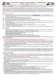
<strong>„A</strong> - <strong>series</strong> <strong>“</strong> <strong>Controllers</strong> <strong>for</strong> <strong>Brushless</strong> <strong>Motors</strong><br />
(Version 6.xx)<br />
<strong>„A</strong> – <strong>series</strong><strong>“</strong> controllers present a new basic line of controllers which are extremely easy to use - „as easy as it can be<strong>“</strong>. They take up on the<br />
sucessful and popular „Easy<strong>“</strong> controllers and feature many new possibilities and upgrades. <strong>Controllers</strong> are ready <strong>for</strong> immediate use without any<br />
settings – everything is automatic. <strong>Controllers</strong> belong to the TMM ® family.<br />
Even though these controllers are very easy to use, they are exceptionally quality controllers <strong>for</strong> "brushless" sensorless motors (BLCD motors). Should you need<br />
to change any parameters, it can be easily done using the transmitter or using the programming card UNICARD+. The set parameters are permanently saved in<br />
the controller´s memory.<br />
Thanks to the hi-tech TMM ® technology of <strong>MGM</strong> compro ® , also these A-<strong>series</strong> controllers have many outstanding features that significantly lower the possibilities<br />
of damage or destroy of not only the motor, but also battery packs as well as the controller itself. <strong>Controllers</strong> ensure maximal efficiency of the power unit with<br />
all sorts of motors. The BEC circuit is very powerful (except <strong>for</strong> A7, where the requirement <strong>for</strong> minimal dimensions and weight is a expressed).<br />
Basic features of <strong>„A</strong> – <strong>series</strong><strong>“</strong> :<br />
– Immediate operation without any settings or programming – as easy as it can be<br />
– Possibility to easily set important parameters (if you wish to) using transmitter or UNICARD+<br />
– Supports Lipol / Lion, A123 and NiCd / NiMH cells<br />
– Unmatched protection and management of batteries Lipol / Lion (here it is of a fundamental importance) as well as A123 cells and NiCd / NiMH<br />
– 3 adjustable levels of switch-off voltage<br />
– Adjustable strength of brake<br />
– Works perfectly with all types of motors – 2 up to 32 pole ones,<br />
outrunners (with rotating cover), and classic motors (rotor inside)<br />
– Perfectly masks interference and signal drop-outs<br />
– Extremely fine throttle step – 1023 values (steps)<br />
– Very soft starts<br />
– motor and controller overload protection<br />
– small dimensions and weight<br />
– Very powerful MEGA BEC (except <strong>for</strong> A7),<br />
or S-BEC <strong>for</strong> types <strong>for</strong> higher currents<br />
– protection against unwanted start<br />
– may be ordered also with a switch<br />
(safe connection, no accident due to malfunction of the switch)<br />
Important:<br />
It is recommended to measure current drawn from batteries (using<br />
clamp A-meter!) with a particular motor and propeller to ensure that a<br />
correct type of controller is used (dimensioning). It is necessary to<br />
measure with charged and „hardest<strong>“</strong> batteries (or at least with batteries<br />
with the highest capacity) which you wish to use in the set. This will prevent<br />
possible problems with overloading the controller, motor and batteries<br />
(especially Lipol cells are vulnerable to current overloading). Remember<br />
to ensure good cooling of the controller, especially when used<br />
near its limit parameters.<br />
One controller can control only one motor.<br />
1) Connecting the controller:<br />
� Opposite piece of the connector, which is on your batteries, should be soldered<br />
to the leading-in conductors to the battery. Use only quality golden<br />
plated kinds. Recommend are MP JET 1.8mm, 2.5 mm or 3.5 mm according<br />
to the type of controller and current. We recommend to put socket on<br />
the <strong>“</strong>-<strong>“</strong> wire (black wire) of the controller and the plug on the <strong>“</strong>+” wire (red<br />
wire).<br />
� The leads to the motor (yellow wires marked <strong>“</strong>A”, <strong>“</strong>B”, ”C”) should be sol-<br />
–<br />
battery<br />
+<br />
without switch<br />
with switch<br />
A<br />
B<br />
C<br />
to motor<br />
Programming also by-one-<strong>for</strong>-all <strong>MGM</strong> controllers card UNICARD+<br />
Controller connection to the RC equipment:<br />
dered directly to the motor or it is also possible to use the connectors mentioned above. If you decide to use connectors, this time solder sockets to the controller<br />
leads.<br />
� Insulate the connectors after soldering, e.g. using heat shrinking sleeve.<br />
� Receiver and antenna should be placed as far as possible from the controller, the batteries and power leads. Antenna<br />
should be placed as far as possible from lead strings, wires to rudder or carbon parts.<br />
� Connect the controller to throttle channel of your receiver.<br />
� If you need to feed the receiver or servos from some other source than BEC, carefully take out the central core of the<br />
servo cable connector (red wire) and insulate it properly.<br />
� Use power conductors as short as possible – it is the best <strong>for</strong> minimum weight as well as <strong>for</strong> lowering losses<br />
and possible interference. Do not make them shorter than 3 cm – possibility of unsoldering wires from the controller.<br />
� If motor runs in an opposite direction than desired, swap any two motor phases or change the revolution<br />
direction in the settings of the controller.<br />
� NOTICE, reversal of poles on wires to the batteries will reliably destroy the controller!<br />
(The damage however, may not show immediately, but in some later starts or flights !)<br />
� It is necessary to cool the controller in operation with flowing air. The closer to the limit parameters of<br />
the controller, the more intense cooling has to be ensured !<br />
� It is not allowed to feed the controller from any other source (such as mains power supply) than specified types of batteries !!!<br />
� Do not DISCONNECT the controller from batteries when motor RUNS or when it is still turning<br />
– that may lead to damage or destroy of the controller !!!<br />
servo<br />
servo<br />
servo<br />
SECURITY WARNING:<br />
Always disconnect the accumulators when not operating the model !!! Do not leave model with connected accumulators unattended !!! Please notice<br />
that running motor with propeller is very dangerous !!! If the controller is connected to batteries do not stay in the reach of the propeller ! Do<br />
not charge batteries when connected to the controller!<br />
� NOTICE, reversal of poles on wires to the batteries will reliably destroy the controller! (The damage however, may not show immediately, but in<br />
some later starts or flights!) Destroyed controller may then cause damage of feeding cells.<br />
� Short cut of these wires together (when batteries are connected) or short cut of these wires to the feeding voltage results in damage or destroy of<br />
the controller !<br />
� Make sure that the motor is in a good condition. A faulty or damaged motor (mechanical damages, shortcuts on winding, etc.) may cause<br />
damage or destroy of the controller as well as the feeding cells.<br />
receiver<br />
Main<br />
battery<br />
throttle channel<br />
other channels<br />
–<br />
A – <strong>series</strong><br />
+<br />
motor<br />
Notice:<br />
If you need to feed the receiver or<br />
servos from some other source than<br />
BEC, carefully take out the central<br />
core of the servo cable connector<br />
(red wire) and insulate it properly.
2) Starting:<br />
2 / 8 A-<strong>series</strong><br />
The controller is set automatically and meets the requirements of most users without any changes. The default settings also sets <strong>„A</strong>utomatic switching-off<br />
voltage<strong>“</strong> (due to wish of many modelers „not to set anything<strong>“</strong>), without distinguishing between the types of cells.<br />
In the <strong>„A</strong>utomatic switching-off voltage<strong>“</strong> mode, you do not need to take care of the type of the cell, as the switching-off voltage is set to 78% of the voltage of<br />
cells at switch on. This is safe if you switch the controller on always with fully charged batteries. The condition <strong>for</strong> fully charged cells applies primarily<br />
<strong>for</strong> Li-xxx and A123 cells. If you switch on controller with only partially charged cells, Lipol or A123 cells may get discharged too much. This is why it<br />
may be more suitable and safer to set the type of cells which you intend to use – see the programming chapter. However, the choice depends on your needs and<br />
requirements. Regarding Nixx cells, the situation is not so critical and it is possible to start even with a slightly discharged cells.<br />
The default controller settings:<br />
- Automatic switching-off voltage 78%<br />
- Brake (softer) on<br />
- Automatic Timing (sets optimal values <strong>for</strong> majority of factory manufactured motors) <strong>for</strong> 2 to 32 pole motors of classical conception (rotor inside) and<br />
also <strong>for</strong> so called outrunners (rotor is on the outer side).<br />
If this setting does not suit you <strong>for</strong> any reason, they can be easily changed – see the following parts 3, 4 and/or 5.<br />
a) Starting in mode<br />
"Automatic switching-off voltage":<br />
1. Turn the transmitter on<br />
2. Move throttle to minimum<br />
3. Turn the controller on.<br />
4. „melody<strong>“</strong> ��<br />
5. You may start<br />
The maximal throttle position<br />
is set automatically<br />
Notice: „melody<strong>“</strong> (case a) after the controller is switched on indicates that <strong>„A</strong>utomatic switching-off voltage<strong>“</strong> is set and there<strong>for</strong>e you should not start<br />
with discharged cells. If you set an exact type of cells (possibly also the number of cells, according to the type), „melody<strong>“</strong> changes to one short<br />
„beep<strong>“</strong> after switch on (case b).<br />
3) Meaning of the parameters:<br />
Parameter A – type of cells: Choice of type of batteries – it is possible to set Li-Pol, Li-ion (Li-xxx), A123 or NiCd, NiMH (Ni-xx) or <strong>„A</strong>utomatic switching-off<br />
voltage<strong>“</strong> mode. When Li-xxx or A123 cells are chosen, it is necessary to set number of cells in the following parameter. When you set a particular<br />
type of cells (that means Li-xxx, A123 or Ni-xx), „melody<strong>“</strong> changes to one short „beep<strong>“</strong> after switching the controller on – indication of the set mode.<br />
Parameter B – number of cells: Obligatory <strong>for</strong> Li-xxx and A123. For Ni-xx and <strong>„A</strong>utomatic switching off voltage<strong>“</strong> mode, this parameter may be skipped<br />
over (by inserting „Enter<strong>“</strong>) see below. Eventual setting of number of cells <strong>for</strong> Ni-xx and <strong>„A</strong>utomatic switch off voltage<strong>“</strong> is ineffective and the controller<br />
does not consider this setting.<br />
Parameter C – switching off voltage: This parameter affects the rate to which the cells are discharged when the revolutions start to be reduced as the batteries<br />
are low. Higher values of the switching-off voltage may be used not only <strong>for</strong> increasing the safety of discharging Li-xx cells (higher reserve<br />
against discharging the weakest cells too much) but also <strong>for</strong> gliders as this saves them more energy <strong>for</strong> servos <strong>for</strong> termic flying. For <strong>„A</strong>utomatic<br />
switching off voltage<strong>“</strong> mode, this parameter is ineffective and may be skipped over (by inserting „Enter<strong>“</strong>) see below. For details see Table 2.<br />
Parameter D – brake: Set the brake according to the model type and your use.<br />
Parameter E – timing: Here you may choose 5 different timings including automatic timing.<br />
It is strongly recommended to keep this setting (on automatic timing) because it ensures optimal settings and maximal efficiency. While<br />
using the definite values of timing, you may rise the motor revolutions or the twisting moment a bit but always at the expense of lowering the efficiency.<br />
If you wish to have higher revolutions it is better to use different motor or more cells because lower efficiency (due to higher timing) cannot<br />
be made up <strong>for</strong>. High value of timing may damage the controller in an unsuitable combination with some motors!<br />
For motors with high inductance in rate to maximal current or motors with weak magnets, <strong>for</strong> example some <strong>“</strong>LRK” or POT motors, lots of<br />
motors from CD ROMs, etc.), it is necessary to set the timing to 5° or more as the automatic timing may not be optimal. The need <strong>for</strong> setting other<br />
timing than the automatic one can be easily recognized – motor looses synchronization <strong>for</strong> higher loads.<br />
Parameter D – reverse: This parameter sets a reversed direction of motor rotation without the need of swapping two wires to the motor.<br />
Table 1 – Programming table <strong>for</strong> A – <strong>series</strong> controllers:<br />
parameter Parameter value � 0 (= ENTER) 1 2 3 4 5<br />
A Type of cells next parameter<br />
Automatic switching-off<br />
voltage<br />
Nixx Li-xxx A123 -<br />
B Number of cells next parameter 2 3 4 5<br />
C Switching-off voltage next parameter low medium high - -<br />
D Brake next parameter off on (softer) on (stronger) - -<br />
E Timing next parameter automatic 5° 10° 15° 20°<br />
F Reversal of motor revolutions end of program. no yes - - -<br />
Default settings is in underlined bold.<br />
Table 2 – switching-off voltage:<br />
Switchingoff<br />
voltage<br />
Choice<br />
�<br />
����<br />
��<br />
Automatic<br />
Ni-xx<br />
[V /cell]<br />
b) Start with set type of cells:<br />
(Nixx, A123 or Li-xxx)<br />
1. Turn the transmitter on<br />
2. Move throttle to minimum<br />
3.<br />
4.<br />
Turn the controller on.<br />
1x short „beep" ♪<br />
5. You may start. The maximal<br />
throttle position is<br />
set automatically<br />
A123<br />
[V /cell.]<br />
Li-xxx<br />
[V /cell]<br />
Important: If in the initial position of the throttle<br />
stick (min. throttle)<br />
3 „beeps" are heard ♪ ♪♪<br />
reverse<br />
the deflections of the throttle stick on the transmitter.<br />
If during the initial throttle stick position (max throttle =<br />
entering the programming) 1 beep ♪<br />
or „melody„<br />
can be hear ��<br />
���� �<br />
reverse the deflections of<br />
the throttle stick on the transmitter<br />
low 78% 0.7 2.3 2.9<br />
Suitable <strong>for</strong> operating two and more controller from one battery pack (models<br />
with multiple motors)<br />
medium 78% 0.9 2.6 3.2 Regular operation<br />
high 78% 1.0 2.8 3.5<br />
Suitable <strong>for</strong> gliders (more energy <strong>for</strong> servos and termic flying is saved)a it also<br />
lowers the possibility of undercharging the weakest cell.<br />
Notice: "Automatic switching-off voltage" mode.<br />
The advantage of automatic switching-off voltage is that you may easily change the type and number of cells without having to set the controller each time. The<br />
disadvantage is that it is necessary to start with fully charged cells - in this mode cells may get undercharged if you start with only partially charged cells. This<br />
mode is indicated by a "melody" after switching the controller on.<br />
note
4) Programming the controller using UNICARD+:<br />
All parameters may be easily set using the programming card UNICARD+.<br />
<strong>Controllers</strong> are programmed using servocable.<br />
One programming card can program all <strong>MGM</strong> compro controllers!<br />
Only tag is changed when different controllers are used.<br />
Connecting the controller to the programming card:<br />
3 / 8 A-<strong>series</strong><br />
brown<br />
• Insert the tag corresponding to your controller under the covering part of the card on both sides - top side "A<strong>“</strong> and bottom side "B<strong>“</strong>.<br />
• to connect the UNICARD+ with the controller, plug in the controller's servocable to the card communication connector.<br />
UNICARD+<br />
• Using the programming couplers connect pins on side <strong>„A</strong><strong>“</strong> (and on side „B<strong>“</strong> if necessary) corresponding to the parameters you wish to set. If incorrect combinations<br />
are set (e.g. 2 as well as 5 cell etc.), UNICARD+ warns of such error by switching on the red LED after it is connected to the controller.<br />
• Switch the controller on by connecting it to the battery (red and black wire – do not reverse poles!), and by switching on the switch <strong>for</strong> controllers equipped<br />
with it. Communication between the card and the controller will be carried out automatically and the required parameters will be transfered to the controller.<br />
Green LED blinks during the data transfer. The green LED stays lit up when the data transfer is finished correctly – now you may remove UNICARD+, programming<br />
is finished. Switch the controller off.<br />
• In case of incorrect connection, connection of different type of controller, setting of incorrect parameters etc. red LED lit up on the UNICARD+.<br />
For more detail instructions see the UNICARD+ instructions <strong>for</strong> use.<br />
5) Programming the controller using transmitter:<br />
If the default setting of the controller does not suit your needs from any reason, it is possible to change any of the programmable parameters. All programming<br />
(setting) is very simple and fast using transmitter and receiver. Nothing has to be disconnected and no connections have to be changed. After programming<br />
the set parameters are permanently saved into the controller’s memory (until next programming or setting the default settings).<br />
● Turn the transmitter on with the throttle stick in max position.<br />
● Turn the controller on. Controller shortly beeps 3x, after 10 seconds 3x long<br />
beeps will be heard. Now you have 3 seconds to move the throttle back to min.<br />
throttle.<br />
If in this time limit you do not put the throttle in min position the programming<br />
process will skip to the possibility of setting the default settings (see below),<br />
will end and the controller will be turned off. Its next operation is possible<br />
after switching off and then turning it on again.<br />
If you moved the throttle to the minimal position in the 3 seconds time limi, the<br />
motor will beep 1x long and you have entered the programming mode.<br />
Now you may start to program parameters according to the procedure described<br />
below, with no time limits.<br />
max. throttle<br />
● Setting requested „value<strong>“</strong> of parameters (basic procedure <strong>for</strong> setting in each parameter).<br />
Initial throttle stick position is in minimal throttle. Move the throttle stick to aproximatelly<br />
„½ throttle", motor beeps 2x. Move the throttle to min position, motor beeps 1x. Repeat<br />
the procedure (½ throttle - minimum) as many times as is the number of parameter<br />
which you wish to set (according to the table). For example to set value 3 in parame-<br />
min. throttle<br />
ter „E" (that is timing 10°) repeat the procedure (½ throttle - minimum) 3x (certainly,<br />
you have to be in this parameter already).<br />
● Programming of each parameter will be finished when you move the throttle<br />
from min position to the <strong>“</strong>full throttle” – motor will produce 3 long beeps. Move the throt- Enter :<br />
tle back to minimal position – you will hear 1 long beep (this sequence is called<br />
„ENTER<strong>“</strong>) – parameter is now set to the chosen value and saved. This automatically<br />
moves you to the next parameter, which value may be set according to the previous<br />
paragraph. The procedure will allow you to set all parameters one after another.<br />
min. throttle<br />
● After the last programmed parameter the controller must be switched off,<br />
which finishes the programming.<br />
������<br />
���� �<br />
½ throttle min. throttle<br />
Notes to programming:<br />
It is not onligatory to program all parameters, it is possible to switch the controller off after any parameter which is correctly finished by the „ENTER<strong>“</strong> sequence.<br />
The following parameters will not be changed and all the preceeding ones will be saved.<br />
If you do not wish to change some parameter (you wish to keep its last value), set "ENTER<strong>“</strong> directly when programming it (that is „full throttle<strong>“</strong>, after 3 beeps<br />
move the throttle to min, you will hear 1 beep). Thus no „ ½ throttle – min throttle<strong>“</strong> procedure. The last saved value will be kept <strong>for</strong> the parameter and the<br />
controller will get to the programming of the next parameter.<br />
EASY return to the default settings:<br />
min. throttle<br />
�<br />
Turn the controller on with full throttle as if you were going to<br />
program it. Controller will make 3 short beeps. After 10 sec- ♪ ♪ ♪ ��� ♪ ♪♪♪ onds 3 long beeps will be heard. Do not move the throttle<br />
back to min throttle, but wait <strong>for</strong> another 5 seconds <strong>for</strong> 4 max. throttle<br />
wait 10 sec. wait 5 sec. max. 3 sec. Default<br />
short beeps. If you now (after the 4 beeps) move the throttle<br />
Turn con-<br />
settings<br />
back to minimal position during 3 seconds time limit, the controller<br />
on<br />
troller beeps 1x and the default parameters are set. If the<br />
> 3 sec. Controller is<br />
throttle is not moved back, nothing is changed in the settings,<br />
turned off<br />
and the controller waits <strong>for</strong> switch off.<br />
Together with motor beeping, LED on the controller blinks.<br />
®<br />
Turn the<br />
controller<br />
on<br />
♪ ♪ ♪<br />
wait 10 sec. max. 3 sec.<br />
������<br />
�<br />
Min.throttle<br />
Development, manufacture, service:<br />
<strong>MGM</strong> compro, Ing. G. Dvorský Tel.: +420 577 001 350 E-mail: mgm@mgm-compro.cz<br />
Sv. Čecha 593, 760 01 Zlín Fax : +420 577 001 348 Info: www.mgm-compro.cz<br />
Programming<br />
mode<br />
�
Turn<br />
controller on<br />
Parameter A<br />
Parameter B<br />
. . . . .<br />
Parametr F<br />
3× beeps<br />
3× LED blinks<br />
Programming<br />
Max. 3 sec.<br />
time<br />
LED<br />
+<br />
BEEP<br />
4 / 8 A-<strong>series</strong><br />
Quick setting of default parameters<br />
transmitter time transmitter<br />
controller controller<br />
3× beeps<br />
3× LED blinks<br />
1× beep<br />
1× LED blink<br />
2× beeps<br />
2× LED blinks<br />
1× beep<br />
1× LED blinks<br />
3× beeps<br />
3× LED blinks<br />
1× beep<br />
1× LED blink<br />
2× beeps<br />
2× LED blinks<br />
1× beep<br />
1× LED blinks<br />
3× beep<br />
3× LED blinks<br />
1× beep<br />
1× LED blinks<br />
2×beeps<br />
2× LED blinks<br />
1× beep<br />
1× LED blink<br />
3× beeps<br />
3× LED blinks<br />
1× beep<br />
1× LED blink<br />
♪ ♪ ♪<br />
wait 10 seconds<br />
�� ����<br />
��<br />
Turn the controller off<br />
Throttle to „max.<strong>“</strong> position.<br />
Turn transmitter on<br />
Throttle down to „min.<strong>“</strong><br />
in 3 seconds time limit!<br />
You are in the PROGRAMING MODE<br />
Now there are no more time limits<br />
���� Setting the value of<br />
parameter A<br />
„type of cells<strong>“</strong><br />
��<br />
�� ����<br />
��<br />
1× <strong>for</strong> value 1,<br />
2× value 2, etc.<br />
ENTER that is saving<br />
and moving to the next<br />
parameter (B)<br />
���� Setting the value of<br />
parameter B<br />
„number of cells<strong>“</strong><br />
��<br />
�� ����<br />
��<br />
1× <strong>for</strong> value 1,<br />
2× <strong>for</strong> value 2, etc.<br />
ENTER that is saving<br />
and moving to<br />
the next parameter(C)<br />
etc. <strong>for</strong> the next<br />
parameters<br />
���� Setting the value of parameter<br />
F: „reversal of<br />
motor revolutions<strong>“</strong><br />
��<br />
�� ����<br />
��<br />
1× <strong>for</strong> value 1,<br />
2× <strong>for</strong> value 2, etc.<br />
ENTER that is saving and<br />
end of programming<br />
(all values are saved)<br />
Turn<br />
controller on<br />
3× beeps<br />
3× LED blinks<br />
3× beeps<br />
3× LED blinks<br />
4× beeps<br />
4× LED blinks<br />
1× beep<br />
1× LED blinks<br />
LED<br />
+<br />
BEEP<br />
Here you may turn the<br />
controller off anytime<br />
after inserting ENTER, if<br />
you do not wish to<br />
change the following<br />
parameter.<br />
All parameters confirmed<br />
by ENTER were saved.<br />
Legend:<br />
♪ ♪ ♪<br />
�� ����<br />
wait 5 seconds<br />
♪�♪�<br />
♪�♪�<br />
♪�<br />
Turning the controller on<br />
by switch or connecting<br />
it to the accumulators<br />
♪<br />
����<br />
wait 10 seconds<br />
Throttle down to „min.<strong>“</strong><br />
in 3 seconds ! *)<br />
DEFAULT SETTINGS<br />
is restored<br />
Turn the controller off<br />
Throttle to „max.<strong>“</strong> position.<br />
Turn transmitter on<br />
Throttle stays in<br />
„max.<strong>“</strong><br />
*) if you do not throttle down in the 3 seconds<br />
time limit, the controller turns itself<br />
off without any change in settings<br />
��<br />
short „beep<strong>“</strong> long „beep<strong>“</strong><br />
„melody<strong>“</strong><br />
Turning the controller off<br />
by switch or disconnecting<br />
it from the accumulators<br />
min. throttle ½ throttle max. throttle<br />
Move to aprox. ½ throttle,<br />
after 2 beeps back to min. throttle<br />
Move to full throttle,<br />
after 3 beeps back to min. throttle<br />
(= ENTER)
5 / 8 A-<strong>series</strong><br />
Programming example: You wish to set 3 Lipol cells and a stronger brake.<br />
1) Turn the transmitter on with the throttle stick in max position.<br />
2) Turn the controller on. Controller shortly beeps 3x, after 10 seconds 3x long beeps will be heard. Move the throttle back to min throttle, you will hear 1 long beep - you are<br />
in the programming mode and will be programming the first parameter "A", type of cells (see the table). You wish to set „Lipols<strong>“</strong>, thus value „3<strong>“</strong> in parameter <strong>„A</strong><strong>“</strong>.<br />
3) Move the throttle stick to „1/2 throttle", motor beeps 2x (long beeps). Move the throttle to min position, motor beeps 1x (long beep) (this sets A = 1). Repeat this procedure<br />
two more times (sets A = 3, that is Li-xxx cells).<br />
4) This setting must be confirmed by „ENTER<strong>“</strong>. Move the throttle stick to full throttle, motor beeps 3x (long beeps). Move the throttle back to min position, motor beeps 1x<br />
(long beep) = ENTER, now you have set Li-xxx cells. Together with that the programming has moved onto the next parameter „B<strong>“</strong> – number of cells.<br />
5) Move the throttle stick to „1/2 throttle", motor beeps 2x. Move the throttle back to min position, motor beeps 1x (this sets B = 1). Repeat this 1x, parameter „B<strong>“</strong> will be set<br />
to value 2 (B=2, that is number of cells = 3).<br />
6) This setting must again be confirmed by „ENTER<strong>“</strong>. Move the throttle stick to full throttle, motor beeps 3x. Move the throttle back to min position, motor beeps 1x =<br />
ENTER, now you have set number of cells = 3.<br />
7) Because you do not wish to change the next parameter (switching-off voltage), follow directly with „ENTER<strong>“</strong> (move the throttle stick to full throttle, motor beeps 3 times,<br />
Move the throttle to min position, motor beeps 1x), by doing this you have skipped over parameter „C<strong>“</strong>. Now you will be setting parameter „D<strong>“</strong>, brake. You will be setting<br />
value 3, stronger brake.<br />
8) Move the throttle stick to „1/2 throttle", motor beeps 2x (long beeps). Move the throttle back to min position, motor beeps 1x (long beep) (this sets D = 1). Repeat this<br />
procedure two more times (sets D = 3, that is stronger brake).<br />
9) This setting must again be confirmed by „ENTER<strong>“</strong>. Move the throttle stick to full throttle, motor beeps 3x. Move the throttle back to min position, motor beeps 1x =<br />
ENTER, now you have set stronger brake.<br />
10) As you do not wish to change the following parameters, turn the controller off, all the required changes are set.<br />
11) When the controller is turned on again, it starts with the newly set parameters (they are permanently saved until further changes).<br />
Protective and safety mechanisms of TMM ® controllers:<br />
<strong>Controllers</strong> mask interference and signal losses <strong>for</strong> as long as 1.5 seconds. Motor revolutions are gradually reduced <strong>for</strong> longer lasting signal drop outs or interference.<br />
When the signal is restored, the controller goes smoothly back to the required power. Long lasting signal drop out (or its absence) is indicated acoustically by motor as<br />
well as by LED. This comes in handy when e.g. looking <strong>for</strong> a lost model.<br />
Motor does not start, if the controller does not receive a correct signal from the receiver (e.g. when the transmitter is turned off). It also does not start until the throttle<br />
stick is not in „motor turned off<strong>“</strong> position after switch on – that is in the neutral position <strong>for</strong> "grip pistols<strong>“</strong> transmitter type or „minimal throttle<strong>“</strong> <strong>for</strong> regular transmitters (without<br />
neutral).<br />
Temperature fuse of the controller is set to 90°C, when the power is reduced to ca 60%. After cooling off (even during the flight), the controller goes back to the required<br />
power. Temperature is checked also after switch on and if it is above 70°C, the controller does not start. New start is possible after the controller is cooled off below<br />
this value.<br />
Current fuses of the controller turn the controller off or limit the currents during current overload of the controller. New start is possible after the throttle is moved back<br />
to neutral (minimal position <strong>for</strong> transmitters without neutral).<br />
Circuits monitoring voltage take care of the correct moment <strong>for</strong> disconnecting the motor when the batteries get discharged – not only that the batteries do not get undercharged<br />
but also enough energy is retained <strong>for</strong> servos after the motor is turned off ( when the battery is discharged).<br />
Advantages of these mechanisms <strong>for</strong> TMM ® controllers:<br />
1) Thanks to the use of the automatic current fuse (ACF) the possibility of current overload of controller, motor and batteries (and their possible damage) even at crisis<br />
points is significantly reduced - controller disconnects the motor.<br />
2) the used system of intelligent power reduce (IPR) always ensures through measurements of voltage, currents, battery condition and calculations an optimal point of<br />
starting continuous reduction of motor per<strong>for</strong>mance (or the point when motor is switched off, according to the setting), so that the battery cells do not get extremely discharged<br />
– which is very important specially <strong>for</strong> Lipol cells. This, not mentioning other advantages, reduces the possibility of reversal of poles of lower cells (applies<br />
mainly to NiCd / NiMH cells).<br />
3) This system at the same time enables retaining defined energy <strong>for</strong> BEC (perfect RPC) – applies to controllers with BEC. It is extremely important <strong>for</strong> flying models<br />
(you do not crash due to not having enough energy <strong>for</strong> receiver and servos). The amount of retained energy can be set by the user.<br />
4) the automatic current reduce (ACR) does not allow a drop in voltage <strong>for</strong> BEC even under extremely big current load.<br />
When switching the motor off (reducing power) at a solid boundary as it is with standard controllers (chart a) it is not possible to determine the amount of energy <strong>for</strong> BEC<br />
which is kept in the controller after the motor is switched off. It strongly depends on currents and inner resistance of the battery. The better the cells (harder) you have and<br />
the smaller the instantaneous current, the less energy (= time) remains <strong>for</strong> landing after the motor is switched off by the controller. On the other hand, the worse the cells and<br />
the higher the instantaneous currents, the more energy remains – but you do not know how much energy exactly.<br />
Comparing to this, TMM controllers (chart b) ensures that the remaining energy (after the motor is switched off by the controller) is practically independent on currents and<br />
inner resistance of the battery and it is possible to change its amount <strong>for</strong> some types of controllers according to one's needs (higher <strong>for</strong> gliders, etc.). From the motor operation<br />
time view it is usually an insignificant amount of energy, the motor power would decrease very fast anyway. However, this energy is very significant in regards to feeding<br />
BEC.<br />
U<br />
4.2V<br />
čl.<br />
a) standard controllers<br />
(12.6V)<br />
Voltage of the battery <strong>for</strong> current:<br />
0.5C 5C<br />
10C 20C<br />
Residual energy <strong>for</strong> BEC is<br />
strongly dependent on the<br />
actual current<br />
Switching-off voltage:<br />
3.6V / cell (10.8V)<br />
3.3V / cell (9.9V)<br />
3.0V / cell (9.0V)<br />
2.7V / cell (8.1V)<br />
60% 80% 100% Capacity<br />
95% [mAh]<br />
Regular controllers (even Lipol compatible) have either a solid switching off<br />
voltage (<strong>for</strong> example 3V per cell) or it is possible to set this value. For example<br />
<strong>for</strong> set boundary 3V per cell the controller is switch off or it starts to reduce revolutions<br />
when this value is reached no matter how big the drawn current is. This<br />
means that the residual energy significantly changes according to a instantaneous<br />
current load of batteries (and also according to inner resistance<br />
of the cells] from 0 to 95 % - depending only on the set voltage boundary. If the<br />
example on the graph above is considered with a set boundary of 3V per cell<br />
the controller will switch off when drawn current is 20C when there is still 40% of<br />
energy still left, while <strong>for</strong> 5C current when only 5% of energy is left. For boundary<br />
of 3.3V per cell the controller would switch off <strong>for</strong> currents of 20C when only<br />
few percent of energy were consumed while <strong>for</strong> 5C after 92% of energy would<br />
be consumed.<br />
U<br />
4.2V<br />
čl.<br />
b) TMM ® controllers of <strong>MGM</strong> compro<br />
(12.6V)<br />
Voltage of the battery <strong>for</strong> current: Switching-off voltage:<br />
0.5C 5C 10C 20C<br />
Defined residual<br />
energy <strong>for</strong> BEC<br />
3.8V / cell.<br />
75% 90% 100%<br />
95%<br />
3.7V / cell<br />
(boundary <strong>for</strong> starting<br />
motor revolutions<br />
reduction)<br />
3.6V / cell (10.8V)<br />
3.3V / cell (9.9V)<br />
3.0V / cell (9.0V)<br />
Capacity<br />
[mAh]<br />
TMM ® controllers handle the situation quite differently. The switching off voltage is<br />
always recalculated into „inner<strong>“</strong> voltage of the battery – there<strong>for</strong>e is independent on<br />
both drawn current as well as inner resistance of the accumulator. This means the<br />
set residual energy is always the same and does not depend on currents and<br />
inner resistance of battery. Batteries are then always discharged to same level,<br />
regardless how big currents are drawn. The value of set residual energy is there<strong>for</strong>e<br />
only little dependent on the features of battery and the discharging current. For example<br />
<strong>for</strong> switching voltage 3.7V per cell controller switches off the motor or starts to<br />
reduce revolutions always after 90% of energy is used up no matter if the drawn current<br />
is 20C or 5C.<br />
(The voltage of accumulator after switch of the current always rises to a value close<br />
to curve of 0.5V – this discharging curve is close to „inner<strong>“</strong> voltage of battery. This<br />
curve describes how much the controller is discharged.
Technical data:<br />
6 / 8 A-<strong>series</strong><br />
Temperature of the environment: 0°C up to 40°C number of regulation steps: 1024 / full throttle<br />
Motor control: PWM 8 kHz Max. rpm <strong>for</strong> 2 pole motor: ~170 000 rpm<br />
Control signal: Positive pulses 1.5 ± 0,8 ms, period 10 up to 30 ms or HRS<br />
BEC (A7): 5V / max. 3.2 A (<strong>for</strong> BEC load, see graph on page 7)<br />
MEGA BEC (A12 up to A40): 5V / max. 4,0 A (<strong>for</strong> BEC load, see graph on page 7)<br />
S-BEC (A56 up to A112): 5V / max. 6.0 A (<strong>for</strong> BEC load, see graph on page 7)<br />
Power supply: Only from batteries: Li-Pol, Li-Ion, A123, NiCd, NiMH (use of another power supply is restricted!)<br />
Suitable <strong>for</strong> motors: Mega AC, Model <strong>Motors</strong>, MP JET, PJS, Überall model, Hacker, HCS, Kontronik, LRK, Plettenberg etc.<br />
They are not suitable <strong>for</strong> special motors requiring controlling frequency PWM higher than 8kHz (Tango from Kontronik,<br />
etc.).<br />
A – <strong>series</strong> A 7 A 12 A 18 A 25 A 40 A 56 A 74 A112<br />
Dimensions [mm]: 22×18×4.5 25×23×6 28×25×6 28×25×6 36×28×6 50×31×10 50×31×16 50×31×16<br />
Dimensions (incl. external capacitor) [mm]: 22×18×4.5 25×23×6 36×25×6 36×25×6 48×28×6 62×31×10 62×31×16 62×31×16<br />
Weight inc. all power conductors:<br />
Weight without power conductors:<br />
6.8 g<br />
4.5 g<br />
9.4 g<br />
7.1 g<br />
16.5 g<br />
10.2 g<br />
19 g<br />
10.2 g<br />
31 g<br />
17 g<br />
44 g<br />
44 g<br />
58 g<br />
30 g<br />
61 g<br />
44 g<br />
No. of feeding Li-Ion / Li-Pol cells: 2 – 3 2 – 3 2 – 4 2 – 4 2 – 4 2 – 4 2 – 4 2 – 4<br />
No. of feeding A123 cells: -- 2 – 3 2 – 4 2 – 4 2 – 4 2 – 5 2 – 5 2 – 5<br />
No. of feeding NiCd / NiMH cells: 6 – 9<br />
Maximal feeding voltage: 12.6V<br />
Max. continuous current / peak (5 sec. / 25°C): 7A / 10A<br />
On-state switch resistance at 25°C, typical: 2×18 mΩ<br />
BEC voltage: 5V<br />
Max. BEC current: 1,5A<br />
6 – 9<br />
12.6V<br />
12A / 15A<br />
2×6.3 mΩ<br />
5V<br />
1.5A<br />
6 – 12<br />
16.8V<br />
18A / 23A<br />
2×3.7 mΩ<br />
5V<br />
4A<br />
6 – 12<br />
16.8V<br />
25A / 30A<br />
2×3.1 mΩ<br />
5V<br />
4A<br />
6 – 12<br />
16.8V<br />
40A / 50A<br />
2×1.8 mΩ<br />
5V<br />
4A<br />
6 – 12<br />
18V<br />
12A / 70A<br />
2×1.2 mΩ<br />
5V<br />
6A<br />
6 – 12<br />
18V<br />
12A / 90A<br />
2×0.9 mΩ<br />
5V<br />
6A<br />
6 – 12<br />
18V<br />
12A / 140A<br />
2×0.6 mΩ<br />
5V<br />
6A<br />
No. of standard servos <strong>for</strong> 2 Lipol / 3 Lipol / 4 Lipol: 3 / 2 / – 5 / 4 / – 6 / 5 / 4 10 / 10 / 10 *)<br />
*) depends certainly on the type of the serov and its load<br />
� Temperature fuse lowers the motor power to half when the temperature of the controller exceeds ~100°C.<br />
� Current fuse switches the motor off when the allowed limits are exceeded. It is possible to start the motor back after throttling down to minimum.<br />
� When voltage of batteries is almost empty, the controller starts to continuously reduce the motor revolutions.<br />
� If the voltage of Lipol cells is lower than ~3.4V/cell (without load) at the moment of connection to the controller, the controller will not start the motor because the cells are<br />
almost discharged and it there<strong>for</strong>e makes no sense to start (during the take-off, the little energy there left could be soon exhausted, the motor power would be reduced and<br />
the model may crash).<br />
The appearance and the technical data may be changed without prior notice.<br />
Error messages (the controller must be switched off to correct the error, then switched on again):<br />
� low size of deflection of control pulses – you must increase the size of deflection of the throttle stick on the transmitter<br />
� Exceeding the border limits of control pulses (0.7ms and 2.3 ms) – you must shorten the size<br />
of deflection of the throttle stick on the transmitter<br />
� Starting with an overheated controller<br />
� More or less cells than specified<br />
LED<br />
� �<br />
0,25 0,25<br />
� current overload (resumes operation after dropping throttle to min. throttle, it is not necessary to switch the controller off in this case)<br />
♪<br />
� Long lasting signal drop out ………………………………………………………………. LED 0,1 2,0<br />
WARNING: You risk damaging or destroying the controller <strong>for</strong>:<br />
� connecting more battery cells to the controller than the max. number specified in the technical data<br />
� reversing power connections to the battery<br />
� shortcutting of wires to the motor when batteries are connected or changing motor and battery outlets<br />
� overloading of the BEC with bigger currents or bigger power loss than is specified in the technical data<br />
� dipping the controller in water, or water penetrating to the controller, metal (conductive) objects in the controller<br />
� disconnecting the controller from batteries or turning off the controller while motor is running (or still turning)<br />
� Feeding them from power supply other than the specified batteries<br />
Used abbreviations and terms<br />
ACF - automatic current fuse<br />
ACR - automatic current reduction<br />
APS - automatic parameter setup<br />
BEC - battery eliminator circuitry – circuit ensuring feeding of servos nas receiver from the main battery - replaces receiver batteries<br />
BLCD - brushless DC motor – brushless direct current electromotor<br />
IPR - intelligent power reduction – system of intelligent power reduction when batteries are low<br />
LED - light emitting diode<br />
PWM - pulse width modulation – used <strong>for</strong> loss less control of motor power<br />
RPC - radio priority circuit – priority preservation of sufficient voltage <strong>for</strong> BEC<br />
� � �<br />
♪� ♪<br />
Numbers give aprox. length is seconds
BEC A- <strong>series</strong> A7: <strong>Controllers</strong> are equipped with BEC which is<br />
able to supply peak currents of up to 3,2A. Power loss load capability<br />
is proportional to dimensions. It may not exceed ~8W. It is possible<br />
to determine from the graph, e.g. current, which may be<br />
drawn from BEC under given load and voltage and also find out <strong>for</strong><br />
how long. The power losses of the BEC warm the controller up. If<br />
the BEC is loaded with the power loss >2.5W pauses <strong>for</strong> cooling<br />
are necessary so that the average power loss is < 2.5W.<br />
REMEMBER that the controller is also heated by the power<br />
loss generated in the motor part!<br />
Power loss of 5V BEC: (UBATT – 5V) × current I<br />
(it is favorable to use axis with difference of voltages UBATT – UBEC)<br />
Example: (see graph) if the voltage of batteries is 8.4V, it is possible<br />
to draw current of 1.1A continuously <strong>for</strong> up to 10 seconds from<br />
the BEC with power loss of 4W. If the load would last only 2.5 seconds,<br />
the power loss may be up to 6W and it is possible to draw<br />
current up to 1.7A.<br />
It is not protected against shortcut!<br />
MEGA BEC (A-<strong>series</strong> A18 – A40): <strong>Controllers</strong> are<br />
equipped with BEC which is able to supply peak currents of up to<br />
4A. Power loss load capability is extremely high, but it also has its<br />
limits. It may not exceed ~20W. It is possible to determine from the<br />
graph, e.g. current, which may be drawn from BEC under given<br />
load and voltage and also find out <strong>for</strong> how long. The power losses<br />
of the BEC warm the controller up. It is necessary to remove the<br />
generated heat by airflow. If the BEC is loaded with the power<br />
loss > 5W pauses <strong>for</strong> cooling are necessary so that the average<br />
power loss is < 5W. REMEMBER that the controller is also<br />
heated by the power loss generated in the motor part!<br />
Power loss of 5V BEC: (UBATT – 5V) × current I<br />
(it is favorable to use axis with difference of voltages UBATT – UBEC)<br />
Example: (see graph) if the voltage of batteries is 10.5V, it is possible<br />
to draw current of 1.8A continuously <strong>for</strong> up to 10 seconds from<br />
the BEC with power loss of 10W. If the load would last only 5 seconds,<br />
the power loss may be up to 15W and it is possible to draw<br />
current up to 2.7A.<br />
Only <strong>“</strong>MEGA BEC” version features protection against long<br />
lasting shortcut !<br />
S BEC (switched BEC, A56 – A112): TMM controller <strong>for</strong><br />
higher powers use switched BEC (see table woth parameters on<br />
page 6). The switched BEC is favorable in operation with higher input<br />
voltage as the losses are lower or to put it differently, it enables<br />
to draw significantly higher currents even from higher input voltage.<br />
Load characteristics differ significantly from those of linear BECs.<br />
However, also this type of BEC has its limits even though it is much<br />
less dependent on input voltage than linear type of BEC.<br />
Current load normally decreases with rising temperature. Maximal<br />
time <strong>for</strong> which a given current may be drawn is shown in the graph<br />
and it also decreases with rising temperature. Also this type of BEC<br />
must be cooled by airflow when drawing higher currents.<br />
S BEC may endure a short time short-circuit on output without<br />
damage.<br />
It is possible to also use strong digital servos.<br />
Example: 4 Lipol cells battery (that is 16.8V charged, ~16V under<br />
load). Your servos draw 3A. S BEC endures this current <strong>for</strong> 120<br />
sec. (red curve) without pauses <strong>for</strong> cooling. In real operation such<br />
situation is rare; the situation is usually more favorable as the servos<br />
are not working continuously and do not have a continuous<br />
draw all the time – in such intervals without load or with a small<br />
load BEC is cooled.<br />
When exceeding the maximal limits of current or power<br />
losses, BEC may be destroyed and the model may become<br />
uncontrollable !<br />
Please, notice that servos loaded with the control surfaces (rudder,<br />
ailerons etc.) in the air draw many times more current than when<br />
you move them on the ground !<br />
Max. current „I<strong>“</strong> drawn from BEC [A]<br />
Max. current „I<strong>“</strong> drawn from BEC [A]<br />
7 / 8 A-<strong>series</strong><br />
3.2<br />
2.4<br />
1.6<br />
0.8<br />
difference<br />
UBATT -UBEC<br />
4A<br />
3A<br />
2A<br />
1A<br />
0<br />
2.7 A<br />
1.8 A<br />
difference 1<br />
UBATT -UBEC [V]<br />
Max. current „I<strong>“</strong> drawn from „S BEC<strong>“</strong> [A]<br />
7A<br />
6A<br />
5A<br />
4A<br />
3A<br />
2A<br />
1A<br />
0<br />
8.4 V<br />
2,5 W<br />
continuous<br />
5 6 7 8 9 10 11 12 13 14<br />
UBATT [V]<br />
Load Capability of MEGA BEC<br />
10.5V<br />
RESTRICTED AREA<br />
5 6 7 8 9 10 11 12 13 14 15 16 17<br />
2<br />
3<br />
4<br />
5 6 7 8 9 10 11 12<br />
Power loss<br />
of BEC:<br />
8 W /0.5 sec<br />
6 W / 2.5 sec.<br />
4 W / 10 sec.<br />
Power loss<br />
of BEC:<br />
20 W / 1 sec.<br />
15 W / 5 sec.<br />
10 W / 10 sec.<br />
5 W / continuous<br />
Notice: be careful when determining the range of the set, especially when using more batteries – in case of signal loss servos might turn to their maximum<br />
which would cause significant rise in drawn current This might lead to a power overload of BEC with all its consequences. The danger is lower <strong>for</strong> receivers<br />
which set a defined servo position when loss of signal occurs.<br />
Connecting BEC: if two controllers are used in a model, BEC can be connected in two ways:<br />
a) if each controller is switched on separately (by switch or by connection to batteries ) it is possible to use only one BEC – it is necessary to take out the<br />
middle core of servoconnector of one of the controllers<br />
b) if a simultaneous switch on of both controllers is ensured (connected „+<strong>“</strong> and „–<strong>“</strong> wires of both controllers, without switches) both BECs can stay connected.<br />
This will also increase allowed current and power loads (aprox. twice) of BECs connected in this way. This will also increase allowed current<br />
and power loads (aprox. twice) of BECs connected in this way.<br />
6<br />
1.7 A<br />
1.1 A<br />
1<br />
2<br />
3<br />
Load capability of BEC<br />
4<br />
RESTRICTED AREA<br />
5 6 7 8 9<br />
Load Capability of „S BEC<strong>“</strong> <strong>for</strong> A-<strong>series</strong><br />
8 10 12 14 16 18 20 22 24 26<br />
UBATT [V]<br />
max. 18V<br />
RESTRICTED AREA<br />
UBATT [V]<br />
5 sec.<br />
10 sec.<br />
15 sec.<br />
25 sec.<br />
45 sec.<br />
120 sec.<br />
continuously
���<br />
��<br />
��<br />
QUICK START „ A – <strong>series</strong> <strong>“</strong> :<br />
The controller is defaults set and ready <strong>for</strong> immediate use, in the „automatic switching-off voltage<strong>“</strong> mode.<br />
Solder suitable connectors to the controller wires to batteries (red wire „plus<strong>“</strong>, black wire „minus<strong>“</strong>). Yellow leads to the motor should be either soldered directly to<br />
the motor or it is possible to use suitable connectors. The shorter the wires between the battery and the controller the better. Be careful to use only suitable connectors<br />
- MP JET 1.8 - 3.5 are recommended.<br />
Connect the servocable to the throttle channel of your receiver.<br />
Default settings: - „automatic switching-off voltage<strong>“</strong> (78% of voltage when the controller is turned on)<br />
- „soft brake<strong>“</strong> turned on<br />
- automatic timing<br />
- reversal of motor revolutions – „no<strong>“</strong><br />
Starting:<br />
1) Switch the transmitter on in the „minimal throttle" position (motor turned off).<br />
2) Switch the controller on by connecting it to the fully charged battery pack (or charged to at least 90% and more), <strong>for</strong> types with switch also with the switch ( =<br />
disconnecting the contacts of the switch). DO NOT REVERSE POLES!<br />
3) Controller will play a „melody<strong>“</strong> . If you have set a particular type of cells and the switching off voltage, short beep will be heard instead of the<br />
"melody<strong>“</strong>.<br />
♪ ♪♪<br />
If instead of the described sounds 3 short beeps are heard , you have either:<br />
- reversed deflections of throttle channel on the transmitter – it is necessary to reverse the deflections on the throttle channel of the transmitter or<br />
- the minimum of throttle is moved extremely "up" towards full throttle (e.g. by trim) - the best is to reset the transmitter settings<br />
4) Move the throttle up to full throttle triggers the motor and you may start.<br />
The controller automatically determines full deflection of throttle and spreads the control over the whole track of throttle.<br />
If the motor is turning in an opposite direction than you need, swap any two yellow wires to the motor (to do this turn the controller off at first and disconnect the<br />
batteries) or change the settings in the controller (using the programming card or the transmitter) according to what is easier <strong>for</strong> you.<br />
If you wish to enjoy all the possibilities of the controller, please refer to the whole manual.<br />
a) Starting in mode<br />
"Automatic switching-off voltage":<br />
1. Turn the transmitter on<br />
2. Move throttle to minimum<br />
3. Turn the controller on.<br />
4. „melody<strong>“</strong> ��<br />
5. You may start<br />
The maximal throttle position<br />
is set automatically<br />
����<br />
��<br />
b) Start with set type of cells:<br />
(Nixx, A123 or Li-xxx)<br />
1. Turn the transmitter on<br />
2. Move throttle to minimum<br />
3.<br />
4.<br />
Turn the controller on.<br />
1x short „beep" ♪<br />
5. You may start. The maximal<br />
throttle position is<br />
set automatically<br />
Notice: „melody<strong>“</strong> (case a) after the controller is switched on, indicates that the <strong>„A</strong>utomatic switching-off voltage<strong>“</strong> is set and there<strong>for</strong>e you should not<br />
start with partially discharged cells. If you set an exact type of cells (possibly also the number of cells, according to the type), „melody<strong>“</strong> changes<br />
to one short „beep<strong>“</strong> after switch on (case b).<br />
SECURITY WARNING:<br />
Always disconnect the accumulators when not operating the model !!! Do not leave model with connected accumulators unattended !!!<br />
Please notice that running motor with propeller is very dangerous !!! If the controller is connected to batteries do not stay in the reach of<br />
the propeller ! Do not charge batteries when connected to the controller!<br />
� NOTICE, reversal of poles on wires to the batteries will reliably destroy the controller! (The damage however, may not show immediately, but in<br />
some later starts or flights!)<br />
� Short cut of these wires together (when batteries are connected) or short cut of these wires to the feeding voltage results in damage or destroy of<br />
the controller !<br />
� Make sure that the motor is in a good condition. A faulty or damaged motor (mechanical damages, shortcuts on winding, etc.) may cause<br />
damage or destroy of the controller as well as the feeding cells.<br />
®<br />
♪<br />
Important: If in the initial position of the throttle<br />
stick (min. throttle)<br />
3 „beeps" are heard ♪ ♪♪<br />
reverse<br />
the deflections of the throttle stick on the transmitter.<br />
If during the initial throttle stick position (max throttle =<br />
entering the programming) 1 beep ♪<br />
or „melody„<br />
can be hear �� ���� �<br />
reverse the deflections of<br />
the throttle stick on the transmitter<br />
Development, manufacture, service:<br />
<strong>MGM</strong> compro, Ing. G. Dvorský Tel.: +420 577 001 350 E-mail: mgm@mgm-compro.cz<br />
Sv. Čecha 593, 760 01 Zlín Fax : +420 577 001 348 Info: www.mgm-compro.cz