Manual - MGM COMPRO Top
Manual - MGM COMPRO Top
Manual - MGM COMPRO Top
- TAGS
- manual
- compro
- mgm-compro.com

Create successful ePaper yourself
Turn your PDF publications into a flip-book with our unique Google optimized e-Paper software.
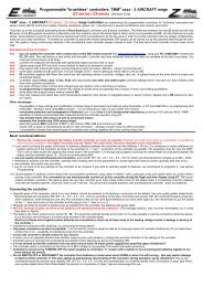
Programmable controllers TMM ® xxxx – 3 HELI for brushless sensorless motors (Version 2.52 and higher)<br />
TMM ® xxxx - 3 HELI controllers have been developed for helicopters and may be operated in one mode without constant revolutions and in one<br />
mode featuring constant revolutions (governor mode). They are manufactured with the use of surface mounting from high-end components and are controlled by a<br />
very powerful processor. Programming parameters are then saved permanently. The revolution regulation is extremely fine - 1024 steps all the way to the full throttle. The<br />
Mega BEC circuit (applies to versions with BEC) is also extremely powerful.<br />
Thanks to the high-tech TMM ® technology of <strong>MGM</strong> compro controllers feature number of outstanding properties which considerably eliminate the possibility of unwanted<br />
damage or destroy of motor, the batteries and the controller itself. Controllers also ensure the maximal efficiency with different kinds of motors.<br />
Maximum attention is paid to development which is in continuous progress. To make our newest knowledge available to our customers the upgrade of SW is free (only<br />
shipping costs are charged).<br />
The quality of products is under constant supervision in manufacture. Every controller goes through numerous tests. The final test of each controller is done under the<br />
controller’s full load.<br />
Protective and safety mechanisms of TMM ® controllers:<br />
Accumulators are protected in three ways. Firstly, due to the use of automatic current fuse (ACF) the current overload of accumulators (and their possible damage)<br />
even at crisis points can be avoided. Secondly, the used system of intelligent power reduce (IPR) always ensures through measurements of number of cells, voltage, currents,<br />
accumulator condition and calculations an optimal point of starting continuous reduction of motor performance (it is applied when accumulators become heavily discharged)<br />
so that accumulator cells do not get extremely discharged. This, not mentioning other advantages, reduces the possibility of reversal of poles of lower cells.<br />
This system at the same time enables retaining defined energy for BEC (perfect RPC) in controllers that have BEC which is of great significance for flying models (a<br />
crash due to running out of energy for receiver and servos can be avoided) Thirdly, it is the automatic current reduce (ACR) due to which a drop in voltage for BEC under extremely<br />
big current load (for every given controller) while motor starts does not occur. System also enables to indicate with programmed „time advance“, that batteries<br />
will be discharged soon This is very important for helicopters because at the begging of revolution reductions (almost discharged battery) there<br />
is usually not enough energy for flight.<br />
The controllers efficiently mask interference and drop-outs up to 1,5 sec. When long-lasting drop-outs or interference occur the controller slowly reduces motor revolutions.<br />
After the signal is resumed the controller continuously gets to the requested power. Without the proper signal from the transmitter (e.g. transmitter is turned off), the<br />
motor neither jerks nor runs but is at standstill.<br />
Thermal fuse of the controller is set at 90°C – the controller only indicates this situation, it does not reduce power! After switching on, the temperature above 70°C is<br />
monitored; if the temperature is higher the controller does not start. New start is possible only after the controller temperature falls. Take notice that the controller warms up<br />
not only due to losses on switching transistor but also due to loss on BEC.<br />
Intelligent power reduce (IPR) and retaining enough energy for BEC (RPC):<br />
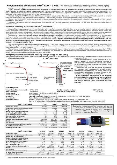
The controller’s behavior at the point of exhausted batteries (or closely before that) is very significant from both the controlling point of view and economical use of remaining<br />
energy point of view.<br />
When switching (reducing power) the motor off at solid<br />
boundary (a) there is only very little energy remaining for<br />
BEC, particularly for 8 or more cells in battery pack. The better<br />
accumulators are used the less energy (time) is left to<br />
land (standard ESC).<br />
Comparing to this, TMM ® a) standard controllers<br />
b) TMM<br />
controller signalization<br />
napětí akumulátoru<br />
U<br />
U<br />
when batteries are getting<br />
low, your choice of<br />
a point on the curve<br />
(b) ensures the remaining en-<br />
(for heli is not ergy to be big enough; it is also possible to modify its size in<br />
power reduce) some types (bigger for gliders). This energy is certainly insignificant<br />
as long as duration of running the motor is con-<br />
Motor switch off (reduce) boundary<br />
5,5 V<br />
cerned, but it is very significant for feeding BEC.<br />
In heli controllers, it is possible to set how long<br />
Residual energy ≈ 4 V receiver<br />
≈ 4 V<br />
before the batteries are discharged you would like to<br />
for BEC<br />
and servos<br />
be warned of this situation – motor revolutions are<br />
are malfunction<br />
not reduced even on “rotor revolutions reduction<br />
boundary”<br />
time<br />
time<br />
Operating data:<br />
® controllers<br />
Battery discharging curve<br />
5,5 V<br />
Residual energy<br />
for BEC<br />
Temperature of the environment: 0°C to 40°C Number of regulation steps: 1024 / full throttle<br />
Motor controlling: PWM 8 kHz Max. rpm for 2 poles motor: 170 000 rpm<br />
Control signal: positive pulses 1,5 ± 0,5 ms, period 10 ÷ 30 ms<br />
User set parameters: see programming<br />
MEGA BEC: 5V / max. 4,0 A (power losses 5W continuous, 10W / 10 sec., 15W / 5 sec., max. 20W, see graph)<br />
Power supply: from batteries only: NiCd, NiMH, Li-Ion, Li-Pol<br />
Suitable for motors: Mega AC, Model Motors, MP JET, PJS, Ůberall model, Hacker, Kontronik, LRK, Plettenberg, etc.<br />
for 2 to 20 pole motors of classical conception (rotor inside) and also for outrunners (rotor is on the outer side).<br />
TMM ® xxxx-3 HELI: 1210-3 2512-3 4412-3<br />
Dimensions [mm]: 25×23×6 28×25×6 36×28×6<br />
Dimensions (with external capacitor) [mm]: 25×23×6 44×25×6 51×28×6<br />
Weight incl. all conductors: 9 g 19 g 32 g<br />
Weight without power conductors: 6 g 10 g 18 g<br />
No. of feeding NiCd/NiMH cells: 6 – 10 6 – 12 6 – 12<br />
No. of feeding Li-Ion / Li-Pol cells: 2 – 3 2 – 4 2 – 4<br />
Max. current (for full throttle): 12 A 25 A 44 A<br />
Max. current for 5 sec.: 15 A 30 A 55 A<br />
On-state switch resistance at 25 °C: 2×6,3 mΩ 2×3,1 mΩ 2×1,2 mΩ<br />
Model: MEGA BEC MEGA BEC MEGA BEC<br />
BEC voltage: 5 V 5 V 5 V<br />
Power conductors length/cross-section: 7 cm/0,5 mm 2<br />
1,5 mm 2<br />
2,5 mm 2<br />
JR gold connector, cables: 0,15 mm 2 0,25 mm 2 0,25 mm 2<br />
Possibility of Indication: LED LED + buzzer LED + buzzer<br />
TMM ® xxxx-3 HELI: 6012-3 8012-3 6016-3 8016-3 4024-3 8024-3 6032-3<br />
Dimensions [mm]: 50×31×14 50×31×14 50×31×14 50×31×14 50×31×10 50×31×13 50×31×13<br />
Dimensions (with external capacitor) [mm]: 62×31×14 62×31×14 65×31×14 65×31×14 80×31×10 80×31×13 80×31×13<br />
Weight incl. all conductors: 55 g 57 g 55 g 57 g 53 g 60 g 60 g<br />
Weight without power conductors: 40 g 42 g 40 g 42 g 38 g 45 g 45 g<br />
No. of feeding NiCd/NiMH cells: 6 – 12 6 – 12 7 – 16 7 – 16 7 – 24 7 – 24 7 – 32<br />
No. of feeding Li-Ion / Li-Pol cells: 2 – 4 2 – 4 3 – 5 3 – 5 3 – 8 3 – 8 3 – 10<br />
Max. current (for full throttle): 60 A 80 A 60 A 80 A 40 A 80 A 60 A<br />
Max. current for 5 sec.: 70 A 100 A 70 A 100 A 50 A 100 A 70 A<br />
On-state switch resistance at 25 °C: 2×1,0 mΩ 2×0,67 mΩ 2×1,0 mΩ 2×0,67 mΩ 2×1,4 mΩ 2×0,7 mΩ 2×1,5 mΩ<br />
Model: MEGA BEC MEGA BEC OPTO OPTO OPTO OPTO OPTO<br />
BEC voltage: 5V 5V -- -- -- -- --<br />
Power conductors cross-section: 2,5 mm 2 2,5 mm 2<br />
2,5 mm 2<br />
2,5 mm 2<br />
2,5 mm 2<br />
2,5 mm 2 2,5 mm 2<br />
JR gold connector, cables: 0,25 mm 2 0,25 mm 2<br />
0,15 mm 2<br />
0,15 mm 2<br />
0,15 mm 2<br />
0,15 mm 2<br />
0,15 mm 2<br />
Possibility of Indication: LED + buzzer LED + buzzer LED + buzzer LED + buzzer LED + buzzer LED + buzzer LED + buzzer<br />
The appearance and operating data may be changed without prior notice.<br />
Cooling: for the best cooling of the controllers with two and<br />
more plates is possible add (from both sides) external<br />
heatsinks 50×31×5mm or 38×31×5 mm. Thickness increase<br />
about 5.6 mm only, weight increase about 6 grams<br />
[short], or 10 grams [long heatsinks].
- batt.<br />
+ batt.<br />
External LED<br />
servoconector<br />
LED on the back or in side<br />
switch (s“ version only)<br />
beep<br />
to electromotor<br />
State indication: a) by external super bright LED (standard equipment)<br />
b) by external super bright LED and Buzzer (option)<br />
MEGA BEC: controllers up to 12 cells are equipped with BEC. The BEC can hold<br />
peak currents up to 4A and loss power loads which are significantly big but has its<br />
limits. It may not exceed 20W. It is possible to determine for example current which<br />
may be drawn from BEC under given load and voltage and also find out<br />
for how long from the graph. The power losses of the BEC warm the<br />
controller up. It is necessary to remove the generated heat by air- 4A<br />
flow. If the BEC is loaded with the power loss >5W pauses for cooling<br />
are necessary so that the average power loss is ≤ 5W.<br />
Power loss of BEC: (Ubatt – 5V) × current I<br />
Example: (see graph) if voltage of batteries is 10,5V it is possible to<br />
draw current of 1,8A continuously for 10 sec. when the power loss of<br />
BEC is 10W. If the load would only take 5 sec. the power loss may be<br />
15W and it is possible to draw current up to 2,7A.<br />
When exceeding the maximal limits of current or power<br />
losses, BEC may be destroyed and the model may be uncontrollable<br />
!<br />
BEC have not fuse for overload or short circuit !<br />
Please, notice that servos loaded with the control surfaces (rudder,<br />
ailerons etc.) in the air draw many times more current than when<br />
you move them on the ground !<br />
Many micro servos and digital servos consumption<br />
more current then standard servos.<br />
Max. current „I“ of the BEC [A]<br />
2 / 8 HELI V 2.5x<br />
3A<br />
2A<br />
1A<br />
0<br />
2,7 A<br />
1,8 A<br />
BEC load<br />
10,5V<br />
RESTRICTED AREA<br />
5 6 7 8 9 10 11 12 13 14 15 16 17<br />
Power loss<br />
of the BEC:<br />
20 W / 1 sec.<br />
15 W / 5 sec.<br />
10 W / 10 sec.<br />
Instructions for use:<br />
Difference 1 2 3 4 5 6 7 8 9 10 11 12<br />
UBATT -UBEC<br />
� Opposite piece of the connector, which is on your accumulators,<br />
should be soldered to the leading-in conductors to the accumulator. Use only quality golden plated kinds. We recommend the MP JET 1.8mm,2.5mm or 3.5mm<br />
depending on the type of controller and current; or Schulze 3,5mm connectors (they are not interchangeable); or golden plated connectors ∅ 4 or 2mm. The MP<br />
JET connectors have considerable smaller contact resistance. We recommend to put socket on the “-“ wire (black wire) of the controller and the plug on the “+”<br />
wire (red wire).<br />
� Use power conductors as short as possible – it is better for minimum weight and for minimum interference. Receiver and antenna should be placed as far as<br />
possible from the controller, the batteries and power leads.<br />
� NOTICE, reversal of poles on wires to the batteries will destroy the controller !<br />
To batteries<br />
–<br />
+<br />
servoconector<br />
� The leads to the motor (yellow wires marked “A”, “B”, ”C”) should be soldered directly to the motor or it is also possible to use the connectors mentioned above.<br />
If you decide to use connectors, this time solder sockets to the controller leads !<br />
Short cut of these wires together (when batteries are connected) or short cut of these wires to the feeding voltage results in damage or destroy of<br />
the controller !<br />
� After the connectors are soldered it is necessary to isolate them, for example with heat shrinking sleeve ! (the connectors on pictures are without isolation<br />
sleeve for better clearness)<br />
� If you need the motor to run in an opposite direction, swap any two motor phases.<br />
� It is necessary to cool the controller in operation with flowing air. Do not prevent the cooling air to get to the controller (e.g. by packing it in foam).<br />
� The controller informs of overload and overheating acoustically (motor beeping) and also through LED.<br />
� The switch of the controller is connected in such way that even if it gets damaged the BEC will be still functioning.<br />
The controller is switched on by TURNING OFF the switch (applies to “s” version with switch) or by connecting batteries (applies to versions without switch).<br />
� Do not switch off or disconnect the controller from batteries when motor runs or when it is still turning – that may lead to damage<br />
or destroyed of controller !!!<br />
� Current fuse in “heli” controllers is not active ! Current in some flying phase can be significantly higher then current measuring on<br />
the ground ! It is better have your controller over equipped.<br />
� Feed your controller only from the battery - feeding from power supplies can destroyed your controller !!!<br />
- batt.<br />
+ batt.<br />
External LED<br />
LED on the back or in side<br />
switch (s“ version only)<br />
Kontrol pulses (orange)<br />
+5 V for receiver and servos<br />
ground (minus), brown<br />
Development, manufacture, service: Tel.:+420 577 001 350, fax:+420 577 001 348<br />
<strong>MGM</strong> compro, Ing. G. Dvorský, E-mail: mgm@mgm-compro.cz<br />
Sv. Čecha 593, 760 01 Zlín, Czech Republic Info: www.mgm-compro.com<br />
to electromotor<br />
Note:<br />
(for BEC versions only !!!)<br />
If you need to feed the receiver or<br />
servos from some other source carefully<br />
take out the central core of the<br />
servo cable connector. The taken out<br />
core of this conductor must be properly<br />
insulated.!<br />
5 W cont.<br />
To motor<br />
UAKU [V]
Controller may be operated in 2 different modes.<br />
3 / 8 HELI V 2.5x<br />
1) HELI 1 (NOT equipped with constant revolutions feature)<br />
In this mode, the controller does not hold constant revolutions of the motor – instead, it behaves like aircraft controllers with the exception<br />
of fuses and signalization, which are set differently to better suit helicopters’ needs. Motor together with controller behaves similarly to glue<br />
engine, also setting of transmitter is the same, which means that mix PITCH – THROTTLE (GAS) and their curves are set the same way as<br />
if flying with glue engine. Throttle (gas) channel must be assigned to controller (e.g. (CH1 for mc-16/20, CH6 for mc-22, CH3 for FC-18,<br />
FC-22 etc.). Throttle curve must be set so that changes in revolutions with change of load would be as small as possible. However,<br />
changes in revolutions (decrease) when drop in voltage occurs cannot be compensated in the manner described above.<br />
2) HELI 2 (features constant revolutions, manual setting)<br />
Controller must be assigned to any available (unoccupied) channel (e.g. CH5 for mc-16/20, FC-18), which is not mixed with pitch.<br />
“Throttle” value control potentiometer, of that channel is used to easily set constant revolutions that you desire in the range 50 up to 100%<br />
of programmed maximum (according to the sound, or revolutions meter). Constant revolutions are indicated by external LED (continuous<br />
light). If you need to change revolutions, just set new desired revolutions using the volume control and the stabilization process will be repeated.<br />
It is quite similar to a cruise control in car.<br />
Before setting this mode, it is necessary to first “adapt” the controller to your set (transmitter, motor, batteries) – and set<br />
maxima rotor revolution, according to the “Revolutions programming”, see next section. To obtain smoother revolution setting,<br />
revolutions in the range of 50 to 100% of max are “spread” through the whole throttle range (outside the area of autorotation).<br />
A great advantage of modes with constant revolutions is that revolutions of the motor (or Rotor) are held while change of<br />
load significantly better than it is possible to do so with throttle and pitch curves on transmitter, and constant revolutions<br />
are also held even when drop in voltage occurs<br />
Current fuse is disabled in heli controllers. Thermal fuse only indicates overheating – motor revolutions are not reduced, nor switched off – it is necessary<br />
to land immediately. Circuits that watch the voltage of batteries also only activate indication of batteries getting discharged soon, motor revolutions<br />
are not reduced, nor is the motor switched off - it is necessary to land immediately.<br />
INDICATION of working states:<br />
� after switching the controller on, 1x (beep+LED), after throttling to zero you may<br />
take off<br />
� in constant revolutions mode external LED is on – if blinking, it indicates that there is<br />
not enough energy left<br />
� controller is in autorotation mode (-85% up to –95% throttle position),<br />
continuous beeping by external buzzer<br />
� Controller is overheated – land immediately !!! ………………………<br />
� Voltage of batteries are close to reduction boundary<br />
– the situation is indicated with the programmed time advance<br />
– land immediately !!!………………………………………………………….<br />
Note: when is buzzer no connection, indication is by external LED only.<br />
External LED<br />
Error messages (♣ - the controller must be switched off to correct error, then switched on again):<br />
� throttle stick was moved the opposite way then it is supposed to (the trhtolle stick was not in<br />
the min or max position at the beginning, and after beep it was moved to the max or min<br />
position to which …. the throttle was closer and not the other (correct way) ♣ ……………….<br />
� low size of deflection of the throttle stick on the transmitter – you must shorten the size of deflection<br />
on transmitter ♣……………………………………………………………………………<br />
� overstep max. throttle position 0,5 and 2,5 ms – you must shorten the size of deflection ♣ …<br />
� switching on the controller with turned off transmitter ♣………………………………………….<br />
� switching on the overheating controller ♣……………………………………………………..<br />
� more or less cells than specified ♣……………………………….……………………………<br />
� signal drop out for long time …………………………………………………………………..<br />
� sustained beep after switch on – data corruption in EEPROM.<br />
Controller is setup to factory parameter. You must programming your setup again !<br />
� deffective EEPROM – send to servis !……………………………………………………<br />
� deffective HW – send to servis !……………………………………………………………<br />
External BEEP<br />
External LED<br />
External LED<br />
�<br />
� � � � � � �<br />
Throttle position is in autorotation<br />
� �<br />
External LED 1,0 1,0<br />
External BEEP<br />
External LED<br />
LED<br />
� �<br />
0,50 0,50<br />
� �<br />
LED 0,25 0,25<br />
� �<br />
LED 0,50 0,25<br />
�<br />
LED 0,1 2,25<br />
beep<br />
LED<br />
LED<br />
�<br />
Controller have constant rpm<br />
0 100%<br />
Pitch-throttle stick<br />
Throttle potentiometer<br />
LED is ON<br />
� �<br />
� � �<br />
Numbers gives the approximate length of<br />
beep in seconds<br />
� �<br />
LED 1,0 0,25<br />
� �<br />
� �<br />
� �<br />
�����������<br />
� �<br />
�<br />
� � � � � �
It is necessary to program the controller before its first use!<br />
4 / 8 HELI V 2.5x<br />
Controller is set in mode HELI1 from manufacture with default setting of parameter, see table bold and underlined. (see below)<br />
Nevertheless, even in this mode it is necessary to at least program max and min positions of throttle stick. That means, only set the programming mode<br />
(see further below for section „CONTROLLER PROGRAMMING“) and then turn the controller off, it is not needed to set any other parameters if you do not<br />
wish to.<br />
It is recommended to program while landed (with rotor blades in 0° or minus degrees angle)<br />
PROGRAMMING:<br />
All programming is done thought transmitter and receiver with which the controller will run. After programming the data will be saved (until possible<br />
next programming) and the controller must be switched off. After switching it on again it is ready to fly. If after switching on, the throttle stick is not in<br />
the min position the controller waits for it to get there –100% (safety precaution – you will be warned by beeping) – if the throttle is in its min position<br />
you may take off immediately.<br />
Description of parameters in the programming mode:<br />
Parameter A – mode choice: enables to choose mode (HELI1, HELI2, Revolutions setting)<br />
Parameter B – deceleration: enables to set speed of motor revolutions reduction -7 different values or to set freewheel<br />
Parameter C – acceleration: enables to set acceleration (acceleration speed of motor in normal operation) - 5 values. The slow acceleration after start<br />
(rotor is stopped) is deduced from the set value.<br />
Parameter D – timing: here you may choose (and experiment with) 5 different timings. The sixth possibility is automatic timing which is strongly<br />
recommended because it ensures optimal setting and maximal efficiency. While using the definite values of timing and<br />
higher timing you may rise the motor revolution or the twisting moment a bit but always at the expense of lowering the efficiency.<br />
If you wish to have higher revolutions it is better to use different motor or more cells because lower efficiency<br />
cannot be made up for. High value of timing may in unsuitable combination with some motors damage the controller!<br />
Motor with high inductance (for example AXI 4120): setup timing 5° or 10°, automatic timing may not be optimal.<br />
Parameter E: controller signalization when batteries are getting low: this parameter sets how long before the accu are discharged<br />
you will warned of this situation by controller signalization. Try and set the best time that would suit you and you set<br />
Parameter F – battery: choice of the battery type, Nicd, NiMH or Li-Ion, Li-Pol<br />
U<br />
7,5%<br />
AUTO<br />
ROTATION<br />
0%<br />
STOP<br />
min. throttle<br />
Battery voltage<br />
change motor revolution<br />
controller signalization when<br />
batteries are getting low,<br />
your choice of a point on the<br />
curve<br />
-12%<br />
Residual energy<br />
for BEC<br />
-3%<br />
time<br />
max. throttle<br />
Nearly empty batterie<br />
= start of reduce motor<br />
revolution<br />
(for heli is power<br />
reduce inactive)<br />
5,5 V<br />
≈ 4 V<br />
100%<br />
WARNING :<br />
You risk destroying the controller for:<br />
� connecting more battery cells to the controller than the max. number specified in the technical data<br />
� reversing connections to the accumulator<br />
� shortcutting of wires to motor when batteries are connected<br />
� changing motor and accumulator outlets<br />
� overloading of the BEC with bigger currents or bigger power loss than is specified in technical data<br />
� water in the controller (except for „hydro“ versions“)<br />
� metal objects in the controller (screwdrivers, wires, etc.)<br />
� disconnecting the controller from batteries or turning off the controller while motor is running (or still turning)<br />
rpm<br />
100%<br />
90%<br />
80%<br />
70%<br />
60%<br />
STOP<br />
50%<br />
0 7.5 %<br />
(-100%) (-85%)<br />
area<br />
Stop<br />
Autorotation<br />
Autorotation<br />
Constant rpm<br />
area<br />
50%<br />
(0%)<br />
Throttle position<br />
marking in<br />
transmitter<br />
100%<br />
(+100%)
PROGRAMMING OF THE CONTROLLER:<br />
5 / 8 HELI V 2.5x<br />
How to program the desired “value” in parameter you are setting (basic procedure in each parameter):<br />
Move the throttle stick (*) to ½ throttle, internal LED will be switched off 2x (twice) and motor beeps 2x. Move throttle back to min position, internal<br />
LED will be switched off once and motor beeps once. Repeat this procedure (½ throttle – min throttle) as many times as is the number of parameter<br />
(according to the table) you wish to set. For example: for setting the number 3 in parameter D (that is timing 10°) repeat the whole procedure<br />
(1/2 throttle –min throttle) 3x (you certainly have to be in parameter D first).<br />
The programming of each parameter will be finished when you move the throttle from min position to the full throttle – internal LED will be<br />
turned off 3x and motor will beep 3x, then move the throttle back to min position, internal LED will be turned off 1x and motor will beep once – the<br />
parameter is programmed to the value you have chosen and saved (this sequence is marked as “ENTER”). This also automatically gets you to<br />
next parameter. After the last programmed parameter the controller must to be always switched off first ! It is not obligatory to program all parameters,<br />
therefore after any parameter correctly saved with “ENTER” procedure the controller may be switched off. The following parameters will<br />
not be changed and all preceding parameters will be saved.<br />
If you do not wish to change some parameter (you wish to preserve its last value) directly set full throttle when programming it (no ½ throttle –<br />
minimum procedure, but directly ENTER). The parameter value stays as it was before and the controller will get to the next parameter programming.<br />
*) Note: Here, by “the throttle stick” is meant:<br />
- throttle assigned to pitch stick in regular flight operation ( when pitch- throttle stick truly controls also throttle in the whole range –100% up to<br />
+100%, AR switch, flight mode switch (0-1-2), and also 3 rd throttle are switched off) or<br />
- throttle on separate channel (mode HELI 2)<br />
I) Turn the transmitter on with throttle stick in max position !<br />
II) Turn on the controller. After 10seconds the controller will beep 3 x and LED will blink and stay turned on. Now you have 3 seconds to move<br />
the throttle back to zero. If in this time limit you do not put the throttle in min position the programming process will end and the controller will be<br />
turned off. Its next operation is possible after switching it off and then turning on by switch (disconnecting and connecting of<br />
batteries). If you put the throttle to zero in this time limit the motor will beep 1x and the green LED will be turned off 1x. Now you are in the<br />
programming mode and may start to program parameters according to the procedure described above.<br />
III) Parameter A – mode choice:<br />
1) reserve<br />
2) Mode HELI 1:<br />
Move the throttle to ½ throttle position, internal LED will be turned off 2x and the motor will be beep 2x. Move throttle back to min position,<br />
internal LED turned of 1x and motor will beep 1x. Repeat this procedure once more (you were setting value 2 of this parameter) This<br />
choice will be confirmed by moving the throttle from min to full position – internal LED will be turned off 3x and motor will beep 3x. Then<br />
move back to min position and LED will be turned off 1x and motor will beep 1x. The default setting is set and timing of your set (transmitter<br />
– receiver) is saved. Now, you have chosen mode Heli1 and proceed to programming of parameter B<br />
3) mode HELI 2, constant revolutions, manual setting using potentiometer:<br />
Set value 3 of this parameter. Now you have chosen mode Heli2 and will proceed to programming of parameter B..<br />
4) reserve<br />
5) Revolutions setting:<br />
Set value 5 of this parameter. Now you will proceed directly to setting the requested maximal revolutions.<br />
IV) parameter B – deceleration:<br />
set according to the “How to program the desired “value” in parameter you are setting” (see above) set the desired value and move to next parameter.<br />
V) parameter C – acceleration:<br />
set according to the “How to program the desired “value” in parameter you are setting” (see above) set the desired value and move to next parameter<br />
VI) parameter D - timing:<br />
set according to the “How to program the desired “value” in parameter you are setting” (see above) set the desired value and move to next parameter<br />
VII) parameter E - controller signalization when batteries are getting low:<br />
set according to the “How to program the desired “value” in parameter you are setting” (see above) set the desired value and move to next parameter<br />
VIII) parameter F – type of batteries:<br />
set according to the “How to program the desired “value” in parameter you are setting” (see above) set the desired value. By sequence „ENTER“ (set<br />
full throttle – back to min. throttle) you terminate programming.<br />
IX) Turn off controller !<br />
Notice: If you do not wish to change some parameter during programming, move directly to full throttle when programming it (no ½ throttle<br />
–minimum procedure). This will keep the last value and get you to programming of next parameter (applies to all parameters except<br />
for the first one (A) which has to be set !!!)<br />
Para<br />
met<br />
Value of<br />
parameter �<br />
0<br />
(set ENTER<br />
directly)<br />
A Mode choice next parameter<br />
1 2 3 4 5 6 7 8<br />
Reserve,<br />
no use<br />
HELI 1<br />
HELI 2<br />
(governor mode)<br />
const. revolution.<br />
Reserve,<br />
no use<br />
Revolutions<br />
programming<br />
– – – – v<br />
B Deceleration next parameter freewheel 0,6 s 1,0 s 1,6 s 2,1 s 2,6 s 3,1 s 3,9 s – –<br />
C Acceleration next parameter 0,4 s 0,6 s 1,0 s 1,6 s 2,1 s 2,6 s 3,1 s 3,9 s – –<br />
D Timing next parameter automatic 5° 10° 15° 20° 25° – – – –<br />
E Signalization next parameter<br />
F Battery type *)<br />
End of<br />
programming.<br />
Nixx: 0,80 V<br />
Lixxx: 3,10 V<br />
NiCd, NiMH<br />
Notice: - Default setting is marked bold in the table<br />
0,84 V<br />
3,14 V<br />
Li-Ion, Li-Pol<br />
2 cells<br />
0,88 V<br />
3,18 V<br />
Li-Ion, Li-Pol<br />
3 cells<br />
0,92 V<br />
3,22 V<br />
Li-Ion, Li-Pol<br />
4 cells<br />
0,96 V<br />
3,26 V<br />
Li-Ion, Li-Pol<br />
5 cells<br />
*) maximal number of Lipol cells for a controller is given in technical specifications for each controller (page 1)<br />
1,00 V<br />
3,30 V<br />
Li-xxx<br />
6 cells<br />
1,04 V<br />
3,34 V<br />
Li-xxx<br />
7 cells<br />
1,08 V<br />
3,38 V<br />
Li-xxx<br />
8 cells<br />
– –<br />
Li-xxx<br />
9 cells<br />
Li-xxx<br />
10 cls.
pm<br />
6 / 8 HELI V 2.5x<br />
REVOLUTIONS PROGRAMMING – maximal revolution setup (for HELI 2 mode):<br />
Make sure that controller is assigned to a separate channel that is not mixed with anything else! Then Go through programming steps I, II and<br />
III – 5 (see previous page), that will get you to „revolutions programming section“ - external LED will blink 3 times.<br />
If you now move the throttle above the autorotation region, the controller will start to turn the motor slowly. Set requested revolution<br />
value by throttle moving up – it is recommend measure rotor rpm by revolution counter. When is set requested rpm, move<br />
throttle to minimal position.<br />
When the rotors are at standstill, turn the controller off, the programming is finished. (If necessary, you may stop the motor anytime during this procedure<br />
by dropping the throttle to zero – however, the “revolutions programming” will be aborted.)<br />
100%<br />
80%<br />
60%<br />
40%<br />
20%<br />
0%<br />
STOP<br />
0<br />
(-100%)<br />
Stop<br />
After switching the controller on again, it is possible to now fly in the Heli 2 mode. Remember, that right above the autorotation area there is a 50%<br />
of max revolutions – revolutions rise slowly to that range.<br />
The “revolution programming” must be done always when there is a change in motor, gear ratio, number of cells, set and always with a<br />
new controller.<br />
It is enough to program the HELI 2 mode just once, it is not necessary to program it after each programming of revolutions.<br />
Please do not mix up the “Revolutions programming“ with the change of revolutions by the throttle stick.<br />
Autorotation switch setup:<br />
If you wish to fully use all advantages of controller even in autorotation (fast<br />
acceleration) in modes HELI1, HELI2 it is necessary to assign this switch on<br />
transmitter a correct deflection to cooperate with controller. In controller the<br />
autorotation area is defined between –95% and –85% of the whole throttle<br />
deflection (-100% up to +100%) it is necessary to assign the „ON“ position<br />
on the autorotation switch on transmitter this value in this range (-95% up to<br />
–85%). It is recommended to check, if necessary also to trim this value by<br />
setting the transmitter. If the setting is in this range (correct for controller)<br />
controller will continuously beep. It is best to set the value on transmitter to<br />
the middle of the autorotation area in which the controller beeps. Remember<br />
to also save this setting in your transmitter. Please note that if you set too<br />
high value (>-85%) the motor will start to turn slowly (to 50% of maximum).<br />
The Start up of motor from position 0 (rotor is not turning) is slow so that mechanical parts of helicopter are not exceedingly stressed by big inertial mass.<br />
On the other hand, start up from autorotation position is fast – when practicing autorotation there is no time for slow start up, moreover the rotor is already<br />
turning.<br />
throttle<br />
100%<br />
80<br />
60<br />
40<br />
20<br />
Autorotation 5<br />
STOP 0<br />
Maximal rotor revolution programming<br />
Max. revolution, by virtue of motor and<br />
number of cells (supply voltage)<br />
example !<br />
Flight in HELI 2 mode<br />
(2800 rpm)<br />
100%<br />
Autorotation<br />
area<br />
7.5 %<br />
(-85%)<br />
Autorotation<br />
Requested revolution 72% (2000 rpm)<br />
Off<br />
50%<br />
(0%)<br />
Start<br />
Throttle position<br />
Slow start up<br />
after stop<br />
100%<br />
(+100%)<br />
31% (1000 rpm)<br />
SECURITY WARNING:<br />
Always disconnect the accumulators when not operating the model !!! Small current consumption occurs even when controller is switched<br />
off. Do not leave model with connected accumulators unattended ! Do not charge batteries when connected to the controller ! If the controller<br />
is connected to batteries do not stay in the reach of the propeller even when the controller is switched off ! Please notice that running<br />
motor with propeller is very dangerous !<br />
rpm<br />
90%<br />
80%<br />
70%<br />
60%<br />
50%<br />
OFF<br />
STOP<br />
0<br />
(-100%)<br />
Stop<br />
ON<br />
AR switch<br />
Autorotation<br />
area<br />
7.5 %<br />
(-85%)<br />
Autorotation<br />
Optimal autorotation<br />
value assigned to „on“<br />
position of the Autorotation<br />
switch<br />
Constant rpm<br />
area<br />
+100<br />
0<br />
-100<br />
50%<br />
(0%)<br />
-100 0 +100<br />
Pitch-throttle stick<br />
Fast revolutions changes according to your programming<br />
����<br />
Autorotation<br />
Throttle position<br />
100%<br />
(+100%)<br />
Fast start up after<br />
autorotation<br />
time<br />
Example !<br />
100% (2000 rpm)<br />
50% (1000 rpm)<br />
Range of controller’s<br />
autorotation<br />
- 85%<br />
- 95%<br />
(+100%)<br />
(0%)<br />
(-85% to -95%)<br />
(-100%)
Legend:<br />
You can switch off the controller<br />
between steps (after<br />
ENTER) if you don’t change<br />
next parameters.<br />
All parameters that were confirmed<br />
by „ENTER“ sequence<br />
are already saved.<br />
If you wish to skip any parameter<br />
just do „Enter“ sequence<br />
7 / 8 HELI V 2.5x<br />
PROGRAMMING TMM xxxx – 3 HELI<br />
„HELI 1“ mode<br />
(parameter A = 2)<br />
without constant rpm<br />
min. throttle max. throttle<br />
½ throttle<br />
set ½ throttle,<br />
after 2 beeps back to min. throttle<br />
set full throttle,<br />
after 3 beeps back to min. throttle<br />
(= ENTER)<br />
1<br />
1<br />
1<br />
1<br />
1<br />
1<br />
PROGRAMMING MODE<br />
parameter „A“ – choice<br />
(mode choice)<br />
„HELI 2“ mode<br />
(parameter A = 3)<br />
constant revolution<br />
You set value of parameter B<br />
(deceleration)<br />
and confirm by (ENTER)<br />
You set value of parameter C<br />
(deceleration)<br />
and confirm by (ENTER)<br />
You set value of parameter D<br />
(deceleration)<br />
and confirm by (ENTER)<br />
You set value of parameter E<br />
(deceleration)<br />
and confirm by (ENTER)<br />
You set value of parameter F<br />
(deceleration)<br />
and confirm by (ENTER)<br />
Switch off ESC<br />
parameters value:<br />
yours<br />
Parameter X<br />
1<br />
2× BEEP<br />
��<br />
1× BEEP �<br />
3× BEEP ���<br />
1× BEEP �<br />
Revolution setup<br />
(parameter A = 5)<br />
for HELI 2 mode<br />
3 × blink external LED<br />
a) Move throttle from zero position<br />
(above autorotation) – controller<br />
automatically start motor<br />
b) set requested revolution by<br />
throttle moving up<br />
c) move throttle to min. position<br />
You can stopped motor any time by<br />
throttle moving to zero position<br />
(-100%) – however programming is<br />
aborted<br />
Switch off controller<br />
- it is set max. revolutions<br />
for your helicopter<br />
Pitch-throttle stick or only throttle stick<br />
1× for value1,<br />
2× for value 2, etc<br />
Value setup<br />
Parameter X<br />
set full throttle,<br />
after 3 beeps back<br />
to min. throttle<br />
(= ENTER)<br />
Development, manufacture, service: Tel.:+420 577 001 350, fax:+420 577 001 348<br />
<strong>MGM</strong> compro, Ing. G. Dvorský, E-mail: mgm@mgm-compro.cz<br />
Sv. Čecha 593, 760 01 Zlín, Czech Republic Info: www.mgm-compro.com
Parameter A<br />
Parameter B<br />
. . . . .<br />
Parameter F<br />
User parameters setup<br />
controller time transmitter<br />
2× BEEP<br />
Controller<br />
ON<br />
(switch OFF)<br />
3× BEEP a 3×<br />
blink LED<br />
2× BEEP<br />
� � �<br />
1× BEEP �<br />
2× BEEP<br />
� �<br />
1× BEEP �<br />
3× BEEP � � �<br />
1× BEEP �<br />
� �<br />
1× BEEP �<br />
3× BEEP � � �<br />
1× BEEP �<br />
� �<br />
1× BEEP �<br />
3× BEEP � � �<br />
1× BEEP �<br />
BEEP<br />
LED<br />
Flight mode<br />
switch to „0“<br />
Throttle to „max.“ position<br />
Transmitter ON<br />
wait10 sec.<br />
Max. 3 vt.<br />
No time limit<br />
PROGRAMMING MODE<br />
1× for value 1,<br />
2× for value 2, etc.<br />
1× for value1,<br />
2× for value 2, etc<br />
1× for value1,<br />
2× for value 2, etc.<br />
Throttle to „min.“ position<br />
up to 3 sec.<br />
ENTER and<br />
going to parameter B or revolution<br />
programming<br />
Value setup<br />
Parameter B<br />
ENTER and<br />
going to programming parameter C<br />
etc. next<br />
parameters<br />
Value setup<br />
Parameter F<br />
ENTER and<br />
terminate programming<br />
(values of all parameters are saved)<br />
Controller off<br />
0<br />
Value setup:<br />
parameter A<br />
A=2 or 3 A=5<br />
8 / 8 HELI V 2.5x<br />
PROGRAMMING TMM xxxx – 3, HELI<br />
BEEP<br />
EXT. LED<br />
MOTOR<br />
3× blink external LED<br />
Move throttle from „min.“ position<br />
above “autorotation”<br />
Motor automatically start rotation<br />
Wait for stop on motor (and rotor !)<br />
Controller off<br />
Max. 3 sec.<br />
When you have requested<br />
revolution, move throttle<br />
to min. position<br />
Default parameters setup (factory settings)<br />
controller time transmitter<br />
Controller<br />
ON<br />
(switch OFF)<br />
3× BEEP and<br />
3× blink LED<br />
� � �<br />
4× BEEP and<br />
4× blink LED<br />
��<br />
� �<br />
1× BEEP �<br />
Revolution programming (parameter A = 5)<br />
BEEP<br />
LED<br />
Set max. revolution by<br />
throttle moving up.<br />
Requested revolution<br />
Controller off<br />
You can stopped motor any<br />
time by throttle moving to<br />
zero position (-100%)<br />
– Programming is<br />
interrupted !<br />
Throttle to „max. forward“<br />
position<br />
Transmitter ON<br />
Wait 10 sec.<br />
Wait 5 sec.<br />
Move Throttle to<br />
min. position up<br />
to 3 sec.<br />
It is setup default values<br />
in parameters