Programmable controllers TMM® xxxx – 3, CAR - BOAT (EXPERT ...
Programmable controllers TMM® xxxx – 3, CAR - BOAT (EXPERT ...
Programmable controllers TMM® xxxx – 3, CAR - BOAT (EXPERT ...

You also want an ePaper? Increase the reach of your titles
YUMPU automatically turns print PDFs into web optimized ePapers that Google loves.
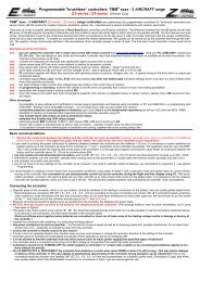
<strong>Programmable</strong> <strong>controllers</strong> TMM ® <strong>xxxx</strong> <strong>–</strong> 3, <strong>CAR</strong> - <strong>BOAT</strong> (<strong>EXPERT</strong>) (Version 3.20 and higher)<br />
for brushless sensorless motors<br />
Controllers TMM ® <strong>xxxx</strong> <strong>–</strong> 3, <strong>CAR</strong> <strong>–</strong> <strong>BOAT</strong> (<strong>EXPERT</strong> line) are outstanding bi-directional programmable <strong>controllers</strong> for brushless sensorless motors<br />
(BLCD motors) for car and boat models. It is possible forward / backward setup or one way setup. They are manufactured with the use of surface mounting from<br />
high-end components and are controlled by a very powerful processor. Controllers are ready for immediate use, no programming necessary. However, if you wish to set<br />
some parameters you may do so through a very simple process using transmitter, programming card UNI<strong>CAR</strong>D or PC. If PC is used for programming, it is essential to use<br />
USBCOM(+) module with supplied SW. USBCOM module is connected with controller using servocable. Controllers may be connected to the USBCOM(+) or to<br />
UNI<strong>CAR</strong>D module with the connection cable CC_02. The cable is inserted in a special ICS connector, which is a part of the controller. In this case it is not necessary<br />
to disconnect the controller from the receiver each time, which significantly simplifies the whole process. This allows to obtain some information about the last<br />
flight from the controller (such as average current in full throttle, peak current, etc.). Programmed parameters are saved permanently.<br />
Thanks to the high-tech TMM ® technology of MGM compro <strong>controllers</strong> feature number of outstanding properties which considerably eliminate the possibility of unwanted<br />
damage or destroy of motor, batteries and controller itself. Controllers also ensure the maximal efficiency with different kinds of motors. The revolution regulation is extremely<br />
fine - 1024 steps all the way to the full throttle. Starting is very fine. The MEGA BEC or S_BEC circuit (applies to versions with BEC) is also extremely powerful. All <strong>controllers</strong><br />
are Lipol compatible and watch over their minimal voltage.<br />
Maximum attention is paid to development which is in a continuous progress. SW update from this version up may be done through Internet using your computer<br />
and USBCOM++ module (USBCOM++ version must be 3.00 and higher), with CC_03 cable. It is not necessary to mail <strong>controllers</strong> with this (or higher) versions for<br />
SW update back to the manufacturer. See to USBCOM++ manual for details. The quality of products is under constant supervision in manufacture. Every controller goes<br />
through numerous tests. The final test of each controller is done under the controller’s full load.<br />
The <strong>controllers</strong> supported also RC sets with HRS modulation.<br />
Fast and easy to road or water:<br />
To ensure correct type of the controller for each set (batteries, motor and propeller) it is best to measure (recommended is a clamp A-meter) current drawn from batteries<br />
when connected to the load. It is necessary to carry out the measurement with the „hardest“ batteries intended for use in this set. This will prevent problems that might occur<br />
when the controller is overloaded (and batteries and motor as well). If you need to have power wires to battery longer than 30cm is it necessary to solder additional capacitors<br />
(same as in the controller) as close to controller (to + and <strong>–</strong> wires of the controller) as possible. They must be „very low ESR“, 105°C. For more info see www.mgmcompro.com<br />
technical advice section.<br />
Remember to ensure proper cooling of the controller, especially when working near limit parameters. It is not possible to control more than one motor with one controller.<br />
It is recommend to program the controller first, see page 4, 5, 11 and 12.<br />
1) How to connect the controller:<br />
� Opposite piece of the connector, which is on your accumulators, should be soldered to the leading-in conductors to the accumulator. Use only quality golden plated kinds.<br />
Recommend are MP JET 1.8mm, 2.5 or 3.5 mm acorrding to the type of controller and current. It is also possible to use golden plated <strong>controllers</strong> ∅ 4, resp. 2 mm or<br />
Schulze 3.5 mm (connectors are not interchangeable). MP JET connectors feature smaller transient resistance and also smaller dimensions. We recommend to put<br />
socket on the “-“ wire (black wire) of the controller and the plug on the “+” wire (red wire).<br />
to battery<br />
� Controllers for higher currents (60A and more) are manufactured in four designs. The first one is similar to that<br />
of aircraft <strong>controllers</strong> that is the controller is enclosed in shrinking sleeve with axial wires. The second design<br />
features is external coolers and third design is additional ribbed heat sinks (radiators) on both sides of controller<br />
(“CUBE” version - HCS_01 option). “CUBE” version is produced without power cables. On the controller are<br />
connectors sockets for plugs G3.5 only. Wires to battery and motor are connected using G3.5 plug connectors<br />
in socket 3.5 mm vertically to the controller <strong>–</strong> this design is much more preferable in term better cooling.<br />
Connectors G3.5 or wires with G3.5 connectors (on the controller side) are available as option.<br />
IT IS NO POSSIBLE SOLDER CABLES DIRECTLY TO CONTROLLER OUTLETS<br />
(for CUBE version) <strong>–</strong> it is need use G3.5 connectors !<br />
+ battery<br />
Last version is made with water coolers.<br />
Braking lights BL_04A<br />
ICS connector<br />
Braking lights BL_02A<br />
Braking lights connection<br />
<strong>–</strong> marking on capacitors<br />
<strong>–</strong> battery<br />
Battery and motor<br />
connection using<br />
G3.5 connectors<br />
(option)<br />
Design „CUBE“ with additional heat sinks, (option HCS_01) for 60A ESC and more<br />
ESC with Water coolers<br />
to motor<br />
2.5 mm 2 cable<br />
G3.5 connector plug<br />
G3.5 connector socket<br />
Braking lights is possible connect to <strong>controllers</strong> directly (option). Ta se rozsvítí, pokud auto brzdí (platí i pro automatickou brzdu v neutrálu). Světla jsou dostupná<br />
ve dvou modifikacích <strong>–</strong> se dvěma vysoce svítivými LED (BL_02A ) a se čtyřmi vysoce svítivými LED (BL_04A ).<br />
ESC with External coolers<br />
to motor<br />
ESC with External cooler and Fan
2 / 12 <strong>CAR</strong> / <strong>BOAT</strong> <strong>EXPERT</strong> V3.20 and higher<br />
� Receiver and antenna should be placed as far as possible from the controller, the batteries and power leads.<br />
� NOTICE, reversal of poles on wires to the batteries will destroy the controller ! (This however, may not show immediately, but in some later starts)<br />
� The leads to the motor (yellow wires marked “A”, “B”, ”C”) should be soldered directly to the motor or it is also possible to use the connectors mentioned above. If you decide<br />
to use connectors, this time solder sockets to the controller leads !<br />
Short cut of these wires together (when batteries are connected) or short cut of these wires to the feeding voltage results in damage or destroy of the controller<br />
!<br />
� After the connectors are soldered it is necessary to isolate them, for example with heat shrinking sleeve !<br />
� Use power conductors as short as possible <strong>–</strong> it is better for minimum weight and for minimum interference<br />
� Connect the controller to throttle channel on the transmitter !<br />
� If motor runs in an opposite direction than desired, swap any two motor phases<br />
� It is necessary to cool the controller in operation with flowing air. Do not prevent the cooling air to get to the controller (e.g. by packing it in foam).<br />
� The controller informs about overload and overheating acoustically (motor beeping) and also through LED.<br />
� It is not allowed to feed the controller from any other source (such as mains power supply) than specified types of accumulators!!!<br />
� The switch of the controller is connected in such way that even if it gets damaged the BEC will be still functioning.<br />
The controller is switched on by TURNING OFF the switch (applies to “s” version with switch) or by connecting batteries (applies to versions without switch).<br />
� Do not switch off or disconnect the controller from batteries when motor runs or when it is still turning <strong>–</strong> that may lead to damage or destroyed of controller !!!<br />
Connection of the controller to RC equipment:<br />
Switch („s“ version)<br />
a) BEC version b) OPTO version<br />
Main<br />
battery<br />
- batt.<br />
+ batt.<br />
receiver<br />
Throttle channel<br />
channels xx<br />
<strong>–</strong><br />
controller<br />
+<br />
A<br />
B<br />
C<br />
servo<br />
servoconnector<br />
Switch (only „s“ version)<br />
motor<br />
LED on the bottom side<br />
ON position<br />
(open contact)<br />
„OFF position“<br />
Control pulses (orange)<br />
+5 V BEC voltage (red)<br />
ground (minus), brown<br />
to the motor<br />
SECURITY WARNING:<br />
Always disconnect the accumulators when not operating the model !!! Do not leave model with connected accumulators unattended !!! Please notice<br />
that running motor with propeller is very dangerous !!! Do not charge batteries when connected to the controller !!!<br />
If the controller is connected to batteries do not stay in the reach of the propeller !!!<br />
� NOTICE, reversal of poles on wires to the batteries will destroy the controller ! (This however, may not show immediately, but in some later starts or flights)<br />
� Short cut of these wires together (when batteries are connected) or short cut of these wires to the feeding voltage results in damage or destroy of the controller<br />
!<br />
� Make sure that the motor is in a good condition. A faulty or damaged motor (mechanical damages, shortcuts on winding, etc.) may cause damage or destroy of<br />
the controller as well as the feeding cells.<br />
Main<br />
battery<br />
receiver<br />
Throttle channel<br />
channels xx<br />
Free channel<br />
No disconnect for<br />
„OPTO“ versions<br />
<strong>–</strong><br />
+<br />
Switch („s“ version)<br />
controller<br />
A<br />
B<br />
C<br />
servo<br />
receiver’s<br />
battery<br />
Note:<br />
(for BEC versions only !!!)<br />
If you need to feed the receiver or servos<br />
from some other source carefully<br />
take out the central core of the servo<br />
cable connector. The taken out core of<br />
this conductor must be properly insulated.!<br />
Development, manufacture, service: Tel.:+420 577 001 350, fax:+420 577 001 348<br />
MGM compro, Ing. G. Dvorský, E-mail: mgm@mgm-compro.cz<br />
Sv. Čecha 593, 760 01 Zlín, Czech Republic Info: www.mgm-compro.com<br />
motor
MEGA BEC: <strong>controllers</strong> up to 12 cells are equipped with BEC.<br />
The BEC can hold peak currents up to 4A and loss power loads which<br />
are significantly big but has its limits. It may not exceed 20W. It is<br />
possible to determine for example current which may be drawn from<br />
BEC under given load and voltage and also find out for how long from<br />
the graph. The power losses of the BEC warm the controller up. It is<br />
necessary to remove the generated heat by airflow. If the BEC is<br />
loaded with the power loss >5W pauses for cooling are necessary so<br />
that the average power loss is ≤ 5W. REMEMBER that the controller<br />
is also heated by the power loss generated in the motor part !<br />
Power loss of 5V BEC: (UBATT <strong>–</strong> 5V) × current I<br />
(it is favorable to use axis with difference of voltages UBATT <strong>–</strong> UBEC)<br />
Example: (see graph) if voltage of batteries is 10,5V it is possible to<br />
draw current of 1,8A continuously for 10 sec. when the power loss of<br />
BEC is 10W. If the load would only take 5 sec. the power loss may be<br />
15W and it is possible to draw current up to 2,7A.<br />
Only version “MEGA BEC+” features long lasting shortcut<br />
protection!<br />
S BEC (switched BEC): TMM <strong>controllers</strong> for higher loads<br />
and voltage up to 6 Lipol / 18 Nixx use switched BEC (see parameter<br />
table page 7). Such BEC is favorable in operation with<br />
higher input voltage as the losses are lower or to put it differently,<br />
it enables to draw significantly higher currents even from higher<br />
input voltage. Load characteristic differ significantly from those of<br />
linear BECs. However, also this type of BEC has its limits even<br />
though it is much less dependent on input voltage than linear<br />
type of BEC.<br />
Current load normally decreases with rising temperature. Maximal<br />
time for which a given current may be drawn is shown in the<br />
graph and it also decreases with rising temperature. Also this<br />
type of BEC must be cooled by airflow when drawing higher currents.<br />
With BEC it may endure a short time short-circuit on output without<br />
damage.<br />
It is possible use powerful digital servos also.<br />
Example: 6 Lipol cells (that is 25.2 V charged, 23 <strong>–</strong> 24 V under<br />
load). The servos draw 3A. With BEC it endures this current for<br />
45 sec. without cooling. In real operation such situation is rare;<br />
the situation is usually more favorable as the servos are not<br />
working continuously and do not have a continuous draw all the<br />
time <strong>–</strong> in such intervals without load or with a small load BEC is<br />
cooled.<br />
5V<br />
Load 5,94 A at<br />
the time 3,7 sec.<br />
2,7 A<br />
5,94 A 4,4 A<br />
cooling<br />
0,53 A<br />
cooling<br />
Max. current „I“ of the BEC [A]<br />
3 / 12 <strong>CAR</strong> / <strong>BOAT</strong> <strong>EXPERT</strong> V3.20 and higher<br />
4A<br />
3A<br />
2A<br />
1A<br />
0<br />
Difference<br />
UBATT -UBEC<br />
Max. current „I“ demand from „S BEC“<br />
7A<br />
6A<br />
5A<br />
4A<br />
3A<br />
2A<br />
1A<br />
0<br />
2,2 A<br />
2,7 A<br />
1,8 A<br />
BEC load<br />
10,5V<br />
RESTRICTED AREA<br />
5 6 7 8 9 10 11 12 13 14 15 16 17<br />
1<br />
2<br />
3<br />
Example of S BEC load.<br />
4<br />
5 6 7 8 9 10 11 12<br />
When exceeding the maximal limits of current or power losses, BEC may be destroyed and the model may be uncontrollable !<br />
Please, notice that servos loaded with the control surfaces (rudder, ailerons etc.) in the air draw many times more current than when you move them on the ground !<br />
6<br />
Load capability of the „S BEC“<br />
8 10 12 14 16 18 20 22 24 26<br />
UBATT. [V]<br />
max. 25,5V<br />
Power loss<br />
of the BEC:<br />
20 W / 1 sec.<br />
15 W / 5 sec.<br />
10 W / 10 sec.<br />
Note: be careful when determining the range of the set, especially when using more batteries <strong>–</strong> in case of signal loss servos might turn to their maximum which would<br />
cause significant rise in drawn current. This might lead to a power overload of BEC with all its consequences. The danger is lower with receivers which set a defined<br />
servo position when loss of signal occurs.<br />
CONNECTING BEC: if two <strong>controllers</strong> are used in a model, BEC can be connected in two ways:<br />
a) if each controller is switched on separately (by switch or by connection to batteries ) it is possible to use only one BEC <strong>–</strong> it is necessary to take out the middle core of<br />
servoconnector of one controller<br />
b) if a simultaneous switch on of both <strong>controllers</strong> is ensured (connected „+“ and „<strong>–</strong>“ wires of both <strong>controllers</strong>, without switches) both BECs can stay connected. This will<br />
also increase allowed current and power loads (aprox. twice) of BECs connected in this way.<br />
5 W cont.<br />
UAKU [V]<br />
5 sec.<br />
10 sec.<br />
15 sec.<br />
25 sec.<br />
45 sec.<br />
120 sec.<br />
continuous
4 / 12 <strong>CAR</strong> / <strong>BOAT</strong> <strong>EXPERT</strong> V3.20 and higher<br />
2) Programming / obtaining data from controller using PC:<br />
If you wish to program using PC or obtain data from the controller, USBCOM / USBCOM+ module (order number 86.20001, resp. 86.20002) are necessary<br />
for connecting the controller to the PC. Also a SW (part of the communication module) is needed. It is necessary use connecting the USBCOM(+) module and<br />
CC_02 cable into ICS connector, it is not necessary to disconnect the controller from the receiver upon each programming (data reading-out).<br />
Programming the controller using PC will make the process of setting parameters easier and clear. Obtaining data about last flight will help determine<br />
an optimal power of your model so that both power and technical possibilities of your controller / motor / batteries are fully used and that the possibility<br />
of overloading them is avoided at the same time. If using <strong>controllers</strong> with BEC keep the transmitter turned on while programming <strong>–</strong> servos will not jerk when<br />
the controller is turned on.<br />
To install, and obtain data from controller and program controller please refer to instructions in manual for your communication module.<br />
The overview of data that can be obtained from controller (from last flight):<br />
- average current at full throttle in stable state<br />
- maximal peak current<br />
- end voltage of battery<br />
- maximal temperature of the controller<br />
- min. throttle position (full brake)<br />
- neutral throttle position<br />
- max. throttle position<br />
- max. motor revolutions<br />
PC window:<br />
Type and version of the controller<br />
are recognized automatically<br />
min. (full throttle backward) and<br />
max.( full throttle forward) throttle<br />
position and neutral<br />
<strong>–</strong> read out/ change of value<br />
Setting number of the motor<br />
poles and gear ratio<br />
Measured values area<br />
3) Programming by card UNI<strong>CAR</strong>D:<br />
Fast setting of default parameters<br />
connector ICS<br />
connector on the cable<br />
right orientation<br />
All parameters may be easily set using programming card UNI<strong>CAR</strong>D. Connecting via CC_02 cable into ICS<br />
connector, it is not necessary to disconnect the controller from receiver before each programming.<br />
If using <strong>controllers</strong> with BEC keep the transmitter turned on while programming <strong>–</strong> servos will not jerk when<br />
the controller is turned on.<br />
Orange (data)<br />
TMM <strong>xxxx</strong>-3, <strong>CAR</strong> / <strong>BOAT</strong> connector ICS<br />
Connection cable CC_02<br />
For more detail see the programming card manual.<br />
CC_02<br />
Brown<br />
(ground, minus)<br />
Recommended procedure for programming by UNI<strong>CAR</strong>D or by PC: (unnecessary for BASIC mode)<br />
CC_02<br />
Connection cable CC_02<br />
connector on the cable, bottom view - the ICS<br />
connector may not be connected in this way<br />
Parameters read out from controller are displayed<br />
here + changes of parameters can be done here<br />
using mouse<br />
UNI<strong>CAR</strong>D<br />
to USBCOM<br />
I) first teach the controller the real limit boundaries of your transmitter <strong>–</strong> this is done only for the first time or when using new transmitter or receiver<br />
- that is “minimal” and “maximal” throttle positions and “neutral”. This is done by programming using transmitter:<br />
a) turn on the transmitter and move the throttle to maximal position forward,<br />
b) turn the controller on, wait 10 seconds for 3 motor beeps, then<br />
c) move the throttle to maximal position backward (full brake), 1 beep by the motor and<br />
d) move the throttle to neutral, 2 beeps, and then turn the controller off.<br />
The controller has now saved the positions (permanently until possible next programming).<br />
II) when the controller has saved the real limit boundaries (min and max throttle positions) of your RC set, all the other parameters may be set anytime using<br />
the programming card UNI<strong>CAR</strong>D or by connecting the controller to the PC using USBCOM(+) and setting the parameters with mouse (utility “Controller“).<br />
If you wish to set the parameters using transmitter, do not turn the controller off in d) above but continue programming (for details see page 5.).<br />
Automatic tuning Setup<br />
Shift to other parameters
4) Programming with transmitter:<br />
5 / 12 <strong>CAR</strong> / <strong>BOAT</strong> <strong>EXPERT</strong> V3.20 and higher<br />
All programming can be done thought transmitter and receiver with which the controller will run. After programming the data will be saved (until possible next programming)<br />
and the controller must be switched off. After switching it on again it is ready to ride with the newly set parameters. If after switching on, the throttle<br />
stick is not in the neutral position the controller waits for it to get there (safety precaution) <strong>–</strong> if the throttle is in its neutral position you may take off immediately. If<br />
transmitter or receiver is changed for a different one, it is recommended to do the programming again <strong>–</strong> it is enough to start the programming mode so that new<br />
parameters of control signal are saved (switch on with full throttle forward, wait 3 beeps, move to full throttle backward, 1 beep, move to neutral, 2 beeps, controller<br />
switch off).<br />
How to program the desired “value” in parameter you are setting (basic procedure in each parameter):<br />
Move the throttle to the max. throttle backwards position, LED will be blink 1× (once) and motor beeps 1×. Move throttle back to neutral position, LED will be blink 2× and motor<br />
beeps twice. Repeat this procedure (max. throttle backwards position <strong>–</strong> neutral) as many times as is the number of parameter (according to the table) you wish to set.<br />
For example: for setting the number 4 in parameter D (that is timing 15°) repeat the whole procedure (max. throttle backwards position <strong>–</strong> neutral) 4x (you certainly have to<br />
be in parameter D).<br />
The programming of each parameter will be finished when you move the throttle from neutral position to the max. throttle forward position<strong>–</strong>LED will be blink 3× and motor<br />
will beep 3×, then move the throttle back to neutral position, LED will be blink 2× and motor will beep 2× <strong>–</strong> the parameter is programmed to the value you have chosen and<br />
saved (this sequence is marked as “ENTER”). This also automatically gets you to next parameter. After the last programmed parameter the controller must to be always<br />
switched off first !<br />
It is not obligatory to program all parameters <strong>–</strong> it is possible to switch the controller off after any parameter which is correctly finished by ENTER sequence. The<br />
following parameters will not be changed and all the preceding will be saved.<br />
If you do not wish to change some parameter (you wish to preserve its last value) you directly skip this parameter by ENTER sequence. The parameter value stay as it<br />
was before and the controller will get to the next parameter programming.<br />
EASY return to default settings: start the controller with full throttle forward as if you were going to program. After 10 seconds the controller will beep 3 times. Do<br />
not move the throttle to break position but wait another 5 seconds for 4 beeps. After those, move the throttle max. throttle backward position (in 3 seconds) and<br />
the default setting is resumed and BASIC mode is set. If the throttle is not moved to break position in the 3 seconds time, the setting will not change and controller<br />
waits for switch off.<br />
The programming itself:<br />
1) Turn the transmitter on with throttle stick in max. throttle forwards position !<br />
2) Turn on the controller. After 10seconds the controller will beep 3 x and LED will blink and stay turned on. Now you have 3 seconds to move the throttle to max throttle<br />
backwards position (full brake). If in this time limit you do not put the throttle in min position the programming process will end and the controller will be turned off. Its<br />
next operation is possible after switching off and then turning on by switch (disconnecting and connecting of batteries). If you put the throttle to full brake in<br />
this time limit, the motor will beep 1× and the LED will be blink 1×. Move throttle to neutral position, motor will beep 2× and the LED will be blink 2×. Now you are in the<br />
programming mode and may start to program parameters according to the procedure described above.<br />
3) Parameter A <strong>–</strong> mode choice: <strong>CAR</strong> / <strong>BOAT</strong> / Automatic Tuning<br />
I) You wish to set <strong>CAR</strong> mode forward / backward:<br />
Move the throttle to max throttle backwards position (full brake) position, LED will be blink 1× and the motor will be beep 1×. Move throttle back to neutral position,<br />
LED blink 2× and motor will beep 2×. This choice will be confirmed by moving the throttle from neutral to max throttle forwards position <strong>–</strong> LED will be blink 3× and<br />
motor will beep 3×. Then move back to neutral position and LED will be blink 2× and motor will beep 2×. It is set <strong>CAR</strong> mode and you may go to set next parameters.<br />
II) You wish to set <strong>BOAT</strong> mode forward / backward:<br />
Move the throttle to max throttle backwards position (full brake) position, LED will be blink 1× and the motor will be beep 1×. Move throttle back to neutral position,<br />
LED blink 2× and motor will beep 2×. This sequence make two times (you must set number “2”). This choice will be confirmed by moving the throttle from neutral<br />
to max throttle forwards position <strong>–</strong> LED will be blink 3× and motor will beep 3×. Then move back to neutral position and LED will be blink 2× and motor will beep 2×. It<br />
is set <strong>BOAT</strong> mode and you may go to set next parameters.<br />
III) You wish to set <strong>CAR</strong> mode one way:<br />
Move the throttle to max throttle backwards position (full brake) position, LED will be blink 1× and the motor will be beep 1×. Move throttle back to neutral position,<br />
LED blink 2× and motor will beep 2×. This sequence make three times (you must set number “3”). Confirm by ENTER.<br />
IV) You wish to set <strong>BOAT</strong> mode one way:<br />
Move the throttle to max throttle backwards position (full brake) position, LED will be blink 1× and the motor will be beep 1×. Move throttle back to neutral position,<br />
LED blink 2× and motor will beep 2×. This sequence make four times (you must set number “4”). Confirm by ENTER.<br />
V) Automatic Tuning mode:<br />
Move the throttle to max throttle backwards position (full brake) position, LED will be blink 1× and the motor will be beep 1×. Move throttle back to neutral position,<br />
LED blink 2× and motor will beep 2×. This sequence make five times (you must set number “5”). Confirm by ENTER. No switch OFF controller! After<br />
“ENTER” beeps you hear signalizing of this mode: “beep <strong>–</strong> beep <strong>–</strong> beeeeeep”. Now, a ride under full throttle forward should be done.<br />
4) parameter B <strong>–</strong> brake / deceleration:<br />
set according to the “How to program the desired value in parameter you are setting” (see above) set the desired value and move to next parameter<br />
5) parameter C to J:<br />
Set the desired value according to the table for each parameter. End and save each parameter by ENTER sequence which will also move to the next programmable<br />
parameter. Parameters which you do not wish to change may be skipped by directly performing ENTER sequence. After programming the last desired parameter the<br />
programming is finish by performing ENTER.<br />
6) Turn of controller !<br />
Development, manufacture, service: Tel.:+420 577 001 350, fax:+420 577 001 348<br />
MGM compro, Ing. G. Dvorský, E-mail: mgm@mgm-compro.cz<br />
Sv. Čecha 593, 760 01 Zlín, Czech Republic Info: www.mgm-compro.com
Description of parameters in the programming mode:<br />
6 / 12 <strong>CAR</strong> / <strong>BOAT</strong> <strong>EXPERT</strong> V3.20 and higher<br />
Parameter A <strong>–</strong> mode choice: “<strong>CAR</strong>” mode for cars, “<strong>BOAT</strong>” mode for boats + „Automatic Tuning “ (for automatic controller optimization for a specific car).<br />
In this version it is possible forward / backward setup or one way setup also.<br />
<strong>CAR</strong> mode forward / backward [A1]: If the car is at standstill, then by moving the throttle from neutral the car will go backward or forwards. If the car is moving<br />
then by moving the throttle backwards the car will brake. The brake is proportional, that means the further the throttle is from neural the more<br />
intensive the brake is. The intensity of braking in the max throttle position may be set in parameter “B”. When braking the car will stop, and not<br />
start moving backwards until you move the throttle to neutral and then again backwards. Connected braking lights are turned on when braking.<br />
<strong>BOAT</strong> mode forward / backward [A2]: in this mode the parameter „B“ sets the speed in which the motor revolutions are reduced from maximum to the full<br />
stop. The direction of motor revolutions is reversed immediately upon moving the throttle the opposite way. The speed of slowing down and starting<br />
up is set in parameters „B“ and „C“.<br />
One way setup (forward only) [A3, A4]: when you move throttle from neutral to back position, motor is only braking, no go to reverse of rotation.<br />
!!! Automatic Tuning [A5]: this specialized mode serves for automatic controller performance optimization for your car. It is recommended to<br />
carry out during the first ride and after any change in the car (different motor, different pinion, number of cells, type of cells…).<br />
When is set this mode (from transmitter, UNI<strong>CAR</strong>D or PC), controller signalizing this state by „beep <strong>–</strong> beep <strong>–</strong> beeeeeeep“. Don’t controller switch<br />
off, only disconnect CC_02 cable form the controller.<br />
After the „settings“ ride which is done immediately after programming (no switch off controller !!!) into mode „Automatic Tuning Settings“ the<br />
controller automatically goes back to earlier setting (<strong>CAR</strong> mode forward / backward or one way <strong>–</strong> A1 up to A4). This „settings“ ride is done with all<br />
the earlier set parameters. During this ride, the car must go on full throttle forward at least for a while, the best is form the beginning <strong>–</strong> then the<br />
optimized setting is used even for this ride. „Automatic Tuning Setting“ is not obligatory, the car will run, however, the parameters B, I and J will<br />
not be optimized before you go on the full throttle.<br />
Parameter B <strong>–</strong> brake: <strong>CAR</strong> mode: enables to set 8 grades of intensity of proportional brake in the max. throttle position. Set according to your needs. If you<br />
need automatic brake in neutral position of throttle, set parameter „J“. For its optimal performance it is recommended to run Automatic Tuning,<br />
mode A5.<br />
<strong>–</strong> deceleration: <strong>BOAT</strong> mode: enables to set the speed of deceleration in 5 grades, Set according to your needs.<br />
Parameter C <strong>–</strong> acceleration: enables to set acceleration (acceleration speed of motor) in 5 steps. Set according to your needs.<br />
Parameter D <strong>–</strong> timing: here you may choose (and experiment with) 5 different timings. The sixth possibility is automatic timing which is strongly recommended<br />
because it ensures optimal setting and maximal efficiency. While using the definite values of timing and higher timing you may rise the motor<br />
revolution or the twisting moment a bit but always at the expense of lowering the efficiency. If you wish to have higher revolutions it is better to<br />
use different motor or more cells because lower efficiency cannot be made up for. High value of timing may in unsuitable combination with some<br />
motors damage the controller!<br />
Motor with high inductance: for example AXI 4120, 4130…, some “LRK” motors, lots of motors from CD ROMs, etc.) setup timing 5° or 10° or 15, automatic<br />
timing may not be optimal. The need of setting different timing can be easily recognized <strong>–</strong> motor looses synchronization for higher loads.<br />
Parameter E <strong>–</strong> controller behavior when batteries are getting low: This parameters sets the <strong>controllers</strong> behavior at moment when the voltage on discharging<br />
curve of batteries gets to the point when controller starts to preserve the remaining energy for BEC. You may set continuous motor<br />
revolutions reduction or an immediate cut off (with the possibility of start when you lower the throttle to neutral). This depends on pilots customs.<br />
Both behaviors are quite alike regarding the residual energy.<br />
Race mode: In race mode, the motor will be stopped when voltage of batteries drops below ca 4V, number of cells, their condition or current is not taken into<br />
consideration. After throttling down to neutral, the operation may be resumed. This mode is quite harsh on accumulators, particularly for those<br />
with more cells !!! Current fuse is disabled (that means it does not check maximal current !!!), the thermal fuse is set to 105°C. Warranty does not<br />
apply to a possible damage of controller when operating under this mode.<br />
Parameter F <strong>–</strong> battery: choice of the battery type, NiCd, NiMH or Li-Ion, Li-Pol<br />
Parameter G <strong>–</strong> range of the neutral zone: There exists a zone evaluated by the controller as „the neutral“. Here the motor is not fed, the brakes are or are<br />
not applied automatically, in case of an overcharge normal operating mode is resumed. This parameter may be changed according to your needs<br />
and requirements in the extent of ca 3 up to 20% of the full deflection of the throttle stick. The zone which is too narrow may be not evaluated reliably<br />
and the one which is too wide narrows the zone of step less control.<br />
Parameter H <strong>–</strong> automatic correction of the neutral after each switching-on: If this parameter is not switched on, the position of the neutral is evaluated<br />
exactly according to the setup within the scope of basic programming. If this parameter is switched on, the correction to the throttle stick current<br />
neutral position is carried out after each controller switch-on. It can be used in such cases as are those when you easily (and unintentionally)<br />
move the trim thus changing the centre of the neutral. There is no need to carry out the basic programming again - upon the following switch-on<br />
of the controller the position of the neutral is set automatically. When switching the controller on, pay heed to the following - the transmitter must<br />
already be switched on and the throttle stick moved to the neutral position.<br />
Parameter I <strong>–</strong> Freewheel: Operation without the switched on freewheel can be compared to a common car with an engaged gear. If you throttle down, the car<br />
gets braked to the value of a throttle stick new position. If you quickly move the throttle stick to the neutral position, the car finishes running due to<br />
inertia as if you were driving a common car without the engaged gear. If the freewheel is switched on, the motor gets disconnected (and does not<br />
brake) on each quicker dropping the throttle to a lower value (of course incl. the neutral); the motor gets disconnected until the car due to inertia<br />
slows down to the speed corresponding to the throttle stick new position. Then the motor gets fed again. Actually it is an electronic analogy of<br />
mechanical freewheels. The electronic analogy directly affects the motor and thus all driven axles. Operation with a switched on freewheel is<br />
suitable for roads and races, while with a switched off freewheel it is suitable for off-road (in the „car“ mode only). For its optimal performance it is<br />
recommended to run Automatic Tuning setting, mode A5. (This parameter is set only in mode „<strong>CAR</strong>“)<br />
Parameter J <strong>–</strong> automatic brake in neutral: Braking intensity in the neutral position is set in 7 steps - automatic brake for cars. It is similar to braking with the<br />
use of a motor in the real car. You can OFF this brake also. For its optimal performance it is recommended to run Automatic Tuning setting,<br />
mode A5. (This parameter is set only in mode „<strong>CAR</strong>“)<br />
Programming table:<br />
Para-<br />
meter<br />
Value of parameter �<br />
0<br />
(direct ENTER)<br />
1 2 3 4 5 6 7 8<br />
A Mode choice next parameter<br />
„<strong>CAR</strong>“ mode<br />
forward / backward<br />
<br />
„<strong>BOAT</strong>“ mode<br />
forward / backward<br />
<br />
„<strong>CAR</strong>“ mode<br />
one way<br />
I=><br />
„<strong>BOAT</strong>“ mode<br />
one way<br />
I=><br />
Automatic<br />
Tuning<br />
- - -<br />
B<br />
Brake (car)<br />
Deceleration (boat)<br />
next parameter<br />
Without brake<br />
0,13 sec.<br />
Light 1<br />
0,26 sec.<br />
Light 2<br />
0,39 sec.<br />
Medium 1<br />
0,65 sec.<br />
Medium 2<br />
1,3 sec.<br />
High 1<br />
1,8 sec.<br />
High 2<br />
2,3 sec.<br />
Hard 1<br />
3,0 sec.<br />
C Acceleration (0 to 100%) next parameter 0,13 sec. 0,26 sec. 0,39 sec. 0,65 sec. 1,3 sec. 1,8 sec. 2,3 sec. 3,0 sec.<br />
D Timing next parameter automatic 5° 10° 15° 20° 25° - -<br />
E<br />
Behavior when battery<br />
voltage going down<br />
F Battery type *) next parameter NiCd, NiMH<br />
next parameter Slow reduce rpm Motor cut off RACE MODE - - - - -<br />
Li-Ion, Li-Pol<br />
2 cells<br />
G Range of the neutral zone next parameter 3% 6% 9% 12% 15% 18% 21% 24%<br />
H<br />
Automatic correction of the<br />
neutral<br />
next parameter NO YES - - - - - -<br />
I Freewheel next parameter NO YES - - - - - -<br />
J Automatic brake in neutral End of program. NO Very Light Light Medium 1 Medium 2 High Hard<br />
Notice: Default setting is bold.<br />
*) maximal number of Lipol cells for a controller is given in technical specifications for each controller (page 8), (that means for 12032 ESC it is 10 cells)<br />
Li-xxx<br />
3 cells<br />
Li-xxx<br />
4 cells<br />
Li-xxx<br />
5 cells<br />
Li-xxx<br />
6 cells<br />
Li-xxx<br />
7 cells<br />
Li-xxx<br />
8 cells<br />
Very<br />
Hard
Advantages of TMM ® <strong>controllers</strong> <strong>CAR</strong> / <strong>BOAT</strong> Expert line:<br />
7 / 12 <strong>CAR</strong> / <strong>BOAT</strong> <strong>EXPERT</strong> V3.20 and higher<br />
TMM <strong>controllers</strong> feature number of outstanding qualities which distinguish them from regular <strong>controllers</strong>. Those are:<br />
a) easy programming (setting) important parameters using transmitter, programming card UNI<strong>CAR</strong>D or PC (for more information see „Programming“ part)<br />
b) programming using ICS connector <strong>–</strong> it is not necessary to disconnect the controller from the receiver upon each programming (applies only to <strong>EXPERT</strong>+)<br />
c) important data measured in operation of controller may be obtained using PC <strong>–</strong> great for optimal power setting<br />
d) outstanding protection and management of Lipol/Lion (very important ) and NiCd/NiMH batteries<br />
e) perfect masking of signal interference and losses<br />
f) extremely fine throttle step (1023 steps)<br />
g) very soft starts<br />
h) motor and controller overload protection<br />
i) very large settings possibilities, include Automatic Tuning<br />
j) very powerful BEC (MEGA BEC or switching BEC)<br />
k) all <strong>controllers</strong> is made with switch also (safe connection)<br />
Protective and safety mechanisms of TMM ® <strong>controllers</strong>:<br />
Accumulators are protected in four ways.<br />
1) Firstly, due to the use of automatic current fuse (ACF) the possibility of current overload of accumulators (and their possible damage) even at crisis points is significantly<br />
reduced.<br />
2) Secondly, the used system of intelligent power reduce (IPR) always ensures through measurements of number of voltage, currents, accumulator condition and calculations<br />
an optimal point of starting continuous reduction of motor performance (or the point when motor is switched off <strong>–</strong> according to the setting of parameter F”) so that<br />
accumulator cells do not get extremely discharged <strong>–</strong> which is very important specially for Lipol cells.. This, not mentioning other advantages, reduces the possibility of<br />
reversal of poles of lower cells (applies mainly to NiCd / NiMH cells).<br />
3) This system at the same time enables retaining defined energy for BEC (perfect RPC) in <strong>controllers</strong> that have BEC which is of great significance for flying models<br />
(a crash due to running out of energy for receiver and servos can be avoided) . The amount of residual energy can be user set.<br />
4) the automatic current reduce (ACR) due to which a drop in voltage for BEC under extremely big current load (for every given controller) while motor starts does not occur.<br />
When switching (reducing power) the motor off at solid boundary as it is with regular <strong>controllers</strong> (a) there is only very little energy remaining for BEC, particularly<br />
for 8 or more Nicd / NiMh cells in battery pack. This mainly applies for <strong>controllers</strong> with the switching of one boundary at (5.5V). The better accumulators are used<br />
the less energy (time) is left to land (standard ESC).<br />
Comparing to this, TMM (b) ensures the remaining energy to be big enough; it is also possible to modify its size according to user needs (bigger for gliders). This<br />
energy is certainly insignificant as long as duration of running the motor is concerned, but it is very significant for feeding BEC.<br />
Graphs below show situation with 3 Lipol cells. In graph a] a regular controller situation is depicted <strong>–</strong> controller is Lipol compatible and has a solid boundary of<br />
switching of. In graph b] a behavior with TMM ® controller is shown <strong>–</strong> with a boundary on a discharging curve of inner voltage of battery.<br />
a) standard <strong>controllers</strong> determine for Lipol battery<br />
b) TMM<br />
U<br />
Battery voltage for current:<br />
® <strong>controllers</strong>, setting for Lipol battery<br />
U<br />
Battery voltage for current:<br />
Cut off voltage:<br />
4.2V<br />
cell<br />
(12.6V)<br />
0.5C 2C<br />
Residual energy for<br />
BEC is very depend on<br />
the actual current<br />
6C 10C<br />
Cut off voltage:<br />
3.6V / cell (10.8V)<br />
3.3V / cell (9.9V)<br />
3.0V / cell (9.0V)<br />
2.7V / cell (8.1V)<br />
60% 80% 100% capacity<br />
95% [mAh]<br />
Regular <strong>controllers</strong> (even Lipol compatible) have either a solid switching off<br />
voltage (for example 3V per cell) or it is possible to set this value. For example<br />
for set boundary 3V per cell the controller is switch off or it starts to reduce revolutions<br />
when this value is reached no matter how big the drawn current is. This<br />
means that the residual energy significantly changes according to a instantaneous<br />
current load of batteries (and also according to inner resistance<br />
of the cells] from 0 to 95 % - depending only on the set voltage boundary. If the<br />
example on the graph above is considered with a set boundary of 3V per cell<br />
the controller will switch off when drawn current is 10C when there is still 40% of<br />
energy still left, while for 2C current when only 5% of energy is left. For boundary<br />
of 3.3V per cell the controller would switch off for currents of 10C when only<br />
few percent of energy were consumed while for 2C after 92% of energy would<br />
be consumed..<br />
The <strong>controllers</strong> efficiently mask interference and drop-outs up to 1,5 sec. When long-lasting drop-outs or interference occur the controller slowly reduces motor revolutions.<br />
After the signal is resumed the controller continuously gets to the requested power. Long lasting drop out of signal (or its absence) is indicated acoustically by motor as<br />
well as by LED. This can be used for example when searching for lost model.<br />
Without the proper signal from the transmitter (e.g. transmitter is turned off), the motor neither jerks nor runs but is at standstill<br />
Thermal fuse of the controller is set to 90°C when performance is reduced to ca 60%. After cooling off (even in flight) the reduction is disabled. After switching on, the<br />
temperature above 70°C is monitored; if the temperature is higher the controller does not start. New start is possible only after the controller temperature falls.<br />
(12.6V)<br />
WARNING :<br />
You risk destroying the controller for:<br />
� connecting more battery cells to the controller than the max. number specified in the technical data<br />
� reversing connections to the accumulator<br />
� shortcutting of wires to motor when batteries are connected<br />
� changing motor and accumulator outlets<br />
� overloading of the BEC with bigger currents or bigger power loss than is specified in technical data<br />
� water in the controller (except for „hydro“ versions“)<br />
� metal objects in the controller (screwdrivers, wires, etc.)<br />
� disconnecting the controller from batteries or turning off the controller while motor is running (or still turning)<br />
4.2V<br />
cell<br />
0.5C 2C 6C 10C<br />
Defined residual<br />
energy for BEC<br />
3.8V / cell<br />
75% 90% 100%<br />
95%<br />
3.7V / cell<br />
(Starting point<br />
of reduce motor<br />
power)<br />
3.6V / cell (10.8V)<br />
3.3V / cell (9.9V)<br />
3.0V / cell (9.0V)<br />
capacity<br />
[mAh]<br />
TMM ® <strong>controllers</strong> handle the situation quite differently. The switching off voltage is<br />
always recalculated into „inner“ voltage of the battery <strong>–</strong> therefore is independent on<br />
both drawn current as well as inner resistance of the accumulator. This means the<br />
set residual energy is always the same and does not depend on currents and<br />
inner resistance of battery. Batteries are then always discharged to same level, regardless<br />
how big currents are drawn. The value of set residual energy is therefore<br />
only little dependent on the features of battery and the discharging current. For example<br />
for switching voltage 3.7V per cell controller switches off the motor or starts to<br />
reduce revolutions always after 90% of energy is used up no matter if the drawn current<br />
is 10Cor 2C. (The voltage of accumulator after switch of the current always rises<br />
to a value close to curve of 0.5V <strong>–</strong> this discharging curve is close to „inner“ voltage of<br />
battery. This curve describes how much the controller is discharged.
Operating data:<br />
8 / 12 <strong>CAR</strong> / <strong>BOAT</strong> <strong>EXPERT</strong> V3.20 and higher<br />
Temperature of the environment: 0°C to 40°C Number of regulation steps: 1024 / full throttle<br />
Motor controlling: PWM 8 kHz Max. rpm for 2 poles motor: 170 000 rpm<br />
Control signal: positive pulses 1,5 ± 0,5 ms, period 10 ÷ 30 ms<br />
User set parameters: see programming<br />
MEGA BEC+: 5V / max. 4,0 A (load capability see graph), input battery voltage = 6 <strong>–</strong> 17V<br />
S BEC (switching BEC) 5V / max. 6,0 A (load capability see graph), input battery voltage = 6 <strong>–</strong> 25.5V<br />
Power supply: from batteries only: NiCd, NiMH, Li-Ion, Li-Pol<br />
Suitable for motors: Mega AC, Model Motors, MP JET, PJS, Ůberall model, Hacker, Kontronik, LRK, Plettenberg, etc.<br />
for 2 to 20 pole motors of classical conception (rotor inside) and also for outrunners (rotor is on the outer side).<br />
Motors with extremely low inductance (for example TANGO from Kontronik, etc.) are no allowed to connection <strong>–</strong> need PWM 32 kHz.<br />
Cooling: for the best cooling of the <strong>controllers</strong> is possible add (from both sides) external heatsinks 50×31×5mm or 38×31×5 mm.<br />
Thickness increase about 6 mm only, weight increase about 6 gr. [short], or 10 gr. [long heatsink].<br />
Fan: In the case of poor cooling air flow it can be add small 5V fan (+8.5 gram) to the heatsink <strong>–</strong> cooling effect will be significantly higher.<br />
Water cooling: for boats with cooling occasion is available version with water cooling plates (as Race Boat types)<br />
ESC with external heatsinks HC_02 External heatsinks with fan ESC with external water-cooling HC_02<br />
Water proof: electronics does not like water and humidity. For a significant improvement of controller resistance against humidity and water, it is possible to have<br />
a special protecting coating applied as an option (marked WP). This however, does not mean that the controller is 100% waterproof and resistant<br />
against humidity, as well as it does not mean that it shall not be protected against water and humidity. The protection does not apply to saltwater<br />
(sea water) !<br />
TMM ® <strong>xxxx</strong>-3 <strong>EXPERT</strong> V 3.2x 1812-3 2512-3 3312-3 4412-3<br />
Dimensions [mm]: 28×25×6 28×25×6 36×28×6 36×28×6<br />
Dimensions (with external capacitor) [mm]: 44×25×6 44×25×6 51×28×6 51×28×6<br />
Weight incl. all conductors: 17 g 19 g 32 g 32 g<br />
Weight without power conductors (with servocable): 10 g 10 g 18 g 18 g<br />
No. of feeding NiCd/NiMH cells: 6 <strong>–</strong> 12 6 <strong>–</strong> 12 6 <strong>–</strong> 12 6 <strong>–</strong> 12<br />
No. of feeding Li-Ion / Li-Pol cells: 2 <strong>–</strong> 4 2 <strong>–</strong> 4 2 <strong>–</strong> 4 2 <strong>–</strong> 4<br />
Max. current (for full throttle): 18 A 25 A 33 A 44 A<br />
Max. current for 5 sec.: 23 A 30 A 40 A 55 A<br />
On-state switch resistance at 25 °C: 2×3,7 mΩ 2×3,1 mΩ 2×2,9 mΩ 2×1,2 mΩ<br />
Model: MEGA BEC+**) MEGA BEC+**) MEGA BEC+**) MEGA BEC+**)<br />
BEC voltage: 5 V 5 V 5 V 5 V<br />
Power conductors (90 mm): 1,0 mm 2<br />
1,5 mm 2<br />
2,5 mm 2<br />
2,5 mm 2<br />
JR gold connector, cables: 0,15 mm 2<br />
0,25 mm 2<br />
0,25 mm 2<br />
0,25 mm 2<br />
TMM ® <strong>xxxx</strong>-3 <strong>EXPERT</strong> V 3.2x 6018-3 8018-3 12018-3 16018-3 22418-3<br />
Dimensions [mm]: 50×31×15 50×31×15 50×31×18 50×31×21 50×31×20<br />
Dimensions (with external capacitor) [mm]: 65×31×15 65×31×15 65×31×18 65×31×21 65×31×20<br />
Weight incl. all conductors: 55 g 57 g 83 g 91 g 94 g<br />
Weight without power conductors: 40 g 42 g 52 g 60 g 63 g<br />
No. of feeding NiCd/NiMH cells: 6 <strong>–</strong> 18 6 <strong>–</strong> 18 6 <strong>–</strong> 18 6 <strong>–</strong> 18 6 <strong>–</strong> 18<br />
No. of feeding Li-Ion / Li-Pol cells: 2 <strong>–</strong> 6 2 <strong>–</strong> 6 2 <strong>–</strong> 6 2 <strong>–</strong> 6 2 <strong>–</strong> 6<br />
Max. current (for full throttle): 60 A 80 A 120 A 160 A 224 A<br />
Max. current for 5 sec.: 70 A 100 A 150 A 200 A 260 A<br />
On-state switch resistance at 25 °C: 2×1,0 mΩ 2×0,67 mΩ 2×0,44 mΩ 2×0,33 mΩ 2×0,20 mΩ<br />
Model: S BEC S BEC S BEC S BEC S BEC<br />
BEC voltage: 5V 5V 5V 5V 5V<br />
Power conductors 90 mm (120 mm for 4 mm 2 ): 2,5 mm 2 2,5 mm 2<br />
4 mm 2 *) 4 mm 2 *) 4 mm 2 *)<br />
JR gold connector, cables: 0,25 mm 2 0,25 mm 2<br />
0,25 mm 2<br />
0,25 mm 2<br />
0,25 mm 2<br />
TMM ® <strong>xxxx</strong>-3 <strong>EXPERT</strong> V 3.2x 16024-3 9032-3 12032-3<br />
Dimensions [mm]: 50×31×19 50×31×16 50×31×19<br />
Dimensions (with external capacitor) [mm]: 80×31×19 80×31×16 80×31×19<br />
Weight incl. all conductors: 95 g 86 g 95 g<br />
Weight without power conductors: 64 g 55 g 64 g<br />
No. of feeding NiCd/NiMH cells: 9 <strong>–</strong> 24 9 <strong>–</strong> 32 9 <strong>–</strong> 32<br />
No. of feeding Li-Ion / Li-Pol cells: 3 <strong>–</strong> 8 3 <strong>–</strong> 10 3 <strong>–</strong> 10<br />
Max. current (for full throttle): 160 A 90 A 120 A<br />
Max. current for 5 sec.: 200 A 110 A 150 A<br />
On-state switch resistance at 25 °C: 2×0,35 mΩ 2×0,67 mΩ 2×0,50 mΩ<br />
Model: OPTO OPTO OPTO<br />
BEC voltage: -- -- --<br />
Power conductors 90 mm (120 mm for 4 mm 2 ): 4 mm 2 *) 4 mm 2 *) 4 mm 2 *)<br />
JR gold connector, cables: 0,25 mm 2<br />
0,25 mm 2<br />
0,25 mm 2<br />
*) Note.: on request 2×2,5 mm 2 or 2×4,0 mm 2<br />
The appearance and operating data may be changed without prior notice<br />
SECURITY WARNING:<br />
Always disconnect the accumulators when not operating<br />
the model !!! Small current consumption<br />
occurs even when controller is switched off. Do not<br />
leave model with connected accumulators unattended<br />
! Do not charge batteries when connected<br />
to the controller ! If the controller is connected to<br />
batteries do not stay in the reach of the propeller<br />
even when the controller is switched off ! Please<br />
notice that running car is very dangerous !<br />
WARNING : You risk destroying the controller for:<br />
� connecting more battery cells to the controller than the max. number specified in the technical data<br />
� reversing connections to the accumulator<br />
� shortcutting of wires to motor when batteries are connected<br />
� changing motor and accumulator outlets<br />
� overloading of the BEC with bigger currents or bigger power loss than is specified in technical data<br />
� water in the controller (except for „hydro“ versions“)<br />
� metal objects in the controller (screwdrivers, wires, etc.)<br />
� disconnecting the controller from batteries or turning off the controller while motor is running (or still turning)
„Automatic Tuning mode“<br />
(parameter A = 5)<br />
� �<br />
beep <strong>–</strong> beep <strong>–</strong> beeeeeep<br />
Immediately after programming<br />
this mode succeed to the „settings“<br />
ride for optimal setup your car.<br />
This „settings“ ride is done with all the<br />
earlier set parameters.<br />
During this ride, the car must go on<br />
full throttle at least for a while.<br />
After this ride switch OFF controller<br />
only<br />
Error messages<br />
(the controller must be switched off to correct error, then switched on again):<br />
9 / 12 <strong>CAR</strong> / <strong>BOAT</strong> <strong>EXPERT</strong> V3.20 and higher<br />
PROGRAMMING TMM <strong>xxxx</strong> <strong>–</strong> 3, <strong>CAR</strong> - <strong>BOAT</strong><br />
� throttle stick was moved the opposite way then it is supposed to (the trhtolle stick was not in the min or max position at the beginning, and after beep it was<br />
moved to the max or min position to which …. the throttle was closer and not the other (correct way)<br />
� low size of deflection of the throttle stick on the transmitter <strong>–</strong> you must shorten the size of deflection<br />
on transmitter<br />
� overstep max. throttle position 0,5 and 2,3 ms <strong>–</strong> you must shorten the size of deflection<br />
� starting an overheated controller<br />
� more or less cells than specified<br />
� current overload (resumes operation after dropping throttle to zero, it is not necessary to switch the controller off in this case)<br />
� signal drop out for long time ………………………………………………………………..<br />
� Motor is unsuitable for this controller or too high voltage is used or<br />
short circuit in the motor is detected (LED is flashing only, no beeps) ……………………<br />
� continual beep after switch on <strong>–</strong> data in EEPROM have been disturbed.<br />
The controller is set to default setting.<br />
It is necessary to program it again !<br />
Legend (for the next page):<br />
full brake / max.<br />
throttle backwards<br />
position<br />
„<strong>CAR</strong>“<br />
forward / backward<br />
(parameter A = 1)<br />
neutral<br />
max throttle forward /<br />
full brake<br />
LED<br />
set max. throttle backwards position<br />
after 1 beeps back to neutral, 2 beeps (= setup value of parameters)<br />
Set max throttle forward position<br />
after 3 beeps back to neutral, 2 beeps (= ENTER)<br />
PROGRAMMING MODE<br />
„<strong>CAR</strong>“<br />
one way<br />
(parameter A = 3)<br />
You set value of parameter B<br />
and confirm by ENTER<br />
You set value of parameter C<br />
and confirm by ENTER<br />
You set value of parameter D<br />
and confirm by ENTER<br />
You set value of parameter J<br />
and confirm by ENTER<br />
Switch off ESC<br />
- parameters value: for <strong>CAR</strong>S<br />
Parameter A <strong>–</strong> choice<br />
(mode choice)<br />
„<strong>BOAT</strong>“<br />
forward / backward<br />
(parameter A = 2)<br />
You set value of parameter B<br />
and confirm by ENTER<br />
You set value of parameter C<br />
and confirm by ENTER<br />
You set value of parameter D<br />
and confirm by ENTER<br />
You set value of parameter J<br />
and confirm by ENTER<br />
Switch off ESC<br />
- parameters value: for <strong>BOAT</strong>S<br />
„<strong>BOAT</strong>“<br />
one way<br />
(parameter A = 4)<br />
You can switch off<br />
the controller between<br />
steps (after<br />
ENTER) if you don’t<br />
change next<br />
parameters.<br />
All parameters that<br />
have already been<br />
confirmed by ENTER<br />
are now saved.<br />
Numbers gives the approximate length of beep in seconds<br />
� �<br />
LED 0,25 0,25<br />
�<br />
LED 0,1 2,0<br />
LED 0,25 0,25<br />
� � �<br />
� �<br />
������������
A. parameter<br />
B. parameter<br />
J. parameter<br />
. . . . .<br />
3× BEEP<br />
2× BEEP<br />
Controller off<br />
controller time transmitter<br />
1× BEEP<br />
1× BEEP<br />
Controller<br />
ON<br />
(switch OFF)<br />
3× BEEP and<br />
3× blink LED<br />
������<br />
1× BEEP ��<br />
��<br />
��<br />
BEEP<br />
LED<br />
������<br />
����<br />
��<br />
��<br />
2× BEEP ��<br />
3× BEEP ������<br />
2× BEEP ��<br />
2× BEEP ��<br />
3× BEEP ������<br />
2× BEEP ��<br />
Max. 3 sec.<br />
Throttle to „max. forward“<br />
position<br />
Transmitter ON<br />
Wait 10 sec.<br />
No time limit<br />
1× for value1,<br />
2× for value 2, etc.<br />
1× for value1,<br />
2× for value 2, etc.<br />
ENTER and<br />
terminate programming<br />
(values of all parameters are saved)<br />
10 / 12 <strong>CAR</strong> / <strong>BOAT</strong> <strong>EXPERT</strong> V3.20 and higher<br />
Throttle to „full reverse“<br />
position up<br />
to 3 sec.<br />
2× BEEP ����<br />
Throttle to neutral<br />
1× BEEP<br />
��<br />
��<br />
2× BEEP ��<br />
User parameters setup<br />
��<br />
��<br />
PROGRAMMING TMM <strong>xxxx</strong> <strong>–</strong> 3, <strong>CAR</strong> - <strong>BOAT</strong><br />
Programming mode<br />
Value setup<br />
for parameter A<br />
1× for value 1 (<strong>CAR</strong> <strong>–</strong> forward / backward)<br />
2× for value 2 (<strong>BOAT</strong> <strong>–</strong> forward / backward)<br />
3× for value 3 (<strong>CAR</strong> <strong>–</strong> one way)<br />
4× for value 4 (<strong>BOAT</strong> <strong>–</strong> one way)<br />
5× for value 5 (Automatic Tuning mode)<br />
A=1 up to 4<br />
ENTER and:<br />
For value A=5 (Automatic Tuning)<br />
Value setup<br />
for parameter B<br />
ENTER and<br />
going to programming C<br />
etc. next<br />
parameters<br />
Value setup<br />
for parameter J<br />
Default parameters setup (factory settings)<br />
controller time transmitter<br />
Controller<br />
ON<br />
(switch OFF)<br />
3× BEEP and<br />
3× blink LED<br />
� � �<br />
4× BEEP and<br />
4× blink LED<br />
��<br />
� �<br />
1× BEEP �<br />
��<br />
BEEP<br />
LED<br />
Max. 3 sec.<br />
Controller off<br />
Full steam ahead !<br />
Throttle to „max. forward“<br />
position<br />
Transmitter ON<br />
Wait 10 sec.<br />
Wait 5 sec.<br />
Throttle to „full<br />
backward“ position<br />
up to 3 sec.<br />
It is setup default values<br />
in parameters<br />
beep <strong>–</strong> beep <strong>–</strong> beeeeeeep<br />
Immediately after programming this<br />
mode succeed to the „settings“ ride
Examples:<br />
11 / 12 <strong>CAR</strong> / <strong>BOAT</strong> <strong>EXPERT</strong> V3.20 and higher<br />
Programming by transmitter: one way mode car, 2 Lipol, light brake in the Neutral, others parameters default + Automatic Tuning<br />
1) Switch the transmitter on with throttle stick in full throttle forward position<br />
2) Switch the controller on. After 10 seconds the controller will beep 3x and the LED will blink and stay lit. Move throttle to max. brake position, motor<br />
beeps once, LED blinks once, move throttle to neutral position, 2x beep and LED blink <strong>–</strong> you have entered programming mode and you can program<br />
the first parameter A (see table). For one way mode car is necessary set value 3 in this parameter [A3].<br />
3) Move the throttle from “neutral” to “full throttle backward“ (=full brake), LED blinks once and motor beeps 1x. Move throttle back to neutral position, LED<br />
blinks 2x and motor beeps 2x. Repeat this procedure 2x (value = 3, parameter A=3).<br />
4) This setting has to be confirmed by ENTER sequence. Move throttle to full throttle forward position, LED blinks 3x and motor beeps 3x. Move throttle<br />
back to neutral position <strong>–</strong> LED blinks 2x and motor beeps 2x = ENTER, “one way car mode” has been set.<br />
5) Parameters B, C, D and E are with default value, no change here. These parameters will skip by ENTER insert, i.e. move throttle to full throttle forward<br />
position, LED blinks 3x and motor beeps 3x. Move throttle back to neutral position <strong>–</strong> LED blinks 2x and motor beeps 2x. Repeat this procedure 3x (skip<br />
4 parameters) and you can start programming parameter F, number of the cells.<br />
6) For setting 2 Lipol cells is necessary set value 2 of this parameter. Move the throttle from “neutral” to “full throttle backward“ (=full brake), LED blinks<br />
once and motor beeps 1x. Move throttle back to neutral position, LED blinks 2x and motor beeps 2x. Repeat this procedure 1x (value = 2, parameter<br />
F=2).<br />
7) This setting has to be confirmed by ENTER sequence. Move throttle to full throttle forward position, LED blinks 3x and motor beeps 3x. Move throttle<br />
back to neutral position <strong>–</strong> LED blinks 2x and motor beeps 2x = ENTER, “2 Lipol cells” has been set.<br />
8) Next parameters are without changes, switch off controller. All parameters have requested values. It is need still make Automatic Tuning.<br />
Automatic Tuning:<br />
9) Move throttle to max. forward position (transmitter is still switch on).<br />
10) Switch the controller on. After 10 seconds the controller will beep 3x and the LED will blink and stay lit. Move throttle to max. brake position, motor<br />
beeps once, LED blinks once, move throttle to neutral position, 2x beep and LED blink <strong>–</strong> you have entered programming mode and you can program<br />
the first parameter A (see table). For Automatic tuning mode is necessary set value 5 in this parameter [A5].<br />
11) Move the throttle from “neutral” to “full throttle backward“ (=full brake), LED blinks once and motor beeps 1x. Move throttle back to neutral position, LED<br />
blinks 2x and motor beeps 2x. Repeat this procedure 4x (value = 5, parameter A=5).<br />
12) This setting has to be confirmed by ENTER sequence. Move throttle to full throttle forward position, LED blinks 3x and motor beeps 3x. Move throttle<br />
back to neutral position <strong>–</strong> LED blinks 2x and motor beeps 2x. Controller confirmed this state by “beep <strong>–</strong> beep <strong>–</strong> beeeeeeep”. Don’t switch-off neither<br />
controller nor transmitter.<br />
13) Place the model on the ground and carry out a setting ride, which can be very short or as long as you wish. However, it is important that you drive for at<br />
least 2 seconds forwards on full throttle, preferably on flat surface. From now on the parameters are optimized.<br />
14) The controller is now set and optimized for your model. You may switch the controller off now.<br />
Setting by UNI<strong>CAR</strong>D: one way mode car, 2 Lipol, light brake in the Neutral, others parameters default + Automatic Tuning<br />
(First setting)<br />
1) Switch the transmitter on with throttle stick in full throttle forward position.<br />
2) Switch the controller on. After 10 seconds the controller will beep 3x and the LED will blink and stay lit. Move throttle to max. brake position, motor<br />
beeps once, LED blinks once, move throttle to neutral position, 2x beep and LED blink <strong>–</strong> you have entered programming mode, controller know end<br />
points of the throttle stick and neutral position. Switch-off the controller. Transmitter is continuously switch-on, throttle in the neutral position.<br />
3) Insert the <strong>CAR</strong> / <strong>BOAT</strong> tag under the covering part of the card on both sides <strong>–</strong> top side “A” and bottom side “B” (see page 2 of UNI<strong>CAR</strong>D manual).<br />
4) Set all parameters by programming couplers, include one-way car mode [A3]. Connect UNI<strong>CAR</strong>D with the controller (ICS connector) by CC_02 cable.<br />
Switch-on the controller <strong>–</strong> green LED of the UNI<strong>CAR</strong>D starts flashing. After some seconds green LED light continuously <strong>–</strong> all parameters are setting.<br />
5) Switch-off the controller.<br />
6) Set the “Automatic tuning” coupler [A5] (in place off „one-way car“ mode [A3]).<br />
7) Switch-on the controller <strong>–</strong> green LED of the UNI<strong>CAR</strong>D starts flashing. After some seconds green LED light continuously <strong>–</strong> Automatic tuning mode is set.<br />
Controller confirmed this state by “beep <strong>–</strong> beep <strong>–</strong> beeeeeeep”. Don’t switch-off neither controller nor transmitter. Disconnect CC_02 cable from the<br />
controller (or from the UNI<strong>CAR</strong>D).<br />
8) Place the model on the ground and carry out a setting ride, which can be very short or as long as you wish. However, it is important that you drive for at<br />
least 2 seconds forwards on full throttle, preferably on flat surface. From now on the parameters are optimized.<br />
9) The controller is now set and optimized for your model. You may switch the controller off now.<br />
Setting by UNI<strong>CAR</strong>D: one way mode car, 2 Lipol, light brake in the Neutral, others parameters default + Automatic Tuning<br />
(Next setting, no first setting, one way mode [A3] was set in the previous programming.)<br />
1) Switch the transmitter on with throttle stick in the neutral position.<br />
2) Insert the <strong>CAR</strong> / <strong>BOAT</strong> tag under the covering part of the card on both sides <strong>–</strong> top side “A” and bottom side “B” (see page 2 of UNI<strong>CAR</strong>D manual).<br />
3) Set all parameters by programming couplers, include one-way car mode [A3]. Connect UNI<strong>CAR</strong>D with the controller (ICS connector) by CC_02 cable.<br />
Switch-on the controller <strong>–</strong> green LED of the UNI<strong>CAR</strong>D starts flashing. After some seconds green LED light continuously <strong>–</strong> all parameters are setting.<br />
4) Controller confirmed this state by “beep <strong>–</strong> beep <strong>–</strong> beeeeeeep”. Don’t switch-off neither controller nor transmitter. Disconnect CC_02 cable from the<br />
controller (or from the UNI<strong>CAR</strong>D).<br />
5) Place the model on the ground and carry out a setting ride, which can be very short or as long as you wish. However, it is important that you drive for at<br />
least 2 seconds forwards on full throttle, preferably on flat surface. From now on the parameters are optimized.<br />
6) The controller is now set and optimized for your model. You may switch the controller off now.<br />
Setting by UNI<strong>CAR</strong>D: forward / backward mode car, 2 Lipol, light brake in the Neutral, others parameters default + Automatic Tuning<br />
(Next setting, no first setting. Automatic tuning is not necessary - no change of the motor, pinion, …..)<br />
1) Switch the transmitter on with throttle stick in the neutral position.<br />
2) Insert the <strong>CAR</strong> / <strong>BOAT</strong> tag under the covering part of the card on both sides <strong>–</strong> top side “A” and bottom side “B” (see page 2 of UNI<strong>CAR</strong>D manual).<br />
3) Set all parameters by programming couplers, include forward / backward car mode [A1]. Connect UNI<strong>CAR</strong>D with the controller (ICS connector) by<br />
CC_02 cable. Switch-on the controller <strong>–</strong> green LED of the UNI<strong>CAR</strong>D starts flashing. After some seconds green LED light continuously <strong>–</strong> all parameters<br />
are setting.<br />
4) Disconnect CC_02 cable from the controller (or from the UNI<strong>CAR</strong>D).<br />
5) The controller is now set and optimized (before settings) for your model. You may switch the controller off now.<br />
Setting by PC: one way mode car, 2 Lipol, light brake in the Neutral, others parameters default + Automatic Tuning<br />
(Next setting, no first setting, one way mode [A3] was set in the previous programming.)<br />
1) Switch the transmitter on with throttle stick in the neutral position.<br />
2) Start program „Controller version 1.2.5.“ or higher.<br />
3) Connect USBCOM module to the USB port on your PC and by CC_02 cable to the controller (into ICS connector).<br />
4) Switch-on controller, program displayed setting of the controller and measured data (from last ride) after few seconds.<br />
5) Click to requested value of the parameters by mouse, include Automatic timing [A5].<br />
6) Write this setup to the controller by click to button “Write Data”.<br />
7) Controller confirmed this state by “beep <strong>–</strong> beep <strong>–</strong> beeeeeeep”. Don’t switch-off neither controller nor transmitter.<br />
8) Place the model on the ground and carry out a setting ride, which can be very short or as long as you wish. However, it is important that you drive for at<br />
least 2 seconds forwards on full throttle, preferably on flat surface. From now on the parameters are optimized.<br />
9) The controller is now set and optimized for your model. You may switch the controller off now.
When running forwards:<br />
progresive braking<br />
zone<br />
max. throttle<br />
backwards<br />
here the brake<br />
LEDilluminates<br />
neutral<br />
When running forwards:<br />
speeding up and<br />
slowing down zone<br />
max. throttle<br />
forwards<br />
For running backwards everything is exactly opposite<br />
12 / 12 <strong>CAR</strong> / <strong>BOAT</strong> <strong>EXPERT</strong> V3.20 and higher<br />
The very first programming using UNI<strong>CAR</strong>D or PC (for <strong>CAR</strong> / <strong>BOAT</strong> <strong>controllers</strong>):<br />
(Does not apply if you have already programmed the controller using transmitter)<br />
Because the real terminal points of the throttle positions and neutral position<br />
of your transmitter (together with changes that the receiver causes) are<br />
not known for the <strong>controllers</strong> it is strongly recommended to find out the real<br />
values though the following procedure with your transmitter and receiver:<br />
1) turn the transmitter on and move the throttle to max. forward position<br />
2) turn the controller on<br />
3) wait for 3 beeps<br />
4) move the throttle to max. backward (full brake) position<br />
5) controller beeps once,<br />
6) move the throttle to neutral position, controller beeps 2x,<br />
7) you have entered the programming mode and the controller knows real<br />
terminal points of the throttle position and neutral position<br />
8) turn the controller off (eventually transmitter also)<br />
Now you may start programming using PC or UNI<strong>CAR</strong>D. When the controller<br />
is connected with the UNI<strong>CAR</strong>D or PC, all values will read from the controller<br />
together with real values of min. an max. throttle position of your RC<br />
set. If you now change any parameters (by mouse or by UNI<strong>CAR</strong>D) and<br />
save them in the controller they will be saved with the real values of max.<br />
forward, max. backward and neutral throttle position (you can see these<br />
values on the left side of “controller” window). It is now possible to program<br />
the controller using PC or UNI<strong>CAR</strong>D anytime without finding the real throttle<br />
terminal points and neutral (steps 1 to 8) again.<br />
If the procedure for finding real min. and max. throttle position is skipped<br />
before the first programming, „Controller“ program (or UNI<strong>CAR</strong>D) will read<br />
out default throttle terminal points and neutral positions which are most<br />
likely not similar to those of your RC set. This may lead to two cases:<br />
<strong>–</strong> first, the whole throttle range will not be used (real throttle range is bigger<br />
than default <strong>–</strong> case a)<br />
<strong>–</strong> or second, which is worse, the controller will wait for the throttle to get to<br />
min. position which will not happen as the real value is bigger than the<br />
default one <strong>–</strong> case b) and it will seem that the controller is not working.<br />
Procedure steps 1) to 8) are recommended to use if you change<br />
transmitter or its deflections are changed. It is also recommended for<br />
receiver changes <strong>–</strong> different receivers have different control pulse on<br />
channel output (for the same transmitter) !!!<br />
Note:<br />
Set on your transmitter the biggest possible size<br />
of deflections, the control will be finer.<br />
If you do not wish to use a full performance of<br />
the motor (in some direction), reduce the size of<br />
deflections (only after programming !!) on your<br />
transmitter; as a result, max. motor revolutions<br />
will be not achieved even if the throttle stick is<br />
moved into a full deflection position.<br />
Dependence of the current load peak on the speed of starting:<br />
If the current load peak loads the accumulators to such<br />
an extent that their voltage is about to drop under ca 4V,<br />
there automatically is lowered the speed of the onset<br />
of revolutions so that voltage does not drop under this limit.<br />
Quick start (short acceleration time) = higher current peak<br />
Slower start (longer acceleration time) = smaller current peak<br />
100 %<br />
20 %<br />
0<br />
100%<br />
80%<br />
60%<br />
40%<br />
20%<br />
Full throttle<br />
a) Better case <strong>–</strong> whole throttle range not used<br />
1.00 ms<br />
Default values<br />
1.5 ms ± 3% up to ±12%<br />
NEUTRAL<br />
2.00 ms<br />
max. throttle<br />
BACKWARD<br />
0.90 ms NEUTRAL 1.55 ms<br />
Unused throttle<br />
range<br />
b) Worse case <strong>–</strong> controller will not start<br />
Your Transmitter<br />
Unused<br />
throttle range<br />
1.00 ms<br />
Default values<br />
1.5 ms ± 3% až ±12%<br />
NEUTRAL 2.00 ms<br />
max. throttle<br />
max. throttle<br />
BACKWARD<br />
FORWARD<br />
0.90 ms NEUTRAL 1.4 ms<br />
Your 1,90 ms<br />
Transmitter<br />
In the „NEUTRAL“ position of your transmitter is not find<br />
default value (is smaller) and ESC are waiting for it<br />
max. throttle<br />
FORWARD<br />
2.10 ms<br />
(The controller always waits after turning on for the throttle stick to get in<br />
min before starting <strong>–</strong> this is a safety precaution so that the throttle does not<br />
start unexpectedly)<br />
Operation without the freewheel<br />
current<br />
Car speed<br />
Motor performance<br />
100 %<br />
Movement of the throttle stick<br />
20 %<br />
time 0<br />
time<br />
motor disconnected<br />
Motor performance<br />
Range of the neutral zone<br />
Operation with the freewheel<br />
Unbraked car speed<br />
forward<br />
backward NEUTRAL Full throttle<br />
current current<br />
acceleration time<br />
acceleration acceleration<br />
time