Practical Implementation of PN Scrambler for PAPR Reduction
Practical Implementation of PN Scrambler for PAPR Reduction
Practical Implementation of PN Scrambler for PAPR Reduction

You also want an ePaper? Increase the reach of your titles
YUMPU automatically turns print PDFs into web optimized ePapers that Google loves.
codes need to be used and as a result, the overall efficiency<br />
<strong>of</strong> transmission becomes reduced.<br />
Finally, the third category is based on OFDM symbol<br />
scrambling and selection <strong>of</strong> the sequence that produces<br />
minimum <strong>PAPR</strong>. The pre-scrambling techniques [7-8]<br />
achieve good <strong>PAPR</strong> reduction but they require multiple<br />
FFT trans<strong>for</strong>ms and somewhat higher processing power.<br />
The method presented in this paper belongs to the third<br />
category <strong>of</strong> the <strong>PAPR</strong> reduction techniques. It uses<br />
conveniently chosen Pseudorandom Noise (<strong>PN</strong>) sequences<br />
applied to the input data bit stream. The method is very<br />
easy to realize in the s<strong>of</strong>tware or hardware environment<br />
which is very important if the <strong>PAPR</strong> needs to be<br />
implemented in Application Specific Integrated Circuits<br />
(ASIC). In such a scenario, the <strong>PN</strong>-<strong>Scrambler</strong> may be<br />
implemented by the addition <strong>of</strong> external FPGA and DSP<br />
hardware to the Commercial Off-The-Shelf (COTS)<br />
ASICs. As a result, one obtains cost efficient and reliable<br />
hardware solutions.<br />
3. OVERVIEW OF THE <strong>PN</strong>-SCRAMBLER<br />
TECHNIQUE FOR <strong>PAPR</strong> REDUCTION<br />
3.1. System overview<br />
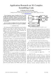
Block diagrams <strong>of</strong> the transmitter and receiver<br />
implementing the proposed <strong>PN</strong>-<strong>Scrambler</strong> are presented in<br />
Figs. 1 and 2, respectively.<br />
A/D Real<br />
A/D Imag<br />
Figure 1. <strong>PN</strong>-<strong>Scrambler</strong> Tx Block Diagram<br />
DC<br />
Offset<br />
DC<br />
Offset<br />
Subcarrier<br />
Demapper<br />
I / Q<br />
Imbalance<br />
I / Q<br />
Imbalance<br />
Channel<br />
Estimate<br />
Acquisition / Synchronization<br />
AGC<br />
Receive (Demodulation) Path<br />
Timing<br />
Detect<br />
Carrier<br />
Phase<br />
and<br />
Timing<br />
Drift<br />
Correction<br />
Coarse<br />
Freq<br />
S<strong>of</strong>t<br />
Bit<br />
Decisions<br />
Timing<br />
Fine<br />
Freq<br />
Deinterleaver<br />
and<br />
Convolutional<br />
decoder<br />
Sample<br />
Buffer<br />
Guard<br />
Interval<br />
Removal<br />
Descrambler<br />
FFT<br />
Data Bits<br />
Output<br />
Figure 2. <strong>PN</strong>-<strong>Scrambler</strong> Rx Block Diagram<br />
As seen in Fig. 1, two additional elements are added to<br />
a typical OFDM transmitter. The first element is the<br />
<strong>PAPR</strong> scrambler, and the second one is the <strong>PAPR</strong><br />
threshold compare block. The <strong>PN</strong>-<strong>Scrambler</strong> utilizes a<br />
Maximal-Length Linear Feedback Shift Register (ML-<br />
LFSR) with log2(k) = l taps in order to produce k = 2 l -1<br />
uncorrelated unique sets <strong>of</strong> data from the same input<br />
sequence. The k unique sets <strong>of</strong> data are used to generate k<br />
independent identically distributed (i.i.d.) OFDM symbols.<br />
A block <strong>of</strong> Nb bits comprising one OFDM symbol is<br />
2 <strong>of</strong> 7<br />
scrambled and passed along <strong>for</strong> Forward Error Correction<br />
(FEC) coding, interleaving, modulation, symbol mapping<br />
and IFFT.<br />
In any given OFDM system, Nb is a function <strong>of</strong> the<br />
number <strong>of</strong> subcarriers, the modulation scheme applied to<br />
each subcarrier, and the coding rate. By examining each<br />
individual sample coming out <strong>of</strong> the IFFT, the <strong>PAPR</strong><br />
threshold comparator determines if the scrambler has<br />
achieved a desired <strong>PAPR</strong> on a symbol-by-symbol basis. If<br />
the <strong>PAPR</strong> <strong>of</strong> the symbol is below a desired threshold, then<br />
the data is passed along towards the RF stage <strong>of</strong> the<br />
transmitter. However, if the <strong>PAPR</strong> is still high, the data is<br />
scrambled with a different phase <strong>of</strong> the ML-LFSR’s <strong>PN</strong><br />
sequence. Since this technique operates on the input bit<br />
stream, it is essentially independent <strong>of</strong> the OFDM<br />
modulation and may be adapted to any particular scenario.<br />
The receiver presented in Fig. 2 is a typical OFDM<br />
receiver that needs to per<strong>for</strong>m the tasks <strong>of</strong> down<br />
conversion, channel estimation, and decoding. The only<br />
additional task required by the <strong>PN</strong>-<strong>Scrambler</strong> <strong>PAPR</strong><br />
reduction technique is descrambling <strong>of</strong> the data at the<br />
receiver output. To per<strong>for</strong>m descrambling, the receiver<br />
has to “know” the phase <strong>of</strong> the ML-LFSR used on the<br />
transmission side. This phase is embedded in the data<br />
stream. For example, the first l bits <strong>of</strong> the OFDM symbol<br />
may carry the in<strong>for</strong>mation on the ML-LFSR phase.<br />
3.2. Analytical Per<strong>for</strong>mance Characterization<br />
A practical implementation <strong>of</strong> the <strong>PN</strong>-<strong>Scrambler</strong><br />
<strong>PAPR</strong> reduction technique requires selection <strong>of</strong> several<br />
parameters. These parameters are defined as follows.<br />
1. Number <strong>of</strong> scrambling sequences (k) - defined as the<br />
number <strong>of</strong> <strong>PN</strong> sequences produced by the ML-<br />
LFSR. Each sequence is Nb bits long.<br />
2. <strong>PAPR</strong> threshold (L) – defined as the maximum<br />
<strong>PAPR</strong> <strong>for</strong> the OFDM symbol. This value is used by<br />
the <strong>PAPR</strong> threshold comparator block in order to<br />
discard OFDM symbols with <strong>PAPR</strong> greater than L.<br />
3. IFFT size / number <strong>of</strong> sub-carriers (N) – defined as<br />
the number <strong>of</strong> the non-zero orthogonal subcarriers<br />
per OFDM symbol.<br />
4. Average latency ( k ) – defined as the average<br />
number <strong>of</strong> scrambling attempts per OFDM symbol<br />
in order to pass the threshold level L.<br />
5. Probability <strong>of</strong> clipping (p) – probability that the<br />
<strong>PAPR</strong> exceeds the threshold level L after k<br />
scrambling attempts.<br />
6. <strong>PN</strong> scrambler overhead ( v ) – defined as the ratio <strong>of</strong><br />
the number <strong>of</strong> bits required to represent the phase <strong>of</strong><br />
the ML-LFSR to the number <strong>of</strong> bits per OFDM<br />
symbol Nb.<br />
In any actual design, the above parameters allow different<br />
trade<strong>of</strong>fs. The subsequent section highlights some <strong>of</strong> these<br />
design trades.