Submersible Borehole Pumps 50 Hz - KSB
Submersible Borehole Pumps 50 Hz - KSB
Submersible Borehole Pumps 50 Hz - KSB
- TAGS
- submersible
- borehole
- pumps
- ksb.it

Create successful ePaper yourself
Turn your PDF publications into a flip-book with our unique Google optimized e-Paper software.
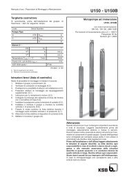
Type Series Booklet<br />
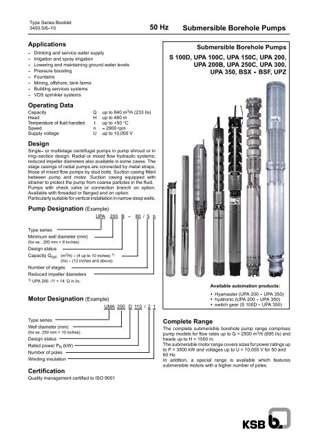
3400.5/6--10 <strong>50</strong> <strong>Hz</strong> <strong>Submersible</strong> <strong>Borehole</strong> <strong>Pumps</strong><br />
Applications<br />
-- Drinking and service water supply<br />
-- Irrigation and spray irrigation<br />
-- Lowering and maintaining ground water levels<br />
-- Pressure boosting<br />
-- Fountains<br />
-- Mining, offshore, tank farms<br />
-- Building services systems<br />
-- VDS sprinkler systems<br />
Operating Data<br />
Capacity Q up to 840 m 3 /h (233 l/s)<br />
Head H up to 480 m<br />
Temperature of fluid handled t up to +<strong>50</strong> °C<br />
Speed n ≈ 2900 rpm<br />
Supply voltage U up to 10,000 V<br />
Design<br />
Single-- or multistage centrifugal pumps in pump shroud or in<br />
ring--section design. Radial or mixed flow hydraulic systems;<br />
reduced impeller diameters also available in some cases. The<br />
stage casings of radial pumps are connected by metal straps,<br />
those of mixed flow pumps by stud bolts. Suction casing fitted<br />
between pump and motor. Suction casing equipped with<br />
strainer to protect the pump from coarse particles in the fluid.<br />
<strong>Pumps</strong> with check valve or connection branch on option.<br />
Available with threaded or flanged end on option.<br />
Particularly suitable for vertical installation in narrow deep wells.<br />
Pump Designation (Example)<br />
Type series<br />
Minimum well diameter (mm)<br />
(for ex.: 200 mm = 8 inches)<br />
Design status<br />
Capacity Qopt (m3 /h) -(4upto10inches) 1)<br />
(l/s) - (12 inches and above)<br />
Number of stages<br />
Reduced impeller diameters<br />
1) UPA 200 -11 + 14: Q in l/s.<br />
Motor Designation (Example)<br />
Type series<br />
Well diameter (mm)<br />
(for ex. 2<strong>50</strong> mm = 10 inches)<br />
Design status<br />
Rated power PN (kW)<br />
Number of poles<br />
Winding insulation<br />
Certification<br />
Quality management certified to ISO 9001<br />
UPA 200 B -- 80 / 5 b<br />
UMA 2<strong>50</strong> D 110 / 2 1<br />
<strong>Submersible</strong> <strong>Borehole</strong> <strong>Pumps</strong><br />
S 100D, UPA 100C, UPA 1<strong>50</strong>C, UPA 200,<br />
UPA 200B, UPA 2<strong>50</strong>C, UPA 300,<br />
UPA 3<strong>50</strong>, BSX - BSF, UPZ<br />
Available automation products:<br />
• Hyamaster (UPA 200 -- UPA 3<strong>50</strong>)<br />
• hyatronic (UPA 200 -- UPA 3<strong>50</strong>)<br />
• switch gear (S 100D -- UPA 3<strong>50</strong>)<br />
Complete Range<br />
The complete submersible borehole pump range comprises<br />
pump models for flow rates up to Q = 2<strong>50</strong>0 m 3 /h (695 l/s) and<br />
heads up to H = 1<strong>50</strong>0 m.<br />
The submersible motor range covers sizes for power ratings up<br />
to P = 3<strong>50</strong>0 kW and voltages up to U = 10,000 V for <strong>50</strong> and<br />
60 <strong>Hz</strong>.<br />
In addition, a special range is available which features<br />
submersible motors with a higher number of poles.
Contents Page<br />
The <strong>Submersible</strong> <strong>Borehole</strong> Pump Range ..................................... 4<br />
Operation with Soft Starters ................................................ 5<br />
Operation with Frequency Inverter ........................................... 6<br />
Typical Installation Positions ................................................ 7<br />
<strong>Submersible</strong> <strong>Borehole</strong> Pump Selection for Deep Wells ............................ 8<br />
Request for Quotation (Form) ............................................... 9<br />
Head Losses in the Piping ................................................. 10<br />
Pump Sets 4 inches ................................................. 11 + 23<br />
Pump Sets 6 inches ...................................................... 33<br />
Pump Sets 8 inches / 10 inches ............................................ 57<br />
Pump Sets 12 inches / 14 inches ........................................... 77<br />
Pump Sets 16 inches and above ...................................... 91 + 95<br />
Typical Tenders: 4 to 14 inches ............................................. 99<br />
<strong>Submersible</strong> Motors ..................................................... 104<br />
Accessories ............................................................ 106<br />
Flow Velocity “v” Past the Motor ...........................................<br />
116<br />
2<br />
<strong>50</strong> <strong>Hz</strong> <strong>Submersible</strong> <strong>Borehole</strong> <strong>Pumps</strong>
What can you expect from the<br />
“<strong>Submersible</strong> <strong>Borehole</strong> <strong>Pumps</strong> Booklet”?<br />
The information provided can help you make a<br />
-- quick<br />
-- first rough selection<br />
-- on your own<br />
to find a suitable <strong>KSB</strong> submersible borehole pump for your<br />
application. We have kept the volume of the catalogue down to<br />
what we think is the absolute minimum. For the 4 to 14 inch<br />
range, you will find the following information on the pump<br />
selected:<br />
-- pump series, size and number of stages,<br />
-- motor series, size, power, amperage, and allowable<br />
temperature,<br />
-- starting method, supply voltage and type of installation,<br />
-- material variants and<br />
-- major dimensions and weights.<br />
You may also complete, to the extent possible, the request for<br />
quotation on page 9.<br />
You will then receive as soon as possible a detailed quotation<br />
and, if required, additional literature on <strong>KSB</strong> submersible<br />
borehole pumps from the nearest <strong>KSB</strong> sales branch.<br />
Benefits at a Glance<br />
+ Full range of products<br />
+ High-tech equipment<br />
+ Optimum material selection<br />
+ Maximum efficiency<br />
+ Functional reliability<br />
+ Long service life<br />
+ No maintenance<br />
+ “Clean” technology<br />
+ Customer focus<br />
<strong>50</strong> <strong>Hz</strong><br />
General<br />
<strong>Submersible</strong> <strong>Borehole</strong> <strong>Pumps</strong><br />
Information on fields of application, available models, type of<br />
installation, direction of rotation, coating, connection to power<br />
supply and speed control is provided in the detailed sections for<br />
the relevant type series.<br />
The characteristic curves shown are for preliminary<br />
selection only. Exact selection data will be provided in our<br />
quotation.<br />
Pump Efficiency<br />
The characteristic curves for UPA 200/200B and larger pumps<br />
show pump efficiency for the maximum and optimum (reduced)<br />
impeller diameter (for ex. ”c”). The efficiency of pumps with a<br />
low number of stages or considerably reduced impeller<br />
diameter (for ex. ”d”, “e”) is lower than the value shown; it is<br />
given in the individual characteristic curves specifically<br />
prepared for the quotation.<br />
Dry Running Protection<br />
For use in wells with marked water level fluctuations or<br />
temporary low yield we strongly recommend installing dry<br />
running protection equipment (”Accessories”).<br />
Application Temperatures<br />
The submersible borehole pumps are, as a standard, suitable for<br />
use in water with temperatures of up to t = +30 o C. An<br />
indispensable requirement for this is a flow velocity of v = 0.2 m/s<br />
past the motor. This requirement is met, for example, when the<br />
pump is installed in a deep well above the well screen / filter, etc.<br />
With certain restrictions, some motor sizes may also be used<br />
in water with temperatures of up to t = +<strong>50</strong> o C and for operation<br />
without an adequate cooling flow of water past the motor, i.e.<br />
v = 0 m/s (for example, when the unit is installed in a deep well<br />
below the screen / filter area or in a pump sump, etc.).<br />
The details below provide data of adequate accuracy for the<br />
allowable temperature as a function of the type of installation,<br />
motor size and flow velocity v past the motor:<br />
Vertical installation:<br />
-- DN 100:<br />
tallow =t 1)<br />
max irrespective of flow past the motor.<br />
-- UMA 1<strong>50</strong>D/200D:<br />
v= 0m/s...... tallow ≈ t 1)<br />
max -- 5 oC, v ≥ 0.2 m/s ..... tallow = t 1)<br />
max ,<br />
v ≥ 0.5 m/s ..... tallow ≈ t 1)<br />
max +5oC. -- UMA 2<strong>50</strong>D:<br />
v = 0 m/s ...... Please consult manufacturer,<br />
v ≥ 0.2 m/s ..... tallow = t 1)<br />
max ,<br />
v ≥ 0.5 m/s tallow ≈ t 1)<br />
max ,+5oC. .....<br />
1) Values taken from tables on pages 15, 16 etc., 27, 28 etc..<br />
Horizontal installation:<br />
The principle is the same as for vertical installation.<br />
Exception: <strong>Pumps</strong> with UMA 2<strong>50</strong>D motors.<br />
These units must always be equipped with a flow inducer<br />
sleeve. The flow inducer sleeve is not required, if the given<br />
pump is equipped with a motor having a 10 % higher power<br />
rating.<br />
For all pump sets:<br />
For a flow velocity of v ≥ 0.5 m/s and horizontal installation, check<br />
back with the manufacturer.<br />
3
The <strong>Submersible</strong> <strong>Borehole</strong> Pump Range<br />
4<br />
" UPA 100C<br />
(4 inch)<br />
p. 23 -- 32<br />
" S 100D<br />
(4 inch)<br />
p. 11 -- 22<br />
" UPA 1<strong>50</strong>C<br />
(6 inch)<br />
p. 33 -- 56<br />
UPV 1<strong>50</strong>S<br />
(6 inch)<br />
on request<br />
UPA 200 "<br />
(8/10 inch)<br />
p. 57 -- 65<br />
<strong>50</strong> <strong>Hz</strong> <strong>Submersible</strong> <strong>Borehole</strong> <strong>Pumps</strong><br />
" UPV 200<br />
(8 inch)<br />
on request<br />
" UPZ<br />
BSX - BSF<br />
(≥ 16 inch)<br />
p. 91 -- 98<br />
on request<br />
" UPA 200B<br />
(8/10 inch)<br />
p. 65 -- 69<br />
" UPA 300, 3<strong>50</strong><br />
(12/14 inch)<br />
p. 77 -- 90<br />
" UPA 2<strong>50</strong>C<br />
(8/10 inch)<br />
p. 70 -- 76
Voltage [%]<br />
120<br />
100<br />
80<br />
60<br />
40<br />
20<br />
0<br />
Run--up Operation Run--down<br />
4s<br />
<strong>50</strong> <strong>Hz</strong><br />
Operation of <strong>KSB</strong> submersible motor pumps with soft starters<br />
Soft starter electronically reduce the incoming line voltage and,<br />
hence, the initial starting torque and starting current of electric<br />
motors. During run--up they gently ramp up the applied voltage<br />
to the motor.<br />
In the case of submersible motors, the extremely slim design<br />
and consequential small moments of inertia result in special<br />
characteristics, which differ strongly from normal<br />
asynchronous motors.<br />
Soft starter settings<br />
Time [s]<br />
<strong>Submersible</strong> <strong>Borehole</strong> <strong>Pumps</strong><br />
Effects on submersible borehole pumps<br />
-- Starting current ⇒ approx. 40% to 65% of IA required for<br />
direct-starting.<br />
-- Run-up time tH increased to approx. 1s to 3s compared<br />
with approx. 0.2s to 0.5s for direct. starting.<br />
-- Starting torque MA roughly 1/4 of the direct-starting<br />
torque.<br />
-- No current or torque peaks (IA,MA), as in star-delta<br />
switching arrangement.<br />
-- Hydraulic pressure surges (waterhammer) upon starting<br />
and stopping of the pump can be reduced, but not fully<br />
eliminated. Therefore, soft starters are not suitable for<br />
solving water hammer problems.<br />
This would require the use of hydraulic control equipment<br />
or a frequency inverter. To prevent effects due to power<br />
failure, additional measures are required.<br />
Note<br />
Conspicuous noise or vibrations during run-up could well be an<br />
indication of incorrect settings on the soft starter. This might be<br />
due to exceeded ramp--up periods, incorrect operating mode<br />
(setting), activated special functions, etc.<br />
Parameter / Function Setting Comments<br />
Minimum starting voltage 40% of the motors’ rated voltage<br />
Ramp time / acceleration < 4s Ramp time is nor identical with the motor<br />
(run--up) time<br />
actual run--up time<br />
Current limitation IA /IN preset to approx. 3.5 Should only be altered with allowance for<br />
tH < 4s<br />
Deceleration (run--down) time /<br />
stop ramp<br />
Deceleration time tA < 4s Better without a ramp.<br />
Special functions, e.g.:<br />
OFF Do not use, as they tend to be troublesome,<br />
-- special “pump function”<br />
particulary in submersible borehole applica-<br />
-- kick--start / boost function<br />
-- speed adjustment<br />
-- Current contoller<br />
-- cos ϕ- / economy function<br />
-- delayed starting<br />
tions.<br />
During operation the soft starter must be bridged (bypass). This helps to avoid losses at the machine and motor to secure proper<br />
permanent operation.<br />
4s<br />
5
Pump Operation with Frequency Inverter<br />
In principle, the motors of submersible borehole pumps can<br />
also be run on a frequency inverter. As submersible motors<br />
differ from conventional standardized motors in terms of<br />
bearings, moment of inertia, insulation, temperature increase,<br />
loss distribution and heat distribution, the following parameters<br />
must be observed:<br />
-- Maximum allowable acceleration time (start ramp)<br />
-- Maximum allowable deceleration time (stop ramp)<br />
-- Minimum frequency<br />
-- Maximum operating frequency<br />
-- Maximum permissible voltage increase velocity and peak<br />
voltages<br />
-- Control principle of frequency inverter<br />
Maximum Allowable Acceleration Time (Start<br />
Ramp) and Deceleration Time (Stop Ramp)<br />
The plain bearings of the submersible motor do not tolerate<br />
operation below the minimum frequency f min (operation in<br />
mixed lubrication range).<br />
For this reason, the acceleration period from standstill to<br />
minimum frequency f min should not exceed 2s. The same<br />
applies to the deceleration period.<br />
Minimum Frequency<br />
6<br />
Motor size<br />
Minimum frequency f min (<strong>Hz</strong>)<br />
Vertical<br />
installation<br />
Horizontal<br />
installation<br />
DN 100 30 30<br />
UMA 1<strong>50</strong>D 20 30<br />
UMA 200D<br />
UMA 2<strong>50</strong>D<br />
UMA 300D /2<br />
UMA 300D /4 30 35<br />
<strong>50</strong> <strong>Hz</strong> <strong>Submersible</strong> <strong>Borehole</strong> <strong>Pumps</strong><br />
Maximum Operating Frequency<br />
Frequency inverter operation above the nominal frequency<br />
(<strong>50</strong><strong>Hz</strong> / 60<strong>Hz</strong>) of the pump unit must be avoided so as to prevent<br />
motor overload.<br />
Maximum Permissible Voltage Increase Velocity<br />
and Peak Voltages<br />
Excessive voltage increase velocities and excessive peak<br />
voltages will reduce the service life of the winding insulation.<br />
For this reason, the following limits must be adhered to:<br />
-- Maximum voltage increase velocity:<br />
du/dt ≤ <strong>50</strong>0 V/µs<br />
-- Maximum peak voltages to earth:<br />
Low-voltage motors ≤ 1 kV: J1 insulation ≤ 600 V<br />
J2 insulation ≤ 800 V<br />
For motor sizes DN 100, the limit values for J1 insulation apply.<br />
Note: Compliance with these limits can usually be assured by<br />
means of a sine filter or du / dt filter.<br />
Control Principle of Frequency Inverter<br />
The control principle of the frequency inverter must correspond<br />
to linear U/f curve control. If other control principles are<br />
employed, such as field-oriented inverters, inverters with DTC<br />
or NOF, the manufacturer of the frequency inverter must ensure<br />
that the special requirements of submersible motors (very small<br />
moment of inertia, electrical data) are taken into account.<br />
Note: For details refer to ”Design and Selection Information for<br />
Running <strong>Submersible</strong> <strong>Borehole</strong> <strong>Pumps</strong> on Frequency<br />
Inverters”, Ref. No. 3400.0610--10.
Typical Installation Positions<br />
a) Vertical Installation<br />
(deep well, pump sump, etc.)<br />
CAUTION:<br />
The construction of the well head must meet the relevant<br />
regulations of the competent authorities! The unit must never<br />
be installed with its suction strainer exactly at the level of the<br />
well screen / filter!<br />
Before installing the unit in narrow deep wells we recommend to<br />
check narrow boreholes for dimensional accuracy over their<br />
entire length, e.g. by inserting a pipe of the length and biggest<br />
outside diameter of the pump unit. Sharp bends or bottlenecks<br />
can make installation difficult or even impossible.<br />
The unit is supported on the well head by supporting clamps<br />
(low-weight units and low submergence) or a supporting flange.<br />
The construction of the well head must meet the relevant<br />
regulations of the competent authority.<br />
1 <strong>Submersible</strong> borehole pump<br />
2 Riser pipe<br />
3 Cable tie<br />
4 Supporting flange / Well head<br />
5 Pressure gauge<br />
6 Shut-off valve<br />
7 Power supply cable<br />
8 Control box<br />
9 Well screen / filter<br />
6<br />
H t<br />
D<br />
TB =<br />
=<br />
Inside well diameter<br />
Well depth<br />
D<br />
TF = Well screen / filter depth<br />
He = Installation depth<br />
Hh = Static water level<br />
Ht = Dynamic water level (Pumping water level)<br />
Fig. 1 Vertical installation (in deep well, pump sump, etc.)<br />
4<br />
H h<br />
The suspension arrangement of the pump unit must be<br />
designed and dimensioned so that all static and dynamic forces<br />
can be absorbed and that the riser pipe cannot slip downwards.<br />
The supporting clamps or flanges must be fastened at the well<br />
head so that they cannot shift of lift off the well head.<br />
The unit must never be installed with its suction strainer exactly<br />
at the level of the well screen / filter! Excessive flow in the area<br />
of the well screen / filter entails the risk of large amounts of<br />
entrained sand clogging the well screen / filter and causing<br />
excessive wear in the pump.<br />
Pump units installed in a pump sump must generally be<br />
equipped with a cooling or suction shroud (fig. 2).<br />
3<br />
2<br />
1<br />
9<br />
5<br />
B<br />
B<br />
H e<br />
7<br />
T F<br />
8<br />
T B<br />
<strong>50</strong> <strong>Hz</strong><br />
Fig. 2 Installation in a pump sump<br />
<strong>Submersible</strong> <strong>Borehole</strong> <strong>Pumps</strong><br />
Cooling / Suction shroud<br />
b) Horizontal Installation<br />
(in reservoirs, mine shafts, etc.)<br />
CAUTION:<br />
The instructions given in ”a) Vertical installation” shall also apply<br />
by analogy to horizontal installation, when the pump unit is fitted<br />
on mounts (pedestals / supporting frame) supplied by us. If the<br />
pump and motor are supplied ready mounted on a supporting<br />
frame, on-site alignment of pump and motor will not be<br />
necessary. If this is not the case, the relevant installation /<br />
assembly drawing must be ordered, giving the following details:<br />
-- installation height (floor clearance),<br />
-- spacing of supports,<br />
-- submergence X<br />
The ground / foundation must be level and of sufficient<br />
load-bearing capacity to accept the weight of the unit with<br />
supports.<br />
Air intake from an inlet arranged above the water level is not<br />
permitted.<br />
X<br />
Fig. 3 Horizontal installation (in tanks, mine shafts etc.)<br />
1 <strong>Submersible</strong> borehole pump<br />
2 Water storage tanks (UMA 300D and 14D motors only)<br />
3 Pedestal<br />
4 Expansion joint<br />
5 Check valve<br />
(only if pump unit does not have its own check valve)<br />
6 Dismantling joint<br />
7 Shut-off valve<br />
8 Intake<br />
7
<strong>Submersible</strong> <strong>Borehole</strong> Pump Selection for Deep Wells<br />
Pump Selection<br />
The following data are required for a first rough selection of a<br />
submersible borehole pump:<br />
-- Capacity Q in m 3 /h (l/s)<br />
-- Pressure at well head H A in m<br />
-- Well diameter in inches or mm<br />
-- Temperature of fluid handled t A in °C<br />
-- Pump head H P in m<br />
While Q, H A, D and t A are usually specified by the customer, the<br />
head H P to be developed by the pump needs to be calculated.<br />
There are two typical applications to be considered (see the<br />
drawing on the right):<br />
1. Pumping into an open overhead tank<br />
HP =HA + Ht +Hv +HS [m]<br />
where ...<br />
HA = Required pressure at well head<br />
Ht = Lowest water level (dynamic water level)<br />
Hv = Head losses in the check valve (see characteristic<br />
curves for different stage numbers for UPA 1<strong>50</strong>C<br />
and above).<br />
HS = Head losses in riser pipe up to well head<br />
(see page 10).<br />
He = Installation depth<br />
2. Pumping into a closed tank<br />
Hp =HA +Ht +Hv +HS +pü [m]<br />
where ...<br />
pü = Gauge pressure (also air cushion) in a tank<br />
Example<br />
Given ...<br />
QA = 120 m3 /h,<br />
HA = 95 m,<br />
tA = + 15 °C,<br />
<strong>50</strong> <strong>Hz</strong>, 400 V and d.o.l. starting,<br />
well diameter D = 2<strong>50</strong> mm (10 inches).<br />
Found ...<br />
1. step:<br />
pump type UPA 200B/2<strong>50</strong>C<br />
(for QA taken from selection chart on page 4)<br />
2. step:<br />
pump size UPA 200B - 130<br />
(for QA taken from selection chart on page <strong>50</strong>)<br />
3. step:<br />
pump set UPA 200B-130/6b + UMA 200D 45/21<br />
(for Hp =HA +Ht +HV +HS = 95 + 4 + 0.75 + 0.26 = 100 m<br />
with HV taken from characteristic curves for different stage<br />
numbers on page 61).<br />
Pump efficiency: ηP = 80.5 % (without check valve)<br />
8<br />
<strong>50</strong> <strong>Hz</strong> <strong>Submersible</strong> <strong>Borehole</strong> <strong>Pumps</strong><br />
3300:54/3<br />
Figure:<br />
Deep well with submersible borehole pump and overhead tank<br />
or closed tank at a pressure above atmospheric pressure of p ü.
F<br />
6<br />
7<br />
3300:54/3<br />
1 Well screen / filter<br />
2 Well casing<br />
3 <strong>Submersible</strong> borehole pump<br />
4 Riser<br />
5 Well head housing<br />
6 Well head<br />
7 Power supply cable<br />
8 Overhead tank<br />
8<br />
4<br />
3<br />
2<br />
1<br />
5<br />
<strong>50</strong> <strong>Hz</strong> <strong>Submersible</strong> <strong>Borehole</strong> <strong>Pumps</strong><br />
Request for Quotation<br />
We should like to test the efficiency and quality of your computer-aided quotation process.<br />
Please let us have a quotation based on the following data. (Fill in the required data and<br />
/ or underline the relevant information, as far as available.)<br />
1. Water quality<br />
Temperature ..................... °C<br />
Sand content g/m3 ..................<br />
Please attach water analysis, if available.<br />
2. Type of system<br />
Well / Mine shaft / Tank<br />
Free discharge above ground<br />
Discharge into an overhead tank<br />
Discharge into a pressure vessel<br />
3. Deep well<br />
Well depth (distance from ground level to<br />
well base):<br />
TB = ............................ m<br />
Inside diameter at submersible pump<br />
installation depth:<br />
D = .............. mm ( .... inches)<br />
Well screen / filter:<br />
-- Installation depth TF = ........... m<br />
-- Length LF = ................... m<br />
4. Capacity<br />
Q= m3 ............. /h ( ....... l/s)<br />
5. Total head<br />
(including all friction losses)<br />
H= ............................ m<br />
If H is not known, please provide the<br />
following data:<br />
a)<br />
Water level in well, measured from<br />
ground level:<br />
-- Static water level: Hh = .......... m<br />
-- Dynamic water level: Ht = ........ m<br />
(at capacity Q = m3 .............. /h)<br />
b)<br />
Head above ground:<br />
Geodetic altitude up to the highest point<br />
of the pipeline or up to the highest water<br />
level in the overhead tank:<br />
Hd = ........................... m<br />
Discharge head required at the end of the<br />
piping:<br />
H = ............. m ( ........ bar)<br />
Cut-out pressure in the pressure vessel:<br />
pÜ = ............ bar<br />
c)Piping outside well head housing:<br />
Overall length .................... m<br />
Nominal diameter ............... mm<br />
Number of bends, valves and fittings:<br />
................................ pcs<br />
Inside diameter reduced by incrustation<br />
to: D = ........................ mm<br />
6. Installation depth<br />
Ground level to check valve / to<br />
connection branch:<br />
He = ............ m<br />
Caution: Do not install the submersible<br />
borehole pump at the level of the well<br />
screen / filter!<br />
7. Power supply<br />
Single- / three-phase alternating current.<br />
Mains voltage at well:<br />
U= ............................. V<br />
Frequency f = .................. <strong>Hz</strong><br />
If voltage drops cannot be precluded:<br />
Minimum voltage ...<br />
Umin = ........... V<br />
8. Control box<br />
Manual start-up / remote control / automatic<br />
start-up by way of float switch,<br />
pressure switch or dry running protection<br />
equipment.<br />
Other types of switchgear: ...........<br />
...................................<br />
9. Starting method<br />
D.o.l. (without / with autotransformer or<br />
soft starter) or star-delta starting.<br />
9
Head losses in the piping<br />
H V<br />
m/100 m<br />
The friction losses given in the above chart roughly apply to new<br />
cast iron pipes. For new rolled steel or plastic pipes, multiply the<br />
values by approx. 0.8. For old, slightly rusty cast iron pipes,<br />
multiply by approx. 1.25. In pipes with incrustations, friction<br />
losses may rise to 1.7 times the value given in the chart for the<br />
10<br />
<strong>50</strong> <strong>Hz</strong> <strong>Submersible</strong> <strong>Borehole</strong> <strong>Pumps</strong><br />
H V<br />
ft/100 ft<br />
3300:103/3-2<br />
diameter reduced by incrustations. For pipes subject to considerable<br />
incrustation, the friction losses can only be determined<br />
experimentally.<br />
Example: Q = 140 m 3 /h, new DN 1<strong>50</strong> cast iron pipe.<br />
H V = 3.25 m per 100 m of pipe, v = 2.2 m/sec.
Applications<br />
-- Domestic and general water supply<br />
-- Irrigation and spray irrigation<br />
-- Lowering groundwater levels<br />
-- Fountains<br />
-- Pressure boosting<br />
-- Air-conditioning systems<br />
-- Fire protection<br />
-- Cooling water cycles<br />
Operating Data<br />
Capacity Q up to 16 m 3 /h (4.4 l/s)<br />
Head H up to 300 m<br />
Temperature of fluid handled t up to +30 °C<br />
in continuous operation<br />
Power Pn up to 5.5 kW<br />
Pump Type / Design<br />
Pump:<br />
Stainless steel and plastic multistage centrifugal pump.<br />
-- Additional bearing depending on the number of stages<br />
-- Pump sizes D1 and D2 with anti-blockage feature. This consists<br />
of a hexagonal polyurethane disc mounted to the back<br />
of the diffuser. A PE-HD ring fitted to the impeller front side<br />
sits close to the disc. The impeller hub is protected by a polyurethane<br />
ring.This design improves the starting torque of lowcapacity<br />
pumps and has the effect that solid particles such as<br />
sand are propelled outside instead of clogging the pump.<br />
Motor:<br />
<strong>Submersible</strong> canned motor (Franklin), NEMA standard, <strong>50</strong> <strong>Hz</strong><br />
-- For single-phase alternating current (type PSC) or threephase<br />
current<br />
-- With short cable<br />
-- Connection to power supply mains by means of cable connector<br />
(accessories)<br />
-- D.o.l. starting, start-up frequency up to 20/h<br />
-- Type of enclosure IP 68<br />
-- Thermal class B<br />
Designation<br />
Type series<br />
Well diameter (mm)<br />
Status<br />
Capacity (m 3 /h)<br />
Number of stages<br />
S 100 D -- 4 / 6<br />
Recommended Accessories<br />
UPA Control: Control box for motor and dry running protection<br />
by immersion electrodes.<br />
Automatic control unit: in conjunction with the Controlmatic<br />
E or Cervomatic EDP control and monitoring units, which protect<br />
the pump against dry running, if the water level falls, S 100D<br />
can be used for automatic water supply<br />
Certification<br />
Quality management certified to ISO 9001<br />
<strong>50</strong> <strong>Hz</strong> S 100D<br />
<strong>Submersible</strong> <strong>Borehole</strong> <strong>Pumps</strong><br />
for Well Diameters<br />
of 100 mm (4 inch)<br />
Available automation products:<br />
• Automatic control unit<br />
Product Features<br />
-- <strong>Pumps</strong> sizes D1 and D2 with anti-blockage feature<br />
-- Rust-proof<br />
-- Suitable for installation in narrow deep wells<br />
-- High efficiency<br />
-- Hermetically sealed motor<br />
-- Motor designed for maximum pump output<br />
-- Low noise level<br />
-- For vertical, angled or horizontal installation<br />
11
12<br />
<strong>50</strong> <strong>Hz</strong> S 100D<br />
Selection Chart (Ranges on Offer) n ≈ 2900 rpm<br />
Note:<br />
Up to a motor rating of P N = 2.2 kW, all pump sizes can be supplied with either single-phase a.c. or three-phase current motors.
Materials<br />
Component C1<br />
Pump ...<br />
Outer pump casing/<br />
CrNi steel (1.4301)<br />
Suction casing /<br />
Valve housing<br />
Stage casing CrNi steel (1.4301)<br />
Stage casing (diffuser) /<br />
Impeller<br />
glass fibre reinforced Noryl<br />
(PPO GF20V)<br />
Shaft Cr-steel (1.4021)<br />
Bearing bush Nitril NBR 80<br />
Screws, bolts and nuts<br />
Motor ...<br />
CrNiMo-steel (A4--70)<br />
Shaft CrNi steel (1.4305)<br />
Bearing carrier CrNi steel (1.4301)<br />
Stator case CrNi steel (1.4301)<br />
Bearings / Lubrication<br />
Plain bearings, lubricated by the fluid pumped or by the motor<br />
fill liquid. Depending on the number of stages, an additional intermediate<br />
bearing is provided in the pump.<br />
The axial thrust is balanced by a thrust bearing in the motor.<br />
The hydraulic thrust is balanced by the pump’s counter thrust<br />
bearing.<br />
Direction of Rotation of the Pump<br />
Clockwise rotation (viewed at the drive shaft end).<br />
Pump End (Discharge Nozzle)<br />
S 100D - 1, 2, 4 + 7: Internal thread G 1 1 / 4” (DN 32).<br />
S 100D - 12: Internal thread G 2” (DN <strong>50</strong>).<br />
Installation<br />
Vertical and, depending on the number of stages, also angled<br />
and horizontal installation.<br />
<strong>50</strong> <strong>Hz</strong> S 100D<br />
Drive<br />
Type .................... canned motor in squirrelcage<br />
design, 2 poles<br />
Connection .............. NEMA standard<br />
Type of enclosure ........ IP 68<br />
Frequency .............. <strong>50</strong> <strong>Hz</strong><br />
Type of current ........... single-phase a.c. (1 µ)<br />
or three-phase (3 µ)<br />
Rated voltage U .......... 220 ... 230 V (1~) and<br />
380 ... 400 V (3~)<br />
Rated power PN ............ up to 2.2 kW for 1~ and<br />
up to 5.5 kW for 3~<br />
Voltage fluctuation ........ up to ± 5 % acc. to VDE<br />
Frequency of starts ....... up to 20/h<br />
Min. delay before restarting . 3 min<br />
A starter for single-phase a.c. motors in PSC design (with<br />
integrated run capacitor and motor protection) is included in the<br />
scope of supply.<br />
Connection to Power Supply<br />
All DN 100 motors are factory-equipped as follows:<br />
1 x 1.5 m flat cable, quality 4 x 1.5 mm 2 (3 phases + 1 earth conductor).<br />
Exception: DN 100 motors with a rating of 5.5 kW, 3~, are<br />
equipped as follows: 2.5 m cable, quality 4 x 1.5 mm 2 .<br />
Connection of extension cable (any length) by means of a cable<br />
connector<br />
Connected at the factory by means of a standard cable connector<br />
(non-separable, shrink tube)<br />
Ident. No. 40 980 708<br />
For cable quality 4 x 1.5 mm 2 or 4 x 2.5 mm 2<br />
Ident. No. 39 020 536<br />
For cable quality 4 x 4 mm 2<br />
Connected at the factory with Franklin cable connector<br />
(separable, sealing compound)<br />
Ident. No. 90 049 385<br />
For cable quality 4 x 1.5 mm 2 up to 4 x 2.5 mm 2<br />
Starting Mode<br />
Only direct on line.<br />
Temperatures<br />
The S 100D submersible borehole pump is designed for use in<br />
water with temperatures of up to t = + 30 o C.<br />
Variants Available on Request<br />
-- Higher fluid temperatures<br />
-- Higher voltages up to <strong>50</strong>0 V<br />
-- Other frequencies<br />
13
Design Features (Pump sizes D1 -- D2)<br />
Easy to commission and service<br />
D Vent valve for operation with automatic<br />
control units such as Controlmatic E or<br />
Cervomatic EDP<br />
D Easy to install thanks to plug--type<br />
connection of power cable of Franklin<br />
submersible motor<br />
D The cable guard is easy to fit and remove.<br />
14<br />
High-duty impellers<br />
D Made of glass fibre-reinforced Noryl,<br />
highly abrasion- and<br />
corrosion-resistant.<br />
D With integrated keys for<br />
easy assembly.<br />
Highly corrosion -resistant<br />
D Suction casing, check valve<br />
housing and outer casing made of<br />
stainless steel<br />
D Hydraulic system made of glass<br />
fibre reinforced Noryl<br />
<strong>50</strong> <strong>Hz</strong> S 100D<br />
High operating reliability and<br />
long service life<br />
D Maintenance--free and wear--protected<br />
pump bearings<br />
D Special guide feature prevents jamming<br />
or tilting of the check valve<br />
D Cable guard protects cables from damage.<br />
Stainless steel cable guard<br />
D Easy assembly and dismantling.<br />
D Protects the power supply cable against<br />
damage during installation and<br />
dismantling.<br />
Stainless steel stage casing<br />
without return vanes<br />
D High pressure resistance.<br />
D Easy assembly and dismantling.
S 100D - 1 ...<br />
for well diameters of 100 mm (4 inch)<br />
<strong>Pumps</strong> with submersible motors for ...<br />
-- Temperature of fluid handled up to + 30 o ............<br />
C<br />
-- Current / Operating voltage .................. 1~/230 V<br />
....................................... or 3~/400 V<br />
-- Starting ...................................... direct<br />
Pump unit<br />
S 100D<br />
Rated<br />
power<br />
(motor)<br />
P N<br />
kW<br />
Current intensity for<br />
...<br />
1~<br />
230 V<br />
I N 1)<br />
A<br />
3~<br />
400 V<br />
I N<br />
A<br />
For information on cooling shroud refer to page 20.<br />
Installation<br />
2)<br />
Operation<br />
with<br />
control<br />
unit<br />
3 )<br />
1/ 7 0.37 3.4 1.3 v+h x<br />
1/ 9 0.37 3.4 1.3 v+h x<br />
1/12 0.55 3.4 1.3 v+h x<br />
1/14 0.55 4.3 1.7 v+h x<br />
1/16 0.55 4.3 1.7 v+h x 3)<br />
1/20 0.75 4.3 1.7 v+h x 3)<br />
1/25 1.10 5.7 2.2 v x 3)<br />
1/30 1.10 5.7 2.2 v x 3)<br />
1/35 1.<strong>50</strong> 8.6 3.2 v x 3)<br />
1/40 1.<strong>50</strong> 8.6 3.2 v x 3)<br />
1/<strong>50</strong> 2.20 10.6 4.0 v x 3)4)<br />
1) Capacitor run motors (PSC motors) with starter.<br />
2) v = vertical and h = inclined / horizontal.<br />
3) Always check and make sure that the operating pressure of Controlmatic /<br />
Cervomatic units is not exceeded.<br />
4) 3~ only<br />
Note : Use a cooling shroud for horizontal installation.<br />
Dimensions / Weights / Ident. Numbers / Horizontal Installation<br />
Pump unit<br />
S 100D<br />
1/ 7<br />
1/ 9<br />
1/ 12<br />
1/ 14<br />
1/ 16<br />
1/ 20<br />
1/ 25<br />
1/ 30<br />
1/ 35<br />
1/ 40<br />
1/ <strong>50</strong><br />
L A<br />
≈ mm<br />
575<br />
625<br />
720<br />
795<br />
810<br />
925<br />
1100<br />
1210<br />
1395<br />
1<strong>50</strong>5<br />
1805<br />
m A<br />
≈ kg<br />
11.5<br />
11.7<br />
13.4<br />
13.6<br />
13.8<br />
14.3<br />
16.3<br />
16.8<br />
20.0<br />
20.6<br />
22.7<br />
1~/ 230 V 3~/ 400 V<br />
Ident No. A<br />
≈ mm<br />
39 022 528<br />
39 022 529<br />
39 022 530<br />
39 022 531<br />
39 022 532<br />
39 022 533<br />
39 022 534<br />
39 022 535<br />
39 022 536<br />
39 022 537<br />
39 022 538<br />
371<br />
425<br />
<strong>50</strong>8<br />
552<br />
597<br />
687<br />
-- -- -- --<br />
- - - -<br />
-- -- -- --<br />
- - - -<br />
-- -- -- --<br />
<strong>50</strong> <strong>Hz</strong> S 100D<br />
L A<br />
≈ mm<br />
555<br />
605<br />
700<br />
755<br />
780<br />
870<br />
1045<br />
11<strong>50</strong><br />
1310<br />
14<strong>50</strong><br />
1705<br />
Tolerances to<br />
ISO 9906 Class 2<br />
Annex A<br />
Capacity<br />
The characteristic curves shown are for preliminary selection only.<br />
Exact selection data will be provided in our quotation.<br />
m A<br />
≈ kg<br />
10.7<br />
10.9<br />
12.2<br />
12.4<br />
12.6<br />
13.1<br />
14.9<br />
15.4<br />
17.4<br />
18.0<br />
20.3<br />
Ident No. A<br />
≈ mm<br />
39 022 565<br />
39 022 566<br />
39 022 567<br />
39 022 568<br />
39 022 569<br />
39 022 570<br />
39 022 571<br />
39 022 572<br />
39 022 573<br />
39 022 574<br />
39 022 575<br />
362<br />
416<br />
492<br />
537<br />
582<br />
672<br />
-- -- -- --<br />
- - - -<br />
-- -- -- --<br />
- - - -<br />
-- -- -- --<br />
Accessories: UPA Control for dry running protection using 1 or 3 immersion electrodes, see page 21.<br />
C<br />
G1 1 / 4”<br />
15
S 100D - 2 ...<br />
for well diameters of 100 mm (4 inch)<br />
<strong>Pumps</strong> with submersible motors for ...<br />
-- Temperature of fluid handled up to + 30 o ............<br />
C<br />
-- Current / Operation voltage .................. 1~/230 V<br />
...................................... or. 3~/400 V<br />
-- Starting ...................................... direct<br />
Rated Current intensity InstalOpera- power p<br />
( (motor) t )<br />
for ...<br />
1~ 3~<br />
230 V 400 V<br />
lation<br />
2)<br />
tion with<br />
control t l<br />
unit<br />
3 )<br />
Pump unit<br />
S 100D<br />
PN kW<br />
I 1)<br />
N<br />
A<br />
IN A<br />
2/ 7 0.37 3.4 1.3 v+h x<br />
2/11 0.55 4.3 1.7 v+h x<br />
2/15 0.75 5.6 2.2 v+h x<br />
2/18 1.1 8.6 3.2 v+h x 3)<br />
2/20 1.1 8.6 3.2 v+h x 3)<br />
2/22 1.1 8.6 3.2 v+h x 3)<br />
2/27 1.5 10.6 4.0 v+h x 3)<br />
2/30 1.5 10.6 4.0 v x 3)<br />
2/33 2.2 15.5 5.9 v x 3)<br />
2/38 2.2 15.5 5.9 v x 3)<br />
2/44 2.2 15.5 5.9 v x 3)<br />
2/<strong>50</strong> 3.0 -- 7.8 v x 3)4)<br />
1) Capacitor run motors (PSC motors) with starter.<br />
2) v = vertical and h = inclined / horizontal.<br />
3) Always check and make sure that the operating pressure of Controlmatic /<br />
Cervomatic units is not exceeded.<br />
4) 3~ only<br />
Note : Use a cooling shroud for horizontal installation.<br />
Dimensions / Weights / Ident. Numbers / Horizontal Installation<br />
Pump unit<br />
S 100D<br />
2/ 7<br />
2/11<br />
2/15<br />
2/18<br />
2/20<br />
2/22<br />
2/27<br />
2/30<br />
2/33<br />
2/38<br />
2/44<br />
2/<strong>50</strong><br />
For information on cooling shroud refer to page 20.<br />
16<br />
LA ≈ mm<br />
570<br />
695<br />
815<br />
940<br />
985<br />
1030<br />
1175<br />
1235<br />
1425<br />
1535<br />
1670<br />
- - - - -<br />
mA ≈ kg<br />
11.3<br />
13.0<br />
14.8<br />
17.7<br />
17.8<br />
18.0<br />
19.5<br />
19.9<br />
23.6<br />
24.1<br />
24.6<br />
- - - - -<br />
1~/ 230 V 3~/ 400 V<br />
Ident No. A<br />
≈ mm<br />
39 022 539<br />
39 022 540<br />
39 022 541<br />
39 022 542<br />
39 022 543<br />
39 022 544<br />
39 022 545<br />
39 022 546<br />
39 022 547<br />
39 022 548<br />
39 022 549<br />
- - - - -<br />
371<br />
484<br />
589<br />
684<br />
729<br />
775<br />
901<br />
- - - -<br />
-- -- -- --<br />
- - - -<br />
-- -- -- --<br />
- - - -<br />
<strong>50</strong> <strong>Hz</strong> S 100D<br />
LA ≈ mm<br />
5<strong>50</strong><br />
665<br />
790<br />
880<br />
925<br />
970<br />
1120<br />
1180<br />
1325<br />
1435<br />
1570<br />
1770<br />
Tolerances to<br />
ISO 9906 Class 2<br />
Annex A<br />
Capacity<br />
The characteristic curves shown are for preliminary selection only.<br />
Exact selection data will be provided in our quotation.<br />
mA ≈ kg<br />
10.5<br />
11.8<br />
13.4<br />
15.1<br />
15.2<br />
15.4<br />
17.1<br />
17.5<br />
19.0<br />
19.5<br />
20.0<br />
23.6<br />
Ident No. A<br />
≈ mm<br />
39 022 576<br />
39 022 577<br />
39 022 578<br />
39 022 579<br />
39 022 580<br />
39 022 581<br />
39 022 582<br />
39 022 583<br />
39 022 584<br />
39 022 585<br />
39 022 586<br />
39 022 587<br />
362<br />
470<br />
574<br />
655<br />
701<br />
746<br />
873<br />
- - - -<br />
-- -- -- --<br />
- - - -<br />
-- -- -- --<br />
- - - -<br />
Accessories: UPA Control for dry running protection using 1 or 3 immersion electrodes, see page 21.<br />
C<br />
G1 1 / 4”
S 100D - 4 ...<br />
for well diameters of 100 mm (4 inch)<br />
<strong>Pumps</strong> with submersible motors for ...<br />
-- Temperature of fluid handled up to + 30 o ............<br />
C<br />
-- Current / Operating voltage .................. 1~/230 V<br />
...................................... or 3~/400 V<br />
-- Starting ...................................... direct<br />
Pump unit<br />
S 100D<br />
Rated<br />
power p<br />
( (motor) t )<br />
P N<br />
kW<br />
Current intensity<br />
for ...<br />
1~<br />
230 V<br />
I N 1)<br />
A<br />
3~<br />
400 V<br />
For information on cooling shroud refer to page 20.<br />
InstalOperalationtion with<br />
2) control t l<br />
unit<br />
3)<br />
4/ 3 0.37 3.4 1.3 v+h x<br />
4/ 6 0.55 4.3 1.7 v+h x<br />
4/ 8 0.75 5.7 2.2 v+h x<br />
4/11 1.10 8.6 3.2 v+h x<br />
4/16 1.<strong>50</strong> 10.6 4.0 v+h x 3)4)<br />
4/21 2.20 15.5 5.9 v+h x 3)4)<br />
4/24 2.20 15.5 5.9 v x 3)4)<br />
4/33 3.00 -- -- -- 7.8 v x 3)4)<br />
4/40 3.70 -- -- -- 9.1 v x 3)4)<br />
1) Capacitor run motors (PSC motors) with starter.<br />
2) v = vertical and h = inclined / horizontal.<br />
3) Always check and make sure that the operating pressure of Controlmatic /<br />
Cervomatic units is not exceeded.<br />
4) 3~ only<br />
Note : Use a cooling shroud for horizontal installation.<br />
I N<br />
A<br />
Dimensions / Weights / Ident. Numbers / Horizontal Installation<br />
Pump unit<br />
S 100D<br />
4/ 3<br />
4/ 6<br />
4/ 8<br />
4/11<br />
4/16<br />
4/21<br />
4/24<br />
4/33<br />
4/40<br />
L A<br />
≈ mm<br />
<strong>50</strong>5<br />
610<br />
690<br />
820<br />
975<br />
1180<br />
1255<br />
- - - -<br />
-- -- -- --<br />
m A<br />
≈ kg<br />
11.5<br />
13.4<br />
15.1<br />
18.2<br />
20.1<br />
24.8<br />
25.3<br />
- - - -<br />
-- -- -- --<br />
1~ / 230 V 3~ / 400 V<br />
Ident No. A<br />
≈ mm<br />
39 022 5<strong>50</strong><br />
39 022 551<br />
39 022 552<br />
39 022 553<br />
39 022 554<br />
39 022 555<br />
39 022 556<br />
- - - - -<br />
-- -- -- -- --<br />
333<br />
399<br />
489<br />
594<br />
734<br />
900<br />
-- -- -- --<br />
- - - -<br />
-- -- -- --<br />
<strong>50</strong> <strong>Hz</strong> S 100D<br />
L A<br />
≈ mm<br />
485<br />
580<br />
665<br />
760<br />
920<br />
1080<br />
1155<br />
1595<br />
1805<br />
Tolerances to<br />
ISO 9906 Class 2<br />
Annex A<br />
Capacity<br />
The characteristic curves shown are for preliminary selection only.<br />
Exact selection data will be provided in our quotation.<br />
m A<br />
≈ kg<br />
10.7<br />
12.2<br />
13.7<br />
15.6<br />
17.7<br />
20.2<br />
20.7<br />
25.5<br />
33.0<br />
Ident No. A<br />
≈ mm<br />
39 022 588<br />
39 022 589<br />
39 022 590<br />
39 022 591<br />
39 022 592<br />
39 022 593<br />
39 022 594<br />
39 022 595<br />
39 022 596<br />
324<br />
384<br />
475<br />
566<br />
706<br />
847<br />
-- -- -- --<br />
- - - -<br />
-- -- -- --<br />
Accessories: UPA Control for dry running protection using 1 or 3 immersion electrodes, see page 21.<br />
C<br />
G1 1 / 4”<br />
17
S 100D - 7 ...<br />
for well diameters of 100 mm (4 inch)<br />
<strong>Pumps</strong> with submersible motors for ...<br />
-- Temperature of fluid handled up to + 30 o ............<br />
C<br />
-- Current / Operating voltage .................. 1~/230 V<br />
....................................... or 3~/400 V<br />
-- Starting ...................................... direct<br />
Pump unit<br />
S 100D<br />
Rated<br />
power p<br />
( (motor) t )<br />
P N<br />
kW<br />
Current intensity<br />
for ...<br />
1~<br />
230 V<br />
I N 1)<br />
A<br />
3~<br />
400 V<br />
For information on cooling shroud refer to page 20.<br />
InstalOperalationtion with<br />
2) control t l<br />
unit<br />
3)<br />
7/ 4 0.75 5.7 2.2 v+h x<br />
7/ 6 1.10 8.6 3.2 v+h x<br />
7/ 8 1.<strong>50</strong> 10.6 4.0 v+h x 4)<br />
7/11 2.20 15.5 5.9 v+h x 4)<br />
7/13 2.20 15.5 5.9 v+h x 4)<br />
7/18 3.00 -- -- -- 7.8 v+h x 3)4)<br />
7/23 3.70 -- -- -- 9.1 v x 3)4)<br />
7/28 5.<strong>50</strong> -- -- -- 13.7 v x 3)4)<br />
7/33 5.<strong>50</strong> -- -- -- 13.7 v x 3)4)<br />
1) Capacitor run motors (PSC motors) with starter.<br />
2) v = vertical and h = inclined / horizontal.<br />
3) Always check and make sure that the operating pressure of Controlmatic /<br />
Cervomatic units is not exceeded.<br />
4) 3~ only<br />
Note : Use a cooling shroud for horizontal installation.<br />
I N<br />
A<br />
Dimensions / Weights / Ident. Numbers / Horizontal Installation<br />
Pump unit<br />
S 100D<br />
7/ 4<br />
7/ 6<br />
7/ 8<br />
7/11<br />
7/13<br />
7/18<br />
7/23<br />
7/28<br />
7/33<br />
L A<br />
≈ mm<br />
611<br />
736<br />
831<br />
1011<br />
1076<br />
- - - -<br />
-- -- -- --<br />
- - - -<br />
-- -- -- --<br />
m A<br />
≈ kg<br />
14.6<br />
17.7<br />
19.1<br />
23.1<br />
23.6<br />
- - - -<br />
-- -- -- --<br />
- - - -<br />
-- -- -- --<br />
1~ / 230 V 3~ / 400 V<br />
Ident No. A<br />
≈ mm<br />
39 022 557<br />
39 022 558<br />
39 022 559<br />
39 022 560<br />
39 022 561<br />
- - - - -<br />
-- -- -- -- --<br />
- - - - -<br />
-- -- -- -- --<br />
421<br />
517<br />
599<br />
740<br />
808<br />
- - - -<br />
-- -- -- --<br />
- - - -<br />
-- -- -- --<br />
<strong>50</strong> <strong>Hz</strong> S 100D<br />
L A<br />
≈ mm<br />
586<br />
676<br />
776<br />
911<br />
976<br />
1211<br />
1516<br />
1881<br />
2051<br />
Tolerances to<br />
ISO 9906 Class 2<br />
Annex A<br />
The characteristic curves shown are for preliminary selection only.<br />
Exact selection data will be provided in our quotation.<br />
Accessories: UPA Control for dry running protection using 1 or 3 immersion electrodes, see page 21.<br />
18<br />
m A<br />
≈ kg<br />
13.2<br />
15.1<br />
16.7<br />
18.5<br />
19.0<br />
23.1<br />
30.8<br />
38.3<br />
39.4<br />
Ident No. A<br />
≈ mm<br />
39 022 597<br />
39 022 598<br />
39 022 599<br />
39 022 600<br />
39 022 601<br />
39 022 602<br />
39 022 603<br />
39 022 604<br />
39 022 605<br />
407<br />
489<br />
571<br />
687<br />
755<br />
958<br />
-- -- -- --<br />
- - - -<br />
-- -- -- --<br />
C<br />
G1 1 / 4”<br />
Capacity
S 100D - 12 ...<br />
for well diameters for 100 mm (4 inch)<br />
<strong>Pumps</strong> with submersible motors for ...<br />
-- Temperature of fluid handled up to + 30 o ............<br />
C<br />
-- Current / Operation voltage .................. 1~/230 V<br />
....................................... or 3~/400 V<br />
-- Starting ...................................... direct<br />
Pump unit<br />
S 100D<br />
Rated<br />
power p<br />
( (motor) t )<br />
P N<br />
kW<br />
Current intensity<br />
for ...<br />
1~ 3~<br />
230 V 400 V<br />
I N 1)<br />
A<br />
For information on cooling shroud refer to page 20.<br />
Installation<br />
2)<br />
Operation<br />
with<br />
control t l<br />
unit<br />
3)<br />
12 / 4 1.1 8.6 3.2 v+h x<br />
12 / 6 1.5 10.6 4.0 v+h x<br />
12 / 10 2.2 15.5 5.9 v+h x<br />
12 / 13 3.0 -- -- -- 7.8 v x 4)<br />
12 / 17 3.7 -- -- -- 9.1 v x 3)4)<br />
12 / 21 5.5 -- -- -- 13.7 v -- -- --<br />
12 / 25 5.5 -- -- -- 13.7 v -- -- --<br />
1) Capacitor run motors (PSC motors) with starter.<br />
2) v = vertical and h = inclined / horizontal.<br />
3) Always check and make sure that the operating pressure of Controlmatic /<br />
Cervomatic units is not exceeded.<br />
4) 3~ only<br />
Note : Use a cooling shroud for horizontal installation.<br />
I N<br />
A<br />
Dimensions / Weights / Ident. Numbers / Horizontal Installation<br />
Pump unit<br />
S 100D<br />
12 / 4<br />
12 / 6<br />
12 /10<br />
12 /13<br />
12 /17<br />
12 /21<br />
12 /25<br />
L A<br />
≈ mm<br />
865<br />
1000<br />
1295<br />
- - -<br />
-- -- --<br />
- - -<br />
-- -- --<br />
m A<br />
≈ kg<br />
17.3<br />
19.3<br />
24.6<br />
- - -<br />
-- -- --<br />
- - -<br />
-- -- --<br />
1~ / 230 V 3~ / 400 V<br />
Ident No. A<br />
≈ mm<br />
39 022 562<br />
39 022 563<br />
39 022 564<br />
- - -<br />
-- -- --<br />
- - -<br />
-- -- --<br />
613<br />
739<br />
991<br />
- - -<br />
-- -- --<br />
- - -<br />
-- -- --<br />
<strong>50</strong> <strong>Hz</strong> S 100D<br />
L A<br />
≈ mm<br />
805<br />
945<br />
1195<br />
1425<br />
1815<br />
2185<br />
2400<br />
Tolerances to<br />
ISO 9906 Class 2<br />
Annex A<br />
The characteristic curves shown are for preliminary selection only.<br />
Exact selection data will be provided in our quotation.<br />
m A<br />
≈ kg<br />
14.7<br />
16.9<br />
20.0<br />
24.2<br />
32.2<br />
40.2<br />
42.0<br />
Ident No. A<br />
≈ mm<br />
39 022 606<br />
39 022 607<br />
39 022 608<br />
39 022 609<br />
39 022 610<br />
39 022 611<br />
39 022 612<br />
Accessories: UPA Control for dry running protection using 1 or 3 immersion electrodes, see page 21.<br />
585<br />
707<br />
938<br />
- - -<br />
-- -- --<br />
- - -<br />
-- -- --<br />
C<br />
G2”<br />
Capacity<br />
19
Scope of Supply for Single -phase A.C.<br />
Motors DN 100 (1~)<br />
A starter for single-phase a.c. motors in PSC design (with<br />
integrated run capacitor and motor protection) is included in the<br />
scope of supply.<br />
Permissible Cable Lengths<br />
∆U upto3%,directstartingandtupto+30 o C<br />
20<br />
Current /<br />
Voltage<br />
1~/<br />
230 V<br />
(PSC)<br />
3~/<br />
400 V<br />
Motor<br />
rating<br />
Cable lengths for<br />
cable cross--section in ... mm 2<br />
kW 1.5 2.5 4.0 6.0<br />
0.37<br />
0.55<br />
0.75<br />
1.10<br />
1.<strong>50</strong><br />
2.20<br />
0.37<br />
0.55<br />
0.75<br />
1.10<br />
1.<strong>50</strong><br />
2.20<br />
3.00<br />
3.70<br />
5.<strong>50</strong><br />
72 m<br />
60 m<br />
47 m<br />
30 m<br />
26 m<br />
20 m<br />
752 m<br />
483 m<br />
368 m<br />
242 m<br />
194 m<br />
131 m<br />
100 m<br />
80 m<br />
55 m<br />
120 m<br />
100 m<br />
79 m<br />
<strong>50</strong> m<br />
43 m<br />
32 m<br />
--<br />
--<br />
614 m<br />
403 m<br />
322 m<br />
218 m<br />
165 m<br />
135 m<br />
90 m<br />
Technical Data - Cooling Shroud<br />
Pump unit<br />
S 100D<br />
1/7 to 1/20<br />
1/25 to 1/30<br />
2/7 to 2/15<br />
4/3<br />
7/4<br />
to 4/8<br />
190 m<br />
159 m<br />
125 m<br />
80 m<br />
68 m<br />
52 m<br />
--<br />
--<br />
--<br />
645 m<br />
516 m<br />
3<strong>50</strong> m<br />
265 m<br />
215 m<br />
143 m<br />
<strong>50</strong> <strong>Hz</strong> S 100D<br />
284 m<br />
236 m<br />
186 m<br />
118 m<br />
101 m<br />
77 m<br />
--<br />
--<br />
--<br />
--<br />
--<br />
525 m<br />
397 m<br />
323 m<br />
215 m<br />
Installation 1) Dimension (dia. x length)<br />
and motor type (kW)<br />
v+h<br />
v<br />
v+h<br />
v+h<br />
v+h<br />
Ø115 (130) x 400<br />
for o motor oto up up to to 0.75 0 5 kW (1~) ( )<br />
or up to 0.75 kW (3~)<br />
Weight 1.5 kg<br />
Cooling Shroud<br />
Ident No.<br />
90 065 490<br />
1/35 to 1/<strong>50</strong> v Ø115 (130) x <strong>50</strong>0<br />
90 065 491<br />
2/18<br />
2/30<br />
4/11<br />
to<br />
to<br />
2/27<br />
4/16<br />
v+h<br />
v<br />
v+h<br />
for motor up to 1.5 kW (1~)<br />
or up to 1.5 kW (3~)<br />
Weight 11.77 kg<br />
7/6 to 7/8 v+h<br />
12/4 to 12/6 v+h<br />
2/33 to 2/<strong>50</strong> v Ø115 (130) x 625<br />
90 065 492<br />
4/21<br />
v+h for motor up to 2.2 kW (1~)<br />
4/24 to 4/33 v or up to 3.0 kW (3~)<br />
7/11 to 7/18 v+h Weight 2.0 kg<br />
12/10<br />
v+h<br />
12/13<br />
v<br />
4/40 v Ø115 (130) x 800<br />
90 065 493<br />
7/23 to 7/33<br />
12/17 to 12/25<br />
v<br />
v<br />
for motor up to 5.5 kW (3~)<br />
Weight 2.5 kg<br />
1) v = vertical, h = inclined / horizontal<br />
Strainer<br />
Ident No.<br />
90 065 494<br />
Ø115x117<br />
00.3 3 kg k<br />
Support feet<br />
Ident No.<br />
90 065 495<br />
Set = 2 ppc.<br />
00.6 6 kg k
<strong>50</strong> <strong>Hz</strong> S 100D<br />
Accessories: UPA Control for Dry Running Protection (using 3 immersion electrodes)<br />
S 100D-1/.. 1~ S 100D-1/... 3~<br />
Relais<br />
Télémécanique<br />
(A)<br />
Electrode<br />
(Qty.)<br />
7<br />
9<br />
12<br />
14<br />
16<br />
20<br />
25<br />
30<br />
35<br />
40 <strong>50</strong> Ident No.<br />
Relais<br />
Télémécanique<br />
(A)<br />
Electrode<br />
(Qty.)<br />
7<br />
9<br />
12<br />
14<br />
to<br />
30<br />
35<br />
40<br />
<strong>50</strong> Ident No.<br />
2.5to4.0 (3) X 40 980 891 1.0to1.6 (3) X 40 980 887<br />
4.0to6.0 (3) X 40 980 893 1.6to2.5 (3) X 40 980 889<br />
5.5to8.0 (3) X 40 990 895 2.5to4.0 (3) X 40 980 891<br />
7.0to10 (3) X 40 980 897<br />
9.0to13 (3) X 40 980 899<br />
S 100D-2/.. 1~ S 100D-2/... 3~<br />
Relais<br />
Télémécanique<br />
(A)<br />
Electrode<br />
(Qty.) 7 11 15<br />
18<br />
20<br />
22<br />
27<br />
30<br />
33<br />
38<br />
44 Ident No.<br />
Relais<br />
Témécanique<br />
(A)<br />
Electrode<br />
(Qty.) 7<br />
11<br />
15<br />
18<br />
to<br />
30<br />
33<br />
44<br />
<strong>50</strong> Ident No.<br />
2.5to4.0 (3) X 40 980 891 1.0to1.6 (3) X 40 980 887<br />
4.0to6.0 (3) X 40 980 893 1.6to2.5 (3) X 40 980 889<br />
5.5to8.0 (3) X 40 990 895 2.5to4.0 (3) X 40 980 891<br />
7.0to10 (3) X 40 980 897 5.5to8.0 (3) X 40 980 895<br />
9.0to13 (3) X 40 980 899<br />
12 to 18 (3) X 40 984 811<br />
S 100D-4/.. 1~ S 100D-4/... 3~<br />
Relais<br />
Télémécanique<br />
(A)<br />
Electrode<br />
(Qty.) 3 6 8 11 16<br />
21<br />
24 Ident No.<br />
Relais<br />
Télémécanique<br />
(A)<br />
Electrode<br />
(Qty.) 3<br />
6<br />
8<br />
11<br />
16<br />
21<br />
24<br />
33<br />
40 Ident No.<br />
2.5to4.0 (3) X 40 980 891 1.0to1.6 (3) X 40 980 887<br />
4.0to6.0 (3) X 40 980 893 1.6to2.5 (3) X 40 980 889<br />
5.5to8.0 (3) X 40 990 895 2.5to4.0 (3) X 40 980 891<br />
7.0to10 (3) X 40 980 897 5.5to8.0 (3) X 40 980 895<br />
9.0to13 (3) X 40 980 899 7.0 to 10 (3) X 40 980 897<br />
12 to 18 (3) X 40 984 811<br />
S 100D-7/.. 1~ S 100D-7/... 3~<br />
Relais<br />
Télémécanique<br />
(A)<br />
Electrode<br />
(Qty.) 4 6 8<br />
11<br />
13 Ident No.<br />
Relais<br />
Télémécanique<br />
(A)<br />
Electrode<br />
(Qty.) 4<br />
6<br />
8<br />
11<br />
13<br />
18 23<br />
28<br />
33 Ident No.<br />
5.5to8.0 (3) X 40 990 895 1.6to2.5 (3) X 40 980 889<br />
7.0to10 (3) X 40 980 897 2.5to4.0 (3) X 40 980 891<br />
9.0to13 (3) X 40 980 899 5.5to8.0 (3) X 40 980 895<br />
12 to 18 (3) X 40 984 811 7.0to10 (3) X 40 980 897<br />
S 100D-12/.. 1~ S 100D-12/... 3~<br />
Relais<br />
Télémécanique<br />
(A)<br />
Electrode<br />
(Qty.) 4 6 10 Ident No.<br />
12 to 18 (3) X 40 984 811<br />
Relais<br />
Télémécanique<br />
(A)<br />
Electrode<br />
(Qty.)<br />
4<br />
6 10<br />
13<br />
17<br />
21<br />
25 Ident No.<br />
7.0to10 (3) X 40 980 897 2.5to4.0 (3) X 40 980 891<br />
9.0to13 (3) X 40 980 899 5.5to8.0 (3) X 40 980 895<br />
12 to 18 (3) X 40 984 811 7.0to10 (3) X 40 980 897<br />
12 to 18 (3) X 40 984 811<br />
21
22<br />
<strong>50</strong> <strong>Hz</strong> S 100D
Applications<br />
-- Domestic and general water supply<br />
-- Irrigation and spray irrigation<br />
-- Lowering ground water levels<br />
-- Fountains<br />
-- Pressure boosting<br />
-- Air-conditioning systems<br />
-- Fire protection<br />
-- Cooling water cycles<br />
Maximum permissible amount of suspended sand: <strong>50</strong> g/m 3<br />
Operating Data<br />
Capacity Q up to 15 m 3 /h (2<strong>50</strong> l/min)<br />
Head H up to 400 m<br />
Temperature of fluid handled t 30 °C<br />
Motor ratings P N up to 7.5 kW<br />
Design<br />
Multistage centrifugal pump with components made of<br />
stainless steel and additional bearing for each stage. The stage<br />
casings are connected by means of tie bolts on radial pumps,<br />
and by means of studs on mixed--flow pumps.<br />
<strong>Submersible</strong> canned motor: Franklin Electric pre-filled<br />
motors, corrosion free, NEMA shaft end, <strong>50</strong> <strong>Hz</strong><br />
-- Single-phase and three-phase motor type Super Stainless<br />
-- With separate lead<br />
-- Direct starting, max starts per hour: 20<br />
-- Type of enclosure: IP 68<br />
-- Insulation: Class B<br />
Designation (Example)<br />
Type series<br />
Minimum well diameter (mm)<br />
Design status<br />
Capacity Q opt (m 3 /h)<br />
Number of stages<br />
Certification<br />
Quality management certified to ISO 9001<br />
UPA 100 C –4-- 6<br />
<strong>50</strong> <strong>Hz</strong><br />
Product Features<br />
UPA 100C<br />
<strong>Submersible</strong> <strong>Borehole</strong> <strong>Pumps</strong><br />
for Well Diameters of<br />
100 mm (4 inches)<br />
-- Very sturdy design<br />
-- All components made of stainless steel<br />
-- Suitable for installation in narrow deep wells<br />
-- High efficiency<br />
-- Totally enclosed motor<br />
-- Motor designed for maximum pump output<br />
-- Low noise level<br />
-- For vertical or horizontal installation<br />
-- Check valve protected against blocking<br />
-- Pre-filled motor; no risk of contamination of the<br />
pumped water<br />
23
24<br />
<strong>50</strong> <strong>Hz</strong><br />
UPA 100C<br />
Selection Chart (Ranges on offer) n ≈ 2900 rpm<br />
UPA 100C 2<br />
UPA 100C 2<br />
UPA 100C 3<br />
UPA 100C 3<br />
UPA 100C 4<br />
UPA 100C 4<br />
UPA 100C 7<br />
UPA 100C 7<br />
UPA 100C 12<br />
UPA 100C 12<br />
3.6 6 12 30 60 120 180 300<br />
Q l/min
Materials<br />
Component C1<br />
Pump ...<br />
Diffuser<br />
Upper diffuser<br />
Lower diffuser<br />
Impeller<br />
Pump shaft with Nema<br />
coupling<br />
stainless steel AISI 304<br />
Suction casing<br />
Suction filter<br />
Discharge casing<br />
Spacer sleeve<br />
Hook<br />
Seal ring NBR + AISI 316<br />
Upper bearing bush NBR + AISI 316<br />
Intermediate bearing bush NBR<br />
Valve face NBR + AISI 316<br />
Motor ...<br />
Shaft stainless steel AISI 304 SS<br />
Bearing housing stainless steel AISI 304 SS<br />
Stator case stainless steel AISI 304 SS<br />
Direction of Rotation of the Pump<br />
Clockwise rotation (when looking at the drive shaft end).<br />
Discharge Nozzle<br />
UPA 100C 2 -- 3 -- 4: Rp 1 1 / 2”<br />
UPA 100C 7 -- 12 Rp 2”<br />
Installation<br />
Vertical or horizontal installation without restriction.<br />
In order to guarantee the dissipation of the motor heat it will be<br />
necessary to install a device guiding the flow along the motor<br />
(cooling jacket, flow inducer sleeve, etc.) in horizontal<br />
installation.<br />
Variants Available on Request<br />
-- Higher fluid temperatures<br />
-- Voltages above <strong>50</strong>0 V<br />
-- Other frequencies<br />
<strong>50</strong> <strong>Hz</strong><br />
Drive<br />
UPA 100C<br />
Type submersible canned motor<br />
Connection NEMA standard<br />
Enclosure IP 68<br />
Frequency f <strong>50</strong> <strong>Hz</strong><br />
Type of current single-phase and three-phase<br />
Rated voltage U 1~ 230 V,<br />
3~ 400 V,<br />
Rated power P N<br />
up to 7.5 kW<br />
Voltage fluctuations up to +/-- 10 %<br />
Frequency of starts up to 20 / h<br />
Min. delay<br />
before restarting 3 min<br />
A start box with integrated phase-shifting capacitor and thermal<br />
protection is included in the scope of supply of single-phase<br />
pump sets in PSC design.<br />
Starting Mode<br />
Direct on line.<br />
Temperatures<br />
The UPA 100 C submersible borehole pump is designed for use<br />
in water with temperatures of up to +30 °C.<br />
Permissible Cable Lengths<br />
∆U up to 3 % and temperatures up to +30 °C.<br />
Type of current /<br />
Voltage<br />
1~ 230 V<br />
<strong>50</strong> <strong>Hz</strong><br />
3~ 400 V<br />
<strong>50</strong> <strong>Hz</strong><br />
Drive Length of cable in m for cross-<br />
rating section in ... mm2 kW 1.5 2.5 4.0 6.0 10.0<br />
0.37<br />
0.55<br />
0.75<br />
1.10<br />
1.<strong>50</strong><br />
2.20<br />
0.37<br />
0.55<br />
0.75<br />
1.10<br />
1.<strong>50</strong><br />
2.20<br />
3.30<br />
3.70<br />
4.00<br />
5.<strong>50</strong><br />
7.<strong>50</strong><br />
72<br />
60<br />
47<br />
30<br />
26<br />
20<br />
752<br />
483<br />
368<br />
242<br />
194<br />
131<br />
100<br />
80<br />
74<br />
55<br />
38<br />
120<br />
100<br />
79<br />
<strong>50</strong><br />
43<br />
32<br />
--<br />
--<br />
614<br />
403<br />
322<br />
218<br />
165<br />
135<br />
124<br />
90<br />
63<br />
190<br />
159<br />
125<br />
80<br />
68<br />
52<br />
--<br />
--<br />
--<br />
645<br />
516<br />
3<strong>50</strong><br />
265<br />
215<br />
195<br />
143<br />
100<br />
248<br />
236<br />
186<br />
118<br />
101<br />
77<br />
--<br />
--<br />
--<br />
--<br />
--<br />
525<br />
397<br />
323<br />
295<br />
215<br />
1<strong>50</strong><br />
--<br />
--<br />
--<br />
--<br />
--<br />
--<br />
--<br />
--<br />
--<br />
--<br />
--<br />
--<br />
--<br />
--<br />
--<br />
597<br />
415<br />
25
Design Features<br />
Optimised operating costs:<br />
Check valve, built into the discharge<br />
chamber, designed for low<br />
loss of head.<br />
Hydraulic profiles are optimized for<br />
the attainment of high efficiencies.<br />
Oversized intermediate bearings<br />
located at each pump stage to<br />
align the shaft, specially designed<br />
to optimize lubrication.<br />
Coupling and flange suitable<br />
for motors with pump mounting<br />
dimensions in accordance<br />
with NEMA standards.<br />
26<br />
<strong>50</strong> <strong>Hz</strong><br />
UPA 100C<br />
Resistance to corrosion and abrasion,<br />
i.e. the same inherent qualities<br />
of stainless steel.<br />
Reliable in service:<br />
Very strong construction: minimum<br />
thickness of stainless sheet steel of<br />
1 mm, 6 spot welding on each vane,<br />
special top bearing for every pump.<br />
Friendly service:<br />
Great ease of dismantling and assembly.<br />
Easy-to-replace wear-rings and<br />
bearings.
UPA 100C 2 - ...<br />
Pump set<br />
UPA 100C 2 -..<br />
6<br />
8<br />
13<br />
17<br />
21<br />
25<br />
30<br />
35<br />
40<br />
47<br />
54<br />
60<br />
66<br />
72<br />
D1<br />
Rp 1 1 / 2”<br />
ØD1max:<br />
Pump = 96.5 mm<br />
Pump with motor<br />
= 98.0 mm<br />
Rated a ed Rated a ed Rated current for<br />
power<br />
(Motor)<br />
P N<br />
kW<br />
0.37<br />
0.37<br />
0.55<br />
0.75<br />
1.1<br />
1.1<br />
1.5<br />
1.5<br />
2.2<br />
2.2<br />
2.2<br />
3.0<br />
3.0<br />
3.0<br />
power<br />
(Motor)<br />
P N<br />
hp<br />
0.5<br />
0.5<br />
0.75<br />
1<br />
1.5<br />
1.5<br />
2<br />
2<br />
3<br />
3<br />
3<br />
4<br />
4<br />
4<br />
1~<br />
220 V<br />
I N 1)<br />
A<br />
3.2<br />
3.6<br />
5.7<br />
6.9<br />
8.0<br />
8.9<br />
9.5<br />
11.1<br />
12.1<br />
14.5<br />
15.9<br />
--<br />
--<br />
--<br />
1) Capacitor run motors (PSC motors) with starter.<br />
3~<br />
400 V<br />
I N<br />
A<br />
0.9<br />
1.1<br />
1.5<br />
2.0<br />
2.8<br />
3.0<br />
3.3<br />
3.8<br />
5.1<br />
5.4<br />
5.6<br />
6.8<br />
7.2<br />
7.5<br />
Dimensions / Weights / Ident. Numbers<br />
<strong>50</strong> <strong>Hz</strong><br />
-- 72<br />
-- 66<br />
-- 60<br />
-- 54<br />
-- 47<br />
-- 40<br />
-- 35<br />
-- 30<br />
-- 25<br />
-- 21<br />
-- 17<br />
-- 13<br />
-- 8<br />
-- 6<br />
Operating range: 0.5 -- 2.5 m 3 /h<br />
Q min = 0.5 m 3 /h<br />
Q max = End of characteristic curve<br />
The characteristic curves shown are for preliminary selection only.<br />
Exact selection data will be provided in our quotation.<br />
UPA 100C 2 - ...<br />
(Tolerances to ISO 2548<br />
Class C, Annex B)<br />
1~ / 220 V 3~ / 400 V<br />
Pump set<br />
UPA 100C 2 -.. A ≈ mm B ≈ mm C ≈ mm Ident. No. B ≈ mm C ≈ mm Ident. No. mA ≈ kg<br />
6<br />
349<br />
242 591 90 065 300 223 572 90 065 387 11.1<br />
8<br />
397<br />
242 639 90 065 301 223 620 90 065 388 11.7<br />
13<br />
517<br />
271 788 90 065 302 242 759 90 065 389 14.3<br />
17<br />
623<br />
299 922 90 065 303 271 894 90 065 390 17.0<br />
21<br />
711<br />
327 1038 90 065 304 299 1010 90 065 391 19.5<br />
25<br />
807<br />
327 1134 90 065 305 299 1106 90 065 392 20.8<br />
30<br />
928<br />
356 1284 90 065 306 327 1255 90 065 393 23.7<br />
35<br />
1048<br />
356 1404 90 065 307 327 1375 90 065 394 25.4<br />
40<br />
1169<br />
460 1629 90 065 308 356 1525 90 065 395 28.1<br />
47<br />
1338<br />
460 1798 90 065 309 356 1694 90 065 396 29.5<br />
54<br />
1<strong>50</strong>6<br />
460 1966 90 065 310 356 1862 90 065 397 32.6<br />
60<br />
1651<br />
-<br />
-<br />
-<br />
423 2074 90 065 398 37.0<br />
66<br />
1796<br />
--<br />
--<br />
--<br />
423 2219 90 065 399 38.9<br />
72<br />
1941<br />
-<br />
-<br />
-<br />
423 2364 90 065 400 40.9<br />
For horizontal installation, a device guiding the flow along the motor (cooling shroud, flow inducer sleeve, etc.) will be required.<br />
Accessories: UPA Control for dry running protection see page 32.<br />
UPA 100C<br />
27
UPA 100C 3 - ...<br />
Pump set<br />
UPA 100C 3 -..<br />
6<br />
9<br />
12<br />
15<br />
18<br />
22<br />
25<br />
30<br />
36<br />
44<br />
51<br />
57<br />
62<br />
68<br />
28<br />
D1<br />
Rp 1 1 / 2”<br />
ØD1max:<br />
Pump = 96.5 mm<br />
Pump with motor<br />
= 98.0 mm<br />
Rated a ed Rated a ed Rated current for<br />
power<br />
(Motor)<br />
P N<br />
kW<br />
0.37<br />
0.55<br />
0.75<br />
1.1<br />
1.1<br />
1.5<br />
1.5<br />
2.2<br />
2.2<br />
3.0<br />
3.0<br />
3.7<br />
3.7<br />
4.0<br />
power<br />
(Motor)<br />
P N<br />
hp<br />
0.5<br />
0.75<br />
1.0<br />
1.5<br />
1.5<br />
2.0<br />
2.0<br />
3.0<br />
3.0<br />
4.00<br />
4.0<br />
5.0<br />
5.0<br />
5.5<br />
1~<br />
220 V<br />
I N 1)<br />
A<br />
3.6<br />
5.7<br />
6.9<br />
8.7<br />
8.9<br />
9.8<br />
11.1<br />
12.5<br />
15.9<br />
--<br />
--<br />
--<br />
--<br />
--<br />
1) Capacitor run motors (PSC motors) with starter.<br />
3~<br />
400 V<br />
I N<br />
A<br />
1.1<br />
1.5<br />
2.0<br />
2.9<br />
3.0<br />
3.6<br />
3.8<br />
5.2<br />
5.6<br />
7.0<br />
7.2<br />
8.8<br />
9.1<br />
10.00<br />
Dimensions / Weights / Ident. Numbers<br />
<strong>50</strong> <strong>Hz</strong><br />
-- 68<br />
-- 62<br />
-- 57<br />
-- 51<br />
-- 44<br />
-- 36<br />
-- 30<br />
-- 25<br />
-- 22<br />
-- 18<br />
-- 15<br />
-- 12<br />
-- 9<br />
-- 6<br />
UPA 100C 3 - ...<br />
(Tolerances to ISO 2548<br />
Class C, Annex B)<br />
Operating range: 1.0 -- 3.5 m3 /h<br />
Qmin = 1.0 m3 /h<br />
Qmax = End of characteristic curve<br />
The characteristic curves shown are for preliminary selection only.<br />
Exact selection data will be provided in our quotation.<br />
1~ / 220 V 3~ / 400 V<br />
Pump set<br />
UPA 100C 3 -.. A ≈ mm B ≈ mm C ≈ mm Ident. No. B ≈ mm C ≈ mm Ident. No. mA ≈ kg<br />
6<br />
349<br />
242 591 90 065 311 223 572 90 065 401 11.1<br />
9<br />
421<br />
271 692 90 065 312 242 663 90 065 402 13.1<br />
12<br />
493<br />
299 792 90 065 313 271 764 90 065 403 15.4<br />
15<br />
566<br />
327 883 90 065 314 299 865 90 065 404 17.1<br />
18<br />
638<br />
327 965 90 065 315 299 937 90 065 405 18.5<br />
22<br />
734<br />
356 1090 90 065 316 327 1061 90 065 406 21.1<br />
25<br />
807<br />
356 1163 90 065 317 327 1134 90 065 407 22.1<br />
30<br />
928<br />
460 1388 90 065 318 356 1284 90 065 408 25.1<br />
36<br />
1072<br />
460 1532 90 065 319 356 1428 90 065 409 27.2<br />
44<br />
1265<br />
-<br />
-<br />
-<br />
423 1688 90 065 410 32.3<br />
51<br />
1434<br />
--<br />
--<br />
--<br />
423 1857 90 065 411 34.7<br />
57<br />
1579<br />
-<br />
-<br />
-<br />
545 2124 90 065 412 41.5<br />
62<br />
1699<br />
--<br />
--<br />
--<br />
545 2244 90 065 413 43.2<br />
68<br />
1844<br />
-<br />
-<br />
-<br />
583 2427 90 065 414 48.3<br />
For horizontal installation, a device guiding the flow along the motor (cooling shroud, flow inducer sleeve, etc.) will be required.<br />
Accessories: UPA Control for dry running protection see page 32.<br />
UPA 100C
UPA 100C 4 - ...<br />
Pump set<br />
UPA 100C 4 -..<br />
4<br />
7<br />
9<br />
14<br />
19<br />
24<br />
29<br />
34<br />
39<br />
45<br />
<strong>50</strong><br />
54<br />
60<br />
66<br />
72<br />
D1<br />
Rp 1 1 / 2”<br />
ØD1max:<br />
Pump = 96.5 mm<br />
Pump with motor<br />
= 98.0 mm<br />
Rated a ed Rated a ed Rated current for<br />
power<br />
(Motor)<br />
P N<br />
kW<br />
0.37<br />
0.55<br />
0.75<br />
1.1<br />
1.5<br />
2.2<br />
2.2<br />
3.0<br />
3.0<br />
3.7<br />
3.7<br />
4.0<br />
5.5<br />
5.5<br />
5.5<br />
power<br />
(Motor)<br />
P N<br />
hp<br />
0.5<br />
0.75<br />
1.0<br />
1.5<br />
2.0<br />
3.0<br />
3.0<br />
4.0<br />
4.0<br />
5.0<br />
5.0<br />
5.5<br />
7.5<br />
7.5<br />
7.5<br />
1~<br />
220 V<br />
I N 1)<br />
A<br />
3.6<br />
5.7<br />
6.9<br />
8.9<br />
11.1<br />
12.8<br />
15.9<br />
--<br />
--<br />
--<br />
--<br />
--<br />
--<br />
--<br />
--<br />
1) Capacitor run motors (PSC motors) with starter.<br />
3~<br />
400 V<br />
I N<br />
A<br />
1.1<br />
1.5<br />
2.0<br />
3.0<br />
3.8<br />
5.3<br />
5.6<br />
7.0<br />
7.2<br />
8.8<br />
9.1<br />
10.0<br />
11.5<br />
12.5<br />
13.2<br />
Dimensions / Weights / Ident. Numbers<br />
<strong>50</strong> <strong>Hz</strong><br />
-- 72<br />
-- 66<br />
-- 60<br />
-- 54<br />
-- <strong>50</strong><br />
-- 45<br />
-- 39<br />
-- 34<br />
-- 29<br />
-- 24<br />
-- 19<br />
-- 14<br />
-- 9<br />
-- 7<br />
-- 4<br />
Operating range: 1.0 -- 5.0 m3 /h<br />
Qmin = 1.0 m3 /h<br />
Qmax = End of characteristic curve<br />
The characteristic curves shown are for preliminary selection only.<br />
Exact selection data will be provided in our quotation.<br />
UPA 100C 4 - ...<br />
(Tolerances to ISO 2548<br />
Class C, Annex B)<br />
1~ / 220 V 3~ / 400 V<br />
Pump set<br />
UPA 100C 4 -.. A ≈ mm B ≈ mm C ≈ mm Ident. No. B ≈ mm C ≈ mm Ident. No. mA ≈ kg<br />
4<br />
300<br />
242 542 90 065 320 223 523 90 065 415 10.5<br />
7<br />
373<br />
271 644 90 065 321 242 615 90 065 416 12.5<br />
9<br />
421<br />
299 720 90 065 322 271 692 90 065 417 14.5<br />
14<br />
542<br />
327 869 90 065 323 299 841 90 065 418 17.4<br />
19<br />
662<br />
356 1018 90 065 324 327 989 90 065 419 20.4<br />
24<br />
783<br />
460 1243 90 065 325 356 1139 90 065 420 23.5<br />
29<br />
903<br />
460 1363 90 065 326 356 1259 90 065 421 25.2<br />
34<br />
1024<br />
-<br />
-<br />
-<br />
423 1447 90 065 422 29.4<br />
39<br />
1145<br />
--<br />
--<br />
--<br />
423 1568 90 065 423 31.1<br />
45<br />
1289<br />
-<br />
-<br />
-<br />
545 1834 90 065 424 38.0<br />
<strong>50</strong><br />
1410<br />
--<br />
--<br />
--<br />
545 1955 90 065 425 39.7<br />
54<br />
1<strong>50</strong>6<br />
-<br />
-<br />
-<br />
583 2089 90 065 426 44.3<br />
60<br />
1651<br />
--<br />
--<br />
--<br />
698 2349 90 065 427 51.6<br />
66<br />
1796<br />
-<br />
-<br />
-<br />
698 2494 90 065 428 53.7<br />
72<br />
1941<br />
--<br />
--<br />
--<br />
698 2639 90 065 429 55.7<br />
For horizontal installation, a device guiding the flow along the motor (cooling shroud, flow inducer sleeve, etc.) will be required.<br />
Accessories: UPA Control for dry running protection see page 32.<br />
UPA 100C<br />
29
UPA 100C 7 - ...<br />
Pump set<br />
UPA 100C 7 -..<br />
3<br />
4<br />
6<br />
9<br />
13<br />
16<br />
19<br />
23<br />
26<br />
29<br />
32<br />
34<br />
39<br />
44<br />
49<br />
54<br />
59<br />
64<br />
D1<br />
ØD1max:<br />
Pump = 96.5 mm<br />
Pump with motor<br />
= 98.0 mm<br />
Rated a ed Rated a ed Rated current for<br />
power<br />
(Motor)<br />
P N<br />
kW<br />
0.37<br />
0.55<br />
0.75<br />
1.1<br />
1.5<br />
2.2<br />
2.2<br />
3.0<br />
3.0<br />
3.7<br />
3.7<br />
4.0<br />
5.5<br />
5.5<br />
5.5<br />
7.5<br />
7.5<br />
7.5<br />
power<br />
(Motor)<br />
P N<br />
hp<br />
0.5<br />
0.75<br />
1.0<br />
1.5<br />
2.0<br />
3.0<br />
3.0<br />
4.0<br />
4.0<br />
5.0<br />
5.0<br />
5.5<br />
7.5<br />
7.5<br />
7.5<br />
10.0<br />
10.0<br />
10.0<br />
1~<br />
220 V<br />
I N 1)<br />
A<br />
3.6<br />
5.7<br />
6.9<br />
8.9<br />
11.1<br />
12.8<br />
15.9<br />
--<br />
--<br />
--<br />
--<br />
--<br />
--<br />
--<br />
--<br />
--<br />
--<br />
--<br />
3~<br />
400 V<br />
I N<br />
A<br />
1.1<br />
1.5<br />
2.0<br />
3.0<br />
3.8<br />
5.2<br />
5.6<br />
6.6<br />
7.2<br />
8.3<br />
9.1<br />
10.0<br />
11.5<br />
12.5<br />
13.2<br />
17.5<br />
18.3<br />
19.1<br />
1) Capacitor run motors (PSC motors) with starter.<br />
Dimensions / Weights / Ident. Numbers<br />
<strong>50</strong> <strong>Hz</strong><br />
-- 64<br />
-- 59<br />
-- 54<br />
-- 49<br />
-- 44<br />
-- 39<br />
-- 34<br />
-- 32<br />
-- 29<br />
-- 26<br />
-- 23<br />
-- 19<br />
-- 16<br />
-- 13<br />
-- 9<br />
-- 6<br />
-- 4<br />
-- 3<br />
Operating range: 2.0 -- 8.0 m 3 /h<br />
Q min = 2.0 m 3 /h<br />
Q max = End of characteristic curve<br />
UPA 100C 7 - ...<br />
(Tolerances to ISO 2548<br />
Class C, Annex B)<br />
UPA 100C<br />
The characteristic curves shown are for preliminary selection only.<br />
Exact selection data will be provided in our quotation.<br />
1~ / 220 V 3~ / 400 V<br />
Pump set<br />
UPA 100C 7 -.. A ≈ mm B ≈ mm C ≈ mm Ident. No. B ≈ mm C ≈ mm Ident. No. mA ≈ kg<br />
3<br />
276<br />
242 519 90 065 327 223 <strong>50</strong>0 90 065 430 10.2<br />
4<br />
300<br />
271 571 90 065 328 242 542 90 065 431 11.5<br />
6<br />
349<br />
299 648 90 065 329 271 620 90 065 432 13.5<br />
9<br />
421<br />
327 748 90 065 330 299 720 90 065 433 15.8<br />
13<br />
517<br />
356 873 90 065 331 327 844 90 065 434 18.5<br />
16<br />
590<br />
460 10<strong>50</strong> 90 065 332 356 946 90 065 435 21.0<br />
19<br />
662<br />
460 1122 90 065 333 356 1118 90 065 436 22.0<br />
23<br />
759<br />
-<br />
-<br />
-<br />
423 1182 90 065 437 25.9<br />
26<br />
831<br />
--<br />
--<br />
--<br />
423 1254 90 065 438 27.0<br />
29<br />
903<br />
-<br />
-<br />
-<br />
545 1448 90 065 439 33.0<br />
32<br />
976<br />
--<br />
--<br />
--<br />
545 1521 90 065 440 34.0<br />
34<br />
1024<br />
-<br />
-<br />
-<br />
583 1607 90 065 441 37.9<br />
39<br />
1145<br />
--<br />
--<br />
--<br />
698 1843 90 065 442 45.0<br />
44<br />
1266<br />
-<br />
-<br />
-<br />
698 1964 90 065 443 46.8<br />
49<br />
1386<br />
--<br />
--<br />
--<br />
698 2084 90 065 444 48.6<br />
54<br />
1<strong>50</strong>6<br />
-<br />
-<br />
-<br />
774 2280 90 065 445 53.9<br />
59<br />
1628<br />
--<br />
--<br />
--<br />
774 2402 90 065 446 55.7<br />
64<br />
1748<br />
-<br />
-<br />
-<br />
774 2522 90 065 447 59.5<br />
For horizontal installation, a device guiding the flow along the motor (cooling shroud, flow inducer sleeve, etc.) will be required.<br />
Accessories: UPA Control for dry running protection see page 32.<br />
30
UPA 100C 12 - ...<br />
Pump set<br />
UPA 100C 12 -..<br />
3<br />
5<br />
8<br />
10<br />
13<br />
14<br />
17<br />
20<br />
24<br />
27<br />
D1<br />
ØD1max:<br />
Pump = 96.5 mm<br />
Pump with motor<br />
= 98.0 mm<br />
Rated a ed Rated a ed Rated current for<br />
power<br />
(Motor)<br />
P N<br />
kW<br />
1.1<br />
1.5<br />
2.2<br />
3.0<br />
3.7<br />
4.0<br />
5.5<br />
5.5<br />
7.5<br />
7.5<br />
power<br />
(Motor)<br />
P N<br />
hp<br />
1.5<br />
2.0<br />
3.0<br />
4.0<br />
5.0<br />
5.5<br />
7.5<br />
7.5<br />
10.0<br />
10.0<br />
1~<br />
220 V<br />
I N 1)<br />
A<br />
8.9<br />
11.1<br />
15.9<br />
--<br />
--<br />
--<br />
--<br />
--<br />
--<br />
--<br />
1) Capacitor run motors (PSC motors) with starter.<br />
3~<br />
400 V<br />
I N<br />
A<br />
3.0<br />
3.8<br />
5.6<br />
7.2<br />
9.1<br />
10.0<br />
12.5<br />
13.2<br />
18.3<br />
19.1<br />
Dimensions / Weights / Ident. Numbers<br />
<strong>50</strong> <strong>Hz</strong><br />
-- 27<br />
-- 24<br />
-- 20<br />
-- 17<br />
-- 14<br />
-- 13<br />
-- 10<br />
-- 8<br />
-- 5<br />
-- 3<br />
Operating range: 4.0 -- 15.0 m 3 /h<br />
Q min = 4.0 m 3 /h<br />
Q max = End of characteristic curve<br />
The characteristic curves shown are for preliminary selection only.<br />
Exact selection data will be provided in our quotation.<br />
UPA 100C 12 - ...<br />
(Tolerances to ISO 2548<br />
Class C, Annex B)<br />
Pump set<br />
UPA 100C 12 -.. A ≈ mm B ≈ mm<br />
1~ / 220 V<br />
C ≈ mm Ident. No. B ≈ mm<br />
3~ / 400 V<br />
C ≈ mm Ident. No. mA ≈ kg<br />
3<br />
327<br />
327 654 90 065 334 299 626 90 065 448 13.9<br />
5<br />
405<br />
356 761 90 065 335 327 732 90 065 449 16.0<br />
8<br />
522<br />
460 982 90 065 336 356 878 90 065 4<strong>50</strong> 18.7<br />
10<br />
600<br />
-<br />
-<br />
-<br />
423 1023 90 065 451 22.1<br />
13<br />
717<br />
--<br />
--<br />
--<br />
545 1265 90 065 452 28.4<br />
14<br />
756<br />
-<br />
-<br />
-<br />
583 1339 90 065 453 29.6<br />
17<br />
873<br />
--<br />
--<br />
--<br />
698 1571 90 065 454 36.4<br />
20<br />
990<br />
-<br />
-<br />
-<br />
698 1688 90 065 455 37.7<br />
24<br />
1146<br />
--<br />
--<br />
--<br />
774 1920 90 065 456 44.1<br />
27<br />
1263<br />
-<br />
-<br />
-<br />
774 2037 90 065 457 45.4<br />
For horizontal installation, a device guiding the flow along the motor (cooling shroud, flow inducer sleeve, etc.) will be required.<br />
Accessories: UPA Control for dry running protection see page 32.<br />
UPA 100C<br />
31
UPA Control<br />
32<br />
<strong>50</strong> <strong>Hz</strong><br />
Accessory: UPA Control for dry running protection (using 3 immersion electrodes)<br />
Relay (A) Ident. No.<br />
1.0to1.6 40 980 887<br />
1.6to2.5 40 980 889<br />
2.5to4.0 40 980 891<br />
4.0to6.0 40 980 893<br />
5.5to8.0 40 980 895<br />
7.0to10 40 980 897<br />
9.0to13 40 980 899<br />
12 to 18 40 984 811<br />
18 to 25 90 052 649<br />
Combinations of UPA 100C with UPA Control 1~ 230 V<br />
Ident. No. 40 980 891 40 980 893 40 980 895 40 980 897 40 980 899 40 984 811<br />
2.5 to 4.0 4.0 to 6.0 5.5 to 8.0 7.0 to 10 9.0 to 13 12 to 18<br />
UPA 100C 2 6, 8 13 17 21, 25, 30 35, 40 47, 54<br />
UPA 100C 3 6 9 12 15, 18, 22 25, 30 36<br />
UPA 100C 4 4 7 9 14 19 24, 29<br />
UPA 100C 7 3 4 6 9 13 16, 19<br />
UPA 100C 12 - - - 3 5 8<br />
Combinations of UPA 100C with UPA Control 3~ 400 V<br />
UPA 100C<br />
Ident. No. 40 980 887 40 980 889 40 980 891 40 980 893 40 980 895 40 980 897 40 980 899 40 984 811 90 052 649<br />
1.0 to 1.6 1.6 to 2.5 2.5 to 4.0 4.0 to 6.0 5.5 to 8.0 7.0 to 10 9.0 to 13 12 to 18 18 to 25<br />
UPA 100C 2 6, 8, 13 17 21, 25, 30,<br />
35<br />
UPA 100C 3 6 9, 12 15, 18, 22,<br />
25<br />
30, 36 44, 51 57, 62 68 - -<br />
UPA 100C 4 4, 7 9 14, 19 24, 29 34, 39 45, <strong>50</strong> 54, 60, 66 72 -<br />
UPA 100C 7 3, 4 6 9, 13 16, 19 23, 26 29, 32 34, 39, 44 49, 54 59, 64<br />
40, 47, 54 60, 66, 72 - - - -<br />
UPA 100C 12 - - 3, 5 8 10 13 14 17, 20 24, 27<br />
Accessory: cooling shroud made on stainless steel 1.4301<br />
UPA 100C Type of<br />
installation<br />
2/6 to 2/13<br />
3/6 to 3/9<br />
4/4 to 4/7<br />
7/3 to 7/4<br />
2/17 to 2/35<br />
3/12 to 3/25<br />
4/9 to 4/19<br />
7/6 to 7/13<br />
12/3 to 12/5<br />
2/40 to 2/72<br />
3/30 to 3/51<br />
4/24 to 4/39<br />
7/16 to 7/26<br />
12/8 to 12/10<br />
3/57 to 3/68<br />
4/45 to 4/54<br />
7/29 to 7/34<br />
12/13 to 12/14<br />
4/60 to 4/72<br />
7/39 to 7/64<br />
12/17 to 12/27<br />
v+h<br />
v+h<br />
v+h<br />
v+h<br />
v+h<br />
v+h<br />
v+h<br />
v+h<br />
v+h<br />
v+h<br />
v+h<br />
v+h<br />
v+h<br />
v+h<br />
v+h<br />
v+h<br />
v+h<br />
v+h<br />
v+h<br />
v+h<br />
v+h<br />
Dimensions (diameter x length) mm<br />
and motor type (kW)<br />
Ø115 (130) x 400<br />
for motor up to 0.55 kW (1~) or up to<br />
0.55 kW (3~)<br />
1.5 kg<br />
Ø115 (130) x <strong>50</strong>0<br />
for motor up to 1.5 kW (1~)<br />
or up to 1.5 kW (3~)<br />
1.8 kg<br />
Ø115 (130) x 620<br />
for motor up to 2.2 kW (1~)<br />
or up to 3.0 kW (3~)<br />
2.0 kg<br />
Ø115 (130) x 800<br />
for motor up to 4.0 kW (3~)<br />
2.5 kg<br />
Ø115 (130) x 1000<br />
for motor up to 7.5 kW (3~)<br />
3.0 kg<br />
Cooling shroud<br />
Ident. No.<br />
Suction strainer<br />
Ident. No.<br />
90 066 478 90 065 494<br />
90 066 479<br />
90 066 480<br />
90 066 481<br />
Pedestals<br />
Ident. No.<br />
90 066 483<br />
Ø115x117 Set = 2 pcs.<br />
0.3 0.3 kg 0.6 kg<br />
90 066 482 90 066 484<br />
Set = 2 pcs.<br />
1.4 kg
Applications<br />
Suitable for handling clean or slightly contaminated water<br />
in applications such as:<br />
-- domestic water supply<br />
-- general water supply<br />
-- irrigation and spray irrigation systems<br />
-- artificial lowering of the ground water level as well as<br />
-- heat transfer plants<br />
In addition, the pump sets are used in pressure<br />
boosting systems, air-conditioning systems, fountains, etc.<br />
Permissible sand content in the fluid handled: <strong>50</strong> g/m3 .<br />
Operating Data<br />
Capacity Q up to 79 m3 ..................<br />
/h<br />
Head ..................... H up to 570 m<br />
Temperature of fluid handled . t up to <strong>50</strong> °C<br />
Speed .................... n 2900 rpm<br />
Design<br />
Multistage centrifugal pump with components made of<br />
stainless steel and additional bearing for each stage. The stage<br />
casings are connected by means of tie bolts.<br />
Motor<br />
Canned or wet submersible squirrel-cage motor, 2 poles;<br />
NEMA shaft end; <strong>50</strong> <strong>Hz</strong>; type of enclosure: IP 68<br />
Designation (Example)<br />
Type series<br />
Minimum well diameter (mm)<br />
Design status<br />
Capacity (m3 /h)<br />
Number of stages<br />
Certification<br />
Quality management certified to ISO 9001<br />
UPA 1<strong>50</strong> C - 16 / 9<br />
<strong>50</strong> <strong>Hz</strong><br />
Product Features<br />
UPA 1<strong>50</strong>C<br />
<strong>Submersible</strong> <strong>Borehole</strong> <strong>Pumps</strong><br />
for Well Diameters of<br />
1<strong>50</strong> mm (6 inches)<br />
-- Rust-proof<br />
-- Suitable for installation in narrow deep wells<br />
-- High efficiency<br />
-- Motor designed for maximum pump output<br />
-- Low noise level<br />
-- For vertical, angled or horizontal installation<br />
-- Check valve with anti-blockage valve disc<br />
33
34<br />
<strong>50</strong> <strong>Hz</strong> UPA 1<strong>50</strong>C<br />
Selection Charts (Ranges on Offer) n ≈ 2900 rpm<br />
UPA 1<strong>50</strong>C - 16<br />
UPA 1<strong>50</strong>C - 16<br />
UPA 1<strong>50</strong>C - 30<br />
UPA 1<strong>50</strong>C - 30<br />
UPA 1<strong>50</strong>C - 48<br />
UPA 1<strong>50</strong>C - 48<br />
UPA 1<strong>50</strong>C - 60<br />
UPA 1<strong>50</strong>C - 60
Material Variants<br />
Pump<br />
Material<br />
C1 C2<br />
Suction casing 1.4408<br />
Stage casing 1.4301 1.4404<br />
Stage casing with hole 1.4301 1.4404<br />
Upper stage casing 1.4301 1.4404<br />
Suction strainer 1.4401 1.4404<br />
Flanged end piece 1.4408<br />
Shaft 1.4305 1.4401<br />
Impeller 1.4301 1.4404<br />
Thrust bearing HY22<br />
Counter thrust bearing A2 A4<br />
O-ring NBR<br />
Casing wear ring NBR<br />
Impeller wear ring 1.4301 1.4404<br />
Bearing bush NBR<br />
Disc 1.4301 1.4404<br />
Valve body 1.4408<br />
Valve spring 1.4401<br />
Valve plate 1.4404<br />
Coupling 1.4308 1.4408<br />
Tiebolt 1.4301 1.4404<br />
Hexagon socket head screw A2 A4<br />
Hexagon socket head screw A4 A4<br />
Nut A2 A4<br />
Impeller nut 1.4401<br />
Locking sleeve 1.4401<br />
Clamp 1.4301 1.4404<br />
Cable support 1.4301 1.4404<br />
Protection plug HY22<br />
Motor<br />
Shaft<br />
Material<br />
G C1 C2<br />
DN 100 - - 1.4305 1.4460<br />
UMA 1<strong>50</strong>D<br />
1.4305 1)<br />
1.4021 2) - - 1.4462<br />
Bearing DN 100 - - 1.4301 1.4404<br />
carrier UMA 1<strong>50</strong>D JL 1030 - - 1.4409<br />
Stator case<br />
DN 100 - - 1.4301 1.4571<br />
UMA 1<strong>50</strong>D 1.4301 - - 1.4571<br />
1) only for UMA 1<strong>50</strong>D ≤ 22/21 2) only for UMA 1<strong>50</strong>D > 22/21<br />
Description<br />
1.4301 CrNi steel<br />
1.4305 CrNi steel<br />
1.4308 CrNi steel<br />
1.4401 CrNiMo steel<br />
1.4404 CrNiMo steel<br />
1.4408 CrNiMo steel<br />
1.4462 CrNiMo steel<br />
1.4571 CrNiMo steel<br />
JL -- 1030 cast iron<br />
A2 CrNi steel<br />
A4 CrNiMo steel<br />
<strong>50</strong> <strong>Hz</strong><br />
HY22 Carbon/graphite in PTFE<br />
NBR Acrylnitril--Butadien--Rubber<br />
Bearings / Lubrication<br />
UPA 1<strong>50</strong>C<br />
Radial plain bearings: pump bearings lubricated by the fluid<br />
handled, motor bearings by the motor’s water fill. Axial thrust is<br />
balanced by a tilting-pad thrust bearing in the motor (lower end).<br />
Direction of Rotation of the Pump<br />
Clockwise rotation (when looking at the drive shaft end).<br />
Pump End (Discharge)<br />
UPA 1<strong>50</strong>C submersible borehole pumps can be supplied with<br />
the following discharge ends:<br />
G21 /2” G3” G4” DN <strong>50</strong> DN 65 DN 80<br />
UPA 1<strong>50</strong>C -- 16 x x -- x x x<br />
UPA 1<strong>50</strong>C -- 30 -- x x -- x x<br />
UPA 1<strong>50</strong>C -- 48 -- x x -- x x<br />
UPA 1<strong>50</strong>C -- 60 -- x x -- x x<br />
Coating (Bearing carrier)<br />
UMA 1<strong>50</strong>D motor:<br />
Quality ........... powder coating, approved for<br />
drinking water contact<br />
Colour ........... blue (RAL <strong>50</strong>03)<br />
Type of Installation<br />
Standard vertical installation. Depending on the number of<br />
stages, horizontal installation is also possible.<br />
Motor DN 100: In order to guarantee the dissipation of the<br />
motor heat it will be necessary to install a device guiding the flow<br />
along the motor (cooling jacket, flow inducer sleeve, etc.) in<br />
horizontal installation.<br />
Drive<br />
Design Canned 1) or wet 2) ..............<br />
submersible<br />
squirrel-cage motor, 2 poles<br />
Connection .......... NEMA standard<br />
Type of enclosure .... IP 68<br />
Frequency f .......... <strong>50</strong> <strong>Hz</strong><br />
Type of current ....... three-phase (3 ~)<br />
Rated voltage U up to 400V 1) or 690 V 2)<br />
......<br />
Rated power PN ........ up to 37 kW<br />
Frequency of starts 20 / h 1) and 15 / h 2)<br />
...<br />
Minimum delay<br />
before restarting 1 min 1) or 2 min 2)<br />
......<br />
Motor design is in compliance with VDE regulations.<br />
1) Motor DN 100<br />
2) Motor UMA 1<strong>50</strong>D<br />
Connection to Power Supply<br />
The submersible motors are supplied ex factory with 1 or 2<br />
motor leads, each equipped with an earth conductor. All motors<br />
are provided with internal earthing. Any extension cables<br />
required are connected using water-tight cable connectors.<br />
Motor leads and extension cables are suitable for drinking<br />
water applications.<br />
35
Starting<br />
Motor DN 100 ..... d.o.l. only<br />
(autotransformer or soft starter)<br />
Motor UMA 1<strong>50</strong>D .. d.o.l. (autotransformer or soft starter)<br />
or star-delta<br />
Variable Speed<br />
The submersible borehole pumps can also be equipped with a<br />
speed control system to accommodate different operating<br />
points.<br />
Fluids handled<br />
36<br />
<strong>50</strong> <strong>Hz</strong> UPA 1<strong>50</strong>C<br />
Application Temperatures<br />
The submersible borehole pumps are, as a standard, suitable<br />
for use in water with temperatures of up to t = + 30 °C. An<br />
indispensable requirement for this is a flow velocity of<br />
v = 0.2 m/s past the motor. This requirement is met, for example,<br />
when the pump is installed in a deep well above the well screen<br />
/filter,etc.<br />
With certain restrictions, some motor sizes may also be used in<br />
water with temperatures of up to t = + <strong>50</strong> °C or for operation<br />
without an adequate cooling flow of water past the motor, i.e.<br />
v = 0 m/s (for example, when the unit is installed in a deep well<br />
below the screen / filter area or in a pump sump, etc.).<br />
Variants Available on Request<br />
-- Other supply voltages up to 1000 V<br />
-- Pump sets for 1~ /230Vupto2.2kW/<strong>50</strong><strong>Hz</strong><br />
+ 2.5 kW/60 <strong>Hz</strong><br />
-- Models with cooling, suction or pressure shroud<br />
The data refer to the chemical resistance of the materials. The relevant regulations/standards governing individual pump<br />
applications have to be complied with. The actual operating conditions must always be checked. For operating conditions or fluids<br />
which are not listed in this table, always contact the manufacturer.<br />
The fluid temperature must not exceed <strong>50</strong> °C, unless stated otherwise.<br />
Fluid handled Spezification Max.<br />
Temperature<br />
material<br />
variant<br />
C1 C2<br />
Suspension p<br />
Water--sandmixtureupto20mg/l x x<br />
Water--sandmixtureupto<strong>50</strong>mg/l x x<br />
Water--sand mixture up to 200 mg/l x x<br />
Demineralised water De--ionised (fully desalinated) water x x<br />
De--alkalised water x x<br />
De--carbonised water x x<br />
Partly desalinated water x x<br />
Fire--fighting water x x<br />
Cooling g water Closed cooling circuit x x<br />
Open cooling circuit x x<br />
Seawater and brackish water Brackish water ≤ 25 °C x<br />
Seawater ≤ 25 °C x<br />
Surface water River water x x<br />
Lake water x x<br />
Dam water x x<br />
Process water Sealing water x x<br />
Flushing water x x<br />
Storm water With strainer x x<br />
Without strainer x x<br />
Raw water x x<br />
Dirty water Slightly contaminated water x x<br />
Swimming pool and bathing water Seawater ≤ 25 °C x<br />
Fresh water x x<br />
Drinking / tap water Brewing water x x<br />
Ice water (brewery) x x<br />
Tap water x x<br />
Clean water x x<br />
Warm water (brewery) x x
Design Features of the pump<br />
Corrosion resistance<br />
The pump and motor are constructed<br />
of high--grade stainless steel as<br />
standard -- producing consistently<br />
high efficiency levels. Also available<br />
in higher grade CrNiMo steel for<br />
aggressive fluids.<br />
Low operating costs<br />
High efficiency and low--loss check<br />
valve maintain long--term energy<br />
savings over the entire service lifetime<br />
of the unit.<br />
Maintenance -friendly design<br />
D Simple disassembly and reassembly<br />
D Rewindable motors<br />
<strong>50</strong> <strong>Hz</strong><br />
UPA 1<strong>50</strong>C<br />
Flexibility<br />
D Exchangeable connection variants<br />
D Check valve can be removed easily<br />
D Suitable for vertical installation in<br />
deep wells or horizontal installation<br />
D NEMA connection<br />
High operating reliability and<br />
long service life<br />
Equipped with reinforced suction<br />
strainer, robust drive lantern and<br />
check valve made of investment<br />
cast stainless steel. Laser--welded<br />
impellers.<br />
Protected against thrust reversal.<br />
Hygienic and approved<br />
for drinking water<br />
ACS approved<br />
37
Design Features of the motor UMA 1<strong>50</strong>D<br />
38<br />
Counter thrust bearing<br />
-- Reliable balancing of negative axial<br />
thrust.<br />
-- Impellers do not rub on the stage<br />
casings.<br />
Tried and tested thrust bearing<br />
-- Water-lubricated self-aligning<br />
tilting-pad journal bearing.<br />
-- No-maintenance design suitable for<br />
maximum load-carrying capacity<br />
under continuous operation<br />
conditions.<br />
-- New materials combination (stainless<br />
steel / carbon) for high safety factor.<br />
<strong>50</strong> <strong>Hz</strong> UPA 1<strong>50</strong>C<br />
The <strong>KSB</strong> motor<br />
-- VDE-compliant, i.e., high level of<br />
electrical safety.<br />
-- Designed for max. pump power<br />
to protect unit from overloads.<br />
Dynamically balanced rotor<br />
-- Ensures smooth running.
<strong>50</strong> <strong>Hz</strong><br />
UPA 1<strong>50</strong>C<br />
39
40<br />
<strong>50</strong> <strong>Hz</strong> UPA 1<strong>50</strong>C<br />
UPA 1<strong>50</strong>C - 16 for Well Diameters of 1<strong>50</strong> mm (6 inches) and above<br />
<strong>Pumps</strong> with submersible motors for ... -- Type of current / voltage ......................... three-phase (3 µ) / 400 V<br />
-- Starting ...................................... d.o.l. (D) or star-delta (Y-∆)<br />
Pump Motor Motor lead 2) ,flat<br />
Discharge<br />
head<br />
Q=0m3 Rated Max. temperature of Rated Effi- Power Number x cross-section of<br />
power the fluid pumped current ciency factor conductors (use under water,<br />
/h<br />
v ≥ 0.2 m/s (0.0 m/s)<br />
400 V and ≤ +30 _C)<br />
UPA 1<strong>50</strong>C - 16 / ...<br />
H0 m<br />
PN<br />
kW<br />
t 1)<br />
max<br />
_C<br />
IN A<br />
ηM %<br />
cos ϕ<br />
-- -- -d.o.l<br />
mm2 Y-∆<br />
mm2 1 + DN 100 - 0.75 11.2 0.75 30 (30) 2.1 70.0 0.76 4x1.5 -<br />
2 + DN 100 - 1.5 22 1.5 30 (30) 3.9 73.0 0.77 4x1.5 -<br />
3 + DN 100 - 2.2 32.5 2.2 30 (30) 6.2 75.0 0.75 4x1.5 -<br />
4 + DN 100 - 3.0 44 3.0 30 (30) 8.0 76.0 0.76 4x1.5 -<br />
5 + DN 100 - 3.0 54 3.0 30 (30) 8.0 76.0 0.76 4x1.5 -<br />
6 + DN 100 - 3.7 65 3.7 30 (30) 9.2 77.5 0.80 4x1.5 -<br />
7 + UMA 1<strong>50</strong>D 5/21 80 4.5 42 (39) 12.0 76.5 0.74 4x2.5 3/4 x 2.5<br />
7 + DN 100 - 5.5 79 5.5 30 (20) 13.0 76.5 0.80 4x1.5 -<br />
8 + UMA 1<strong>50</strong>D 5/21 91 5.0 40 (36) 12.7 76.0 0.78 4x2.5 3/4 x 2.5<br />
8 + DN 100 - 5.5 90 5.5 30 (20) 13.0 76.5 0.80 4x1.5 -<br />
9 + UMA 1<strong>50</strong>D 5/21 102 5.5 37 (33) 13.6 75.5 0.80 4x2.5 3/4 x 2.5<br />
9 + DN 100 - 5.5 100 5.5 30 (20) 13.0 76.5 0.80 4x1.5 -<br />
10 + UMA 1<strong>50</strong>D 7/21 113 6.5 38 (34) 16.0 77.5 0.79 4x2.5 3/4 x 2.5<br />
10 + DN 100 - 7.5 110 7.5 30 (20) 18.4 74.0 0.79 4x1.5 -<br />
11 + UMA 1<strong>50</strong>D 7/21 124 7.0 35 (31) 16.8 77.0 0.81 4x2.5 3/4 x 2.5<br />
11 + DN 100 - 7.5 121 7.5 30 (20) 18.4 74.0 0.79 4x1.5 -<br />
12 + UMA 1<strong>50</strong>D 7/21 134 7.5 33 (28) 17.8 76.5 0.82 4x2.5 3/4 x 2.5<br />
12 + DN 100 - 7.5 131 7.5 30 (20) 18.4 74.0 0.79 4x1.5 -<br />
13 + UMA 1<strong>50</strong>D 7/21 145 7.5 30 (24) 17.8 76.5 0.82 4x2.5 3/4 x 2.5<br />
13 + DN 100 - 7.5 140 7.5 30 (20) 18.4 74.0 0.79 4x1.5 -<br />
14 + UMA 1<strong>50</strong>D 9/21 157 8.5 33 (28) 20.0 78.5 0.81 4x2.5 3/4 x 2.5<br />
15 + UMA 1<strong>50</strong>D 9/21 168 9.0 31 (25) 20.5 78.0 0.82 4x2.5 3/4 x 2.5<br />
16 + UMA 1<strong>50</strong>D 9/21 178 9.3 28 (22) 21.0 77.5 0.83 4x2.5 3/4 x 2.5<br />
17 + UMA 1<strong>50</strong>D 13/21 193 10.5 36 (32) 25.0 81.0 0.76 4x2.5 3/4 x 2.5<br />
18 + UMA 1<strong>50</strong>D 13/21 204 11.0 35 (30) 25.5 80.5 0.78 4x2.5 3/4 x 2.5<br />
19 + UMA 1<strong>50</strong>D 13/21 215 11.5 33 (28) 26.5 80.5 0.79 4x2.5 3/4 x 2.5<br />
20 + UMA 1<strong>50</strong>D 13/21 225 12.0 32 (26) 27.0 80.5 0.80 4x2.5 3/4 x 2.5<br />
1) also see page 36 2) 3/4 = 1 x 3-core + 1 x 4-core, 90_ spacing.<br />
Dimensions / Weights / Horizontal Installation 1)<br />
LP ≈ mm LA ≈ mm mA ≈ kg Dmax ≈ mm<br />
for motor incl motor incl motor d o l d o l Y ∆ Installation 2)<br />
for motor incl. motor incl. motor d.o.l. d.o.l. Y-∆ Installation 2)<br />
Installation<br />
UPA 1<strong>50</strong>C - 16 / ... DN UMA DN UMA DN UMA DN UMA UMA<br />
1 337 - - 619 - - 17 - - 139 - - - - v+h<br />
2 397 - - 734 - - 20 - - 139 - - - - v+h<br />
3 458 - - 825 - - 23 - - 139 - - - - v+h<br />
4 518 - - 9<strong>50</strong> - - 27 - - 139 - - - - v+h<br />
5 579 - - 1011 - - 28 - - 139 - - - - v+h<br />
6 639 - - 1201 - - 36 - - 139 - - - - v+h<br />
7 700 731 1404 1399 44 63 139 142 142 v+h<br />
8 760 760 1465 1459 46 66 139 142 142 v+h<br />
9 821 821 1525 1520 47 67 139 142 142 v+h<br />
10 881 913 1655 1632 52 70 139 142 142 v+h<br />
11 942 973 1716 1692 53 72 139 142 142 v+h<br />
12 1002 1034 1776 1753 55 73 139 142 142 v+h<br />
13 1063 1094 1837 1813 56 74 139 142 142 v+h<br />
14 - - 1155 - - 1904 - - 79 - - 142 142 v+h<br />
15 - - 1215 - - 1964 - - 80 - - 142 142 v+h<br />
16 - - 1276 - - 2025 - - 81 - - 142 142 v+h<br />
17 - - 1336 - - 2165 - - 90 - - 142 142 v+h<br />
18 - - 1397 - - 2226 - - 91 - - 142 142 v+h<br />
19 - - 1457 - - 2286 - - 93 - - 142 142 v+h<br />
20 - - 1518 - - 2347 - - 94 - - 142 142 v+h<br />
1) Including check valve with threaded end and standard motor leads. 2) v = vertical / h = horizontal.
G2 1 / 2”<br />
Lp<br />
D max<br />
L A<br />
20<br />
19<br />
18<br />
17<br />
16<br />
15<br />
14<br />
13<br />
12<br />
11<br />
10<br />
9<br />
8<br />
7<br />
6<br />
5<br />
4<br />
3<br />
2<br />
1<br />
<strong>50</strong> <strong>Hz</strong><br />
UPA 1<strong>50</strong>C - 16 / ..., number of stages 1 - 20<br />
The characteristic curves shown are for<br />
preliminary selection only. Exact selection<br />
data will be provided in our quotation.<br />
Selection<br />
The pressure losses H v in the<br />
check valve are not considered in<br />
the pump characteristic curves.<br />
Legend ...<br />
Hv : Head losses in the check<br />
valve<br />
ηp: Pump efficiency (not<br />
considering check valve)<br />
NPSH:Net positive suction head<br />
required by the pump<br />
Pump End G 2 1 / 2”<br />
The information given below is<br />
based on the model with check<br />
valve and threaded end.<br />
The changes in the main<br />
dimensions resulting fromdifferent threaded or flanged ends are<br />
specified in the table below.<br />
Overall<br />
length (mm)<br />
G21 / 2” 40<br />
G3” 48<br />
G4” 93<br />
D max<br />
(mm)<br />
see<br />
page 40<br />
DN <strong>50</strong> 77 165<br />
DN 65 77 185<br />
DN 80 77 200<br />
Threaded end to DIN ISO 228, Part 1.<br />
Flanged end to DIN 2<strong>50</strong>1, Part 1<br />
Tolerances to<br />
ISO 9906 Class 2<br />
Annex A<br />
UPA 1<strong>50</strong>C<br />
41
42<br />
<strong>50</strong> <strong>Hz</strong> UPA 1<strong>50</strong>C<br />
UPA 1<strong>50</strong>C - 16 for Well Diameters of 1<strong>50</strong> mm (6 inches) and above<br />
<strong>Pumps</strong> with submersible motors for ... -- Type of current / voltage ......................... three-phase (3 µ) / 400 V<br />
-- Starting ...................................... d.o.l. (D) or star-delta (Y-∆)<br />
Pump Motor Motor lead 2) ,flat<br />
Discharge<br />
head<br />
Q=0m3 Rated Max. temperature of Rated Effi- Power Number x cross-section of<br />
power the fluid pumped current ciency factor conductors (use under water,<br />
/h<br />
v ≥ 0.2 m/s (0.0 m/s)<br />
400 V and ≤ +30 _C)<br />
UPA 1<strong>50</strong>C - 16 / ...<br />
H0 m<br />
PN<br />
kW<br />
tmax 1)<br />
_C<br />
IN<br />
A<br />
ηM<br />
%<br />
cos ϕ<br />
-- -- -d.o.l.<br />
mm2 Y-∆<br />
mm2 21 + UMA 1<strong>50</strong>D 13/21 236 13.0 30 (24) 29.0 80.0 0.81 4x2.5 3/4 x 2.5<br />
22 + UMA 1<strong>50</strong>D 13/21 246 13.0 29 (22) 29.0 80.0 0.81 4x2.5 3/4 x 2.5<br />
23 + UMA 1<strong>50</strong>D 13/21 256 13.0 28 (22) 29.0 80.0 0.81 4x2.5 3/4 x 2.5<br />
24 + UMA 1<strong>50</strong>D 15/21 269 14.0 33 (28) 30.5 82.0 0.82 4x4.0 3/4 x 2.5<br />
25 + UMA 1<strong>50</strong>D 15/21 280 15.0 32 (26) 32.5 81.5 0.83 4x4.0 3/4 x 2.5<br />
26 + UMA 1<strong>50</strong>D 15/21 290 15.0 30 (25) 32.5 81.5 0.83 4x4.0 3/4 x 2.5<br />
27 + UMA 1<strong>50</strong>D 18/21 305 16.0 32 (27) 36.5 82.5 0.78 4x4.0 3/4 x 2.5<br />
28 + UMA 1<strong>50</strong>D 18/21 315 16.5 31 (25) 37.0 82.0 0.79 4x4.0 3/4 x 2.5<br />
29 + UMA 1<strong>50</strong>D 18/21 326 17.0 30 (24) 38.0 82.0 0.79 4x4.0 3/4 x 2.5<br />
30 + UMA 1<strong>50</strong>D 18/21 336 17.5 29 (22) 39.0 82.0 0.80 4x4.0 3/4 x 2.5<br />
31 + UMA 1<strong>50</strong>D 18/21 347 18.0 27 (21) 39.5 82.0 0.81 4x4.0 3/4 x 2.5<br />
32 + UMA 1<strong>50</strong>D 18/21 357 18.5 26 (19) 40.5 81.5 0.81 4x4.0 3/4 x 2.5<br />
33 + UMA 1<strong>50</strong>D 22/21 373 20.0 33 (28) 44.0 83.5 0.79 4x4.0 3/4 x 2.5<br />
34 + UMA 1<strong>50</strong>D 22/21 383 20.0 33 (27) 44.0 83.5 0.79 4x4.0 3/4 x 2.5<br />
35 + UMA 1<strong>50</strong>D 22/21 394 21.0 32 (26) 46.0 83.5 0.80 4x4.0 3/4 x 2.5<br />
36 + UMA 1<strong>50</strong>D 22/21 404 22.0 31 (25) 47.5 83.5 0.81 4x4.0 3/4 x 2.5<br />
37 + UMA 1<strong>50</strong>D 22/21 415 22.0 30 (24) 47.5 83.5 0.81 4x4.0 3/4 x 2.5<br />
38 + UMA 1<strong>50</strong>D 22/21 425 22.0 29 (23) 47.5 83.5 0.81 4x4.0 3/4 x 2.5<br />
39 + UMA 1<strong>50</strong>D 26/21 441 24.0 36 (31) 52.0 85.0 0.80 4x6.0 3/4 x 4.0<br />
40 + UMA 1<strong>50</strong>D 26/21 451 24.0 35 (30) 52.0 85.0 0.80 4x6.0 3/4 x 4.0<br />
43 + UMA 1<strong>50</strong>D 26/21 483 26.0 33 (27) 55.0 84.5 0.82 4x6.0 3/4 x 4.0<br />
45 + UMA 1<strong>50</strong>D 26/21 <strong>50</strong>4 26.0 31 (26) 55.0 84.5 0.82 4x6.0 3/4 x 4.0<br />
48 + UMA 1<strong>50</strong>D 30/21 542 29.0 33 (27) 63.0 84.5 0.80 4x6.0 3/4 x 4.0<br />
52 + UMA 1<strong>50</strong>D 30/21 583 30.0 30 (24) 65.0 84.5 0.80 4x6.0 3/4 x 4.0<br />
1) also see page 36 2) 3/4 = 1 x 3-core + 1 x 4-core, 90_ spacing.<br />
Dimensions / Weights / Horizontal Installation 1)<br />
LP ≈ mm LA ≈ mm mA ≈ kg Dmax ≈ mm<br />
for motor incl motor incl motor d o l Y ∆ Installation 2)<br />
for motor incl. motor incl. motor d.o.l. Y-∆ Installation 2)<br />
Installation<br />
UPA 1<strong>50</strong>C - 16 / ... UMA UMA UMA UMA UMA<br />
21 1578 2407 95 142 142 v+h<br />
22 1639 2468 97 142 142 v+h<br />
23 1699 2528 98 142 142 v+h<br />
24 1760 2634 103 142 142 v+h<br />
25 1820 2694 104 142 142 v+h<br />
26 1881 2755 105 142 142 v+h<br />
27 1941 2860 112 142 142 v+h<br />
28 2002 2921 113 142 142 v+h<br />
29 2062 2981 114 142 142 v+h<br />
30 2123 3042 116 142 142 v+h<br />
31 2183 3102 117 142 142 v+h<br />
32 2244 3163 118 142 142 v+h<br />
33 2304 3313 128 142 142 v+h<br />
34 2365 3374 129 142 142 v+h<br />
35 2425 3434 130 142 142 v+h<br />
36 2486 3495 132 142 142 v+h<br />
37 2546 3555 133 142 142 v+h<br />
38 2607 3616 135 142 142 v+h<br />
39 2667 3781 145 142 142 v+h<br />
40 2728 3842 146 142 142 v+h<br />
43<br />
45<br />
48<br />
52<br />
on request<br />
1) Including check valve with threaded end and standard motor leads. 2) v = vertical / h = horizontal.
G2 1 / 2”<br />
Lp<br />
D max<br />
L A<br />
52<br />
48<br />
45<br />
43<br />
40<br />
39<br />
38<br />
37<br />
36<br />
35<br />
34<br />
33<br />
32<br />
31<br />
30<br />
29<br />
28<br />
27<br />
26<br />
25<br />
24<br />
23<br />
22<br />
21<br />
<strong>50</strong> <strong>Hz</strong><br />
UPA 1<strong>50</strong>C - 16 / ..., number of stages 21 - 52<br />
The characteristic curves shown are for<br />
preliminary selection only. Exact selection<br />
data will be provided in our quotation.<br />
Selection<br />
The pressure losses H v in the<br />
check valve are not considered in<br />
the pump characteristic curves.<br />
Legend ...<br />
Hv : Head losses in the check<br />
valve<br />
ηp: Pump efficiency (not<br />
considering check valve)<br />
NPSH:Net positive suction head<br />
required by the pump<br />
Pump End G 2 1 / 2”<br />
The information given below is<br />
based on the model with check<br />
valve and threaded end.<br />
The changes in the main<br />
dimensions resulting fromdifferent threaded or flanged ends are<br />
specified in the table below.<br />
Overall<br />
length (mm)<br />
G21 / 2” 40<br />
G3” 48<br />
G4” 93<br />
D max<br />
(mm)<br />
see<br />
page 42<br />
DN <strong>50</strong> 77 165<br />
DN 65 77 185<br />
DN 80 77 200<br />
Threaded end to DIN ISO 228, Part 1.<br />
Flanged end to DIN 2<strong>50</strong>1, Part 1<br />
Tolerances to<br />
ISO 9906 Class 2<br />
Annex A<br />
UPA 1<strong>50</strong>C<br />
43
44<br />
<strong>50</strong> <strong>Hz</strong> UPA 1<strong>50</strong>C<br />
UPA 1<strong>50</strong>C - 30 for Well Diameters of 1<strong>50</strong> mm (6 inches) and above<br />
<strong>Pumps</strong> with submersible motors for ... -- Type of current / voltage ......................... three-phase (3 µ) / 400 V<br />
-- Starting ...................................... d.o.l. (D) or star-delta (Y-∆)<br />
UPA 1<strong>50</strong>C - 30 / ...<br />
Pump Motor Motor lead 2) ,flat<br />
Discharge<br />
head<br />
Q=0m 3 /h<br />
H 0<br />
m<br />
Rated<br />
power<br />
P N<br />
kW<br />
Max. temperature of<br />
the fluid pumped<br />
v ≥ 0.2 m/s (0.0 m/s)<br />
tmax 1)<br />
_C<br />
Rated<br />
current<br />
IN<br />
A<br />
Efficiency<br />
ηM<br />
%<br />
Power<br />
factor<br />
cos ϕ<br />
-- -- --<br />
Number x cross-section of<br />
conductors (use under water,<br />
400 V and ≤ +30 _C)<br />
1 + DN 100 - 1.1 10.6 1.1 30 (30) 3.1 73.5 0.71 4x1.5 -<br />
2 + DN 100 - 2.2 21.5 2.2 30 (30) 6.2 75.0 0.75 4x1.5 -<br />
3 + DN 100 - 3.0 32.0 3.0 30 (30) 8.0 76.0 0.76 4x1.5 -<br />
4 + DN 100 - 3.7 43.0 3.7 30 (30) 9.2 77.5 0.80 4x1.5 -<br />
5 + UMA 1<strong>50</strong>D 5/21 56.0 4.5 41 (38) 12.0 76.5 0.74 4x2.5 3/4 x 2.5<br />
5 + DN 100 - 5.5 55.0 5.5 30 (20) 13.0 76.5 0.80 4x1.5 -<br />
6 + UMA 1<strong>50</strong>D 5/21 67.0 5.5 37 (33) 13.6 75.5 0.80 4x2.5 3/4 x 2.5<br />
6 + DN 100 - 5.5 66.0 5.5 30 (20) 13.0 76.5 0.80 4x1.5 -<br />
7 + UMA 1<strong>50</strong>D 7/21 78.0 6.5 37 (33) 16.0 77.5 0.79 4x2.5 3/4 x 2.5<br />
7 + DN 100 - 7.5 76.0 7.5 30 (20) 18.4 74.0 0.79 4x1.5 -<br />
8 + UMA 1<strong>50</strong>D 7/21 88.0 7.0 33 (29) 16.8 77.0 0.81 4x2.5 3/4 x 2.5<br />
9 + UMA 1<strong>50</strong>D 9/21 100.0 8.0 35 (30) 19.0 78.5 0.80 4x2.5 3/4 x 2.5<br />
10 + UMA 1<strong>50</strong>D 9/21 110.0 9.0 31 (26) 20.5 78.0 0.82 4x2.5 3/4 x 2.5<br />
11 + UMA 1<strong>50</strong>D 9/21 120.0 9.3 28 (22) 21.0 77.5 0.83 4x2.5 3/4 x 2.5<br />
12 + UMA 1<strong>50</strong>D 13/21 134.0 11.0 35 (31) 25.5 80.5 0.78 4x2.5 3/4 x 2.5<br />
13 + UMA 1<strong>50</strong>D 13/21 144.0 11.5 33 (28) 26.5 80.5 0.79 4x2.5 3/4 x 2.5<br />
14 + UMA 1<strong>50</strong>D 13/21 154.0 12.5 31 (25) 28.0 80.5 0.80 4x2.5 3/4 x 2.5<br />
15 + UMA 1<strong>50</strong>D 13/21 165.0 13.0 29 (22) 29.0 80.0 0.81 4x2.5 3/4 x 2.5<br />
16 + UMA 1<strong>50</strong>D 15/21 176.0 14.5 33 (28) 31.5 82.0 0.82 4x4.0 3/4 x 2.5<br />
17 + UMA 1<strong>50</strong>D 15/21 186.0 15.0 31 (25) 32.5 81.5 0.83 4x4.0 3/4 x 2.5<br />
18 + UMA 1<strong>50</strong>D 18/21 200.0 16.0 32 (27) 36.5 82.5 0.78 4x4.0 3/4 x 2.5<br />
1) also see page 36 2) 3/4 = 1 x 3-core + 1 x 4-core, 90_ spacing.<br />
Dimensions / Weights / Horizontal Installation 1)<br />
L P ≈ mm L A ≈ mm m A ≈ kg D max ≈ mm<br />
d.o.l.<br />
mm 2<br />
for motor incl motor incl motor d o l d o l Y ∆ Installation 2)<br />
for motor incl. motor incl. motor d.o.l. d.o.l. Y-∆ Installation 2)<br />
UPA 1<strong>50</strong>C - 30 / ... DN UMA DN UMA DN UMA DN UMA UMA<br />
1 389 - - 690 - - 18 - - 139 - - - - v+h<br />
2 485 - - 840 - - 23 - - 139 - - - - v+h<br />
3 581 - - 1005 - - 27 - - 139 - - - - v+h<br />
4 677 - - 1235 - - 36 - - 139 - - - - v+h<br />
5 773 805 1478 1<strong>50</strong>5 44 63 139 146 148 v+h<br />
6 869 901 1574 1600 46 65 139 146 148 v+h<br />
7 965 997 1739 1715 51 68 139 146 148 v+h<br />
8 - - 1093 - - 1810 - - 70 - - 146 148 v+h<br />
9 - - 1189 - - 1940 - - 74 - - 146 148 v+h<br />
10 - - 1285 - - 2035 - - 76 - - 146 148 v+h<br />
11 - - 1381 - - 2130 - - 77 - - 146 148 v+h<br />
12 - - 1477 - - 2305 - - 86 - - 146 148 v+h<br />
13 - - 1573 - - 2400 - - 88 - - 146 148 v+h<br />
14 - - 1669 - - 2<strong>50</strong>0 - - 89 - - 146 148 v+h<br />
15 - - 1765 - - 2595 - - 91 - - 146 148 v+h<br />
16 - - 1861 - - 2735 - - 96 - - 147 148 v+h<br />
17 - - 1957 - - 2830 - - 98 - - 147 148 v+h<br />
18 - - 2053 - - 2970 - - 104 - - 147 148 v+h<br />
1) Including check valve with threaded end and standard motor leads. 2) v = vertical / h = horizontal.<br />
Y-∆<br />
mm 2
G3’’<br />
Lp<br />
D max<br />
L A<br />
<strong>50</strong> <strong>Hz</strong><br />
UPA 1<strong>50</strong>C - 30 / ..., number of stages 1 - 18<br />
The characteristic curves shown are for<br />
preliminary selection only. Exact selection<br />
data will be provided in our quotation.<br />
Selection<br />
The pressure losses H v in the<br />
check valve are not considered in<br />
the pump characteristic curves.<br />
Legend ...<br />
Hv : Head losses in the check<br />
valve<br />
ηp: Pump efficiency (not<br />
considering check valve)<br />
NPSH:Net positive suction head<br />
required by the pump<br />
Pump End G 3”<br />
The information given below is<br />
based on the model with check<br />
valve and threaded end.<br />
The changes in the main<br />
dimensions resulting fromdifferent threaded or flanged ends are<br />
specified in the table below.<br />
Overall<br />
length (mm)<br />
Dmax (mm)<br />
G3” 48 see<br />
G4” 93 page 44<br />
DN 65 77 185<br />
DN 80 77 200<br />
Threaded end to DIN ISO 228, Part 1.<br />
Flanged end to DIN 2<strong>50</strong>1, Part 1<br />
Tolerances to<br />
ISO 9906 Class 2<br />
Annex A<br />
UPA 1<strong>50</strong>C<br />
45
46<br />
<strong>50</strong> <strong>Hz</strong> UPA 1<strong>50</strong>C<br />
UPA 1<strong>50</strong>C - 30 for Well Diameters of 1<strong>50</strong> mm (6 inches) and above<br />
<strong>Pumps</strong> with submersible motors for ... -- Type of current / voltage ......................... three-phase (3 µ) / 400 V<br />
-- Starting ...................................... d.o.l. (D) or star-delta (Y-∆)<br />
UPA 1<strong>50</strong>C - 30 / ...<br />
Pump Motor Motor lead 2) ,flat<br />
Discharge<br />
head<br />
Q=0m 3 /h<br />
H 0<br />
m<br />
Rated<br />
power<br />
P N<br />
kW<br />
Max. temperature of<br />
the fluid pumped<br />
v ≥ 0.2 m/s (0.0 m/s)<br />
tmax 1)<br />
_C<br />
Rated<br />
current<br />
IN<br />
A<br />
Efficiency<br />
ηM<br />
%<br />
Power<br />
factor<br />
cos ϕ<br />
-- -- --<br />
Number x cross-section of<br />
conductors (use under water,<br />
400 V and ≤ +30 _C)<br />
19 + UMA 1<strong>50</strong>D 18/21 210.0 17.0 30 (24) 38.0 82.0 0.79 4x4.0 3/4 x 2.5<br />
20 + UMA 1<strong>50</strong>D 18/21 220.0 18.0 29 (22) 39.5 82.0 0.81 4x4.0 3/4 x 2.5<br />
21 + UMA 1<strong>50</strong>D 18/21 230.0 18.5 27 (20) 40.5 81.5 0.81 4x4.0 3/4 x 2.5<br />
22 + UMA 1<strong>50</strong>D 22/21 244.0 20.0 33 (28) 44.0 83.5 0.79 4x4.0 3/4 x 2.5<br />
23 + UMA 1<strong>50</strong>D 22/21 254.0 21.0 32 (26) 46.0 83.5 0.80 4x4.0 3/4 x 2.5<br />
24 + UMA 1<strong>50</strong>D 22/21 265.0 22.0 31 (25) 47.5 83.5 0.81 4x4.0 3/4 x 2.5<br />
25 + UMA 1<strong>50</strong>D 22/21 275.0 22.0 29 (23) 47.5 83.5 0.81 4x4.0 3/4 x 2.5<br />
26 + UMA 1<strong>50</strong>D 26/21 289.0 24.0 36 (31) 52.0 85.0 0.80 4x6.0 3/4 x 4.0<br />
27 + UMA 1<strong>50</strong>D 26/21 299.0 24.0 35 (30) 52.0 85.0 0.80 4x6.0 3/4 x 4.0<br />
28 + UMA 1<strong>50</strong>D 26/21 309.0 25.0 34 (28) 53.0 85.0 0.81 4x6.0 3/4 x 4.0<br />
29 + UMA 1<strong>50</strong>D 26/21 320.0 26.0 32 (27) 55.0 84.5 0.82 4x6.0 3/4 x 4.0<br />
30 + UMA 1<strong>50</strong>D 26/21 330.0 26.0 31 (26) 55.0 84.5 0.82 4x6.0 3/4 x 4.0<br />
31 + UMA 1<strong>50</strong>D 30/21 345.0 28.0 34 (28) 61.0 84.5 0.79 4x6.0 3/4 x 4.0<br />
32 + UMA 1<strong>50</strong>D 30/21 355.0 29.0 33 (27) 63.0 84.5 0.80 4x6.0 3/4 x 4.0<br />
33 + UMA 1<strong>50</strong>D 30/21 365.0 30.0 32 (26) 65.0 84.5 0.80 4x6.0 3/4 x 4.0<br />
34 + UMA 1<strong>50</strong>D 30/21 376.0 30.0 31 (25) 65.0 84.5 0.80 4x6.0 3/4 x 4.0<br />
35 + UMA 1<strong>50</strong>D 37/22 389.0 32.0 46 (41) 71.0 84.0 0.78 3/4 x 4.0 3) 3/4 x 4.0<br />
1) also see page 36 2) 3/4 = 1 x 3-core + 1 x 4-core, 90_ spacing. 3) Parallel cable<br />
Dimensions / Weights / Horizontal Installation 1)<br />
L P ≈ mm L A ≈ mm m A ≈ kg D max ≈ mm<br />
d.o.l.<br />
mm 2<br />
for motor incl. motor incl. motor d.o.l. Y-∆ Installation 2)<br />
UPA 1<strong>50</strong>C - 30 / ... UMA UMA UMA UMA UMA<br />
19 2149 3070 105 147 148 v 3)<br />
20 2245 3165 107 147 148 v 3)<br />
21 2341 3260 108 147 148 v 3)<br />
22 2437 3445 118 147 148 v 3)<br />
23 2533 3540 119 147 148 v 3)<br />
24 2629 3640 121 147 148 v 3)<br />
25 2725 3735 123 147 148 v 3)<br />
26 2821 3935 133 149 149 v 3)<br />
27 2917 4030 135 149 149 v 3)<br />
28 3013 4125 136 149 149 v 3)<br />
29 3109 4225 138 149 149 v 3)<br />
30 3205 4320 140 149 149 v 3)<br />
31 3301 4515 1<strong>50</strong> 149 149 v 3)<br />
32 3397 4610 152 149 149 v 3)<br />
33 3493 4705 153 149 149 v 3)<br />
34 3589 4805 155 149 149 v 3)<br />
1) Including check valve with threaded end and standard motor leads. 2) v = vertical / h = horizontal. 3) Horizontal installation on request<br />
Y-∆<br />
mm 2
G3’’<br />
Lp<br />
D max<br />
L A<br />
<strong>50</strong> <strong>Hz</strong><br />
UPA 1<strong>50</strong>C - 30 / ..., number of stages 19 - 35<br />
The characteristic curves shown are for<br />
preliminary selection only. Exact selection<br />
data will be provided in our quotation.<br />
Selection<br />
The pressure losses H v in the<br />
check valve are not considered in<br />
the pump characteristic curves.<br />
Legend ...<br />
Hv : Head losses in the check<br />
valve<br />
ηp: Pump efficiency (not<br />
considering check valve)<br />
NPSH:Net positive suction head<br />
required by the pump<br />
Pump End G 3”<br />
The information given below is<br />
based on the model with check<br />
valve and threaded end.<br />
The changes in the main<br />
dimensions resulting fromdifferent threaded or flanged ends are<br />
specified in the table below.<br />
Overall<br />
length (mm)<br />
Dmax (mm)<br />
G3” 48 see<br />
G4” 93 page 46<br />
DN 65 77 185<br />
DN 80 77 200<br />
Threaded end to DIN ISO 228, Part 1.<br />
Flanged end to DIN 2<strong>50</strong>1, Part 1<br />
Tolerances to<br />
ISO 9906 Class 2<br />
Annex A<br />
UPA 1<strong>50</strong>C<br />
47
48<br />
<strong>50</strong> <strong>Hz</strong> UPA 1<strong>50</strong>C<br />
UPA 1<strong>50</strong>C - 48 for Well Diameters of 1<strong>50</strong> mm (6 inches) and above<br />
<strong>Pumps</strong> with submersible motors for ... -- Type of current / voltage ......................... three-phase (3 µ) / 400 V<br />
-- Starting ...................................... d.o.l. (D) or star-delta (Y-∆)<br />
UPA 1<strong>50</strong>C - 48 / ...<br />
Pump Motor Motor lead 2) ,flat<br />
Discharge<br />
head<br />
Q=0m 3 /h<br />
H 0<br />
m<br />
Rated<br />
power<br />
P N<br />
kW<br />
Max. temperature of<br />
the fluid pumped<br />
v ≥ 0.2 m/s (0.0 m/s)<br />
tmax 1)<br />
_C<br />
Rated<br />
current<br />
IN<br />
A<br />
Efficiency<br />
ηM<br />
%<br />
Power<br />
factor<br />
cos ϕ<br />
-- -- --<br />
Number x cross-section of<br />
conductors (use under water,<br />
400 V and ≤ +30 _C)<br />
1 + DN 100 - 2.2 13.2 2.2 30 (30) 6.2 75.0 0.75 4x1.5 -<br />
2 + DN 100 - 3.0 26.5 3.0 30 (30) 8.0 76.0 0.76 4x1.5 -<br />
3 + UMA 1<strong>50</strong>D 5/21 42.0 5.0 40 (36) 12.7 76.0 0.78 4x2.5 3/4 x 2.5<br />
3 + DN 100 - 5.5 41.0 5.5 30 (20) 13.0 76.5 0.80 4x1.5 -<br />
4 + UMA 1<strong>50</strong>D 7/21 55.0 6.5 37 (32) 16.0 77.5 0.79 4x2.5 3/4 x 2.5<br />
4 + DN 100 - 7.5 54.0 7.5 30 (20) 18.4 74.0 0.79 4x1.5 -<br />
5 + UMA 1<strong>50</strong>D 9/21 69.0 8.0 35 (30) 19.0 78.5 0.80 4x2.5 3/4 x 2.5<br />
6 + UMA 1<strong>50</strong>D 9/21 81.0 9.3 29 (23) 21.0 77.5 0.83 4x2.5 3/4 x 2.5<br />
7 + UMA 1<strong>50</strong>D 13/21 97.0 11.5 34 (29) 26.5 80.5 0.79 4x2.5 3/4 x 2.5<br />
8 + UMA 1<strong>50</strong>D 13/21 109.0 12.5 30 (25) 28.0 80.5 0.80 4x2.5 3/4 x 2.5<br />
9 + UMA 1<strong>50</strong>D 15/21 123.0 14.5 33 (28) 31.5 82.0 0.82 4x4.0 3/4 x 2.5<br />
10 + UMA 1<strong>50</strong>D 18/21 138.0 16.0 32 (27) 36.5 82.5 0.78 4x4.0 3/4 x 2.5<br />
11 + UMA 1<strong>50</strong>D 18/21 151.0 17.5 29 (23) 39.0 82.0 0.80 4x4.0 3/4 x 2.5<br />
12 + UMA 1<strong>50</strong>D 18/21 163.0 18.5 26 (19) 40.5 81.5 0.81 4x4.0 3/4 x 2.5<br />
13 + UMA 1<strong>50</strong>D 22/21 179.0 21.0 32 (26) 46.0 83.5 0.80 4x4.0 3/4 x 2.5<br />
14 + UMA 1<strong>50</strong>D 22/21 191.0 22.0 29 (23) 47.5 83.5 0.81 4x4.0 3/4 x 2.5<br />
1) also see page 36 2) 3/4 = 1 x 3-core + 1 x 4-core, 90_ spacing.<br />
Dimensions / Weights / Horizontal Installation 1)<br />
L P ≈ mm L A ≈ mm m A ≈ kg D max ≈ mm<br />
d.o.l.<br />
mm 2<br />
for motor incl motor incl motor d o l d o l Y ∆ Installation 2)<br />
for motor incl. motor incl. motor d.o.l. d.o.l. Y-∆ Installation 2)<br />
UPA 1<strong>50</strong>C - 48 / ... DN UMA DN UMA DN UMA DN UMA UMA<br />
1 406 - - 765 - - 23.0 - - 139 - - - - v+h<br />
2 519 - - 945 - - 29.1 - - 139 - - - - v+h<br />
3 632 664 1337 1365 43.0 63.3 139 143 146 v+h<br />
4 745 777 1519 1<strong>50</strong>0 49.2 67.6 139 143 146 v+h<br />
5 - - 890 - - 1640 - - 72.9 - - 143 146 v+h<br />
6 - - 1003 - - 1755 - - 75.1 - - 143 146 v+h<br />
7 - - 1116 - - 1945 - - 84.4 - - 143 146 v+h<br />
8 - - 1229 - - 2060 - - 86.7 - - 143 146 v+h<br />
9 - - 1342 - - 2220 - - 92.9 - - 145 146 v+h<br />
10 - - 1455 - - 2375 - - 99.2 - - 145 146 v+h<br />
11 - - 1568 - - 2490 - - 101.5 - - 145 146 v+h<br />
12 - - 1681 - - 2600 - - 103.7 - - 145 146 v+h<br />
13 - - 1794 - - 2805 - - 114.0 - - 145 146 v+h<br />
14 - - 1907 - - 2920 - - 116.3 - - 145 146 v+h<br />
1) Including check valve with threaded end and standard motor leads. 2) v = vertical / h = horizontal.<br />
Y-∆<br />
mm 2
G3’’<br />
Lp<br />
D max<br />
L A<br />
<strong>50</strong> <strong>Hz</strong><br />
UPA 1<strong>50</strong>C - 48 / ..., number of stages 1 - 14<br />
The characteristic curves shown are for<br />
preliminary selection only. Exact selection<br />
data will be provided in our quotation.<br />
Selection<br />
The pressure losses H v in the<br />
check valve are not considered in<br />
the pump characteristic curves.<br />
Legend ...<br />
Hv : Head losses in the check<br />
valve<br />
ηp: Pump efficiency (not<br />
considering check valve)<br />
NPSH:Net positive suction head<br />
required by the pump<br />
Pump End G 3”<br />
The information given below is<br />
based on the model with check<br />
valve and threaded end.<br />
The changes in the main<br />
dimensions resulting fromdifferent threaded or flanged ends are<br />
specified in the table below.<br />
Overall<br />
length (mm)<br />
Dmax (mm)<br />
G3” 48 see<br />
G4” 93 page 48<br />
DN 80 77 200<br />
Threaded end to DIN ISO 228, Part 1.<br />
Flanged end to DIN 2<strong>50</strong>1, Part 1<br />
Tolerances to<br />
ISO 9906 Class 2<br />
Annex A<br />
UPA 1<strong>50</strong>C<br />
49
<strong>50</strong><br />
<strong>50</strong> <strong>Hz</strong> UPA 1<strong>50</strong>C<br />
UPA 1<strong>50</strong>C - 48 for Well Diameters of 1<strong>50</strong> mm (6 inches) and above<br />
<strong>Pumps</strong> with submersible motors for ... -- Type of current / voltage ......................... three-phase (3 µ) / 400 V<br />
-- Starting ...................................... d.o.l. (D) or star-delta (Y-∆)<br />
UPA 1<strong>50</strong>C - 48 / ...<br />
Pump Motor Motor lead 2) ,flat<br />
Discharge<br />
head<br />
Q=0m 3 /h<br />
H 0<br />
m<br />
Rated<br />
power<br />
P N<br />
kW<br />
Max. temperature of<br />
the fluid pumped<br />
v ≥ 0.2 m/s (0.0 m/s)<br />
tmax 1)<br />
_C<br />
Rated<br />
current<br />
IN<br />
A<br />
Efficiency<br />
ηM<br />
%<br />
Power<br />
factor<br />
cos ϕ<br />
-- -- --<br />
Number x cross-section of<br />
conductors (use under water,<br />
400 V and ≤ +30 _C)<br />
15 + UMA 1<strong>50</strong>D 26/21 207.0 24.0 35 (30) 52.0 85.0 0.80 4x6.0 3/4 x 4.0<br />
16 + UMA 1<strong>50</strong>D 26/21 219.0 26.0 33 (28) 55.0 84.5 0.82 4x6.0 3/4 x 4.0<br />
17 + UMA 1<strong>50</strong>D 26/21 232.0 26.0 31 (25) 55.0 84.5 0.82 4x6.0 3/4 x 4.0<br />
18 + UMA 1<strong>50</strong>D 30/21 248.0 29.0 33 (27) 63.0 84.5 0.80 4x6.0 3/4 x 4.0<br />
19 + UMA 1<strong>50</strong>D 30/21 261.0 30.0 31 (25) 65.0 84.5 0.80 4x6.0 3/4 x 4.0<br />
20 + UMA 1<strong>50</strong>D 37/22 276.0 32.0 45 (40) 71.0 84.0 0.78 3/4 x 4.0 3) 3/4 x 4.0<br />
21 + UMA 1<strong>50</strong>D 37/22 289.0 33.0 44 (38) 72.0 84.0 0.79 3/4 x 4.0 3) 3/4 x 4.0<br />
22 + UMA 1<strong>50</strong>D 37/22 301.0 35.0 42 (36) 76.0 84.0 0.80 3/4 x 4.0 3) 3/4 x 4.0<br />
23 + UMA 1<strong>50</strong>D 37/22 314.0 36.0 41 (35) 77.0 83.5 0.81 3/4 x 4.0 3) 3/4 x 4.0<br />
24 + UMA 1<strong>50</strong>D 37/22 327.0 37.0 39 (33) 79.0 83.5 0.82 3/4 x 4.0 3) 3/4 x 4.0<br />
1) also see page 36 2) 3/4 = 1 x 3-core + 1 x 4-core, 90_ spacing. 3) Parallel cable<br />
Dimensions / Weights / Horizontal Installation 1)<br />
L P ≈ mm L A ≈ mm m A ≈ kg D max ≈ mm<br />
d.o.l.<br />
mm 2<br />
for motor incl. motor incl. motor d.o.l. Y-∆ Installation 2)<br />
UPA 1<strong>50</strong>C - 48 / ... UMA UMA UMA UMA UMA<br />
15 2020 3135 128.0 146 147 v 3)<br />
16 2133 32<strong>50</strong> 130.0 146 147 v 3)<br />
17 2246 3360 132.0 146 147 v 3)<br />
18 2359 3575 143.0 146 147 v 3)<br />
19 2472 3690 146.0 146 147 v 3)<br />
20 2585 3880 155.0 145 147 v 3)<br />
21 2698 3995 157.0 145 147 v 3)<br />
22 2811 4105 159.0 145 147 v 3)<br />
23 2924 4220 162.0 145 147 v 3)<br />
24 3037 4335 164.0 145 147 v 3)<br />
1) Including check valve with threaded end and standard motor leads. 2) v = vertical / h = horizontal. 3) Horizontal installation on request<br />
Y-∆<br />
mm 2
G3’’<br />
Lp<br />
D max<br />
L A<br />
<strong>50</strong> <strong>Hz</strong><br />
UPA 1<strong>50</strong>C - 48 / ..., number of stages 15 - 24<br />
The characteristic curves shown are for<br />
preliminary selection only. Exact selection<br />
data will be provided in our quotation.<br />
Selection<br />
The pressure losses H v in the<br />
check valve are not considered in<br />
the pump characteristic curves.<br />
Legend ...<br />
Hv : Head losses in the check<br />
valve<br />
ηp: Pump efficiency (not<br />
considering check valve)<br />
NPSH:Net positive suction head<br />
required by the pump<br />
Pump End G 3”<br />
The information given below is<br />
based on the model with check<br />
valve and threaded end.<br />
The changes in the main<br />
dimensions resulting fromdifferent threaded or flanged ends are<br />
specified in the table below.<br />
Overall<br />
length (mm)<br />
Dmax (mm)<br />
G3” 48 see<br />
G4” 93 page <strong>50</strong><br />
DN 80 77 200<br />
Threaded end to DIN ISO 228, Part 1.<br />
Flanged end to DIN 2<strong>50</strong>1, Part 1<br />
Tolerances to<br />
ISO 9906 Class 2<br />
Annex A<br />
UPA 1<strong>50</strong>C<br />
51
52<br />
<strong>50</strong> <strong>Hz</strong> UPA 1<strong>50</strong>C<br />
UPA 1<strong>50</strong>C - 60 for Well Diameters of 1<strong>50</strong> mm (6 inches) and above<br />
<strong>Pumps</strong> with submersible motors for ... -- Type of current / voltage ......................... three-phase (3 µ) / 400 V<br />
-- Starting ...................................... d.o.l. (D) or star-delta (Y-∆)<br />
UPA 1<strong>50</strong>C - 60 / ...<br />
Pump Motor Motor lead 2) ,flat<br />
Discharge<br />
head<br />
Q=0m 3 /h<br />
H 0<br />
m<br />
Rated<br />
power<br />
P N<br />
kW<br />
Max. temperature of<br />
the fluid pumped<br />
v ≥ 0.2 m/s (0.0 m/s)<br />
tmax 1)<br />
_C<br />
Rated<br />
current<br />
IN<br />
A<br />
Efficiency<br />
ηM<br />
%<br />
Power<br />
factor<br />
cos ϕ<br />
-- -- --<br />
Number x cross-section of<br />
conductors (use under water,<br />
400 V and ≤ +30 _C)<br />
1 + DN 100 - 2.2 13.4 2.2 30 (30) 6.2 75.0 0.75 4x1.5 -<br />
2 + DN 100 - 3.7 27.0 3.7 30 (30) 9.2 77.5 0.80 4x1.5 -<br />
3 + UMA 1<strong>50</strong>D 7/21 42.0 6.0 39 (35) 15.1 77.5 0.77 4x2.5 3/4 x 2.5<br />
3 + DN 100 - 7.5 41.0 7.5 30 (20) 18.4 74.0 0.79 4x1.5 -<br />
4 + UMA 1<strong>50</strong>D 7/21 55.0 7.5 31 (26) 17.8 76.5 0.82 4x2.5 3/4 x 2.5<br />
4 +DN 100 - 7.5 53.0 7.5 30 (20) 18.4 74.0 0.79 4x1.5 -<br />
5 + UMA 1<strong>50</strong>D 9/21 69.0 9.3 29 (23) 21.0 77.5 0.83 4x2.5 3/4 x 2.5<br />
6 + UMA 1<strong>50</strong>D 13/21 84.0 11.5 33 (28) 26.5 80.5 0.79 4x2.5 3/4 x 2.5<br />
7 + UMA 1<strong>50</strong>D 13/21 97.0 13.0 28 (22) 29.0 80.0 0.81 4x2.5 3/4 x 2.5<br />
8 + UMA 1<strong>50</strong>D 15/21 111.0 15.0 31 (25) 32.5 81.5 0.83 4x4.0 3/4 x 2.5<br />
9 + UMA 1<strong>50</strong>D 18/21 125.0 17.5 30 (24) 39.0 82.0 0.80 4x4.0 3/4 x 2.5<br />
10 + UMA 1<strong>50</strong>D 22/21 140.0 20.0 34 (29) 44.0 83.5 0.79 4x4.0 3/4 x 2.5<br />
11 + UMA 1<strong>50</strong>D 22/21 153.0 21.0 31 (25) 46.0 83.5 0.80 4x4.0 3/4 x 2.5<br />
12 + UMA 1<strong>50</strong>D 26/21 168.0 23.0 36 (31) 49.5 85.0 0.79 4x6.0 3/4 x 4.0<br />
13 + UMA 1<strong>50</strong>D 26/21 181.0 25.0 34 (28) 53.0 85.0 0.81 4x6.0 3/4 x 4.0<br />
1) also see page 36 2) 3/4 = 1 x 3-core + 1 x 4-core, 90_ spacing.<br />
Dimensions / Weights / Horizontal Installation 1)<br />
L P ≈ mm L A ≈ mm m A ≈ kg D max ≈ mm<br />
d.o.l.<br />
mm 2<br />
for motor incl motor incl motor d o l d o l Y ∆ Installation 2)<br />
for motor incl. motor incl. motor d.o.l. d.o.l. Y-∆ Installation 2)<br />
UPA 1<strong>50</strong>C - 60 / ... DN UMA DN UMA DN UMA DN UMA UMA<br />
1 406 - - 765 - - 22.9 - - 139 - - - - v+h<br />
2 519 - - 1075 - - 36.5 - - 139 - - - - v+h<br />
3 632 664 1406 1385 46.8 65.2 139 143 146 v+h<br />
4 745 777 1519 1495 49.1 67.5 139 143 146 v+h<br />
5 - - 890 - - 1640 - - 72.8 - - 143 146 v+h<br />
6 - - 1003 - - 1830 - - 82.0 - - 143 146 v+h<br />
7 - - 1116 - - 1945 - - 84.3 - - 143 146 v+h<br />
8 - - 1229 - - 2105 - - 90.6 - - 145 146 v+h<br />
9 - - 1342 - - 2260 - - 96.8 - - 145 146 v+h<br />
10 - - 1455 - - 2465 - - 107.1 - - 145 146 v+h<br />
11 - - 1568 - - 2575 - - 109.4 - - 145 146 v+h<br />
12 - - 1681 - - 2795 - - 120.6 - - 146 147 v+h<br />
13 - - 1794 - - 2910 - - 122.9 - - 146 147 v+h<br />
1) Including check valve with threaded end and standard motor leads. 2) v = vertical / h = horizontal.<br />
Y-∆<br />
mm 2
G3’’<br />
Lp<br />
D max<br />
L A<br />
<strong>50</strong> <strong>Hz</strong><br />
UPA 1<strong>50</strong>C - 60 / ..., number of stages 1 - 13<br />
The characteristic curves shown are for<br />
preliminary selection only. Exact selection<br />
data will be provided in our quotation.<br />
Selection<br />
The pressure losses H v in the<br />
check valve are not considered in<br />
the pump characteristic curves.<br />
Legend ...<br />
Hv : Head losses in the check<br />
valve<br />
ηp: Pump efficiency (not<br />
considering check valve)<br />
NPSH:Net positive suction head<br />
required by the pump<br />
Pump End G 3”<br />
The information given below is<br />
based on the model with check<br />
valve and threaded end.<br />
The changes in the main<br />
dimensions resulting fromdifferent threaded or flanged ends are<br />
specified in the table below.<br />
Overall<br />
length (mm)<br />
Dmax (mm)<br />
G3” 48 see<br />
G4” 93 page 52<br />
Threaded end to DIN ISO 228, Part 1.<br />
Flanged end to DIN 2<strong>50</strong>1, Part 1<br />
Tolerances to<br />
ISO 9906 Class 2<br />
Annex A<br />
UPA 1<strong>50</strong>C<br />
53
54<br />
<strong>50</strong> <strong>Hz</strong> UPA 1<strong>50</strong>C<br />
UPA 1<strong>50</strong>C - 60 for Well Diameters of 1<strong>50</strong> mm (6 inches) and above<br />
<strong>Pumps</strong> with submersible motors for ... -- Type of current / voltage ......................... three-phase (3 µ) / 400 V<br />
-- Starting ...................................... d.o.l. (D) or star-delta (Y-∆)<br />
UPA 1<strong>50</strong>C - 60 / ...<br />
Pump Motor Motor lead 2) ,flat<br />
Discharge<br />
head<br />
Q=0m 3 /h<br />
H 0<br />
m<br />
Rated<br />
power<br />
P N<br />
kW<br />
Max. temperature of<br />
the fluid pumped<br />
v ≥ 0.2 m/s (0.0 m/s)<br />
tmax 1)<br />
_C<br />
Rated<br />
current<br />
IN<br />
A<br />
Efficiency<br />
ηM<br />
%<br />
Power<br />
factor<br />
cos ϕ<br />
-- -- --<br />
Number x cross-section of<br />
conductors (use under water,<br />
400 V and ≤ +30 _C)<br />
14 + UMA 1<strong>50</strong>D 26/21 194.0 26.0 31 (25) 55.0 84.5 0.82 4x6.0 3/4 x 4.0<br />
15 + UMA 1<strong>50</strong>D 30/21 210.0 29.0 32 (27) 63.0 84.5 0.80 4x6.0 3/4 x 4.0<br />
16 + UMA 1<strong>50</strong>D 30/21 223.0 30.0 30 (24) 65.0 84.5 0.80 4x6.0 3/4 x 4.0<br />
17 + UMA 1<strong>50</strong>D 37/22 237.0 33.0 44 (39) 72.0 84.0 0.79 3/4 x 4.0 3) 3/4 x 4.0<br />
18 + UMA 1<strong>50</strong>D 37/22 251.0 35.0 43 (37) 76.0 84.0 0.80 3/4 x 4.0 3) 3/4 x 4.0<br />
19 + UMA 1<strong>50</strong>D 37/22 264.0 36.0 41 (35) 77.0 83.5 0.81 3/4 x 4.0 3) 3/4 x 4.0<br />
20 + UMA 1<strong>50</strong>D 37/22 277.0 37.0 39 (32) 79.0 83.5 0.82 3/4 x 4.0 3) 3/4 x 4.0<br />
1) also see page 36 2) 3/4 = 1 x 3-core + 1 x 4-core, 90_ spacing. 3) Parallel cable<br />
Dimensions / Weights / Horizontal Installation 1)<br />
L P ≈ mm L A ≈ mm m A ≈ kg D max ≈ mm<br />
d.o.l.<br />
mm 2<br />
for motor incl motor incl motor d o l Y ∆ Installation 2)<br />
for motor incl. motor incl. motor d.o.l. Y-∆ Installation 2)<br />
UPA 1<strong>50</strong>C - 60 / ... UMA UMA UMA UMA UMA<br />
14 1907 3020 125.0 146 147 v 3)<br />
15 2020 3235 136.0 146 147 v 3)<br />
16 2133 3345 139.0 146 147 v 3)<br />
17 2246 3540 148.0 145 147 v 3)<br />
18 2359 3655 1<strong>50</strong>.0 145 147 v 3)<br />
19 2472 3765 153.0 145 147 v 3)<br />
20 2585 3880 155.0 145 147 v 3)<br />
1) Including check valve with threaded end and standard motor leads. 2) v = vertical / h = horizontal. 3) Horizontal installation on request<br />
Y-∆<br />
mm 2
G3’’<br />
Lp<br />
D max<br />
L A<br />
<strong>50</strong> <strong>Hz</strong><br />
UPA 1<strong>50</strong>C - 60 / ..., number of stages 14 - 20<br />
The characteristic curves shown are for<br />
preliminary selection only. Exact selection<br />
data will be provided in our quotation.<br />
Selection<br />
The pressure losses H v in the<br />
check valve are not considered in<br />
the pump characteristic curves.<br />
Legend ...<br />
Hv : Head losses in the check<br />
valve<br />
ηp: Pump efficiency (not<br />
considering check valve)<br />
NPSH:Net positive suction head<br />
required by the pump<br />
Pump End G 3”<br />
The information given below is<br />
based on the model with check<br />
valve and threaded end.<br />
The changes in the main<br />
dimensions resulting fromdifferent threaded or flanged ends are<br />
specified in the table below.<br />
Overall<br />
length (mm)<br />
Dmax (mm)<br />
G3” 48 see<br />
G4” 93 page 54<br />
Threaded end to DIN ISO 228, Part 1.<br />
Flanged end to DIN 2<strong>50</strong>1, Part 1<br />
Tolerances to<br />
ISO 9906 Class 2<br />
Annex A<br />
UPA 1<strong>50</strong>C<br />
55
56<br />
<strong>50</strong> <strong>Hz</strong> UPA 1<strong>50</strong>C
Applications<br />
Handling clean or slightly contaminated water ...<br />
-- in general water supply systems,<br />
-- in irrigation and spray irrigation systems,<br />
-- in pressure boosting systems,<br />
-- in emergency water supply systems,<br />
-- in installations for lowering and maintaining ground water<br />
levels.<br />
Also used in ...<br />
-- mining,<br />
-- sprinkler installations,<br />
-- fountains, etc.<br />
Permissible sand content in the fluid handled: <strong>50</strong> g/m 3 .<br />
Also suitable for aggressive seawater if supplied in material<br />
variant C3 (duplex).<br />
Operating Data<br />
Capacity Q up to 330 m 3 /h (92 l/s)<br />
Head H up to 460 m<br />
Temperature of fluid handled t up to +<strong>50</strong> °C<br />
Speed n ≈ 2900 rpm<br />
Design<br />
Single or multistage, single-entry centrifugal pumps in<br />
ring-section design. Mixed flow hydraulic systems with<br />
impellers that can be turned down. Stage casings connected by<br />
means of studs. Suction casing fitted between pump and motor.<br />
Suction casing equipped with strainer to protect the pump from<br />
coarse particles in the fluid.<br />
<strong>Pumps</strong> with non-return valve or connection branch on option.<br />
Both models available with either threaded or flanged end.<br />
Particularly suitable for vertical installation in narrow deep<br />
wells.<br />
Designation (Example)<br />
Type series<br />
Minimum well diameter (mm)<br />
Design status<br />
Capacity (m3 /h)<br />
Impeller material1) material variants other than basic variant<br />
(e.g. B = Bronze)<br />
Number of stages<br />
Reduced impeller diameters<br />
1) Applies to UPA 200B only.<br />
Certification<br />
Quality management certified to ISO 9001<br />
UPA 200 B -- 80 B /5d<br />
<strong>50</strong> <strong>Hz</strong><br />
Product Features<br />
UPA 200, 200B, 2<strong>50</strong>C<br />
<strong>Submersible</strong> <strong>Borehole</strong> <strong>Pumps</strong><br />
for Well Diameters<br />
of 200 mm ( 8 inches)<br />
and of 2<strong>50</strong> mm (10 inches)<br />
-- Very sturdy design<br />
-- Suitable for installation in narrow deep wells<br />
-- High efficiency<br />
-- Motor designed for maximum pump output<br />
-- Low noise level<br />
-- For vertical or horizontal installation<br />
-- Check valve protected against blocking<br />
-- Pre-filled motor; no risk of contamination of the<br />
pumped water<br />
57
58<br />
<strong>50</strong> <strong>Hz</strong> UPA 200, 200B, 2<strong>50</strong>C<br />
Selection Chart (Ranges on Offer) n ≈ 2900 rpm<br />
UPA 200 -11<br />
UPA 200 -14<br />
UPA 200 -11 UPA 200 -14<br />
UPA 200B -80<br />
UPA 200B -80<br />
UPA 2<strong>50</strong>C -120<br />
UPA 200B -130<br />
UPA 200B -130<br />
UPA 2<strong>50</strong>C -1<strong>50</strong><br />
UPA 2<strong>50</strong>C -2<strong>50</strong><br />
UPA 2<strong>50</strong>C -120 UPA 2<strong>50</strong>C -1<strong>50</strong> UPA 2<strong>50</strong>C -2<strong>50</strong><br />
Note:<br />
The diagram shows the ∆Q A range on offer. The pumps can be offered for any duty point within this range. The ∆Q B operating<br />
ranges of the individual pump sizes are given in the characteristic curves for diffrent stage numbers on the following pages.<br />
Selection charts or performance curves for UPA in material variant C3 (duplex) on request only.
Material Variants - UPA 200<br />
Component G B<br />
Casing Cast iron<br />
(JL1030) 1)<br />
Bronze<br />
(CC480K--GS) 2)<br />
Impeller Glass fibre reinforced NORYL (PPO)<br />
Diffuser Glass fibre reinforced NORYL (PPO)<br />
Shaft Cr steel (1.4021) CrNiMo steel (1.4462)<br />
Wear ring CrNiMo steel (1.4401)<br />
Screws,<br />
bolts and<br />
nuts<br />
1) DIN mat. code: GG-20<br />
Bearings / Lubrication<br />
CrNiMo steel<br />
(A4-70)<br />
2) DIN mat. code: CuSn10<br />
Plain bearing in the end stage, lubricated by the fluid handled.<br />
Axial thrust is balanced by a thrust bearing in the motor.<br />
Direction of Rotation of the Pump<br />
Clockwise rotation (when looking at the drive shaft end).<br />
Pump End (Discharge Nozzle)<br />
UPA 200 - 11 + 14: internal thread G 3’’ (DN 80).<br />
Flanged end with adapter also available (see “Accessories”).<br />
Variants Available on Request<br />
-- <strong>Pumps</strong> with flanged end<br />
-- <strong>Pumps</strong> with connection branch with either threaded or<br />
flanged end<br />
<strong>50</strong> <strong>Hz</strong><br />
Threaded end Flanged end<br />
UPA 200, 200B, 2<strong>50</strong>C<br />
Example: UPA 200 - 14/3 with UMA 1<strong>50</strong>D .. / 2.<br />
Part No Description<br />
3410:8/3<br />
106/108 Suction casing / Stage casing<br />
143 Suction strainer<br />
171 Diffuser<br />
211 Pump shaft<br />
232 Clockwise impeller<br />
<strong>50</strong>3 Impeller wear ring<br />
529/545 Bearing sleeve / Bearing bush<br />
751 Valve body<br />
849 Sleeve coupling<br />
917 Tie bolt<br />
59
Material Variants - UPA 200B, 2<strong>50</strong>C<br />
UPA pump G B C3<br />
Casing Cast iron<br />
(JL1040) 1)<br />
Impeller<br />
60<br />
200B Glass fibre<br />
reinforced<br />
NORYL<br />
(PPO)<br />
Bronze<br />
(CC480K-GS) 2)<br />
Bronze<br />
(CC480K-GS) 5)<br />
2<strong>50</strong>C Bronze (CC480K-GS) 2)<br />
Shaft Cr steel<br />
(1.4021)<br />
CrNiMo steel<br />
(1.4462)<br />
CrNiMo steel<br />
(1.4517)<br />
CrNiMo steel<br />
(1.4517)<br />
Wear ring high-performance plastics CrNiMo steel<br />
(1.4538)<br />
Screws, bolts<br />
and nuts 4)<br />
CrNiMo steel<br />
(A4--70)<br />
CrNiMo steel<br />
(1.4462)<br />
UMA motor G C2 C3<br />
Shaft 1<strong>50</strong>D CrNi steel<br />
(1.4305 6) /<br />
1.4021 7) )<br />
Housing 1<strong>50</strong>D<br />
CrNiMo steel<br />
(1.4462)<br />
CrNiMo steel<br />
(1.4462)<br />
200D CrNiMo steel<br />
CrNiMo steel<br />
2<strong>50</strong>D CrNiMo steel (1.4462) (1.4462)<br />
300D<br />
(1 (1.4462) 4462)<br />
-- --<br />
CrNiMo steel<br />
(1.4462)<br />
200D<br />
2<strong>50</strong>D<br />
Stator 1<strong>50</strong>D<br />
case<br />
200D<br />
CrNiMo steel<br />
(1.4409)<br />
Cast iron<br />
(JL1030) 3) ( ) CrNiMo steel<br />
(1.4408)<br />
300D Cast iron<br />
(JL1040) 1)<br />
2<strong>50</strong>D<br />
-- --<br />
CrNiMo steel<br />
(1.4539) ( )<br />
CrNiMo steel<br />
(1.4517)<br />
CrNi steel CrNiMo steel CrNiMo steel<br />
(1.4301) (1.4571) (1.4539)<br />
300D CrNi steel<br />
(1.4301)<br />
Screws 1<strong>50</strong>D CrNi steel CrNiMo steel<br />
bolts<br />
(1.4301) (A4--70)<br />
andd<br />
nuts 4) nuts<br />
200D CrNiMo steel CrNiMo steel<br />
4)<br />
2<strong>50</strong>D<br />
CrNiMo steel<br />
(A4--70)<br />
CrNiMo steel<br />
(A4--70)<br />
300D CrNiMo steel<br />
(1.4571)<br />
1) DIN mat. code: GG-25 4) Wetted by fluid handled<br />
2) DIN mat. code: CuSn10 5) for size 80B and 130B<br />
3) DIN mat. code: GG-20 6) only for size UMA 1<strong>50</strong>D ≤ 22/21<br />
7) only for size UMA 1<strong>50</strong>D > 22/21<br />
Bearings / Lubrication<br />
-- --<br />
-- --<br />
CrNiMo steel<br />
(1.4462)<br />
CrNiMo steel<br />
(1.4539) ( )<br />
CrNiMo steel<br />
(1.4462)<br />
Radial plain bearings; pump bearings lubricated by the fluid<br />
handled, motor bearings by the motor’s water fill. Depending on<br />
the number of stages, 1 intermediate bearing is fitted on the<br />
pump unit.<br />
Axial thrust is balanced by a tilting-pad thrust bearing in the<br />
motor (lower end).<br />
Direction of Rotation of the Pump<br />
Clockwise rotation (when looking at the drive shaft end).<br />
<strong>50</strong> <strong>Hz</strong> UPA 200, 200B, 2<strong>50</strong>C<br />
Pump End (Discharge Nozzle)<br />
G 5’’ and G 6’’ threaded ends depending on the size. DN 125<br />
and DN 1<strong>50</strong> flanges available on option.<br />
Coating (Standard)<br />
Quality ........... 2-component high-build coating<br />
Coating structure ..<br />
(epoxy resin base),<br />
approved for drinking water contact<br />
Primer and top coat<br />
Film thickness .... 100 to 1<strong>50</strong> µm<br />
Colour ........... ultramarine blue (RAL <strong>50</strong>02)<br />
Type of Installation<br />
In general, the pumps are installed vertically. Some models<br />
may also be installed horizontally depending on the number of<br />
stages and motor size.<br />
Drive<br />
Motor type ............... water-filled submersible<br />
squirrel-cage motor, 2 poles<br />
Enclosure ............... IP 68<br />
Frequency ............... <strong>50</strong> <strong>Hz</strong><br />
Type of current ........... three-phase (3~)<br />
Rated voltage U .......... up to <strong>50</strong>0 V<br />
Rated power PN .......... up to 2<strong>50</strong> kW<br />
Frequency of starts 15/h 1) , 10/h 2) and 5/h 3)<br />
.......<br />
Minimum delay<br />
before restarting 1 min 1) ......... and3min2) 3)<br />
Motor design is in compliance with VDE regulations.<br />
1) Motor UMA 1<strong>50</strong>D<br />
2) Motors UMA 200D and 2<strong>50</strong>D<br />
3) Motor UMA 300D<br />
Connection to Power Supply<br />
The submersible motors are supplied ex factory with 1 or 2<br />
motor leads, each equipped with an earth conductor. All motors<br />
are provided with internal earthing. Any extension cables<br />
required are connected using water-tight cable connectors.<br />
Motor leads and extension cables are suitable for drinking<br />
water applications.<br />
Starting<br />
D.o.l. (autotransformer or soft starter) or star-delta.<br />
Variable Speed<br />
The submersible borehole pumps can also be equipped with a<br />
speed control system to accommodate different operating<br />
points.<br />
Application Temperatures<br />
The submersible borehole pumps are, as a standard, suitable<br />
for use in water with temperatures of up to t = +30 °C. An<br />
indispensable requirement for this is a flow velocity of<br />
v = 0.2 m/s past the motor. This requirement is met, for<br />
example, when the pump is installed in a deep well above the<br />
well screen / filter, etc.<br />
With certain restrictions, some motor sizes may also be used<br />
in water with temperatures of up to t = +<strong>50</strong> °C or for operation<br />
without an adequate cooling flow of water past the motor, i.e.<br />
v = 0 m/s (for example, when the unit is installed in a deep well<br />
below the screen / filter area or in a pump sump, etc.).<br />
Variants Available on Request<br />
-- Other materials<br />
-- More wear-resistant designs<br />
-- Other supply voltages up to 1000 V<br />
-- 60 <strong>Hz</strong> motors<br />
-- Models with cooling, suction or pressure shroud
Design Features<br />
Check valve with anti-blockage<br />
valve disc<br />
-- No jamming or tilting.<br />
-- Spring-loaded design makes for minimum<br />
valve closing times and prevents<br />
waterhammer.<br />
-- High operating reliability.<br />
Robust wear rings<br />
-- Replaceable wear rings made of<br />
corrosion- and wear-resistant metal.<br />
-- Protection against wear in the<br />
clearance; easy servicing.<br />
Integrated sand separator<br />
-- Tried and tested <strong>KSB</strong> patent r.<br />
-- Added protection from abrasive wear<br />
for shafts and bearing areas.<br />
-- Long service life and high operating<br />
reliability.<br />
Wear-resistant mechanical seal<br />
-- Long service life and high<br />
operating reliability.<br />
Counter thrust bearing<br />
-- Reliable balancing of negative axial<br />
thrust.<br />
-- Impellers do not rub on the stage<br />
casings.<br />
Tried and tested thrust bearing<br />
-- Water-lubricated self-aligning<br />
tilting-pad journal bearing.<br />
-- No-maintenance design suitable for<br />
maximum load-carrying capacity<br />
under continuous operation<br />
conditions.<br />
-- New materials combination (stainless<br />
steel / carbon) for high safety factor.<br />
H04004669<br />
<strong>50</strong> <strong>Hz</strong><br />
UPA 200, 200B, 2<strong>50</strong>C<br />
All wetted plastic components are<br />
approved for contact drinking<br />
water (BAM 1) )<br />
-- Coating, electric cables, seal<br />
elements, gaskets, etc. are<br />
absolutely fit for use in drinking<br />
water applications.<br />
1) German Federal Institute for Materials<br />
Research<br />
Enclosed pump bearing<br />
-- No-maintenance design, high wear<br />
resistance.<br />
-- For trouble-free long-term<br />
operation.<br />
New: Energy-efficient hydraulic<br />
systems<br />
-- High efficiency and low energy<br />
costs.<br />
The <strong>KSB</strong> motor<br />
-- VDE-compliant, i.e., high level of<br />
electrical safety.<br />
-- Designed for max. pump power<br />
to protect unit from overloads.<br />
Dynamically balanced rotor<br />
-- Ensures smooth running.<br />
Reliable pressure balancing<br />
system<br />
-- Optimum rubber expansion<br />
diaphragm design.<br />
-- Enables installation at very low<br />
depths.<br />
61
62<br />
<strong>50</strong> <strong>Hz</strong> UPA 200<br />
UPA 200 – 11 for Well Diameters of 200 mm (8 inches) and above<br />
<strong>Pumps</strong> with submersible motors for ............. three-phase current (3~) / 400 V / d.o.l. (D) or star-delta (Y-∆) starting<br />
Pump + motor Pump Motor Motor lead 2) ,flat<br />
Discharge<br />
head<br />
Q=0m 3 /h<br />
Rated<br />
power<br />
Max. temperature<br />
of the fluid pumped<br />
v ≥ 0.2m/s(=0m/s)<br />
Rated<br />
current<br />
Efficiency<br />
Power<br />
factor<br />
Number x cross-section of<br />
conductors (use under water,<br />
400 V and ≤+30 _C)<br />
UPA 200 - 11/ ... + ..<br />
H0 m<br />
PN kW<br />
t 1)<br />
max<br />
_C<br />
IN A<br />
ηM %<br />
cos φ<br />
-- --<br />
D.o.l.<br />
mm2 Y-∆<br />
mm2 1e + UMA 1<strong>50</strong>D 5/21 19 2.5 45 (42) 9.5 70.2 0.57 4x2.5 3/4 x 2.5<br />
1d + UMA 1<strong>50</strong>D 5/21 20 2.5 45 (42) 9.5 70.2 0.57 4x2.5 3/4 x 2.5<br />
1 + UMA 1<strong>50</strong>D 5/21 23 3.5 45 (42) 10.6 75.2 0.67 4x2.5 3/4 x 2.5<br />
2e + UMA 1<strong>50</strong>D 5/21 36 4.5 42 (39) 12.0 76.4 0.74 4x2.5 3/4 x 2.5<br />
2c + UMA 1<strong>50</strong>D 5/21 41 5.5 39 (35) 13.6 75.7 0.80 4x2.5 3/4 x 2.5<br />
2 + UMA 1<strong>50</strong>D 7/21 45 6.0 38 (34) 15.1 77.6 0.77 4x2.5 3/4 x 2.5<br />
3d + UMA 1<strong>50</strong>D 7/21 59 7.0 35 (30) 16.8 76.9 0.81 4x2.5 3/4 x 2.5<br />
3 + UMA 1<strong>50</strong>D 9/21 66 9.0 32 (27) 20.5 77.9 0.82 4x2.5 3/4 x 2.5<br />
4c + UMA 1<strong>50</strong>D 13/21 83 10.0 37 (33) 24.0 80.8 0.75 4x2.5 3/4 x 2.5<br />
4 + UMA 1<strong>50</strong>D 13/21 89 12.0 33 (28) 27.0 80.5 0.80 4x2.5 3/4 x 2.5<br />
5b + UMA 1<strong>50</strong>D 13/21 103 12.5 31 (35) 28.0 80.4 0.80 4x2.5 3/4 x 2.5<br />
5 + UMA 1<strong>50</strong>D 15/21 110 14.5 32 (37) 31.5 81.9 0.82 4x4.0 3/4 x 2.5<br />
6b + UMA 1<strong>50</strong>D 15/21 123 15.0 31 (35) 32.5 81.7 0.83 4x4.0 3/4 x 2.5<br />
6 + UMA 1<strong>50</strong>D 18/21 133 17.5 29 (23) 39.0 82.0 0.80 4x4.0 3/4 x 2.5<br />
7 + UMA 1<strong>50</strong>D 22/21 155 21.0 32 (27) 46.0 83.5 0.80 4x4.0 3/4 x 2.5<br />
8 + UMA 1<strong>50</strong>D 26/21 178 24.0 35 (31) 52.0 84.9 0.80 4x6.0 3/4 x 4.0<br />
9 + UMA 1<strong>50</strong>D 26/21 199 26.0 32 (26) 55.0 84.6 0.82 4x6.0 3/4 x 4.0<br />
10 + UMA 1<strong>50</strong>D 30/21 222 29.0 32 (26) 63.0 84.6 0.80 4x6.0 3/4 x 4.0<br />
11 + UMA 1<strong>50</strong>D 37/22 245 32.0 45 (40) 71.0 84.2 0.78 3/4 x 4.0 4) 3/4 x 4.0<br />
12 + UMA 1<strong>50</strong>D 37/22 266 35.0 42 (36) 76.0 83.9 0.80 3/4 x 4.0 4) 3/4 x 4.0<br />
13 + UMA 1<strong>50</strong>D 37/22 286 37.0 39 (33) 79.0 83.6 0.82 3/4 x 4.0 4) 3/4 x 4.0<br />
14 + UMA 200D 45/21 315 42.0 30 (25) 85.0 86.1 0.83 3/4 x 6.0 3) 3/4 x 6.0<br />
1) Also see pages 3 and 60. 2) 3/4 = 1 x 3-core + 1 x 4-core, 90_ spacing. 3) Delta wiring in the cable connector or control cabinet.<br />
4) cable parallel<br />
Dimensions / Weights / Horizontal Installation 1)<br />
Pump unit LP LA ≈ mm mA ≈ kg Dmax ≈ mm Installation 2) s a a o A<br />
≈ mm<br />
UPA 200 - 11/ .. mm G (Standard) B (Special) G (Standard) B (Special) D.o.l. Y-∆<br />
1e 515 1215 1225 66 69 192 195 v+h 645<br />
1d 515 1215 1225 66 69 192 195 v+h 645<br />
1 515 1215 1225 66 69 192 195 v+h 645<br />
2e 580 1280 1290 70 74 192 195 v+h 710<br />
2c 580 1280 1290 70 74 192 195 v+h 710<br />
2 580 1300 1310 72 76 192 195 v+h 720<br />
3d 645 1365 1375 75 79 192 195 v+h 785<br />
3 645 1395 1405 78 82 192 195 v+h 800<br />
4c 710 1540 15<strong>50</strong> 88 93 192 195 v+h 905<br />
4 710 1540 15<strong>50</strong> 88 93 192 195 v+h 905<br />
5b 775 1605 1615 92 97 192 195 v+h 970<br />
5 775 16<strong>50</strong> 1660 96 101 193 195 v+h 990<br />
6b 840 1715 1725 99 105 193 195 v+h 1055<br />
6 840 1760 1770 103 109 193 195 v+h 1080<br />
7 905 1915 1925 114 120 193 195 v+h 1190<br />
8 970 2085 2095 127 134 194 196 v+h 1305<br />
9 1035 21<strong>50</strong> 2160 130 137 194 196 v+h 1370<br />
10 1100 2315 2325 142 1<strong>50</strong> 194 196 v+h 1485<br />
11 1165 2460 2470 152 160 196 196 v 3) --<br />
12 1230 2525 2535 156 165 196 196 v 3) --<br />
13 1295 2590 2600 159 168 196 196 v 3) --<br />
14 1360 2590 2590 220 230 199 199 v+h 1755<br />
1) Including check valve with threaded end and standard motor leads. 2) v = vertical and h = horizontal. 3) Horizontal installation on request.
UPA 200 - 11 / ..<br />
The characteristic curves shown are for preliminary<br />
selection only. Exact selection data will be provided<br />
in our quotation.<br />
Selection<br />
The pressure losses H v in the check valve are not<br />
considered in the pump characteristic curves.<br />
For more details and a selection example refer to<br />
page 8.<br />
Legend ...<br />
H v : Head losses in the check valve<br />
η p: Pump efficiency<br />
(not considering check valve)<br />
NPSH: Net positive suction head<br />
required by the pump<br />
Pump End G 3’’ / DN 80<br />
The information is based on the model “with<br />
check valve / connection branch and threaded<br />
end”.<br />
The changes in the main dimensions of the<br />
“flanged end” model are specified in the table<br />
below.<br />
Check valve / connection branch with:<br />
Threaded<br />
end G 3’’<br />
Length<br />
mm<br />
Length<br />
mm<br />
200 200 (PN 10/16)<br />
200 (PN 25/40)<br />
Flanged end<br />
DN 80<br />
Outside diameter<br />
mm<br />
200<br />
200<br />
Threaded end to DIN ISO 228, Part 1<br />
Flange mating dimensions to DIN 2<strong>50</strong>1, Part 1<br />
<strong>50</strong> <strong>Hz</strong> UPA 200<br />
Operating range:<br />
Qmin = 8 m3 /h<br />
Qmax = End of characteristic curve<br />
UPA 200 - 11 /..<br />
(Tolerances to<br />
ISO 9906 Class 2)<br />
Optimum impeller dia. ”d” Maximum impeller dia.<br />
63
UPA 200 -14 for Well Diameters of 200 mm (8 inches) and above<br />
64<br />
<strong>50</strong> <strong>Hz</strong> UPA 200<br />
<strong>Pumps</strong> with submersible motors for ......... three-phase current (3~) / 400 V / d.o.l. (D) or star-delta (Y-∆) starting<br />
Pump + motor Pump Motor Motor lead 2) ,flat<br />
Discharge<br />
head<br />
Q=0m 3 /h<br />
Rated<br />
power<br />
Max. temperature<br />
of the fluid pumped<br />
v ≥ 0.2m/s(=0m/s)<br />
Rated<br />
current<br />
Efficiency<br />
Power<br />
factor<br />
Number x cross-section of<br />
conductors (use under water,<br />
400 V and ≤ +30 _C)<br />
UPA 200 - 14/ ... + ...<br />
H0 m<br />
PN kW<br />
t 1)<br />
max<br />
_C<br />
IN A<br />
ηM %<br />
cos φ<br />
-- --<br />
D.o.l.<br />
mm2 Y-∆<br />
mm2 1e + UMA 1<strong>50</strong>D 5/21 18 3.0 45 (42) 10.0 73.4 0.62 4x2.5 3/4 x 2.5<br />
1d + UMA 1<strong>50</strong>D 5/21 21 3.5 44 (41) 10.6 75.2 0.67 4x2.5 3/4 x 2.5<br />
1 + UMA 1<strong>50</strong>D 5/21 25 4.5 42 (39) 12.0 76.4 0.74 4x2.5 3/4 x 2.5<br />
2e + UMA 1<strong>50</strong>D 7/21 35 6.0 39 (35) 15.1 77.6 0.77 4x2.5 3/4 x 2.5<br />
2d + UMA 1<strong>50</strong>D 7/11 42 7.0 35 (31) 16.8 76.9 0.81 4x2.5 3/4 x 2.5<br />
2 + UMA 1<strong>50</strong>D 9/21 <strong>50</strong> 8.5 34 (29) 20.0 78.3 0.81 4x2.5 3/4 x 2.5<br />
3d + UMA 1<strong>50</strong>D 13/21 65 10.5 36 (32) 25.0 80.8 0.76 4x2.5 3/4 x 2.5<br />
3 + UMA 1<strong>50</strong>D 13/21 75 12.5 31 (25) 28.0 80.4 0.80 4x2.5 3/4 x 2.5<br />
4c + UMA 1<strong>50</strong>D 15/21 90 14.5 32 (27) 31.5 81.9 0.82 4x4.0 3/4 x 2.5<br />
4 + UMA 1<strong>50</strong>D 18/21 101 17.0 31 (25) 38.0 82.1 0.79 4x4.0 3/4 x 2.5<br />
5c + UMA 1<strong>50</strong>D 18/21 113 18.0 28 (21) 39.5 81.8 0.81 4x4.0 3/4 x 2.5<br />
5 + UMA 1<strong>50</strong>D 22/21 126 21.0 31 (26) 46.0 83.5 0.80 4x4.0 3/4 x 2.5<br />
6c + UMA 1<strong>50</strong>D 22/21 136 22.0 30 (24) 47.5 83.3 0.81 4x4.0 3/4 x 2.5<br />
6 + UMA 1<strong>50</strong>D 26/21 151 25.0 33 (28) 53.0 84.8 0.81 4x6.0 3/4 x 4.0<br />
7c + UMA 1<strong>50</strong>D 26/21 159 26.0 33 (28) 55.0 84.6 0.82 4x6.0 3/4 x 4.0<br />
7 + UMA 1<strong>50</strong>D 30/21 177 30.0 32 (26) 65.0 84.5 0.80 4x6.0 3/4 x 4.0<br />
8 + UMA 1<strong>50</strong>D 37/22 202 34.0 43 (38) 74.0 84.0 0.80 3/4 x 4.0 4) 3/4 x 4.0<br />
9 + UMA 1<strong>50</strong>D 37/22 225 37.0 39 (33) 79.0 83.6 0.82 3/4 x 4.0 4) 3/4 x 4.0<br />
10 + UMA 200D 45/21 255 44.0 30 (24) 89.0 86.0 0.84 3/4 x 6.0 3) 3/4 x 6.0<br />
11 + UMA 200D 55/21 283 48.0 33 (27) 98.0 87.2 0.82 3/4 x 6.0 3) 3/4 x 6.0<br />
12 + UMA 200D 55/21 307 52.0 30 (24) 104.0 87.1 0.83 3/4 x 6.0 3) 3/4 x 6.0<br />
13 + UMA 200D 55/21 331 55.0 27 (21) 109.0 86.9 0.84 3/4 x 6.0 3) 3/4 x 6.0<br />
1) Also see pages 3 and 60. 2) 3/4 = 1 x 3-core + 1 x 4-core, 90_ spacing. 3) Delta wiring in the cable connector or control cabinet.<br />
4) cable parallel<br />
Dimensions / Weights / Horizontal Installation 1)<br />
Pump unit L P L A ≈ mm m A ≈ kg D max ≈ mm Installation 2) A<br />
UPA 200 - 14/ ..<br />
mm G (Standard) B (Special) G (Standard) B (Special) D.o.l. Y-∆ ≈ mm<br />
1e 530 1230 1240 67 70 192 195 v+h 660<br />
1d 530 1230 1240 67 70 192 195 v+h 660<br />
1 530 1230 1240 67 70 192 195 v+h 660<br />
2e 610 1330 1340 73 77 192 195 v+h 7<strong>50</strong><br />
2d 610 1330 1340 73 77 192 195 v+h 7<strong>50</strong><br />
2 610 1360 1370 76 80 192 195 v+h 765<br />
3d 690 1520 1530 87 91 192 195 v+h 885<br />
3 690 1520 1530 87 91 192 195 v+h 885<br />
4c 770 1645 1655 95 100 193 195 v+h 985<br />
4 770 1690 1700 99 104 193 195 v+h 1010<br />
5c 8<strong>50</strong> 1770 1780 106 111 193 195 v+h 1090<br />
5 8<strong>50</strong> 1860 1870 114 119 193 195 v+h 1135<br />
6c 930 1940 19<strong>50</strong> 117 123 193 195 v+h 1215<br />
6 930 2045 2055 126 132 194 196 v+h 1265<br />
7c 1010 2125 2135 130 136 194 196 v+h 1345<br />
7 1010 2225 2235 139 145 194 196 v+h 1395<br />
8 1090 2385 2395 1<strong>50</strong> 157 196 196 v 3) --<br />
9 1170 2465 2475 151 158 196 196 v 3) --<br />
10 12<strong>50</strong> 2480 2480 213 221 199 199 v+h 1645<br />
11 1330 2670 2670 237 245 199 199 v+h 1780<br />
12 1410 27<strong>50</strong> 27<strong>50</strong> 241 2<strong>50</strong> 199 199 v+h 1860<br />
13 1490 2830 2830 245 254 199 199 v+h 1940<br />
1) Including check valve with threaded end and standard motor leads. 2) v = vertical and h = horizontal. 3) Horizontal installation on request.
UPA 200 - 14 / ..<br />
The characteristic curves shown are for preliminary<br />
selection only. Exact selection data will be provided<br />
in our quotation.<br />
Selection<br />
The pressure losses H v in the check valve are not<br />
considered in the pump characteristic curves.<br />
For more details and a selection example refer to<br />
page 8.<br />
Legend ...<br />
H v : Head losses in the check valve.<br />
η p: Pump efficiency<br />
(not considering check valve).<br />
NPSH: Net positive suction head<br />
required by the pump.<br />
Pump End G 3’’ / DN 80<br />
The information is based on the model “with<br />
check valve / connection branch and threaded<br />
end.<br />
The changes in the main dimensions of the<br />
“flanged end” model are specified in the table<br />
below.<br />
Check valve / connection branch with<br />
Threaded<br />
end<br />
G3’’<br />
Length<br />
mm<br />
Length<br />
mm<br />
200 200 (PN 10/16)<br />
200 (PN 25/40)<br />
Flanged end<br />
DN 80<br />
Outside diameter<br />
mm<br />
200<br />
200<br />
Threaded end to DIN ISO 228, Part 1<br />
Flange mating dimensions to DIN 2<strong>50</strong>1, Part 1<br />
<strong>50</strong> <strong>Hz</strong> UPA 200<br />
Operating range:<br />
Qmin = 10 m3 /h<br />
Qmax = End of characteristic curve<br />
Optimum impeller dia. ”d”<br />
UPA 200 - 14 /..<br />
(Tolerances to<br />
ISO 9906 Class 2)<br />
Maximum impeller dia.<br />
65
66<br />
<strong>50</strong> <strong>Hz</strong> UPA 200B, 2<strong>50</strong>C<br />
UPA 200B - 80 for Well Diameters of 200 mm (8 inches) and above<br />
<strong>Pumps</strong> with submersible motors for ............ three-phase current (3~) / 400 V / d.o.l. (D) or star-delta (Y-∆) starting<br />
Pump + motor Pump Motor Motor lead 2) ,flat<br />
Discharge<br />
head<br />
Q=0m 3 /h<br />
Rated<br />
power<br />
Max. temperature<br />
of the fluid pumped<br />
v ≥ 0.2m/s(=0m/s)<br />
Rated<br />
current<br />
Efficiency<br />
Power<br />
factor<br />
Number x cross-section of<br />
conductors (use under water,<br />
400 V and ≤ +30 _C)<br />
UPA 200B - 80/.. + ...<br />
H0 m<br />
PN kW<br />
t 1)<br />
max<br />
_C<br />
IN A<br />
ηM %<br />
cos φ<br />
-- --<br />
D.o.l.<br />
mm2 Y-∆<br />
mm2 1g + UMA 1<strong>50</strong>D 5/21 20 5.5 37 (33) 13.6 75.7 0.80 4x2.5 3/4 x 2.5<br />
1f + UMA 1<strong>50</strong>D 7/21 24 6.0 38 (34) 15.1 77.6 0.77 4x2.5 3/4 x 2.5<br />
1d + UMA 1<strong>50</strong>D 7/21 25 7.5 33 (28) 17.8 76.4 0.82 4x2.5 3/4 x 2.5<br />
1 + UMA 1<strong>50</strong>D 9/21 27 8.0 34 (30) 19.0 78.6 0.80 4x2.5 3/4 x 2.5<br />
2g + UMA 1<strong>50</strong>D 13/21 39 10.5 37 (33) 25.0 80.8 0.76 4x2.5 3/4 x 2.5<br />
2f + UMA 1<strong>50</strong>D 13/21 44 12.0 33 (27) 27.0 80.5 0.80 4x2.5 3/4 x 2.5<br />
2d + UMA 1<strong>50</strong>D 15/21 48 14.5 33 (28) 31.5 81.9 0.82 4x4.0 3/4 x 2.5<br />
2 + UMA 1<strong>50</strong>D 18/21 53 16.0 32 (26) 36.5 82.3 0.78 4x4.0 3/4 x 2.5<br />
3f + UMA 1<strong>50</strong>D 18/21 67 16.0 32 (26) 36.5 82.3 0.78 4x4.0 3/4 x 2.5<br />
3e + UMA 1<strong>50</strong>D 18/21 70 18.0 28 (22) 39.5 81.8 0.81 4x4.0 3/4 x 2.5<br />
3d + UMA 1<strong>50</strong>D 22/21 73 20.0 33 (28) 44.0 83.6 0.79 4x4.0 3/4 x 2.5<br />
3 + UMA 1<strong>50</strong>D 22/21 78 22.0 29 (22) 47.5 83.3 0.81 4x4.0 3/4 x 2.5<br />
4e + UMA 1<strong>50</strong>D 26/21 94 24.0 35 (30) 52.0 84.9 0.80 4x6.0 3/4 x 4.0<br />
4c + UMA 1<strong>50</strong>D 30/21 99 28.0 33 (28) 61.0 84.7 0.79 4x6.0 3/4 x 4.0<br />
4 + UMA 1<strong>50</strong>D 30/21 104 30.0 31 (25) 65.0 84.5 0.80 4x6.0 3/4 x 4.0<br />
5d + UMA 1<strong>50</strong>D 37/22 122 33.0 44 (39) 72.0 84.1 0.79 3/4 x 4.0 4) 3/4 x 4.0<br />
5 + UMA 1<strong>50</strong>D 37/22 129 37.0 39 (33) 79.0 83.6 0.82 3/4 x 4.0 4) 3/4 x 4.0<br />
6c + UMA 200D 45/21 1<strong>50</strong> 44.0 30 (24) 89.0 86.0 0.84 3/4 x 6.0 3) 3/4 x 6.0<br />
6 + UMA 200D 45/21 158 45.0 27 (20) 90.0 86.0 0.84 3/4 x 6.0 3) 3/4 x 6.0<br />
7c + UMA 200D 55/21 176 <strong>50</strong>.0 31 (25) 101.0 87.2 0.83 3/4 x 6.0 3) 3/4 x 6.0<br />
7 + UMA 200D 55/21 185 54.0 28 (22) 108.0 87.0 0.84 3/4 x 6.0 3) 3/4 x 6.0<br />
8c + UMA 200D 55/21 200 55.0 26 (20) 190.0 86.9 0.84 3/4 x 6.0 3) 3/4 x 6.0<br />
8 + UMA 200D 65/21 213 62.0 30 (23) 123.0 87.7 0.83 3/4 x 10 3) 3/4 x 10<br />
9 + UMA 200D 75/21 239 70.0 27 (20) 143.0 87.4 0.81 3/4 x 10 3) 3/4 x 10<br />
10 + UMA 200D 75/21 264 75.0 22 (15) 151.0 87.3 0.83 3/4 x 10 3) 3/4 x 10<br />
11 + UMA 200D 90/21 292 86.0 27 (20) 173.0 88.1 0.82 3/4 x 16 3) 3/4 x 16<br />
12 + UMA 200D 90/21 317 90.0 23 (16) 181.0 88.0 0.82 3/4 x 16 3) 3/4 x 16<br />
1) also see pages 3 and 60. 2) 3/4 = 1 x 3-core + 1 x 4-core, 90_ spacing. 3) Delta wiring in the cable connector or control cabinet. 4) Parallel cable<br />
Dimensions / Weights / Horizontal Installation 1)<br />
UPA 200B- 80/..<br />
L P<br />
LA ≈ mm mA ≈ kg Dmax ≈ mm<br />
mm G (Standard) B (Special) G (Standard) B (Special) D.o.l. Y-∆<br />
Installation 2)<br />
Installation 2)<br />
1g 582 1280 1295 86 93 193 196 v+h 620<br />
1f 582 1300 1315 88 95 193 196 v+h 630<br />
1d 582 1300 1315 88 95 193 196 v+h 630<br />
1 582 1330 1345 91 98 193 196 v+h 645<br />
2g 714 1545 1555 108 118 193 196 v+h 820<br />
2f 714 1545 1555 108 118 193 196 v+h 820<br />
2d 714 1590 1600 112 122 194 196 v+h 840<br />
2 714 1635 1645 116 126 194 196 v+h 865<br />
3f 846 1765 1780 127 138 194 196 v+h 995<br />
3e 846 1765 1780 127 138 194 196 v+h 995<br />
3d 846 1855 1870 135 146 194 196 v+h 1040<br />
3 846 1855 1870 135 146 194 196 v+h 1040<br />
4e 978 2090 2105 154 168 195 198 v+h 1225<br />
4c 978 2190 2205 163 176 195 198 v+h 1275<br />
4 978 2190 2205 163 176 195 198 v+h 1275<br />
5d 1110 2405 2415 181 195 198 198 v 3) --<br />
5 1110 2405 2415 181 195 198 198 v 3) --<br />
6c 1242 2475 2475 246 264 201 201 v+h 15<strong>50</strong><br />
6 1242 2475 2475 246 264 201 201 v+h 15<strong>50</strong><br />
7c 1374 2715 2715 277 296 201 201 v+h 1735<br />
7 1374 2715 2715 277 296 201 201 v+h 1735<br />
8c 1<strong>50</strong>6 2845 2845 287 308 201 201 v+h 1865<br />
8 1<strong>50</strong>6 2975 2975 310 331 205 205 v+h 1930<br />
9 1638 3200 3200 337 359 205 205 v 4) --<br />
10 1770 3330 3330 347 371 205 205 v 4) --<br />
11 1902 3645 3645 390 415 211 211 v 3) 4) --<br />
12 2034 3775 3775 400 427 211 211 v 3) 4) --<br />
1) Including check valve with threaded end and standard motor leads. 2) v = vertical and h = horizontal.<br />
3) Horizontal installation on request. 4) Horizontal installation only with bearing pedestals of special design.<br />
A<br />
≈ mm
UPA 200B - 80 / ..<br />
The characteristic curves shown are for preliminary<br />
selection only. Exact selection data will be provided<br />
in our quotation.<br />
Selection<br />
The characteristic curves shown apply to the<br />
standard impeller material, i.e. Noryl.<br />
The performance data for the full impeller<br />
diameter and impeller diameter “b” for the given<br />
number of stages will only be achieved when the<br />
impellers are made of Noryl (PPO).<br />
For the special impeller material (bronze), please<br />
select the next higher number of stages.<br />
In this case, please refer to the characteristic curves<br />
individually prepared for the quotation.<br />
The pressure losses Hv in the check valve are not<br />
considered in the pump characteristic curves.<br />
For more details and a selection example refer to<br />
pages 8.<br />
Legend ...<br />
Hv : Head losses in the check valve.<br />
ηp: Pump efficiency<br />
(not considering check valve).<br />
NPSH: Net positive suction head<br />
required by the pump.<br />
Pump End G 5’’ / DN 125<br />
The information is based on the model “with<br />
check valve / connection branch and threaded<br />
end”.<br />
The changes in the main dimensions of the<br />
“flanged end” model are specified in the table<br />
below.<br />
Check valve / connection branch with<br />
Threaded<br />
end G 5’’<br />
Length<br />
mm<br />
Length<br />
mm<br />
200 1<strong>50</strong> (PN 10/16)<br />
1<strong>50</strong> (PN 25/40)<br />
Flanged end<br />
DN 125<br />
Outside diameter<br />
mm<br />
2<strong>50</strong><br />
270<br />
Threaded end to DIN ISO 228, Part 1.<br />
Flange mating dimensions to<br />
DIN 2<strong>50</strong>1, Part 1<br />
<strong>50</strong> <strong>Hz</strong> UPA 200B, 2<strong>50</strong>C<br />
Operating range:<br />
Qmin = 15 m3 /h<br />
Qmax = End of characteristic curve<br />
UPA 200B - 80 /..<br />
(Tolerances to<br />
ISO 9906 Class 2)<br />
Optimum impeller dia. ”f” Maximum impeller dia<br />
67
68<br />
<strong>50</strong> <strong>Hz</strong> UPA 200B, 2<strong>50</strong>C<br />
UPA 200B - 130 for Well Diameters of 200 mm (8 Iinches) and above<br />
<strong>Pumps</strong> with submersible motors for ............ three-phase current (3~) / 400 V / d.o.l. (D) or star-delta (Y-∆) starting<br />
Pump + motor Pump Motor Motor lead 2) ,flat<br />
Discharge<br />
head<br />
Q=0m3 /h<br />
H0 m<br />
Rated<br />
power<br />
Max. temperature<br />
of the fluid pumped<br />
v ≥ 0.2m/s(=0m/s)<br />
t 1)<br />
max<br />
_C<br />
Rated<br />
current<br />
Efficiency<br />
Power<br />
factor<br />
Number x cross-section of<br />
conductors (use under water,<br />
400 V and ≤ +30 _C)<br />
UPA 200B - 130/.. + ...<br />
PN kW<br />
IN A<br />
ηM %<br />
cos φ<br />
-- --<br />
D.o.l.<br />
mm2 Y-∆<br />
mm2 1g + UMA 1<strong>50</strong>D 5/21 17 5.5 37 (33) 13.6 75.7 0.80 4x2.5 3/4 x 2.5<br />
1e + UMA 1<strong>50</strong>D 7/21 20 6.5 36 (32) 16.0 77.3 0.79 4x2.5 3/4 x 2.5<br />
1c + UMA 1<strong>50</strong>D 7/21 23 7.5 31 (25) 17.8 76.4 0.82 4x2.5 3/4 x 2.5<br />
1 + UMA 1<strong>50</strong>D 9/21 25 9.0 32 (26) 20.5 77.9 0.82 4x2.5 3/4 x 2.5<br />
2g + UMA 1<strong>50</strong>D 13/21 34 11.0 36 (31) 25.5 80.7 0.78 4x2.5 3/4 x 2.5<br />
2f + UMA 1<strong>50</strong>D 13/21 37 11.5 33 (28) 26.5 80.6 0.79 4x2.5 3/4 x 2.5<br />
2e + UMA 1<strong>50</strong>D 13/21 39 13.0 30 (24) 29.0 80.2 0.81 4x2.5 3/4 x 2.5<br />
2d + UMA 1<strong>50</strong>D 15/21 42 14.0 34 (29) 30.5 82.1 0.82 4x4.0 3/4 x 2.5<br />
2c + UMA 1<strong>50</strong>D 15/21 44 15.0 31 (26) 32.5 81.7 0.83 4x4.0 3/4 x 2.5<br />
2 + UMA 1<strong>50</strong>D 18/21 48 17.0 30 (24) 38.0 82.1 0.79 4x4.0 3/4 x 2.5<br />
3e + UMA 1<strong>50</strong>D 18/21 58 18.5 26 (20) 40.5 81.7 0.81 4x4.0 3/4 x 2.5<br />
3d + UMA 1<strong>50</strong>D 22/21 63 21.0 32 (27) 46.0 83.5 0.80 4x4.0 3/4 x 2.5<br />
3c + UMA 1<strong>50</strong>D 22/21 66 22.0 30 (23) 47.5 83.3 0.81 4x4.0 3/4 x 2.5<br />
3b + UMA 1<strong>50</strong>D 26/21 70 24.0 36 (31) 52.0 84.9 0.80 4x6.0 3/4 x 4.0<br />
3 + UMA 1<strong>50</strong>D 26/21 72 25.0 33 (28) 53.0 84.8 0.81 4x6.0 3/4 x 4.0<br />
4d + UMA 1<strong>50</strong>D 30/21 84 28.0 34 (29) 61.0 84.7 0.79 4x6.0 3/4 x 4.0<br />
4c + UMA 1<strong>50</strong>D 30/21 89 30.0 32 (26) 65.0 84.5 0.80 4x6.0 3/4 x 4.0<br />
4b + UMA 1<strong>50</strong>D 30/21 92 30.0 30 (24) 65.0 84.5 0.80 4x6.0 3/4 x 4.0<br />
4 + UMA 1<strong>50</strong>D 37/22 96 34.0 44 (38) 74.0 84.0 0.80 3/4 x 4.0 4) 3/4 x 4.0<br />
5c + UMA 1<strong>50</strong>D 37/22 110 37.0 40 (34) 79.0 83.6 0.82 3/4 x 4.0 4) 3/4 x 4.0<br />
5b + UMA 1<strong>50</strong>D 37/22 114 37.0 38 (32) 79.0 83.6 0.82 3/4 x 4.0 4) 3/4 x 4.0<br />
5 + UMA 200D 45/21 122 44.0 30 (24) 89.0 86.0 0.84 3/4 x 6.0 3) 3/4 x 6.0<br />
6c + UMA 200D 45/21 135 45.0 28 (21) 90.0 86.0 0.84 3/4 x 6.0 3) 3/4 x 6.0<br />
6b + UMA 200D 55/21 142 48.0 32 (27) 98.0 87.2 0.82 3/4 x 6.0 3) 3/4 x 6.0<br />
6 + UMA 200D 55/21 146 52.0 30 (24) 104.0 87.1 0.83 3/4 x 6.0 3) 3/4 x 6.0<br />
7b + UMA 200D 55/21 164 55.0 27 (21) 109.0 86.9 0.84 3/4 x 6.0 3) 3/4 x 6.0<br />
7 + UMA 200D 65/21 171 60.0 31 (25) 120.0 87.8 0.83 3/4 x 10.0 3) 3/4 x 10.0<br />
8 + UMA 200D 75/21 196 70.0 27 (21) 143.0 87.4 0.81 3/4 x 10.0 3) 3/4 x 10.0<br />
9 + UMA 200D 75/21 219 75.0 23 (15) 151.0 87.3 0.83 3/4 x 10.0 3) 3/4 x 10.0<br />
10 + UMA 200D 90/21 245 86.0 27 (20) 173.0 88.1 0.82 3/4 x 16.0 3) 3/4 x 16.0<br />
11 + UMA 200D 90/21 267 90.0 23 (16) 181.0 88.0 0.82 3/4 x 16.0 3) 3/4 x 16.0<br />
1) also see pages 3 and 60. 2) 3/4 = 1 x 3-core + 1 x 4-core, 90_ spacing. 3) Delta wiring in the cable connector or control cabinet. 4) Parallel cable<br />
Dimensions / Weights / Horizontal Installation 1)<br />
UPA 200B - 130/..<br />
L P<br />
LA ≈ mm mA ≈ kg Dmax ≈ mm<br />
mm G (Standard) B (Special) G (Standard) B (Special) D.o.l. Y-∆<br />
Installation 2)<br />
Installation 2)<br />
1g 595 1295 1305 86 94 193 196 v+h 625<br />
1e, 1c 595 1315 1325 88 96 193 196 v+h 635<br />
1 595 1345 1355 91 99 193 196 v+h 6<strong>50</strong><br />
2g, 2f, 2e 740 1570 1580 108 118 193 196 v+h 835<br />
2d, 2c 740 1615 1625 112 122 194 196 v+h 855<br />
2 740 1660 1670 116 126 194 196 v+h 880<br />
3e 885 1805 1815 127 138 194 196 v+h 1025<br />
3d, 3c 885 1895 1905 135 146 194 196 v+h 1070<br />
3b, 3 885 2000 2010 144 156 195 198 v+h 1120<br />
4d, 4c, 4b 1030 2245 2255 163 176 195 198 v+h 1315<br />
4 1030 2325 2335 170 183 198 198 v 3) --<br />
5c, 5b 1175 2470 2480 181 195 198 198 v 3) --<br />
5 1175 2405 2405 236 252 201 201 v+h 1470<br />
6c 1320 25<strong>50</strong> 25<strong>50</strong> 246 264 201 201 v+h 1615<br />
6b, 6 1320 2660 2660 266 284 201 201 v+h 1670<br />
7b 1465 2805 2805 277 296 201 201 v+h 1815<br />
7 1465 2935 2935 300 319 205 205 v+h 1880<br />
8 1610 3170 3170 326 347 205 205 v 4) --<br />
9 1755 3315 3315 337 359 205 205 v 4) --<br />
10 1900 3640 3640 380 403 211 211 v 3) 4) --<br />
11 2045 3785 3785 390 415 211 211 v 3) 4) --<br />
1) Including check valve with threaded end and standard motor leads. 2) v = vertical and h = horizontal.<br />
3) Horizontal installation on request. 4) Horizontal installation only with bearing pedestals of special design.<br />
A<br />
≈ mm
UPA 200B - 130 / ..<br />
The characteristic curves shown are for preliminary<br />
selection only. Exact selection data will be provided<br />
in our quotation.<br />
Selection<br />
The characteristic curves shown apply to the<br />
standard impeller material, i.e. Noryl.<br />
The performance data for the full impeller<br />
diameter for the given number of stages will only<br />
be achieved when the impellers are made of<br />
Noryl (PPO).<br />
For the special impeller material (bronze), please<br />
select the next higher number of stages.<br />
In this case, please refer to the characteristic curves<br />
individually prepared for the quotation.<br />
The pressure losses Hv in the check valve are not<br />
considered in the pump characteristic curves.<br />
For more details and a selection example refer to<br />
page 8.<br />
Legend ...<br />
Hv : Head losses in the check valve<br />
ηp: Pump efficiency<br />
(not considering check valve)<br />
NPSH: Net positive suction head<br />
required by the pump<br />
Pump End G 5’’ / DN 125<br />
The information is based on the model “with<br />
check valve / connection branch and threaded<br />
end”.<br />
The changes in the main dimensions of the<br />
“flanged end” model are specified in the table<br />
below.<br />
Check valve / connection branch with:<br />
Threaded<br />
end G5’’<br />
Length<br />
mm<br />
Length<br />
mm<br />
200 1<strong>50</strong> (PN 10/16)<br />
1<strong>50</strong> (PN 25/40)<br />
Flanged end<br />
DN 125<br />
Outside diameter<br />
mm<br />
2<strong>50</strong><br />
270<br />
Threaded end to DIN ISO 228, Part 1<br />
Flange mating dimensions to DIN 2<strong>50</strong>1, Part 1<br />
<strong>50</strong> <strong>Hz</strong> UPA 200B, 2<strong>50</strong>C<br />
Operating range:<br />
Qmin = 20 m3 /h<br />
Qmax = End of characteristic curve<br />
UPA 200B - 130 /..<br />
(Tolerances to<br />
ISO 9906 Class 2)<br />
Optimum impeller dia. ”d” Maximum impeller dia.<br />
69
70<br />
<strong>50</strong> <strong>Hz</strong> UPA 200B, 2<strong>50</strong>C<br />
UPA 2<strong>50</strong>C - 120 for Well Diameters of 2<strong>50</strong> mm (10 inches) and above<br />
<strong>Pumps</strong> with submersible motors for ............ three-phase current (3~) / 400 V / d.o.l. (D) or star-delta (Y-∆) starting<br />
Pump + motor Pump Motor Motor lead 2) ,flat<br />
Discharge<br />
head<br />
Q=0m 3 /h<br />
Rated<br />
power<br />
Max. temperature<br />
of the fluid pumped<br />
v ≥ 0.2m/s(=0m/s)<br />
Rated<br />
current<br />
Efficiency<br />
Power<br />
factor<br />
Number x cross-section of<br />
conductors (use under water,<br />
400 V and ≤ +30 _C)<br />
UPA 2<strong>50</strong>C - 120/.. + ...<br />
Ho m<br />
PN kW<br />
t 1)<br />
max<br />
_C<br />
IN A<br />
ηM %<br />
cos φ<br />
-- --<br />
D.o.l.<br />
mm2 Y-∆<br />
mm2 1l + UMA 1<strong>50</strong>D 9/21 29 9.0 31 (26) 20.5 77.9 0.82 4x2.5 3/4 x 2.5<br />
1k + UMA 1<strong>50</strong>D 13/21 32 10.5 36 (32) 25.0 80.8 0.76 4x2.5 3/4 x 2.5<br />
1g + UMA 1<strong>50</strong>D 13/21 36 12.0 32 (27) 27.0 80.5 0.80 4x2.5 3/4 x 2.5<br />
1d + UMA 1<strong>50</strong>D 15/21 40 14.0 33 (28) 30.5 82.1 0.82 4x4.0 3/4 x 2.5<br />
1 + UMA 1<strong>50</strong>D 18/21 43 16.5 32 (26) 37.0 82.2 0.79 4x4.0 3/4 x 2.5<br />
2l + UMA 1<strong>50</strong>D 18/21 57 18.0 28 (21) 39.5 81.8 0.81 4x4.0 3/4 x 2.5<br />
2k + UMA 1<strong>50</strong>D 22/21 62 21.0 32 (26) 46.0 83.5 0.80 4x4.0 3/4 x 2.5<br />
2h + UMA 1<strong>50</strong>D 26/21 68 24.0 35 (30) 52.0 84.9 0.80 4x6.0 3/4 x 4.0<br />
2f + UMA 1<strong>50</strong>D 26/21 72 26.0 32 (27) 55.0 84.6 0.82 4x6.0 3/4 x 4.0<br />
2d + UMA 1<strong>50</strong>D 30/21 79 29.0 32 (26) 63.0 84.6 0.80 4x6.0 3/4 x 4.0<br />
2 + UMA 1<strong>50</strong>D 37/22 84 34.0 43 (38) 74.0 84.0 0.80 3/4 x 4.0 4) 3/4 x 4.0<br />
3h + UMA 1<strong>50</strong>D 37/22 99 35.0 42 (36) 76.0 83.9 0.80 3/4 x 4.0 4) 3/4 x 4.0<br />
3f + UMA 1<strong>50</strong>D 37/22 106 37.0 38 (32) 79.0 83.6 0.82 3/4 x 4.0 4) 3/4 x 4.0<br />
3e + UMA 200D 45/21 113 42.0 31 (25) 85.0 86.1 0.83 3/4 x 6.0 3) 3/4 x 6.0<br />
3c + UMA 200D 45/21 122 45.0 27 (20) 90.0 86.0 0.84 3/4 x 6.0 3) 3/4 x 6.0<br />
3 + UMA 200D 55/21 125 52.0 30 (24) 104.0 87.1 0.83 3/4 x 6.0 3) 3/4 x 6.0<br />
4f + UMA 200D 55/21 145 54.0 29 (23) 108.0 87.0 0.84 3/4 x 6.0 3) 3/4 x 6.0<br />
4d + UMA 200D 65/21 158 60.0 31 (25) 120.0 87.8 0.83 3/4 x 10.0 3) 3/4 x 10.0<br />
4 + UMA 200D 75/21 168 70.0 27 (21) 143.0 87.4 0.81 3/4 x 10.0 3) 3/4 x 10.0<br />
5e + UMA 200D 75/21 189 70.0 27 (21) 143.0 87.4 0.81 3/4 x 10.0 3) 3/4 x 10.0<br />
5c + UMA 200D 75/21 203 75.0 22 (14) 151.0 87.3 0.83 3/4 x 10.0 3) 3/4 x 10.0<br />
5 + UMA 200D 90/21 209 86.0 27 (20) 173.0 88.1 0.82 3/4 x 16.0 3) 3/4 x 16.0<br />
6c + UMA 2<strong>50</strong>D 110/21 247 95.0 27 (20) 191.0 88.7 0.81 3/4 x 25.0 3) 3/4 x 25.0<br />
6 + UMA 2<strong>50</strong>D 110/21 251 105.0 23 (15) 208.0 88.6 0.83 3/4 x 25.0 3) 3/4 x 25.0<br />
7 + UMA 2<strong>50</strong>D 132/21 293 120.0 24 (16) 229.0 89.2 0.85 3/4 x 25.0 3) 3/4 x 25.0<br />
8 + UMA 2<strong>50</strong>D 160/21 335 140.0 24 (16) 268.0 89.5 0.85 3/4 x 25.0 4) 3/4 x 35.0 5)<br />
9 + UMA 2<strong>50</strong>D 190/21 380 155.0 25 (17) 309.0 90.0 0.81 3/4 x 35.0 4) 5) 3/4 x <strong>50</strong>.0 5)<br />
10 + UMA 2<strong>50</strong>D 190/21 420 175.0 20 (11) 341.0 89.9 0.83 3/4 x 35.0 4) 5) 3/4 x <strong>50</strong>.0 5)<br />
11 + UMA 300D 2<strong>50</strong>/22 471 195.0 58 (52) 366.0 90.6 0.85 2x3x70 + 1x35 4) 6) 2x3x70 + 1x35 6)<br />
12 + UMA 300D 2<strong>50</strong>/22 513 215.0 56 (<strong>50</strong>) 398.0 90.7 0.86 2x3x70 + 1x35 4) 6) 2x3x70 + 1x35 6)<br />
1) also see pages 3 and 60. 3) Delta wiring in the cable connector or control cabinet.. 5) 1 x 3-core, flat and 1 x 4-core, round<br />
2) 3/4 = 1 x 3-core + 1 x 4-core, 90_ spacing. 4) Parallel cable 6) 2 x 3-core, flat and 1 x 1-core, round<br />
Dimensions / Weights / Horizontal Installation 1)<br />
UPA 2<strong>50</strong>C - 120/..<br />
L P<br />
LA ≈ mm mA ≈ kg Dmax ≈ mm<br />
mm G (Standard) B (Special) G (Standard) B (Special) D.o.l. Y-∆<br />
Installation 2)<br />
Installation 2)<br />
1l 681 1430 1445 115 128 230 232 v+h 710<br />
1k, 1g 681 1510 1525 122 135 230 232 v+h 7<strong>50</strong><br />
1d 681 1555 1570 126 139 230 232 v+h 775<br />
1 681 1600 1615 130 143 230 232 v+h 795<br />
2l 828 1745 1760 1<strong>50</strong> 167 230 232 v+h 945<br />
2k 828 1835 18<strong>50</strong> 158 175 230 232 v+h 990<br />
2h, 2f 828 1940 1955 167 185 232 233 v+h 1040<br />
2d 828 2040 2055 176 193 232 233 v+h 1090<br />
2 828 2120 2135 183 200 233 233 v 3) --<br />
3h, 3f 975 2270 2280 203 225 233 233 v 3) --<br />
3e, 3c 975 2205 2205 258 282 235 235 v+h 1245<br />
3 975 2315 2315 278 302 235 235 v+h 1300<br />
4f 1122 2465 2465 298 326 235 235 v+h 14<strong>50</strong><br />
4d 1122 2595 2595 321 349 239 239 v+h 1515<br />
4 1122 2685 2685 337 365 239 239 v+h 1560<br />
5e, 5c 1269 2830 2830 357 389 239 239 v+h 1705<br />
5 1269 3010 3010 389 421 244 244 v 3) 4) --<br />
6c, 6 1416 2945 2945 479 514 257 257 v+h 1835<br />
7 1563 3220 3220 544 583 257 257 v 4) --<br />
8 1710 3480 3480 601 644 257 266 v 4) --<br />
9 1857 3775 3775 672 719 266 280 v 3) 4) --<br />
10 2004 3925 3925 692 744 266 280 v 3) 4) --<br />
11 2151 4225 4225 837 891 304 304 v 4) --<br />
12 2298 4370 4370 857 915 304 304 v 4) --<br />
1) Including check valve with threaded end and standard motor leads. 2) v = vertical and h = horizontal.<br />
3) Horizontal installation on request. 4) Horizontal installation only with bearing pedestals of special design.<br />
A<br />
≈ mm
UPA 2<strong>50</strong>C - 120 / ..<br />
The characteristic curves shown are for preliminary<br />
selection only. Exact selection data will be provided<br />
in our quotation.<br />
Selection<br />
The pressure losses Hv in the check valve are not<br />
considered in the pump characteristic curves.<br />
For more details and a selection example refer to<br />
page 8.<br />
Legend ...<br />
H v : Head losses in the check valve<br />
η p: Pump efficiency<br />
(not considering check valve)<br />
NPSH: Net positive suction head<br />
required by the pump<br />
Pump End G 6’’ / DN 1<strong>50</strong><br />
The information is based on the model “with<br />
check valve / connection branch and threaded<br />
end”.<br />
The changes in the main dimensions of the<br />
“flanged end” model are specified in the table<br />
below.<br />
Check valve / connection branch with:<br />
Threaded<br />
end G6’’<br />
Length<br />
mm<br />
Length<br />
mm<br />
229 179 (PN 10/16)<br />
179 (PN 25/40)<br />
Flanged end<br />
DN 1<strong>50</strong><br />
Outside diameter<br />
mm<br />
285<br />
300<br />
Threaded end to DIN ISO 228, Part 1<br />
Flange mating dimensions to DIN 2<strong>50</strong>1, Part 1<br />
<strong>50</strong> <strong>Hz</strong> UPA 200B, 2<strong>50</strong>C<br />
Operating range:<br />
Qmin = 20 m3 /h<br />
Qmax = End of characteristic curve<br />
Optimum<br />
impeller dia. ”f”<br />
UPA 2<strong>50</strong>C-120/...<br />
(Tolerances to<br />
ISO 9906 Class 2)<br />
400<br />
Maximum<br />
impeller dia.<br />
2<strong>50</strong><br />
71
72<br />
<strong>50</strong> <strong>Hz</strong> UPA 200B, 2<strong>50</strong>C<br />
UPA 2<strong>50</strong>C -1<strong>50</strong> for Well Diameters of 2<strong>50</strong> mm (10 inches) and above<br />
<strong>Pumps</strong> with submersible motors for ............ three-phase current (3~) / 400 V / d.o.l. (D) or star-delta (Y-∆) starting<br />
Pump + motor Pump Motor Motor lead 2) ,flat<br />
Discharge<br />
head<br />
Q=0m 3 /h<br />
Rated<br />
power<br />
Max. temperature<br />
of the fluid pumped<br />
v ≥ 0.2m/s(=0m/s)<br />
Rated<br />
current<br />
Efficiency<br />
Power<br />
factor<br />
Number x cross-section of<br />
conductors (use under water,<br />
400 V and ≤ +30 _C)<br />
UPA 2<strong>50</strong>C - 1<strong>50</strong>/.. + ...<br />
H0 m<br />
PN kW<br />
t 1)<br />
max<br />
_C<br />
IN A<br />
ηM %<br />
cos φ<br />
-- --<br />
D.o.l.<br />
mm2 Y-∆<br />
mm2 1l + UMA 1<strong>50</strong>D 13/21 27 11.0 35 (30) 25.5 80.7 0.78 4x2.5 3/4 x 2.5<br />
1k + UMA 1<strong>50</strong>D 15/21 32 14.0 34 (29) 30.5 82.1 0.82 4x4.0 3/4 x 2.5<br />
1d + UMA 1<strong>50</strong>D 18/21 38 18.5 27 (20) 40.5 81.7 0.81 4x4.0 3/4 x 2.5<br />
1 + UMA 1<strong>50</strong>D 22/21 41 22.0 30 (24) 47.5 83.3 0.81 4x4.0 3/4 x 2.5<br />
2k + UMA 1<strong>50</strong>D 30/21 64 28.0 34 (28) 61.0 84.7 0.79 4x6.0 3/4 x 4.0<br />
2h + UMA 1<strong>50</strong>D 30/21 68 30.0 30 (24) 65.0 84.5 0.80 4x6.0 3/4 x 4.0<br />
2f + UMA 1<strong>50</strong>D 37/22 73 34.0 43 (37) 74.0 84.0 0.80 3/4 x 4.0 4) 3/4 x 4.0<br />
2c + UMA 1<strong>50</strong>D 37/22 77 37.0 39 (32) 79.0 83.6 0.82 3/4 x 4.0 4) 3/4 x 4.0<br />
2 + UMA 200D 45/21 82 44.0 28 (22) 89.0 86.0 0.84 3/4 x 6.0 3) 3/4 x 6.0<br />
3h + UMA 200D 45/21 99 45.0 27 (20) 90.0 86.0 0.84 3/4 x 6.0 3) 3/4 x 6.0<br />
3g + UMA 200D 55/21 105 <strong>50</strong>.0 31 (25) 101.0 87.2 0.83 3/4 x 6.0 3) 3/4 x 6.0<br />
3d + UMA 200D 55/21 112 55.0 27 (20) 109.0 86.9 0.84 3/4 x 6.0 3) 3/4 x 6.0<br />
3b + UMA 200D 65/21 118 62.0 30 (24) 123.0 87.7 0.83 3/4 x 10.0 3) 3/4 x 10.0<br />
3 + UMA 200D 65/21 121 65.0 27 (20) 129.0 87.7 0.84 3/4 x 10.0 3) 3/4 x 10.0<br />
4e + UMA 200D 75/21 146 72.0 26 (19) 146.0 87.4 0.82 3/4 x 10.0 3) 3/4 x 10.0<br />
4c + UMA 200D 75/21 152 75.0 22 (15) 151.0 87.3 0.83 3/4 x 10.0 3) 3/4 x 10.0<br />
4b + UMA 200D 90/21 158 82.0 28 (21) 167.0 88.2 0.81 3/4 x 16.0 3) 3/4 x 16.0<br />
4 + UMA 200D 90/21 162 88.0 25 (18) 177.0 88.1 0.82 3/4 x 16.0 3) 3/4 x 16.0<br />
5c + UMA 2<strong>50</strong>D 110/21 192 100.0 25 (18) 199.0 88.6 0.82 3/4 x 25.0 3) 3/4 x 25.0<br />
5b + UMA 2<strong>50</strong>D 110/21 197 105.0 23 (15) 208.0 88.6 0.83 3/4 x 25.0 3) 3/4 x 25.0<br />
5 + UMA 2<strong>50</strong>D 110/21 202 110.0 19 (10) 215.0 88.5 0.84 3/4 x 25.0 3) 3/4 x 25.0<br />
6c + UMA 2<strong>50</strong>D 132/21 230 120.0 25 (18) 229.0 89.2 0.85 3/4 x 25.0 3) 3/4 x 25.0<br />
6b + UMA 2<strong>50</strong>D 132/21 236 125.0 23 (14) 237.0 89.1 0.86 3/4 x 25.0 3) 3/4 x 25.0<br />
6 + UMA 2<strong>50</strong>D 132/21 241 132.0 19 (10) 249.0 89.0 0.86 3/4 x 25.0 3) 3/4 x 25.0<br />
7b + UMA 2<strong>50</strong>D 160/21 275 145.0 21 (12) 276.0 89.4 0.85 3/4 x 25.0 4) 3/4 x 35.0 5)<br />
7 + UMA 2<strong>50</strong>D 190/21 286 160.0 24 (16) 317.0 90.0 0.81 3/4 x 35.0 4) 5) 3/4 x <strong>50</strong>.0 5)<br />
8 + UMA 2<strong>50</strong>D 190/21 325 180.0 18 (8) 349.0 89.8 0.83 3/4 x 35.0 4) 5) 3/4 x <strong>50</strong>.0 5)<br />
9 + UMA 300D 2<strong>50</strong>/22 373 210.0 57 (51) 389.0 90.7 0.86 2x3x70 + 1x35 4) 6) 2x3x70 + 1x35 6)<br />
10 + UMA 300D 2<strong>50</strong>/22 413 230.0 55 (48) 424.0 90.7 0.87 2x3x70 + 1x35 4) 6) 2x3x70 + 1x35 6)<br />
11 + UMA 300D 2<strong>50</strong>/22 453 2<strong>50</strong>.0 52 (45) 458.0 90.7 0.87 2x3x70 + 1x35 4) 6) 2x3x70 + 1x35 6)<br />
1) also see pages 3 and 60. 3) Delta wiring in the cable connector or control cabinet.. 5) 1 x 3-core, flat and 1 x 4-core, round<br />
2) 3/4 = 1 x 3-core + 1 x 4-core, 90_ spacing. 4) Parallel cable 6) 2 x 3-core, flat and 1 x 1-core, round<br />
Dimensions / Weights / Horizontal Installation 1)<br />
UPA 2<strong>50</strong>C - 1<strong>50</strong>/..<br />
L P<br />
LA ≈ mm mA ≈ kg Dmax ≈ mm<br />
mm G (Standard) B (Special) G (Standard) B (Special) D.o.l. Y-∆<br />
Installation 2)<br />
Installation 2)<br />
1l 690 1520 1530 120 133 230 232 v+h 755<br />
1k 690 1565 1575 124 137 230 232 v+h 775<br />
1d 690 1610 1620 128 141 230 232 v+h 800<br />
1 690 1700 1710 136 149 230 232 v+h 845<br />
2k, 2h 846 2060 2075 173 189 232 233 v+h 1105<br />
2f, 2c 846 2140 2155 180 196 233 233 v 3) --<br />
2 846 2075 2075 235 253 235 235 v+h 1110<br />
3h 1002 2235 2235 254 275 235 235 v+h 1270<br />
3g, 3d 1002 2345 2345 274 295 235 235 v+h 1325<br />
3b, 3 1002 2475 2475 297 318 239 239 v+h 1390<br />
4e, 4c 1158 2720 2720 332 356 239 239 v+h 1590<br />
4b, 4 1158 2900 2900 364 388 244 244 v 3) --<br />
5c, 5b, 5 1314 2845 2845 452 479 257 257 v+h 1730<br />
6c, 6b, 6 1470 3130 3130 515 546 257 257 v 4) --<br />
7b 1626 3395 3395 571 605 257 266 v 4) --<br />
7 1626 3545 3545 622 656 266 280 v 3) 4) --<br />
8 1782 3700 3700 641 678 266 280 v 3) 4) --<br />
9 1938 4010 4010 785 823 304 304 v 4) --<br />
10 2094 4165 4165 804 845 304 304 v 4) --<br />
11 22<strong>50</strong> 4325 4325 822 867 304 304 v 4) --<br />
1) Including check valve with threaded end and standard motor leads. 2) v = vertical and h = horizontal.<br />
3) Horizontal installation on request. 4) Horizontal installation only with bearing pedestals of special design.<br />
A<br />
≈ mm
UPA 2<strong>50</strong>C - 1<strong>50</strong> / ..<br />
The characteristic curves shown are for preliminary<br />
selection only. Exact selection data will be provided<br />
in our quotation.<br />
Selection<br />
The pressure losses Hv in the check valve are not<br />
considered in the pump characteristic curves.<br />
For more details and a selection example refer to<br />
page 8.<br />
Legend ...<br />
Hv : Head losses in the check valve<br />
ηp: Pump efficiency<br />
(not considering check valve)<br />
NPSH: Net positive suction head<br />
required by the pump<br />
Pump End G 6’’ / DN 1<strong>50</strong><br />
The information is based on the model “with<br />
check valve / connection branch and threaded<br />
end”.<br />
The changes in the main dimensions of the<br />
“flanged end” model are specified in the table<br />
below.<br />
Check valve / connection branch with:<br />
Threaded<br />
end G 6’’<br />
Length<br />
mm<br />
Length<br />
mm<br />
229 179 (PN 10/16)<br />
179 (PN 25/40)<br />
Flanged end<br />
DN 1<strong>50</strong><br />
Outside diameter<br />
mm<br />
285<br />
300<br />
Threaded end to DIN ISO 228, Part 1.<br />
Flange mating dimensions to DIN 2<strong>50</strong>1, Part 1<br />
<strong>50</strong> <strong>Hz</strong> UPA 200B, 2<strong>50</strong>C<br />
Operating range:<br />
Qmin = 30 m3 /h<br />
Qmax = end of characteristic curve<br />
UPA 2<strong>50</strong>C-1<strong>50</strong>/...<br />
(Tolerances to<br />
ISO 9906 Class 2)<br />
Optimum impeller dia. ”g” Maximum<br />
impeller dia.<br />
400<br />
2<strong>50</strong><br />
73
74<br />
<strong>50</strong> <strong>Hz</strong> UPA 200B, 2<strong>50</strong>C<br />
UPA 2<strong>50</strong>C - 2<strong>50</strong> for Well Diameters of 2<strong>50</strong> mm (10 inches) and above<br />
<strong>Pumps</strong> with submersible motors for ............ three-phase current (3~) / 400 V / d.o.l. (D) or star-delta (Y-∆) starting<br />
Pump + motor Pump Motor Motor lead 2) ,flat<br />
UPA 2<strong>50</strong>C - 2<strong>50</strong>/.. + ...<br />
Discharge<br />
head<br />
Q=0m 3 /h<br />
H 0<br />
m<br />
Rated<br />
power<br />
P N<br />
kW<br />
Max. temperature<br />
of the fluid pumped<br />
v ≥ 0.2m/s(=0m/s)<br />
t max 1)<br />
_C<br />
Rated<br />
current<br />
I N<br />
A<br />
Efficiency<br />
η M<br />
%<br />
Power<br />
factor<br />
cos φ<br />
-- --<br />
Number x cross-section of<br />
conductors (use under water,<br />
400 V and ≤ +30 _C)<br />
1m + UMA 1<strong>50</strong>D 18/21 26 17.0 31 (25) 38.0 82.1 0.79 4x4.0 3/4 x 2.5<br />
1k + UMA 1<strong>50</strong>D 18/21 29 18.5 27 (20) 40.5 81.7 0.81 4x4.0 3/4 x 2.5<br />
1f + UMA 1<strong>50</strong>D 22/21 32 21.0 32 (26) 46.0 83.5 0.80 4x4.0 3/4 x 2.5<br />
1 + UMA 1<strong>50</strong>D 26/21 38 26.0 33 (27) 55.0 84.6 0.82 4x6.0 3/4 x 4.0<br />
2m + UMA 1<strong>50</strong>D 37/22 51 33.0 45 (39) 72.0 84.1 0.79 3/4 x 4.0 4) 3/4 x 4.0<br />
2l + UMA 1<strong>50</strong>D 37/22 55 35.0 42 (36) 76.0 83.9 0.80 3/4 x 4.0 4) 3/4 x 4.0<br />
2g + UMA 1<strong>50</strong>D 37/22 60 37.0 38 (32) 79.0 83.6 0.82 3/4 x 4.0 4) 3/4 x 4.0<br />
2d + UMA 200D 45/21 70 45.0 27 (20) 90.0 86.0 0.84 3/4 x 6.0 3) 3/4 x 6.0<br />
2 + UMA 200D 55/21 75 52.0 30 (24) 104.0 87.1 0.83 3/4 x 6.0 3) 3/4 x 6.0<br />
3h + UMA 200D 55/21 87 55.0 27 (20) 109.0 86.9 0.84 3/4 x 6.0 3) 3/4 x 6.0<br />
3f + UMA 200D 65/21 94 62.0 30 (24) 123.0 87.7 0.83 3/4 x 10.0 3) 3/4 x 10.0<br />
3d + UMA 200D 75/21 103 68.0 28 (21) 140.0 87.5 0.81 3/4 x 10.0 3) 3/4 x 10.0<br />
3 + UMA 200D 75/21 109 75.0 24 (16) 151.0 87.3 0.83 3/4 x 10.0 3) 3/4 x 10.0<br />
4g + UMA 200D 75/21 120 75.0 22 (15) 151.0 87.3 0.83 3/4 x 10.0 3) 3/4 x 10.0<br />
4e + UMA 200D 90/21 131 86.0 27 (20) 173.0 88.1 0.82 3/4 x 16.0 3) 3/4 x 16.0<br />
4c + UMA 2<strong>50</strong>D 110/21 142 95.0 26 (19) 191.0 88.7 0.81 3/4 x 25.0 3) 3/4 x 25.0<br />
4 + UMA 2<strong>50</strong>D 110/21 147 105.0 24 (16) 208.0 88.6 0.83 3/4 x 25.0 3) 3/4 x 25.0<br />
5e + UMA 2<strong>50</strong>D 110/21 164 110.0 21 (12) 215.0 88.5 0.84 3/4 x 25.0 3) 3/4 x 25.0<br />
5c + UMA 2<strong>50</strong>D 132/21 176 120.0 25 (17) 229.0 89.2 0.85 3/4 x 25.0 3) 3/4 x 25.0<br />
5 + UMA 2<strong>50</strong>D 132/21 182 125.0 22 (13) 237.0 89.1 0.86 3/4 x 25.0 3) 3/4 x 25.0<br />
6d + UMA 2<strong>50</strong>D 132/21 204 132.0 18 (8) 249.0 89.0 0.86 3/4 x 25.0 3) 3/4 x 25.0<br />
6 + UMA 2<strong>50</strong>D 160/21 218 1<strong>50</strong>.0 19 (9) 284.0 89.3 0.86 3/4 x 25.0 4) 3/4 x 35 5)<br />
7c + UMA 2<strong>50</strong>D 190/21 248 170.0 22 (13) 333.0 89.9 0.82 3/4 x 35 4) 5) 3/4 x <strong>50</strong> 5)<br />
7 + UMA 2<strong>50</strong>D 190/21 256 180.0 19 (9) 349.0 89.8 0.83 3/4 x 35 4) 5) 3/4 x <strong>50</strong> 5)<br />
8c + UMA 300D 2<strong>50</strong>/22 288 195.0 58 (52) 366.0 90.6 0.85 2x3x70 + 1x35 4) 6) 2x3x70 + 1x35 6)<br />
8 + UMA 300D 2<strong>50</strong>/22 299 210.0 57 (51) 389.0 90.7 0.86 2x3x70 + 1x35 4) 6) 2x3x70 + 1x35 6)<br />
9 + UMA 300D 2<strong>50</strong>/22 335 235.0 54 (48) 430.0 90.7 0.87 2x3x70 + 1x35 4) 6) 2x3x70 + 1x35 6)<br />
10 + UMA 300D 300/22 374 260.0 56 (<strong>50</strong>) 482.0 91.2 0.86 6x1x95 + 1x95 4) 7) 6x1x95 + 1x95 7)<br />
1) also see pages 3 and 60. 3) Delta wiring in the cable connector or control cabinet.. 5) 1 x 3-core, flat and 1 x 4-core, round<br />
2) 3/4 = 1 x 3-core + 1 x 4-core, 90_ spacing. 4) Parallel cable 6) 2 x 3-core, flat and 1 x 1-core, round<br />
7) 7 x 1-core. round<br />
Dimensions / Weights / Horizontal Installation 1)<br />
UPA 2<strong>50</strong>C- 2<strong>50</strong>/..<br />
L P<br />
LA ≈ mm mA ≈ kg Dmax ≈ mm<br />
mm G (Standard) B (Special) G (Standard) B (Special) D.o.l. Y-∆<br />
D.o.l.<br />
mm 2<br />
Installation 2)<br />
Installation 2)<br />
1m, 1k 709 1630 1640 128 137 230 232 v+h 800<br />
1f 709 1720 1730 136 145 230 232 v+h 845<br />
1 709 1825 1835 145 155 232 233 v+h 895<br />
2m, 2l, 2g 884 2180 2190 180 192 233 233 v 3) --<br />
2d 884 2115 2115 235 249 235 235 v+h 1130<br />
2 884 2225 2225 255 269 235 235 v+h 1185<br />
3h 1059 2400 2400 274 291 235 235 v+h 1360<br />
3f 1059 2530 2530 297 314 239 239 v+h 1425<br />
3d, 3 1059 2620 2620 313 330 239 239 v+h 1470<br />
4g 1234 2795 2795 332 353 239 239 v+h 1645<br />
4e 1234 2975 2975 364 385 244 244 v 3) --<br />
4c, 4 1234 2765 2765 434 454 257 257 v+h 1630<br />
5e 1409 2940 2940 453 476 257 257 v+h 1805<br />
5c, 5 1409 3070 3070 497 520 257 257 v 4) --<br />
6d 1584 3245 3245 516 542 257 257 v 4) --<br />
6 1584 3355 3355 553 579 257 266 v 4) --<br />
7c, 7 1759 3680 3680 623 652 266 280 v 3) 4) --<br />
8c, 8 1934 4005 4005 767 798 304 304 v 4) --<br />
9 2109 4180 4180 786 820 304 304 v 4) --<br />
10 2284 4535 4535 883 920 282 282 v 4) --<br />
1) Including check valve with threaded end and standard motor leads. 3) Horizontal installation on request.<br />
2) v = vertical and h = horizontal. 4) Horizontal installation only with bearing pedestals of special design.<br />
Y-∆<br />
mm 2<br />
A<br />
≈ mm
UPA 2<strong>50</strong>C - 2<strong>50</strong> / ..<br />
The characteristic curves shown are for preliminary<br />
selection only. Exact selection data will be provided<br />
in our quotation.<br />
Selection<br />
The pressure losses Hv in the check valve are not<br />
considered in the pump characteristic curves.<br />
For more details and a selection example refer to<br />
page 8.<br />
Legend ...<br />
Hv : Head losses in the check valve.<br />
ηp: Pump efficiency<br />
(not considering check valve)<br />
NPSH: Net positive suction head<br />
required by the pump.<br />
Pump End G 6’’ / DN 1<strong>50</strong><br />
The information is based on the model “with<br />
check valve / connection branch and threaded<br />
end”.<br />
The changes in the main dimensions of the<br />
“flanged end” model are specified in the table<br />
below.<br />
Check valve / connection branch with:<br />
Threaded<br />
end G 6’’<br />
Length<br />
mm<br />
Length<br />
mm<br />
229 179 (PN 10/16)<br />
179 (PN 25/40)<br />
Flanged end<br />
DN 1<strong>50</strong><br />
Outside diameter<br />
mm<br />
285<br />
300<br />
Threaded end to DIN ISO 228, Part 1<br />
Flange mating dimensions to DIN 2<strong>50</strong>1, Part 1<br />
<strong>50</strong> <strong>Hz</strong> UPA 200B, 2<strong>50</strong>C<br />
Operating range:<br />
Qmin = <strong>50</strong> m3 /h<br />
Qmax = End of characteristic curve<br />
UPA 2<strong>50</strong>C - 2<strong>50</strong> /..<br />
(Tolerances to<br />
ISO 9906 Class 2)<br />
Optimum impeller dia. ”h” Maximum impeller dia.<br />
400<br />
2<strong>50</strong><br />
75
76<br />
<strong>50</strong> <strong>Hz</strong> UPA 200B, 2<strong>50</strong>C
Fields of Application<br />
Handling clean or slightly contaminated water in applications<br />
such as:<br />
-- general water supply,<br />
-- irrigation and spray irrigation,<br />
-- pressure boosting,<br />
-- lowering and maintaining ground water levels as well as<br />
-- drainage.<br />
Also used in mining, sprinkler installations, fountains etc.<br />
Permissible sand content in the fluid handled: <strong>50</strong> g/m3 .<br />
Also suitable for aggressive seawater if supplied in material<br />
variant C3 (duplex).<br />
Operating Data<br />
Capacity Q up to 840 m 3 /h (234 l/s)<br />
Head H up to 480 m<br />
Temperature of fluid handled t up to +<strong>50</strong> °C<br />
Speed n ≈ 2900 rpm<br />
Design<br />
Single or multistage, single-entry centrifugal pump in<br />
ring-section design. For vertical and horizontal installation.<br />
Mixed flow hydraulic systems with impellers that can be turned<br />
down. Stage casings are connected by means of stud bolts.<br />
Suction casing fitted between pump and motor. Suction casing<br />
equipped with strainer to protect the pump from coarse<br />
particles in the fluid.<br />
<strong>Pumps</strong> with check valve or connection branch on option. Both<br />
models with threaded or flanged end.<br />
Particularly suitable for vertical installation in narrow deep wells.<br />
Designation (Example)<br />
Type series<br />
Minimum well diameter (mm)<br />
Capacity Q opt (l/s)<br />
Number of stages<br />
Reduced impeller diameter(s)<br />
Certification<br />
Quality management certified to ISO 9001<br />
UPA 300 -- 94 / 5 b<br />
<strong>50</strong> <strong>Hz</strong><br />
UPA 300, 3<strong>50</strong><br />
<strong>Submersible</strong> <strong>Borehole</strong> <strong>Pumps</strong><br />
for well diameters<br />
of 300 mm (12 inches) and above<br />
and of 3<strong>50</strong> mm (14 inches) and above<br />
Product Features<br />
Available automation products:<br />
• Hyamaster<br />
• hyatronic<br />
• switch gear<br />
(for UPA 3<strong>50</strong>)<br />
-- Very sturdy design<br />
-- Suitable for installation in narrow deep wells<br />
-- High efficiency<br />
-- Motor designed for maximum pump output<br />
-- Low noise level<br />
-- For vertical or horizontal installation<br />
-- Check valve protected against blocking<br />
-- Pre-filled motor; no risk of contamination of the<br />
pumped water<br />
77
78<br />
<strong>50</strong> <strong>Hz</strong> UPA 300, 3<strong>50</strong><br />
Selection Charts (Ranges on Offer) n ≈ 2900 rpm<br />
UPA 300-65<br />
UPA 300-94<br />
on request<br />
UPA 3<strong>50</strong>-128<br />
UPA 3<strong>50</strong>-180<br />
Note: The diagram shows the ∆Q A range on offer. The pumps can be offered for any duty point within this range. The ∆Q B operating<br />
ranges of the individual pump sizes are given in the characteristic curves for diffrent stage numbers on the following pages.<br />
Selection charts or performance curves for UPA in material variant C3 (duplex) in request only.
Material Variants<br />
UPA pump G B C3<br />
Casing Cast iron<br />
(JL1030 5) )/<br />
Nodular cast<br />
iron 1)<br />
(JS--1030 3) )<br />
Bronze<br />
(CC480K--GS) /<br />
Aluminium<br />
bronze 1)<br />
(CC333G--GS)<br />
CrNiMo steel<br />
(1.4517)<br />
Impeller Bronze (CC480K--GS) CrNiMo steel<br />
(1.4517)<br />
Shaft Cr steel<br />
(1.4021)<br />
Wear ring<br />
Bearings Cr steel<br />
(1.4021)<br />
/ carbon<br />
Screws,<br />
bolts and<br />
nuts 2)<br />
1) For large number of stages<br />
3) DIN mat. code: GGG-40<br />
CrNiMo steel<br />
(1.4462)<br />
high-performance plastics<br />
CrNiMo steel<br />
(A4--70)<br />
Aluminium<br />
bronze<br />
(CC334G--GC)<br />
/ carbon<br />
CrNiMo steel<br />
(1.4462)<br />
CrNiMo steel<br />
(1.4138)<br />
SiC / SiC<br />
CrNiMo steel<br />
(1.4462)<br />
2) In contact with fluid handled<br />
UMA motor G C2 C3<br />
Shaft 200D<br />
2<strong>50</strong>D<br />
CrNiMo steel<br />
(1.4462)<br />
CrNiMo steel<br />
(1.4462) CrNiMo steel<br />
(1.4462)<br />
300D<br />
-- --<br />
Housingg 200D Cast iron CrNiMo steel CrNiMo steel<br />
2<strong>50</strong>D<br />
Cast iron<br />
(JL1030) 3)<br />
300D Cast iron<br />
(JL1040) 1)<br />
CrNiMo steel<br />
(1.4408)<br />
-- --<br />
CrNiMo steel<br />
(1.4539)<br />
CrNiMo steel<br />
(1.4517)<br />
Stator<br />
case<br />
200D<br />
2<strong>50</strong>D CrNi steel<br />
CrNiMo steel<br />
(1.4571)<br />
CrNiMo steel<br />
(1.4539)<br />
300D<br />
(1 (1.4301) 4301)<br />
-- --<br />
CrNiMo steel<br />
(1.4462)<br />
Screws,<br />
bbolts lt<br />
and<br />
nuts<br />
200D<br />
2<strong>50</strong>D CrNiMo steel<br />
(A4 70)<br />
CrNiMo steel<br />
(A4--70)<br />
CrNiMo steel<br />
(1.4539)<br />
2)<br />
300D<br />
(A4--70)<br />
-- --<br />
CrNiMo steel<br />
(1.4462)<br />
1) DIN mat. code: GG-25<br />
3) DIN mat. code: GG-20<br />
2) In contact with fluid handled<br />
Bearings / Lubrication<br />
Radial plain bearings: pump bearings lubricated by the fluid<br />
pumped, motor bearings by the motor’s water fill. Depending on<br />
the pump size and number of stages, 1 or 2 intermediate<br />
bearings are fitted in the pump.<br />
Axial thrust is balanced by a tilting-pad thrust bearing in the<br />
motor (lower end).<br />
Direction of Rotation of the Pump<br />
Clockwise rotation (when looking at the drive shaft end).<br />
Pump End (Discharge Nozzle)<br />
Optionally with internal thread G 6’’ and G 8’’ or flange DN 1<strong>50</strong> to<br />
DN 2<strong>50</strong>, depending on pump size.<br />
<strong>50</strong> <strong>Hz</strong><br />
UPA 300, 3<strong>50</strong><br />
Coating (Standard)<br />
Quality ........... 2-component high-build coating<br />
(epoxy resin base), approved for<br />
drinking water contact<br />
Coating structure .. Primer and top coat<br />
Film thickness .... 100 to 1<strong>50</strong> µm<br />
Colour ........... ultramarine blue (RAL <strong>50</strong>02)<br />
Type of Installation<br />
In general, the pumps are installed vertically. Some models<br />
may also be installed horizontally, depending on the number of<br />
stages and motor size.<br />
Drive<br />
Type ....................... water-filled submersible<br />
squirrel-cage motor, 2 poles<br />
Type of enclosure ........... IP 68<br />
Frequency .................. <strong>50</strong> <strong>Hz</strong><br />
Type of current .............. three-phase (3~)<br />
Rated voltage U ............. up to 6000 V<br />
Rated power PN ............. up to 600 kW<br />
Frequency of starts 10 / h 1) and5/h2) ..........<br />
Minimum delay<br />
before re-starting ............ 3 min<br />
Motor design is in compliance with VDE regulations.<br />
1) UMA 200D and 2<strong>50</strong>D motors<br />
2) UMA 300D motor and larger motors<br />
Connection to Power Supply<br />
The submersible motors are supplied ex factory with 1 or 2<br />
motor leads, each equipped with an earth conductor. All motors<br />
are provided with internal earthing.<br />
Any extension cables required are connected using water-tight<br />
cable connectors.<br />
Motor leads and extension cables are suitable for drinking<br />
water applications.<br />
Starting Methods<br />
D.o.l. (autotransformer or soft starter) or star-delta.<br />
Speed Control / Variable Speed<br />
The submersible borehole pumps can also be run at variable<br />
speed to accommodate different operating points.<br />
Application Temperatures<br />
The submersible borehole pumps are, as a standard, suitable<br />
for use in water with temperatures of up to t = +30 °C. An<br />
indispensable requirement for this is a flow velocity of<br />
v ≥ 0.2 m/s past the motor. This requirement is met, for example,<br />
when the pump is installed in a deep well above the well screen<br />
/filter,etc.<br />
With certain restrictions, some motor sizes may also be used<br />
in water with temperatures of up to t = +<strong>50</strong> °C or for operation<br />
without an adequate cooling flow of water past the motor, i.e.<br />
v = 0 m/s (for example, when the unit is installed in a deep well<br />
below the screen / filter area or in a pump sump, etc.).<br />
Variants Available on Request<br />
-- Other materials<br />
-- More wear-resistant designs<br />
-- Higher supply voltages up to U = 10,000 V<br />
-- 60 <strong>Hz</strong> motors<br />
-- Models with cooling, suction or pressure shroud<br />
79
Design Features<br />
Check valve with anti-blockage valve<br />
disc<br />
-- No jamming or tilting.<br />
-- Spring--loaded design makes for minimum<br />
valve closing times and prevents<br />
waterhammer.<br />
-- High operating reliability.<br />
Robust wear rings<br />
-- Replaceable wear rings made of<br />
corrosion- and wear-resistant metal.<br />
-- Protection against wear in the<br />
clearance; easy servicing.<br />
Stainless steel union elements<br />
-- All wetted bolts, screws and nuts are<br />
made of CrNiMo steel.<br />
-- High operating reliability.<br />
-- Easy to remove and re-use even<br />
after many years of operation.<br />
Wear-resistant mechanical seal<br />
-- Long service life and high<br />
operating reliability.<br />
Counter thrust bearing<br />
-- Reliable balancing of negative axial<br />
thrust.<br />
-- Impellers do not rub on the stage<br />
casings.<br />
Tried and tested thrust bearing<br />
-- Water-lubricated self-aligning<br />
tilting-pad journal bearing.<br />
-- No-maintenance design suitable for<br />
maximum load-carrying capacity<br />
under continuous operation conditions.<br />
-- New materials combination (stainless<br />
steel / carbon) for high safety<br />
factor.<br />
80<br />
<strong>50</strong> <strong>Hz</strong> UPA 300, 3<strong>50</strong><br />
3411:10<br />
All wetted plastic components are<br />
approved for drinking water contact<br />
(BAM 1) )<br />
-- Coating, electric cables, seal<br />
elements, gaskets, etc. are<br />
absolutely fit for use in drinking<br />
water applications.<br />
1) German Federal Institute for Materials Research<br />
Enclosed pump bearing<br />
-- No-maintenance design, high wear<br />
resistance.<br />
-- For trouble-free long-term operation.<br />
Mixed-flow impellers<br />
-- Can be turned down. This means<br />
pump performance can be exactly<br />
matched to head requirements in the<br />
system.<br />
Stainless steel pump shaft<br />
-- Fully protected by impeller hubs and<br />
sleeves from direct wear caused by<br />
the fluid pumped.<br />
The <strong>KSB</strong> motor<br />
-- Efficienciesupto91%.<br />
-- VDE-compliant, i.e. high level of electrical<br />
safety.<br />
-- Designed for max. pump power to<br />
protect unit from overloads.<br />
Dynamically balanced rotor<br />
-- Ensures smooth running.<br />
Reliable pressure balancing system<br />
-- Optimum rubber expansion diaphragm<br />
design.<br />
-- Enables installation at very low depths.
<strong>50</strong> <strong>Hz</strong><br />
UPA 300, 3<strong>50</strong><br />
81
82<br />
<strong>50</strong> <strong>Hz</strong> UPA 300, 3<strong>50</strong><br />
UPA 300 - 65 for Well Diameters of 300 mm (12 inches) and above<br />
<strong>Pumps</strong> with submersible motors for ............. three-phase current (3 µ) / 400 V / d.o.l. (D) or star-delta (Y-∆ )starting<br />
Pump + motor Pump Motor Motor lead 2) ,flat<br />
Discharge<br />
head<br />
Q=0m 3 /h<br />
Rated<br />
power<br />
Max. temperature<br />
of the fluid pumped<br />
v ≥ 0.2m/s(=0m/s)<br />
Rated<br />
current<br />
Efficiency<br />
Power<br />
factor<br />
Number x cross-section of<br />
conductors (use under water,<br />
400 V and ≤ +30 _C)<br />
UPA 300 - 65/ ... + ...<br />
Ho m<br />
PN kW<br />
t 1)<br />
max<br />
_C<br />
IN A<br />
ηM %<br />
cos φ<br />
-- --<br />
D.o.l.<br />
mm2 Y-∆<br />
mm2 1n + UMA 200D 37/21 30 16.0 44 (42) 43.5 83.0 0.64 3/4 x 6.0 3) 3/4 x 6.0<br />
1m + UMA 200D 37/21 35 20.0 43 (40) 48.5 84.6 0.71 3/4 x 6.0 3) 3/4 x 6.0<br />
1l + UMA 200D 37/21 39 23.0 41 (38) 53.0 85.2 0.75 3/4 x 6.0 3) 3/4 x 6.0<br />
1f + UMA 200D 37/21 42 27.0 38 (34) 59.0 85.5 0.79 3/4 x 6.0 3) 3/4 x 6.0<br />
1 + UMA 200D 37/21 48 34.0 32 (26) 70.0 85.4 0.83 3/4 x 6.0 3) 3/4 x 6.0<br />
2m + UMA 200D 45/21 71 40.0 32 (27) 82.0 86.2 0.82 3/4 x 6.0 3) 3/4 x 6.0<br />
2l + UMA 200D 45/21 77 45.0 28 (21) 90.0 86.0 0.84 3/4 x 6.0 3) 3/4 x 6.0<br />
2g + UMA 200D 55/21 83 54.0 29 (23) 108.0 87.0 0.84 3/4 x 6.0 3) 3/4 x 6.0<br />
2d + UMA 200D 65/21 91 60.0 30 (25) 120.0 87.8 0.83 3/4 x 10.0 3) 3/4 x 10.0<br />
2 + UMA 200D 75/21 98 70.0 27 (20) 143.0 87.4 0.81 3/4 x 10.0 3) 3/4 x 10.0<br />
3k + UMA 200D 75/21 118 72.0 25 (18) 146.0 87.4 0.82 3/4 x 10.0 3) 3/4 x 10.0<br />
3h + UMA 200D 90/21 124 82.0 28 (22) 167.0 88.2 0.81 3/4 x 16.0 3) 3/4 x 16.0<br />
3e + UMA 200D 90/21 130 88.0 26 (18) 177.0 88.1 0.82 3/4 x 16.0 3) 3/4 x 16.0<br />
3d + UMA 2<strong>50</strong>D 110/21 137 95.0 26 (19) 191.0 88.7 0.81 3/4 x 25.0 3) 3/4 x 25.0<br />
3 + UMA 2<strong>50</strong>D 110/21 147 110.0 20 (11) 215.0 88.5 0.84 3/4 x 25.0 3) 3/4 x 25.0<br />
4g + UMA 2<strong>50</strong>D 110/21 167 110.0 19 (10) 215.0 88.5 0.84 3/4 x 25.0 3) 3/4 x 25.0<br />
4e + UMA 2<strong>50</strong>D 132/21 174 120.0 25 (17) 229.0 89.2 0.85 3/4 x 25.0 3) 3/4 x 25.0<br />
4b + UMA 2<strong>50</strong>D 132/21 186 130.0 20 (10) 245.0 89.1 0.86 3/4 x 25.0 3) 3/4 x 25.0<br />
4 + UMA 2<strong>50</strong>D 160/21 196 145.0 21 (12) 276.0 89.4 0.85 3/4 x 25.0 4) 3/4 x 35 5)<br />
5e + UMA 2<strong>50</strong>D 160/21 217 145.0 20 (11) 276.0 89.4 0.85 3/4 x 25.0 4) 3/4 x 35 5)<br />
5b + UMA 2<strong>50</strong>D 190/21 235 165.0 22 (13) 325.0 90.0 0.82 3/4 x 35 4) 5) 3/4 x <strong>50</strong> 5)<br />
5 + UMA 300D 2<strong>50</strong>/22 252 190.0 59 (53) 359.0 90.5 0.85 2x3x70 + 1x35 4) 6) 2x3x70 + 1x35 6)<br />
6e + UMA 2<strong>50</strong>D 190/21 261 180.0 19 (9) 349.0 89.8 0.83 3/4 x 35 4) 5) 3/4 x <strong>50</strong> 5)<br />
6b + UMA 300D 2<strong>50</strong>/22 287 205.0 57 (51) 382.0 90.6 0.86 2x3x70 + 1x35 4) 6) 2x3x70 + 1x35 6)<br />
6 + UMA 300D 2<strong>50</strong>/22 300 225.0 55 (49) 414.0 90.7 0.87 2x3x70 + 1x35 4) 6) 2x3x70 + 1x35 6)<br />
7 + UMA 300D 300/22 351 265.0 56 (49) 491.0 91.2 0.86 6x1x95 + 1x95 4) 7) 6x1x95 + 1x95 7)<br />
8 + UMA 300D 300/22 399 300.0 53 (46) 546.0 91.2 0.87 6x1x95 + 1x95 4) 7) 6x1x95 + 1x95 7)<br />
1) also see pages 3 and 79. 3) ∆ wiring in the cable connector or control cabinet. 5) 1x3-core,flatand1x4-core,round.<br />
2) 3/4 = 1 x 3-core and 1 x 4-core, 90_ spacing. 4) Parallel cable 6) 2x3-core,flatand1x1-core,round<br />
7) 7 x 1-core, round<br />
Dimensions / Weights / Horizontal Installation 1)<br />
LP LA Dmax ≈ mm mA ≈ kg Installation 2) Installation<br />
A<br />
UPA 300 - 65/ .. ≈ mm ≈ mm D.o.l Y-∆ G (Standard) B (Special)<br />
1n, 1m, 1l 735 1875 276 276 203 217 v+h 945<br />
1f, 1 735 1875 276 276 203 217 v+h 945<br />
2m, 2l 900 2130 276 276 261 279 v+h 1155<br />
2g 900 2240 276 276 281 299 v+h 1210<br />
2d 900 2370 275 275 304 322 v+h 1275<br />
2 900 2460 275 275 320 338 v+h 1320<br />
3k 1065 2625 275 275 352 374 v+h 1485<br />
3h, 3e 1065 2805 278 278 384 406 v 3) --<br />
3d, 3 1095 2625 289 289 462 484 v+h 1<strong>50</strong>0<br />
4g 1260 2790 289 289 494 520 v+h 1665<br />
4e, 4b 1260 2920 289 289 538 564 v+h 1730<br />
4 1260 3030 289 289 575 601 v 4) --<br />
5e 1425 3195 289 289 607 637 v 4) --<br />
5b 1425 3345 298 311 658 688 v 3) 4) --<br />
5 1425 3<strong>50</strong>0 325 325 811 842 v 4) --<br />
6e 1590 3510 298 311 690 724 v 3) 4) --<br />
6b, 6 1590 3665 325 325 843 878 v 4) --<br />
7 1755 4010 304 304 953 992 v 4) --<br />
8 1920 4175 304 304 985 985 v 4) --<br />
1) Including check valve with threaded end and standard motor leads. 3) Horizontal installation on request.<br />
2) v = vertical / h = horizontal. 4) Horizontal installation only with bearing pedestals of special design.<br />
≈ mm
UPA 300 - 65 / ..<br />
The characteristic curves shown are for preliminary<br />
selection only. Exact selection data will be provided<br />
in our quotation.<br />
Selection<br />
The pressure losses H v in the check valve are not<br />
considered in the pump characteristic curves.<br />
For more details and a selection example refer to<br />
page 8.<br />
Legend ...<br />
H v : Head losses in the check valve<br />
η p: Pump efficiency<br />
(not considering check valve)<br />
NPSH: Net positive suction head<br />
required by the pump<br />
Pump End G 6’’ / DN 1<strong>50</strong><br />
The information is based on the model “with<br />
check valve and threaded end”.<br />
The changes in the main dimensions of the<br />
“flanged end” model or the model “with<br />
connection branch” are specified in the table<br />
below.<br />
a) Check valve with:<br />
Threaded end G 6’’ Flanged end DN 1<strong>50</strong><br />
Length<br />
mm<br />
Length<br />
mm<br />
255 220 (PN 10/16)<br />
228 (PN 25/40)<br />
Outside dia.<br />
mm<br />
285<br />
300<br />
b) Connection branch with:<br />
Threaded end G 6’’ Flanged end DN 1<strong>50</strong><br />
Length<br />
mm<br />
Length<br />
mm<br />
Outside dia.<br />
mm<br />
1<strong>50</strong> 140 (PN 10/16) 285<br />
148 (PN 25/40) 300<br />
Threaded end to DIN ISO 228, Part 1.<br />
Flange mating dimensions to DIN 2<strong>50</strong>1, Part 1<br />
<strong>50</strong> <strong>Hz</strong><br />
Operating range:<br />
Qmin = <strong>50</strong> m3 /h<br />
Qmax = End of characteristic curve<br />
Optimum impeller<br />
dia. “b”<br />
UPA 300, 3<strong>50</strong><br />
UPA 300 - 65 / ...<br />
(Tolerances to<br />
ISO 9906 Class 2)<br />
Maximum<br />
impeller dia.<br />
83
84<br />
<strong>50</strong> <strong>Hz</strong> UPA 300, 3<strong>50</strong><br />
UPA 300 - 94 for Well Diameters of 300 mm (12 inches) and above<br />
<strong>Pumps</strong> with submersible motors for ........... three-phase current (3 µ) / 400 V and d.o.l. (D) or star-delta (Y-∆) starting<br />
Pump + motor Pump Motor Motor lead 2) ,flat<br />
Discharge<br />
head<br />
Q = 0m 3 /h<br />
Rated<br />
power<br />
Max. temperature<br />
of the fluid pumped<br />
v ≥ 0.2 m/s (= 0m/s)<br />
Rated<br />
current<br />
Efficiency<br />
Power<br />
factor<br />
Number x cross-section of<br />
conductors (use under water,<br />
400 V and ≤ +30 _C)<br />
UPA 300 - 94/ ... + ...<br />
Ho m<br />
PN kW<br />
t 1)<br />
max<br />
_C<br />
IN A<br />
ηM %<br />
cos φ<br />
-- --<br />
D.o.l.<br />
mm2 Y-∆<br />
mm2 1n + UMA 200D 37/21 34 29.0 37 (32) 62 85.6 0.80 3/4 x 6.0 3) 3/4 x 6.0<br />
1m + UMA 200D 37/21 38 32.0 34 (29) 67 85.5 0.82 3/4 x 6.0 3) 3/4 x 6.0<br />
1k + UMA 200D 37/21 43 36.0 30 (25) 73 85.3 0.84 3/4 x 6.0 3) 3/4 x 6.0<br />
1g + UMA 200D 45/21 47 42.0 31 (25) 85 86.1 0.83 3/4 x 6.0 3) 3/4 x 6.0<br />
1d + UMA 200D 45/21 51 45.0 27 (20) 90 86.0 0.84 3/4 x 6.0 3) 3/4 x 6.0<br />
1 + UMA 200D 55/21 54 54.0 29 (23) 108 87.0 0.84 3/4 x 6.0 3) 3/4 x 6.0<br />
2m + UMA 200D 65/21 78 62.0 29 (23) 123 87.7 0.83 3/4 x 10.0 3) 3/4 x 10.0<br />
2k + UMA 200D 75/21 90 74.0 25 (18) 149 87.3 0.83 3/4 x 10.0 3) 3/4 x 10.0<br />
2h + UMA 200D 90/21 96 82.0 28 (22) 167 88.2 0.81 3/4 x 16.0 3) 3/4 x 16.0<br />
2d + UMA 2<strong>50</strong>D 110/21 105 95.0 26 (19) 191 88.7 0.81 3/4 x 25.0 3) 3/4 x 25.0<br />
2 + UMA 2<strong>50</strong>D 110/21 112 110.0 20 (10) 215 88.5 0.84 3/4 x 25.0 3) 3/4 x 25.0<br />
3k + UMA 2<strong>50</strong>D 110/21 138 110.0 20 (10) 215 88.5 0.84 3/4 x 25.0 3) 3/4 x 25.0<br />
3h + UMA 2<strong>50</strong>D 132/21 146 125.0 24 (15) 237 89.1 0.86 3/4 x 25.0 3) 3/4 x 25.0<br />
3e + UMA 2<strong>50</strong>D 132/21 155 130.0 20 (11) 245 89.1 0.86 3/4 x 25.0 3) 3/4 x 25.0<br />
3c + UMA 2<strong>50</strong>D 160/21 162 145.0 20 (11) 276 89.4 0.85 3/4 x 25.0 4) 3/4 x 35 5)<br />
3 + UMA 2<strong>50</strong>D 190/21 172 165.0 22 (14) 325 90.0 0.82 3/4 x 35 4) 5) 3/4 x <strong>50</strong> 5)<br />
4f + UMA 2<strong>50</strong>D 190/21 204 175.0 19 (10) 341 89.9 0.83 3/4 x 35 4) 5) 3/4 x <strong>50</strong> 5)<br />
4c + UMA 300D 2<strong>50</strong>/22 222 205.0 57 (52) 382 90.6 0.86 2x3x70 + 1x35 4) 6) 2x3x70 + 1x35 6)<br />
4 + UMA 300D 2<strong>50</strong>/22 232 225.0 55 (49) 414 90.7 0.87 2x3x70 + 1x35 4) 6) 2x3x70 + 1x35 6)<br />
5 + UMA 300D 300/22 290 280.0 54 (48) 516 91.2 0.86 6x1x95 + 1x95 4) 7) 6x1x95 + 1x95 7)<br />
6 + UMA 300D 400/22 348 335.0 52 (45) 619 91.4 0.86 6x1x95 + 1x95 4) 7) 6x1x95 + 1x95 7)<br />
7e + UMA 300D 400/22 371 315.0 54 (47) 586 91.4 0.85 6x1x95 + 1x95 4) 7) 6x1x95 + 1x95 7)<br />
1) also see pages 3 and 79. 3) ∆ wiring in the cable connector or control cabinet. 5) 1x3-core,flatand1x4-core,round.<br />
2) 3/4 = 1 x 3-core and 1 x 4-core, 90_ spacing. 4) Parallel cable 6) 2x3-core,flatand1x1-core,round<br />
7) 7 x 1-core, round<br />
Dimensions / Weights / Horizontal Installation 1)<br />
UPA 300 - 94/ ..<br />
L P<br />
≈ mm<br />
L A<br />
Dmax ≈ mm mA ≈ kg<br />
≈ mm D.o.l Y-∆ G (Standard) B (Special)<br />
Installation 2)<br />
1n 775 1915 286 286 227 245 v+h 960<br />
1m 775 1915 286 286 227 245 v+h 960<br />
1k 775 1915 286 286 227 245 v+h 960<br />
1g 775 2005 286 286 253 271 v+h 1005<br />
1d 775 2005 286 286 253 271 v+h 1005<br />
1 775 2115 286 286 273 291 v+h 1060<br />
2m 9<strong>50</strong> 2420 285 285 329 352 v+h 1300<br />
2k 9<strong>50</strong> 2510 285 285 345 368 v+h 1345<br />
2h 9<strong>50</strong> 2690 288 288 377 400 v 3) --<br />
2d 980 2510 299 299 4<strong>50</strong> 473 v+h 1360<br />
2 980 2510 299 299 4<strong>50</strong> 473 v+h 1360<br />
3k 1155 2685 299 299 483 511 v+h 1535<br />
3h 1155 2815 299 299 527 555 v+h 1600<br />
3e 1155 2815 299 299 527 555 v+h 1600<br />
3c 1155 2925 299 308 564 592 v+h 1655<br />
3 1155 3075 308 321 615 643 v 3) 4) --<br />
4f 1330 32<strong>50</strong> 308 321 648 681 v 3) 4) --<br />
4c 1330 3405 331 331 797 831 v 4) --<br />
4 1330 3405 331 331 797 831 v 4) --<br />
5 1<strong>50</strong>5 3760 311 311 908 947 v 4) --<br />
6 1680 4055 311 311 993 1037 v 3) 4) --<br />
7e 1855 4230 311 311 1026 1075 v 3) 4) --<br />
1) Including check valve with threaded end and standard motor leads. 3) Horizontal installation on request.<br />
2) v = vertical / h = horizontal. 4) Horizontal installation only with bearing pedestals of special design.<br />
A<br />
≈ mm
UPA 300 - 94 / ..<br />
The characteristic curves shown are for preliminary<br />
selection only. Exact selection data will be provided<br />
in our quotation.<br />
Selection<br />
The pressure losses H v in the check valve are not<br />
considered in the pump characteristic curves.<br />
For more details and a selection example refer to<br />
page 8.<br />
Legend ...<br />
H v : Head losses in the check valve<br />
η p: Pump efficiency<br />
(not considering check valve)<br />
NPSH: Net positive suction head<br />
required by the pump<br />
Pump End G 8’’ / DN 200<br />
The information is based on the model “with<br />
check valve and threaded end”.<br />
The changes in the main dimensions of the<br />
“flanged end” model or the model “with<br />
connection branch” are specified in the table<br />
below.<br />
a) Check valve with:<br />
Threaded end G 8’’ Flanged end DN 200<br />
Length<br />
mm<br />
Length<br />
mm<br />
290 240 (PN 10)<br />
240 (PN 16)<br />
244 (PN 25)<br />
Outside dia.<br />
mm<br />
340<br />
340<br />
360<br />
b) Connection branch with:<br />
Threaded end G 8’’ Flanged end DN 200<br />
Length<br />
mm<br />
Length<br />
mm<br />
Outside dia.<br />
mm<br />
200 134 (PN 10) 340<br />
134 (PN 16) 340<br />
138 (PN 25) 360<br />
Threaded end to DIN ISO 228, Part 1.<br />
Flange mating dimensions to DIN 2<strong>50</strong>1, Part 1<br />
<strong>50</strong> <strong>Hz</strong><br />
Operating range:<br />
Qmin = 70 m3 /h<br />
Qmax = End of characteristic curve<br />
UPA 300 - 94 / ...<br />
(Tolerances to<br />
ISO 9906 Class 2)<br />
Optimum impeller dia. “b” Maximum<br />
impeller dia.<br />
385<br />
UPA 300, 3<strong>50</strong><br />
85
86<br />
<strong>50</strong> <strong>Hz</strong> UPA 300, 3<strong>50</strong><br />
UPA 3<strong>50</strong> - 128 for Well Diameters of 3<strong>50</strong> mm (14 inches) and above<br />
<strong>Pumps</strong> with submersible motors for ............ three-phase current (3~) / 400 V and d.o.l. (D) or star-delta (Y-∆) starting<br />
Pump + motor Pump Motor Motor lead 2) ,flat<br />
Discharge<br />
head<br />
Q=0m 3 /h<br />
Rated<br />
power<br />
Max. temperature<br />
of the fluid pumped<br />
v ≥ 0.2m/s(=0m/s)<br />
Rated<br />
current<br />
Efficiency<br />
Power<br />
factor<br />
Number x cross-section of<br />
conductors (use under water,<br />
400 V and ≤ +30 _C)<br />
UPA 3<strong>50</strong> - 128/ ... + ...<br />
Ho m<br />
PN kW<br />
t 1)<br />
max<br />
_C<br />
IN A<br />
ηM %<br />
cos φ<br />
-- --<br />
D.o.l.<br />
mm2 Y-∆<br />
mm2 1l + UMA 200D 37/21 40 35.0 31 (25) 72 85.3 0.83 3/4 x 6.0 3) 3/4 x 6.0<br />
1k + UMA 200D 45/21 45 44.0 28 (22) 89 86.0 0.84 3/4 x 6.0 3) 3/4 x 6.0<br />
1h + UMA 200D 55/21 52 55.0 27 (20) 109 86.9 0.84 3/4 x 6.0 3) 3/4 x 6.0<br />
1f + UMA 200D 65/21 57 64.0 28 (22) 127 87.7 0.84 3/4 x 10.0 3) 3/4 x 10.0<br />
1d + UMA 200D 75/21 63 75.0 23 (15) 151 87.3 0.83 3/4 x 10.0 3) 3/4 x 10.0<br />
1b + UMA 200D 90/21 69 88.0 25 (18) 177 88.1 0.82 3/4 x 16.0 3) 3/4 x 16.0<br />
1 + UMA 2<strong>50</strong>D 110/21 75 105.0 22 (14) 208 88.6 0.83 3/4 x 25.0 3) 3/4 x 25.0<br />
2h + UMA 2<strong>50</strong>D 110/21 104 110.0 19 (10) 215 88.5 0.84 3/4 x 25.0 3) 3/4 x 25.0<br />
2g + UMA 2<strong>50</strong>D 132/21 109 120.0 24 (16) 229 89.2 0.85 3/4 x 25.0 3) 3/4 x 25.0<br />
2e + UMA 2<strong>50</strong>D 132/21 117 132.0 18 (9) 249 89.0 0.86 3/4 x 25.0 3) 3/4 x 25.0<br />
2d + UMA 2<strong>50</strong>D 160/21 126 1<strong>50</strong>.0 18 (9) 284 89.3 0.86 3/4 x 25.0 4) 3/4 x 35 5)<br />
2b + UMA 2<strong>50</strong>D 190/21 138 175.0 19 (10) 341 89.9 0.83 3/4 x 35 4) 5) 3/4 x <strong>50</strong> 5)<br />
2 + UMA 300D 2<strong>50</strong>/22 153 210.0 57 (51) 389 90.7 0.86 2x3x70 + 1x35 4) 6) 2x3x70 + 1x35 6)<br />
3c + UMA 300D 2<strong>50</strong>/22 196 240.0 54 (47) 439 90.7 0.87 2x3x70 + 1x35 4) 6) 2x3x70 + 1x35 6)<br />
3 + UMA 300D 300/22 228 300.0 52 (45) 546 91.2 0.87 6x1x95 + 1x95 4) 7) 6x1x95 + 1x95 7)<br />
4b + UMA 300D 400/22 280 355.0 <strong>50</strong> (42) 652 91.4 0.86 6x1x95 + 1x95 4) 7) 6x1x95 + 1x95 7)<br />
4 + UMA 300D 400/22 302 400.0 45 (35) 728 91.2 0.87 6x1x95 + 1x95 4) 7) 6x1x95 + 1x95 7)<br />
1) also see pages 3 and 79. 3) ∆ wiring in the cable connector or control cabinet. 5) 1x3-core,flatand1x4-core,round.<br />
2) 3/4 = 1 x 3-core and 1 x 4-core, 90_ spacing. 4) Parallel cable 6) 2x3-core,flatand1x1-core,round<br />
7) 7 x 1-core, round<br />
Dimensions / Weights / Horizontal Installation 1)<br />
UPA 3<strong>50</strong> - 128/ ..<br />
LP LA Dmax ≈ mm mA ≈ kg Installation 2) s a a o A<br />
P<br />
≈ mm<br />
A<br />
≈ mm D.o.l Y-∆ G (Standard) B (Special)<br />
1l 898 2040 322 322 243 265 v+h 1020<br />
1k 898 2130 322 322 269 291 v+h 1065<br />
1h 898 2240 322 322 289 311 v+h 1120<br />
1f 898 2370 320 320 312 334 v+h 1185<br />
1d 898 2460 320 320 328 3<strong>50</strong> v+h 1230<br />
1b 898 2640 324 324 360 382 v 3) --<br />
1 898 2425 334 334 432 454 v+h 1215<br />
2h 1098 2625 334 334 474 <strong>50</strong>2 v+h 1415<br />
2g 1098 2755 334 334 518 546 v+h 1480<br />
2e 1098 2755 334 334 518 546 v+h 1480<br />
2d 1098 2865 334 343 555 583 v+h 1535<br />
2b 1098 3015 343 357 606 634 v 3) 4) --<br />
2 1108 3180 360 360 764 793 v 4) --<br />
3c 1308 3380 360 360 806 840 v 4) --<br />
3 1308 3560 341 341 884 918 v 4) --<br />
4b 1<strong>50</strong>8 3880 341 341 978 1018 v 3) 4) --<br />
4 1<strong>50</strong>8 3880 341 341 978 1018 v 3) 4) --<br />
1) Including check valve with threaded end and standard motor leads. 3) Horizontal installation on request.<br />
2) v = vertical / h = horizontal. 4) Horizontal installation only with bearing pedestals of special design.<br />
≈ mm
UPA 3<strong>50</strong> - 128 / ..<br />
The characteristic curves shown are for preliminary<br />
selection only. Exact selection data will be provided<br />
in our quotation.<br />
Selection<br />
The pressure losses H v in the check valve are not<br />
considered in the pump characteristic curves.<br />
For more details and a selection example refer to<br />
page 8.<br />
Legend ...<br />
H v : Head losses in the check valve<br />
η p: Pump efficiency<br />
(not considering check valve)<br />
NPSH: Net positive suction head<br />
required by the pump<br />
Pump End G 8’’ / DN 200 1)<br />
The information is based on the model “with<br />
check valve and threaded end”.<br />
The changes in the main dimensions of the<br />
“flanged end” model or the model “with<br />
connection branch” are specified in the table<br />
below.<br />
a) Check valve with:<br />
Threaded end G 8’’ Flanged end DN 200<br />
Length<br />
mm<br />
Length<br />
mm<br />
328 278 (PN 10)<br />
278 (PN 16)<br />
Outside dia.<br />
mm<br />
340<br />
b) Connection branch with:<br />
Threaded end G 8’’ Flanged end DN 200<br />
Length<br />
mm<br />
Length<br />
mm<br />
Outside dia.<br />
mm<br />
169 123 (PN 10)<br />
123 (PN 16)<br />
340<br />
Threaded end to DIN ISO 228, Part 1<br />
Flange mating dimensions to DIN 2<strong>50</strong>1, Part 1<br />
1) DN 2<strong>50</strong> check valve (with flanged end only)<br />
on request. For relevant head losses see<br />
HV curveplottedoverQ.<br />
<strong>50</strong> <strong>Hz</strong><br />
Operating range:<br />
Qmin = 100 m3 /h<br />
Qmax = End of characteristic curve<br />
Optimum impeller<br />
dia. “c”<br />
UPA 300, 3<strong>50</strong><br />
UPA 3<strong>50</strong> - 128 / ...<br />
(Tolerances to<br />
ISO 9906 Class 2)<br />
Maximum<br />
impeller dia.<br />
365 -- pedestal for motor<br />
440 -- pedestal for pump<br />
87
88<br />
<strong>50</strong> <strong>Hz</strong> UPA 300, 3<strong>50</strong><br />
UPA 3<strong>50</strong> - 180 for Well Diameters of 3<strong>50</strong> mm (14 inches) and above<br />
<strong>Pumps</strong> with submersible motors for ............ three-phase current (3~) / 400 V and d.o.l. (D) or star-delta (Y-∆ )starting<br />
Pump + motor Pump Motor Motor lead 2) ,flat<br />
Discharge<br />
head<br />
Q=0m 3 /h<br />
Rated<br />
power<br />
Max. temperature<br />
of the fluid pumped<br />
v ≥ 0.2m/s(=0m/s)<br />
Rated<br />
current<br />
Efficiency<br />
Power<br />
factor<br />
Number x cross-section of<br />
conductors (use under water,<br />
400 V and ≤ +30_C)<br />
UPA 3<strong>50</strong> - 180/ ... + ...<br />
Ho m<br />
PN kW<br />
t 1)<br />
max<br />
_C<br />
IN A<br />
ηM %<br />
cos φ<br />
-- --<br />
D.o.l.<br />
mm2 Y-∆<br />
mm2 1m + UMA 200D 55/21 41 54.0 29 (23) 108 87.0 0.84 3/4 x 6.0 3) 3/4 x 6.0<br />
1l + UMA 200D 65/21 45 62.0 30 (24) 123 87.7 0.83 3/4 x 10.0 3) 3/4 x 10.0<br />
1h + UMA 200D 65/21 49 65.0 28 (21) 129 87.7 0.84 3/4 x 10.0 3) 3/4 x 10.0<br />
1e + UMA 200D 75/21 55 75.0 24 (16) 151 87.3 0.83 3/4 x 10.0 3) 3/4 x 10.0<br />
1c + UMA 200D 90/21 62 86.0 27 (20) 173 88.1 0.82 3/4 x 16.0 3) 3/4 x 16.0<br />
1 + UMA 2<strong>50</strong>D 110/21 66 100.0 25 (17) 199 88.6 0.82 3/4 x 25.0 3) 3/4 x 25.0<br />
2k + UMA 2<strong>50</strong>D 132/21 95 130.0 22 (13) 245 89.1 0.86 3/4 x 25.0 3) 3/4 x 25.0<br />
2g + UMA 2<strong>50</strong>D 132/21 100 132.0 18 (9) 249 89.0 0.86 3/4 x 25.0 3) 3/4 x 25.0<br />
2f + UMA 2<strong>50</strong>D 160/21 111 1<strong>50</strong>.0 20 (11) 284 89.3 0.86 3/4 x 25.0 4) 3/4 x 35 5)<br />
2d + UMA 2<strong>50</strong>D 190/21 121 165.0 22 (14) 325 90.0 0.82 3/4 x 35 4) 5) 3/4 x <strong>50</strong> 5)<br />
2b + UMA 2<strong>50</strong>D 190/21 128 180.0 18 (9) 349 89.8 0.83 3/4 x 35 4) 5) 3/4 x <strong>50</strong> 5)<br />
2 + UMA 300D 2<strong>50</strong>/22 137 210.0 57 (51) 389 90.7 0.86 2x3x70 + 1x35 4) 6) 2x3x70 + 1x35 6)<br />
3e + UMA 300D 2<strong>50</strong>/22 173 240.0 53 (47) 439 90.7 0.87 2x3x70 + 1x35 4) 6) 2x3x70 + 1x35 6)<br />
3 + UMA 300D 400/22 205 320.0 54 (47) 595 91.4 0.85 6x1x95 + 1x95 4) 7) 6x1x95 + 1x95 7)<br />
4f + UMA 300D 400/22 226 310.0 54 (47) 580 91.4 0.85 6x1x95 + 1x95 4) 7) 6x1x95 + 1x95 7)<br />
4d + UMA 300D 400/22 245 345.0 51 (44) 634 91.4 0.86 6x1x95 + 1x95 4) 7) 6x1x95 + 1x95 7)<br />
1) also see pages 3 and 79. 3) ∆-wiring in the cable connector or control cabinet. 5) 1x3-core,flatand1x4-core,round.<br />
2) 3/4 = 1 x 3-core and 1 x 4-core, 90_ spacing 4) Parallel 6) 2x3-core,flatand1x1-core,round<br />
7) 7 x 1-core, round<br />
Dimensions / Weights / Horizontal Installation 1)<br />
UPA 3<strong>50</strong> - 180/ ..<br />
LP LA Dmax ≈ mm mA ≈ kg Installation 2) P<br />
A<br />
A<br />
≈ mm ≈ mm D.o.l Y-∆ G (Standard) B (Special) ≈ mm<br />
1m 898 2240 322 322 289 311 v+h 1120<br />
1l 898 2370 320 320 312 334 v+h 1185<br />
1h 898 2370 320 320 312 334 v+h 1185<br />
1e 898 2460 320 320 328 3<strong>50</strong> v+h 1230<br />
1c 898 2640 324 324 360 382 v 3) --<br />
1 898 2425 334 334 432 454 v+h 1215<br />
2k 1098 2755 334 334 518 546 v+h 1480<br />
2g 1098 2755 334 334 518 546 v+h 1480<br />
2f 1098 2865 334 343 555 583 v+h 1535<br />
2d 1098 3015 343 357 606 634 v 3) 4) --<br />
2b 1098 3015 343 357 606 634 v 3) 4) --<br />
2 1108 3180 360 360 764 793 v 4) --<br />
3e 1308 3380 360 360 806 840 v 4) --<br />
3 1308 3680 341 341 936 970 v 3) 4) --<br />
4f 1<strong>50</strong>8 3880 341 341 978 1018 v 3) 4) --<br />
4d 1<strong>50</strong>8 3880 341 341 978 1018 v 3) 4) --<br />
1) Including check valve with threaded end and standard motor leads. 3) Horizontal installation on request.<br />
2) v = vertical / h = horizontal. 4) Horizontal installation only with bearing pedestals of special design.
UPA 3<strong>50</strong> - 180 /..<br />
The characteristic curves shown are for preliminary<br />
selection only. Exact selection data will be provided<br />
in our quotation.<br />
Larger discharge heads (units with UMA 300D<br />
motors) on request.<br />
Selection<br />
The pressure losses H v in the check valve are not<br />
considered in the pump characteristic curves.<br />
For more details and a selection example refer to<br />
page 8.<br />
Legend ...<br />
H v : Head losses in the check valve<br />
η p: Pump efficiency<br />
(not considering check valve)<br />
NPSH: Net positive suction head<br />
required by the pump<br />
Pump End G 8’’ / DN 200 1)<br />
The information is based on the model “with<br />
check valve and threaded end”.<br />
The changes in the main dimensions of the<br />
“flanged end” model or the model “with<br />
connection branch” are specified in the table<br />
below.<br />
a) Check valve with:<br />
Threaded end G 8’’ Flanged end DN 200<br />
Length<br />
mm<br />
Length<br />
mm<br />
328 278 (PN 10)<br />
278 (PN 16)<br />
b) Connection branch with<br />
Threaded end G 8’’ Flanged end DN 200<br />
Length<br />
mm<br />
Length<br />
mm<br />
169 123 (PN 10)<br />
123 (PN 16)<br />
Outside dia.<br />
mm<br />
340<br />
Outside dia.<br />
mm<br />
340<br />
Threaded end to DIN ISO 228, Part 1.<br />
Flange mating dimensions to DIN 2<strong>50</strong>1, Part 1<br />
1) DN 2<strong>50</strong> check valve (with flanged end only)<br />
on request. For relevant head losses see<br />
H V curveplottedoverQ.<br />
<strong>50</strong> <strong>Hz</strong><br />
Operating range:<br />
Qmin = 120 m3 /h<br />
Qmax = End of characteristic curve<br />
UPA 300, 3<strong>50</strong><br />
UPA 3<strong>50</strong> - 180 / ...<br />
(Tolerances to<br />
ISO 9906 Class 2)<br />
365 -- pedestal for motor<br />
440 -- pedestal for pump<br />
89
90<br />
<strong>50</strong> <strong>Hz</strong> UPA 300, 3<strong>50</strong>
Applications<br />
Handling clean and raw water in applications such as:<br />
-- general water extraction / supply,<br />
-- irrigation and spray irrigation,<br />
-- lowering and maintaining ground water levels in open-cast<br />
mines,<br />
-- dewatering and gallery drainage in underground mines.<br />
Use in pressure-boosting as well as for offshore and cavern<br />
applications, etc.<br />
Permissible sand content in the fluid handled: <strong>50</strong> g/m3 .<br />
Operating Data<br />
Capacity Q up to 2200 m 3 /h (610 l/s)<br />
Head H up to 240 m<br />
Temperature of fluid handled t up to + <strong>50</strong> o C<br />
Speed n ≈ 14<strong>50</strong> rpm<br />
Design<br />
Single- or multi-stage, single-entry centrifugal pumps in<br />
ring-section design. For vertical and horizontal installation.<br />
Mixed flow hydraulic systems, also available with reduced<br />
impeller diameters. Stage casings connected by means of<br />
studs.<br />
Suction casing between pump and motor equipped with<br />
strainer to protect the pump from coarse particles in the fluid.<br />
<strong>Pumps</strong> with check valve or connection branch on option. Both<br />
models with flanged end.<br />
Particularly suitable for installation in narrow deep wells.<br />
Designation (Example)<br />
.............................<br />
Type series<br />
Min. well diameter in mm<br />
B R Z S 535 / 5 a<br />
1)<br />
Suction impeller<br />
Code for hydraulic system<br />
Number of stages<br />
Reduced impellers diameters<br />
1) X = 400 mm (16 inches), Y = 4<strong>50</strong> mm (18 inches),<br />
Z = <strong>50</strong>0 mm (20 inches), E = 600 mm (24 inches),<br />
F = 6<strong>50</strong> mm (26 inches)<br />
Certification<br />
Quality management certified to ISO 9001<br />
<strong>50</strong> <strong>Hz</strong><br />
Product Features<br />
BSX - BSF<br />
<strong>Submersible</strong> <strong>Borehole</strong> <strong>Pumps</strong><br />
for Well Diameters of<br />
400 mm (16 inches) and above<br />
-- Very sturdy design<br />
-- Suitable for installation in narrow deep wells<br />
-- High efficiency<br />
-- Motor designed for maximum pump output<br />
-- Low noise level<br />
-- For vertical or horizontal installation<br />
-- Check valve protected against blocking<br />
-- Pre-filled motor; no risk of contamination of the<br />
handled water<br />
91
92<br />
<strong>50</strong> <strong>Hz</strong><br />
BSX - BSF<br />
Selection Chart (Ranges on Offer) n ≈ 14<strong>50</strong> rpm<br />
700<br />
<strong>50</strong>0<br />
400<br />
300<br />
H<br />
m<br />
200<br />
1<strong>50</strong><br />
100<br />
80<br />
60<br />
<strong>50</strong><br />
40<br />
30<br />
20<br />
15<br />
10<br />
U.S.gpm<br />
Imp.g.p.m.<br />
1000 1400<br />
BSX 463<br />
1000 1400<br />
200 300 400<br />
40 60 80 100<br />
BRY <strong>50</strong>4<br />
2000 3000 4000<br />
2000 3000<br />
BRZS 535<br />
BRE 555<br />
6000 10000<br />
4000 6000 10000<br />
BSF 586<br />
Q m3 <strong>50</strong>0 /h 1000<br />
2000 3000<br />
Q l/s 200 300 400 600 800<br />
3430:80<br />
Note: The diagram shows the ∆QA range on offer. The pumps can be offered for any duty point within this flow range.<br />
2000<br />
1000<br />
<strong>50</strong>0<br />
400<br />
300<br />
H<br />
ft<br />
200<br />
100<br />
80<br />
60<br />
40
Materials<br />
Pump ...<br />
Casing Cast iron JL1030<br />
(GG-20)<br />
G B<br />
Bronze (G-CuSn10)<br />
Impeller Bronze (G-CuSn10)<br />
Shaft Cr steel (1.4021) CrNiMo steel<br />
(1.4462)<br />
Wear<br />
rings<br />
Bearings Cr steel (1.4021)<br />
annealed /<br />
special bronze<br />
Bronze<br />
(2.1090)<br />
Alu bronze<br />
(G-CuAl11Ni) /<br />
special bronze<br />
Motor ...<br />
Shaft CrNiMo steel (1.4462)<br />
Cast parts Cast iron JL1040<br />
Bronze<br />
(GG-20)<br />
(G-CuSn10)<br />
Stator<br />
case<br />
CrNiMo steel (1.4462)<br />
Bearings / Lubrication<br />
Radial plain bearings: pump bearings lubricated by the fluid<br />
handled, motor bearings by the motor’s water fill. Depending on<br />
the pump size and number of stages, 1 or 2 intermediate<br />
bearings are fitted in the pump.<br />
Axial thrust is balanced by a tilting-pad thrust bearing in the<br />
motor (lower end).<br />
Direction of Rotation of the Pump<br />
Clockwise rotation (when looking at the drive shaft end).<br />
Pump End (Discharge Nozzle)<br />
Flange DN 200 up to DN 400 depending on pump size.<br />
Coating (Standard)<br />
Quality ............. 2-component high-build coating<br />
(epoxy resin base),<br />
approved for drinking water contact.<br />
Coating structure .... Primer and top coat.<br />
Film thickness ...... 100 to 1<strong>50</strong> µm.<br />
Colour ............. ultramarine blue (RAL <strong>50</strong>02).<br />
Type of Installation<br />
In general, the pumps are installed vertically. Some models<br />
may also be installed horizontally depending on the number of<br />
stages and motor size.<br />
<strong>50</strong> <strong>Hz</strong><br />
Drive<br />
BSX - BSF<br />
Type ....................... water-filled submersible<br />
squirrel-cage motor, 4 poles<br />
Type of enclosure ........... IP 68<br />
Frequency .................. <strong>50</strong> <strong>Hz</strong><br />
Type of current .............. three-phase (3~)<br />
Rated voltage U ............. up to 6000 V<br />
Rated power PN ............. up to 2000 kW<br />
Frequency of starts .......... 5 / h<br />
Minimum delay before re-starting 3 min<br />
Motor design is in compliance with VDE regulations.<br />
Connection to Power Supply<br />
The submersible motors are supplied ex factory with 1 or 2<br />
motor leads, each equipped with an earth conductor. All motors<br />
are provided with internal earthing.<br />
Any extension cables required are connected using water--tight<br />
cable connectors. On request, the entire length of cable<br />
required can be connected to the motor at the factory.<br />
Starting<br />
Low voltage (U ≤ 1000 V): direct on line (without or with<br />
autotransformer or soft starter) and star-delta starting.<br />
High voltage (U > 1000 V): only direct on line.<br />
Application Temperatures<br />
The submersible borehole pumps are, as a standard, suitable<br />
for use in water with temperatures of up to t = +30 °C. An<br />
indispensable requirement for this is a flow velocity of<br />
v ≥ 0.2 m/s past the motor. This requirement is met, for<br />
example, when the pump is installed in a deep well above the<br />
well screen / filter, etc.<br />
With certain restrictions, some motor sizes may also be used<br />
in water with temperatures of up to t = +<strong>50</strong> °C or for operation<br />
without an adequate cooling flow of water past the motor, i.e.<br />
v = 0 m/s (for example, when the unit is installed in a deep well<br />
below the screen / filter area or in a pump sump, etc.).<br />
Variants Available<br />
-- Other materials<br />
-- Higher fluid temperatures<br />
-- Higher voltages up to 10,000 V<br />
-- Other frequencies<br />
-- More wear-resistant designs<br />
-- Models with cooling, suction or pressure shroud<br />
-- Special coating<br />
-- Motor in special design<br />
93
Design Features<br />
Check valve with antiblockage valve<br />
disc<br />
-- No jamming or tilting.<br />
-- Spring-loaded design makes for<br />
minimum valve closing times and<br />
prevents waterhammer.<br />
Robust wear rings<br />
-- Replaceable wear rings (fitted with<br />
casing and impeller wear rings as a<br />
standard) made of wear and<br />
corrosion-resistant metal.<br />
-- Protection against wear in the clearance;<br />
easy servicing.<br />
Stainless steel union elements<br />
-- All wetted bolts, screws and nuts are<br />
made of CrNiMo steel.<br />
-- High operating reliability and<br />
simplified dismantling.<br />
Counter thrust bearing<br />
-- Reliable balancing of negative axial thrust.<br />
-- Impellers do not rub on the stage casings.<br />
Tried and tested thrust bearing<br />
-- Water-lubricated self-aligning<br />
tilting-pad journal bearing.<br />
-- No-maintenance design suitable for<br />
maximum load-carrying capacity under<br />
continuous operation conditions.<br />
94<br />
<strong>50</strong> <strong>Hz</strong><br />
3411:11<br />
BSX - BSF<br />
Coating and electric cable<br />
suitable for use with drinking<br />
water (BAM) 1)<br />
-- Absolutely fit for use in drinking<br />
water applications.<br />
1) German Federal Institute for Materials<br />
Research<br />
Enclosed pump bearing<br />
-- No-maintenance design, high<br />
wear resistance.<br />
-- For troublefree long-term<br />
operation.<br />
Mixed flow impellers<br />
-- Can be turned down. This means<br />
pump performance can be exactly<br />
matched to head requirements in<br />
the system.<br />
-- Impellers are fixed with keys for<br />
reliable power transmission. This<br />
simplifies assembly and<br />
dismantling.<br />
Stainless steel pump shaft<br />
-- Fully protected by impeller hubs<br />
and sleeves from direct wear<br />
caused by the fluid pumped.<br />
<strong>KSB</strong> submersible motor<br />
-- VDE-compliant, i.e., high level of<br />
electrical safety.<br />
-- Designed for max. pump power to<br />
protect unit from overloads.<br />
Dynamically balanced rotor<br />
-- Ensures smooth running.<br />
Reliable pressure balancing<br />
system<br />
-- Optimum rubber expansion<br />
diaphragm design.<br />
-- Enables installation at very low<br />
depths.
Applications<br />
Handling clean and raw water in applications such as:<br />
-- general water extraction / supply,<br />
-- irrigation and spray irrigation,<br />
-- lowering and maintaining ground water levels in open-cast<br />
mines,<br />
-- dewatering and gallery drainage in underground mines.<br />
Use in pressure-boosting as well as for offshore and cavern<br />
applications, etc.<br />
Permissible sand content in the fluid handled: <strong>50</strong> g/m 3 .<br />
Operating Data<br />
Capacity Q up to 2,200 m 3 /h (612 l/s)<br />
Head H up to 1,<strong>50</strong>0 m<br />
Supply voltage U up to 6,600 V<br />
Temperature of fluid handled t up to +40 o C<br />
Speed n 2900 rpm and 14<strong>50</strong> rpm<br />
Design<br />
Multistage, double-entry ring-section pump with back-to-back<br />
impeller arrangement. For vertical installation. Radial and<br />
mixed-flow hydraulic systems with impellers that can be turned<br />
down.<br />
Half the flow enters the pump through the lower suction casing,<br />
the other half through the upper suction casing. The upper half<br />
of the pump unit is surrounded by a pressure shroud (outer<br />
shell). The two flows are collected by the channel created by the<br />
shroud and carried into the upper suction casing, which is<br />
equipped with two discharge branches. This configuration is<br />
designed to ensure full axial thrust balancing. The casing<br />
components (stage casings) are connected by means of round<br />
tie bolts. The two suction casings are equipped with strainers<br />
to protect the pump from coarse particles in the fluid.<br />
Flanged pump end. Check valve with flanged end available on<br />
request.<br />
Particularly suitable for installation in narrow deep wells.<br />
Pump Designation (Example)<br />
Type series<br />
Capacity Q opt (l/s)<br />
Nominal impeller diameter (mm)<br />
Number of stages<br />
Certification<br />
Quality management certified to ISO 9001<br />
UPZ 160 -- 228 / 8<br />
<strong>50</strong> <strong>Hz</strong><br />
UPZ<br />
<strong>Submersible</strong> <strong>Borehole</strong> <strong>Pumps</strong><br />
for Well Diameters<br />
of <strong>50</strong>0 mm (20 inches) and above<br />
95
96<br />
<strong>50</strong> <strong>Hz</strong> UPZ<br />
Selection Chart (Ranges on Offer) n ≈ 2900 rpm and n ≈ 14<strong>50</strong> rpm<br />
2000<br />
1<strong>50</strong>0<br />
1000<br />
H<br />
m<br />
<strong>50</strong>0<br />
400<br />
300<br />
200<br />
1<strong>50</strong><br />
100<br />
<strong>50</strong><br />
40<br />
U.S.gpm<br />
200 Imp. g. p. m. <strong>50</strong>0 1000 2000<br />
<strong>50</strong>00<br />
UPZ ...<br />
<strong>50</strong> 100<br />
20<br />
<strong>50</strong>0 1000 2000<br />
<strong>50</strong>00 10000<br />
30<br />
Q m 3 /h<br />
n = 14<strong>50</strong> rpm<br />
n = 2900 rpm<br />
<strong>50</strong><br />
200 300 400 <strong>50</strong>0<br />
Note: The diagram shows the ∆Q A range on offer. The pumps can be offered for any duty point within this flow range.<br />
100<br />
Q l/s<br />
200<br />
1000<br />
300<br />
<strong>50</strong>0<br />
2000<br />
3470:1<br />
6000<br />
<strong>50</strong>00<br />
4000<br />
3000<br />
2000<br />
H<br />
ft<br />
1000<br />
800<br />
700<br />
600<br />
<strong>50</strong>0<br />
400<br />
300<br />
200
Materials<br />
The choice of materials depends on the flow rate and discharge<br />
head.<br />
Component Material<br />
Pump<br />
Casing Cast iron (GJL-200)<br />
Nodular cast iron (GJS-600)<br />
Bronze (CuSn10)<br />
Aluminium bronze (CuAl10Ni)<br />
CrNi steel<br />
Impeller/ Bronze (CuSn10)<br />
Diffuser Aluminium bronze (CuAl10Ni)<br />
CrNi steel<br />
Shaft CrNi steel (1.4057)<br />
CrNiMo steel (1.4462)<br />
Wear ring Aluminium bronze (CuAl10Ni)<br />
CrNiMo steel<br />
Bearings Chrome steel (1.4021), hard chrome<br />
plated / special bronze or other special<br />
materials<br />
Screws, bolts<br />
and nuts 1)<br />
CrNiMo steel<br />
Motor<br />
Shaft Steel (1.0<strong>50</strong>3+N), protected<br />
Cast parts Cast iron (GJL-200)<br />
Bronze (CuSn10)<br />
Aluminium bronze (CuAl10Ni)<br />
CrNi steel<br />
Stator case St 37, CrNiMo steel<br />
Screws, bolts<br />
and nuts 1)<br />
CrNiMo steel<br />
1) in contact with fluid handled<br />
Bearings / Lubrication<br />
Pump:<br />
1 radial plain bearing in each suction casing. Depending on the<br />
pump size and number of stages, 1 additional intermediate<br />
bearing each in the two pump halves. Lubricated by the fluid<br />
pumped.<br />
Motor:<br />
2 radial plain bearings. Residual axial thrust is balanced by 1<br />
self-aligning tilting-pad thrust bearing in the motor (lower end).<br />
Lubricated by the motor’s water fill.<br />
Direction of Rotation of the Pump<br />
Clockwise rotation (when looking at the drive shaft end).<br />
Pump End (Discharge Nozzle)<br />
With DN 200 to DN 3<strong>50</strong> flanges to DIN 2526 and 2512,<br />
depending on the pump size.<br />
<strong>50</strong> <strong>Hz</strong><br />
UPZ<br />
Coating (Standard)<br />
For cast iron models only.<br />
Quality ........... 2-component high-build coating<br />
(epoxy resin base), approved for drinking<br />
water contact.<br />
Coating structure .. Primer and top coat.<br />
Film thickness .... 100 to 1<strong>50</strong> µm.<br />
Colour ........... ultramarine blue (RAL <strong>50</strong>02).<br />
Type of Installation<br />
In general, the pumps are installed vertically.<br />
Drive<br />
<strong>KSB</strong> submersible squirrel-cage motor, 2 or 4 poles. Three-phase<br />
current (3~). For supply voltages up to U = 6600 V. Water-filled<br />
motor. The water fill lubricates the bearings and cools the<br />
windings sealed with water-tight insulation material. Internal<br />
cooling circuit. The shaft is sealed by lip seals or a mechanical<br />
seal protected from ingress of sand. Pressure differences<br />
between motor and environment are equalized by a rubber<br />
expansion diaphragm in the motor.<br />
Motor design is in compliance with VDE regulations.<br />
Connection to Power Supply<br />
The motors are supplied ex factory with 1 or 2 motor leads.<br />
Any extension cables required are connected using cable<br />
connectors. On request, the entire length of cable required can<br />
be connected to the motor at the factory. All motor sizes are<br />
available either with or without earth conductor.<br />
Starting<br />
Low voltage (U ≤ 1000 V): d.o.l (without or with autotransformer<br />
or soft starter) and star-delta (Y--∆) starting.<br />
High voltage (U > 1000 V): d.o.l. starting only.<br />
Variants Available<br />
-- Other material variants<br />
-- Higher fluid temperatures<br />
-- More wear-resistant designs<br />
-- Models with cooling, suction or pressure shroud<br />
-- Special coating<br />
-- Special explosion protection up to 6 kV<br />
97
Design Features<br />
Robust wear rings<br />
-- Replaceable wear rings made of<br />
wear- and corrosion-resistant metal.<br />
-- Protection against wear in the<br />
clearance; easy servicing.<br />
Pump shroud<br />
-- Slim, low-weight design.<br />
-- High operating reliability because of<br />
simple sealing of high-pressure<br />
section.<br />
Impellers<br />
-- Can be turned down.<br />
-- This means pump performance can be<br />
matched exactly to head requirements<br />
in the system.<br />
Stainless steel union elements<br />
-- All wetted bolts, screws and nuts are<br />
made of CrNiMo steel.<br />
-- High operating reliability.<br />
Wear-resistant mechanical seal<br />
-- Long service life and high operating<br />
reliability.<br />
Motor can be filled with drinking water<br />
-- Simply top up whenever needed.<br />
Winding insulation (J2)<br />
-- Cu--VPE--PA material makes for maximum<br />
heat resistance.<br />
Tried and tested thrust bearing<br />
-- New materials combination (stainless steel /<br />
carbon) for high safety factor.<br />
Sealing elements<br />
-- All joints sealed by O-rings. Pressure--proof<br />
up to a differential pressure of 16 bar.<br />
98<br />
<strong>50</strong> <strong>Hz</strong> UPZ<br />
Enclosed pump bearing<br />
-- No--maintenance design, high wear<br />
resistance.<br />
-- For trouble-free long-term operation.<br />
Stainless steel pump shaft<br />
-- Fully protected by impeller hubs and<br />
sleeves from direct wear caused by<br />
the fluid pumped.<br />
Double-entry design with impellers in<br />
back-to-back arrangement<br />
-- Low wear thanks to low velocities in<br />
the pump and use of special<br />
materials.<br />
-- Designed to ensure full hydraulic<br />
thrust balancing, irrespective of any<br />
wear in the sealing clearances.<br />
-- Considerably reduced load on the<br />
thrust bearing.<br />
-- This allows high discharge heads at<br />
relatively large flow rates.<br />
Circulation cooling through double<br />
shroud<br />
-- Low temperature rise<br />
High efficiency η M<br />
-- Reduced operating costs thanks to<br />
optimized windings.<br />
Optimized cooling pump<br />
-- No peak temperatures.<br />
Reliable pressure balancing system<br />
-- Optimum selection thanks to<br />
generously sized rubber diaphragm.<br />
-- Enables installation at very low<br />
depths.
Typical Tender for S 100D<br />
No. Quan- Q<br />
tity i<br />
1) Delete as applicable<br />
<strong>50</strong> <strong>Hz</strong><br />
<strong>Submersible</strong> <strong>Borehole</strong> <strong>Pumps</strong><br />
Item Unit pprice<br />
Amount<br />
EEuro<br />
EEuro<br />
<strong>Submersible</strong> borehole pump(s) type S 100D<br />
for well diameters of 100 mm (4 inches) and above<br />
Make: <strong>KSB</strong><br />
Pump + motor: S 100D - ...... / ..... + .............. kW<br />
Multistage centrifugal pump for vertical / angled / horizontal 1) installation. Integrated,<br />
anti-blockage check valve with double-guided valve disc. Plain bearing<br />
lubricated by the fluid pumped and protected against ingress of sand. Discharge<br />
nozzle with threaded end.<br />
<strong>Submersible</strong> canned motor for 1-phase a.c. current (including starter with thermal<br />
overcurrent relay) / three-phase current 1) , with self--aligning thrust bearing,<br />
expansion diaphragm for pressure equalization and cable kit / 1.5 / 2.5 1) m<br />
power supply cable.<br />
Fluid pumped: clean or slightly contaminated water with a permissible sand<br />
content of up to <strong>50</strong> g/m3 !<br />
Outer pump casing, suction casing and<br />
check valve housing ....................... CrNi steel<br />
Stage casing (diffuser) ..................... glass fibre reinforced NORYL<br />
Impellers ................................. glass fibre reinforced NORYL<br />
Shaft (pump) ............................. Chrome steel<br />
Bearing (pump) ........................... Rubber<br />
Motor (shaft and housing) .................. CrNi steel<br />
Capacity Q = m3 ................<br />
/h / l/s<br />
Head ................... H = m<br />
Temperature (fluid handled) t = oC Rated power (motor) ...... PN= kW<br />
Speed / Frequency ....... n ≈ rpm/f= <strong>Hz</strong><br />
Voltage / Starting ......... U = V / d.o.l.<br />
Pump end G 11 / 4” (DN 32) / 2’’ (DN <strong>50</strong>) 1)<br />
...............<br />
Outside diameter ......... Dmax= mm<br />
Pump set length / weight .. LA ≈ mm / GA ≈ kg<br />
Adapter from G1 1 / 4”toR1 1 / 2”.<br />
Adapter from threaded end G to flanged end DN .<br />
Pair of supporting and installation clamps for risers<br />
R1 1 / 4” (DN 32) / R2’’ (DN <strong>50</strong>) 1) .<br />
Cooling shroud with suction strainer and pedestals for horizontal<br />
installation.<br />
Power supply cable x mm 2 , separate/connected 1) , length m.<br />
Cable connector, separable / non-separable 1) , with sealing compound,<br />
motor supply cable not connected and sealed/connected and sealed 1) at the<br />
factory.<br />
Cable tie<br />
UPA CONTROL box for 1 µ/ 230 V and 3 µ/ 400 V with thermal overcurrent<br />
relay with phase failure protection, temperature-compensated, insulating enclosure,<br />
with 3 electrodes and integrated ”Dry running protection” / ”Water level<br />
control” selector switch.<br />
Motor contactor for 1 µ/ 230 V with ON/OFF switch for automatic operation,<br />
insulating enclosure.<br />
Dry running protection equipment:<br />
-- for semi-automatic operation with 2 1)<br />
-- for fully automatic operation with 3 1)<br />
control current lines with a length of m each.<br />
Lightning protection with earthing terminal for 1 µ 230 V / 3 µ 400 V 1) .<br />
Automatic control unit Controlmatic E / Cervomatic EDP 1) .<br />
Sum total<br />
99
Typical Tender UPA 100C<br />
100<br />
<strong>50</strong> <strong>Hz</strong><br />
<strong>Submersible</strong> <strong>Borehole</strong> <strong>Pumps</strong><br />
No. Qty Item Unit pprice<br />
Amount<br />
1) Delete as applicable<br />
<strong>Submersible</strong> borehole pump(s) type UPA 100C for well diameters of<br />
100 mm (4 inches) and above.<br />
Marke: <strong>KSB</strong><br />
Pump + motor: UPA 100C - / +<br />
Multistage centrifugal pump for vertical / angled / horizontal 1) installation. Components<br />
of stainless steel with a minimum wall thickness of 1 mm and vanes welded at 6 points.<br />
Integrated check valve. Generously dimensioned plain bearing lubricated by the fluid<br />
pumped. Discharge nozzle with threaded end.<br />
<strong>Submersible</strong> canned motor for 1-phase a.c. current (including starter with thermal<br />
overcurrent relay) / three-phase current 1) , with self--aligning thrust bearing, expansion<br />
diaphragm for pressure equalization and cable kit / 1.5 / 2.5 1) m power supply cable.<br />
Fluid handled: clean or slightly contaminated water with a permissible sand content<br />
of up to <strong>50</strong> g/m3 .<br />
Suction and discharge casing .................... CrNi steel<br />
Diffusers ...................................... CrNi steel<br />
Impellers ...................................... CrNi steel<br />
Shaft (pump) ................................... CrNi steel<br />
Bearing (pump) ................................ Rubber<br />
Motor (shaft and housing) ....................... CrNi steel<br />
Capacity Q = m3 .......................<br />
/h / l/s<br />
Head .......................... H = m<br />
Temperature (fluid handled) ....... t = °C<br />
Rated power (motor) ............. PN = kW<br />
Speed / Frequency .............. n ≈ rpm/f= <strong>Hz</strong><br />
Voltage / Starting ................ U = V/ direkt<br />
Pump end RP 11 / 2” (DN 40) / 2’’ (DN <strong>50</strong>) 1)<br />
......................<br />
Outside diameter ................ Dmax= mm<br />
Pump set length / weight ......... LA ≈ mm/GA≈_____kg Adapter from G to DN .<br />
Pair of supporting and installation clamps for risers R11 / 4” (DN 32) / R2’’ (DN <strong>50</strong>) 1) .<br />
Power supply cable x mm2 , separate / connected1) , length m<br />
Cable connector, separable / non-separable1) , with sealing compound,motor supply<br />
cable not connected and sealed / connected and sealed1) at the factory.<br />
Cable tie<br />
UPA CONTROL box for 1~ / 230 V and 3~ / 400 V with thermal overcurrent relay with<br />
phase failure protection, temperature-compensated, insulating enclosure, with 3 electrodes<br />
and integrated ”Dry running protection” / ”Water level control” selector switch.<br />
Motor contactor for 1~ / 230 V with ON / OFF switch for automatic operation, insulating<br />
enclosure.<br />
Dry running protection equipment:<br />
-- for semi-automatic operation with 2 1)<br />
-- for fully automatic operation with 3 1)<br />
control current lines with a length of m each.<br />
Lightning protection with earthing terminal for 1~ 230 V / 3~ 400 V 1) .<br />
Sum total
Typical Tender for UPA 1<strong>50</strong>C<br />
<strong>50</strong> <strong>Hz</strong><br />
<strong>Submersible</strong> <strong>Borehole</strong> <strong>Pumps</strong><br />
No. Qty Item Unit pprice<br />
Amount<br />
1) Delete as applicable<br />
<strong>Submersible</strong> borehole pump type UPA 1<strong>50</strong>C for well diameters<br />
of 1<strong>50</strong> mm (6 inches) and above.<br />
Make: <strong>KSB</strong><br />
Pump + motor: UPA - / +<br />
Multistage centrifugal pump for vertical or horizontal installation in all--stainless steel<br />
design S intermediate bearing in every stage S stage casings connected by metal straps<br />
S integrated easy--to--remove anti--jam non--return valve S threaded or flanged pump<br />
outlet on option S suction strainer, drive lantern and valve body made of investment cast<br />
stainless steel S laser--welded impellers S drinking water approved to ACS<br />
Pre--filled submersible motor S three--phase current S squirrel--cage design with self--aligning<br />
thrust bearing and adequately sized expansion diaphragm for pressure equalisation<br />
S design in compliance with VDE standards S IP 68 enclosure S with power supply cable<br />
Fluid handled: clean to slightly contaminated water, slightly aggressive / more<br />
aggressive / as specified in water analysis 1) , with a permissible<br />
sandcontentofupto<strong>50</strong>g/m 3 .<br />
Suction casing ................................. CrNiMo -- steel<br />
Pump shroud and body of non--return valve ........ CrNiMo -- steel<br />
Impeller, diffuser and stage casing CrNi - / CrNiMo -- steel 1)<br />
................<br />
Shaft (pump + motor) CrNi - / CrNiMo -- steel 1)<br />
...........................<br />
Stator case (motor) CrNi - / CrNiMo -- steel 1)<br />
.............................<br />
Bolts, screws and nuts CrNi - / CrNiMo -- steel 1)<br />
..........................<br />
Capacity Q = m3 .......................<br />
/h / l/s<br />
Head .......................... H = m<br />
Shut-off head ................... Ho = m<br />
Temperature (fluid pumped) ....... t = °C<br />
Rated power / amperage ......... PN = kW / IN = A<br />
Speed / Frequency .............. n ≈ rpm/f= <strong>Hz</strong><br />
Supply voltage .................. U = V<br />
Starting d.o.l. / star / delta 1)<br />
........................<br />
Pump end Internal thread G 21 / 2” ..... / .....Flange DN <strong>50</strong> 1)<br />
......................<br />
Outside diameter ................ Dmax= mm<br />
Pair of supporting and installation clamps for riser R / DN 1) .<br />
Set of bearing pedestals for horizontal installation (for motor UMA only)<br />
Power supply cable, separate/connected 1) , mm2 , length m.<br />
Cable connector, separable/non--separable1) ,size , with sealing compound,<br />
motor supply not connected and sealed / connected and sealed 1) at the factory.<br />
Cable tie, size .<br />
UPA CONTROL box for 1~ / 230 V and 3~ / 400 V with thermal overcurrent relay with<br />
phase failure protection, temperature-compensated, insulating enclosure, with 3 electrodes<br />
and integrated ”Dry running protection” / ”Water level control” selector switch.<br />
Dry running protection equipment<br />
-- for semi-automatic operation with 2 1)<br />
-- for fully automatic operation with 3 1)<br />
control current lines with a length of m each.<br />
Lightning protection for three-phase current (3~) with earthing terminal.<br />
Temperature monitoring equipment Pt 100 for use in submersible motors to protect the<br />
windings from overheating; it consists of a resistance thermometer with measuring line and<br />
does not include / includes1) a display unit. (for motor UMA only)<br />
Sum total<br />
101
Typical Tender UPA 200B / 2<strong>50</strong>C<br />
102<br />
<strong>50</strong> <strong>Hz</strong><br />
<strong>Submersible</strong> <strong>Borehole</strong> <strong>Pumps</strong><br />
No. Qty Item Unit pprice<br />
Amount<br />
1) Delete as applicable<br />
<strong>Submersible</strong> borehole pump(s) type UPA 200/200B/2<strong>50</strong>C1) for well diameters of 200 mm (8 inches) and above.<br />
Make: <strong>KSB</strong><br />
Pump + motor: UPA - / +<br />
Multistage centrifugal pump in ring-section design for vertical / horizontal 1) installation.<br />
Radial or mixed-flow hydraulic systems with impellers that can be turned down. Pump<br />
bearing lubricated by the fluid pumped and protected against ingress of sand. Integrated<br />
check valve with anti-blockage, spring-loaded valve disc / connection branch. Pump end<br />
with internal thread / flange 1) . Suction casing with suction strainer fitted between pump and<br />
motor.<br />
Pre-filled submersible motor. Three-phase current. Squirrel-cage design with self-aligning<br />
thrust bearing and adequately sized expansion diaphragm for pressure equalization.<br />
Design in compliance with VDE standards. IP 68 enclosure. With power supply cables.<br />
Required flow velocity past the motor: v ≥ 0.2 m/s.<br />
Fluid handled: clean to slightly contaminated water, slightly aggressive / more<br />
aggressive / as specified in water analysis1) , with a permissible sand<br />
contentofupto<strong>50</strong>g/m3 .<br />
Casings cast iron / bronze 1)<br />
..............................<br />
Impellers glass fibre reinforced NORYL/ bronze 1)<br />
.............................<br />
(UPA 200/200B) / bronze (UPA 2<strong>50</strong>C)<br />
Wear rings ........................... bronze<br />
Shaft (pump + motor) Chrome / CrNiMo steel 1)<br />
..................<br />
Stator case (motor) CrNi / CrNiMo steel 1)<br />
....................<br />
Bolts, screws and nuts ................. CrNiMo steel (A4--70)<br />
Capacity Q = m3 .......................<br />
/h / l/s<br />
Head .......................... H = m<br />
Shut-off head ................... Ho = m<br />
Efficiency ....................... η Pump % / Motor %<br />
Temperature (fluid pumped) ....... t = ° C<br />
Rated power / amperage ......... PN = kW / IN = A<br />
Speed / Frequency .............. n ≈ rpm/f= <strong>Hz</strong><br />
Supply voltage .................. U = V<br />
Starting d.o.l. / star-delta 1)<br />
...........................<br />
Pump end G3’’ (DN 80) / G5’’ (DN 125) / G6’’ (DN 1<strong>50</strong>) 1)<br />
......................<br />
Outside diameter ................ Dmax= Economic efficiency analysis (for ex. for 10 years):<br />
mm<br />
Operating period per year approx. h / Electricity costs /kWh.<br />
Pump data tolerances to ISO 9906 Class 1. During the acceptance test, the overall<br />
efficiency may be max. 3 percentage points lower than the overall efficiency quoted<br />
(η ”pump” x η ”motor”).<br />
Adapter, from threaded end G to flange DN standard / special 1) .<br />
Pair of supporting and installation clamps for riser R / DN 1) .<br />
Set of bearing pedestals for horizontal installation without / with1) water storage tank.<br />
Power supply cable, separate/connected 1) , mm2 , length m.<br />
Cable connector, size , with sealing compound, motor supply not connected<br />
and sealed / connected and sealed 1) at the factory.<br />
Cable tie, size .<br />
Dry running protection equipment<br />
-- for semi-automatic operation with 2 1)<br />
-- for fully automatic operation with 3 1)<br />
control current lines with a length of m each.<br />
Temperature monitoring equipment Pt 100 for use in submersible motors to protect the<br />
windings from overheating; it consists of a resistance thermometer with measuring line and<br />
does not include / includes1) a display unit. (for motor UMA only)<br />
Sum total
Typical Tender for UPA 300 / 3<strong>50</strong><br />
<strong>50</strong> <strong>Hz</strong><br />
<strong>Submersible</strong> <strong>Borehole</strong> <strong>Pumps</strong><br />
No. Qty Item Unit pprice<br />
Amount<br />
1) Delete as applicable<br />
<strong>Submersible</strong> borehole pump(s) type UPA 300/3<strong>50</strong>1) for well diameters of<br />
300 mm (12 inches) and above.<br />
Make: <strong>KSB</strong><br />
Pump + motor: UPA - / +<br />
Multistage centrifugal pump in ring-section design for vertical / horizontal 1) installation.<br />
Mixed flow hydraulic systems with impellers that can be turned down. Pump bearing lubricated<br />
by the fluid pumped and protected against ingress of sand. Integrated check valve<br />
with anti-blockage, spring-loaded valve disc / connection branch. Pump end with internal<br />
thread / flange 1) . Suction casing with suction strainer fitted between pump and motor.<br />
Pre-filled submersible motor. Three-phase current. Squirrel-cage design with self-aligning<br />
thrust bearing and adequately sized expansion diaphragm for pressure equalization. Design<br />
in compliance with VDE standards. IP 68 enclosure. With power supply cables. Required<br />
flow velocity past the motor: v ≥ 0.2 m/s.<br />
Fluid handled: clean to slightly contaminated water, slightly aggressive / more aggressive<br />
/ as specified in water analysis1) , with a permissible sand<br />
contentofupto<strong>50</strong>g/m3 .<br />
Casings cast iron / bronze 1)<br />
.......................................<br />
Impellers ...................................... bronze<br />
Wear rings .................................... bronze<br />
Shaft (pump + motor) Chrome / CrNiMo steel 1)<br />
...........................<br />
Stator case (motor) ............................. CrNiMo steel<br />
Bolts, screws and nuts .......................... CrNiMo steel (A4)<br />
Capacity Q = m3 .......................<br />
/h / l/s<br />
Head .......................... H = m<br />
Shut-off head ................... Ho = m<br />
Efficiency ...................... η Pump %/Motor %<br />
Temperature (fluid handled) ....... t = ° C<br />
Rated power / amperage ......... PN = kW / IN = A<br />
Speed / Frequency .............. n ≈ rpm/f= <strong>Hz</strong><br />
Supply voltage .................. U = V<br />
Starting d.o.l. / star-delta 1)<br />
...........................<br />
Pump end G6’’ / G8’’ / DN 1<strong>50</strong> / DN 200 / DN 2<strong>50</strong> 1)<br />
......................<br />
Outside diameter ................ Dmax= Economic efficiency analysis (for ex. for 10 years):<br />
mm<br />
Operating period per year approx. h / Electricity costs /kWh.<br />
Pump data tolerances to ISO 9906 Class 1. During the acceptance test, the overall efficiency<br />
may be max. 3 percentage points lower than the overall efficiency quoted<br />
(η ”pump” x η ”motor ”).<br />
Pair of supporting and installation clamps for riser R / DN 1) . .<br />
Set of bearing pedestals for horizontal installation without / with1) water storage tank.<br />
Power supply cable, separate / connected 1) , mm2 , m length.<br />
Cable connector, size , with sealing compound, motor supply not connected<br />
and sealed / connected and sealed 1) at the factory.<br />
Cable tie, size .<br />
Dry running protection equipment<br />
-- for semi-automatic operation with 2 1)<br />
-- for fully automatic operation with 3 1)<br />
control current lines with a length of m each.<br />
Temperature monitoring equipment Pt 100 for use in submersible motors to protect the<br />
windings from overheating; it consists of a resistance thermometer with measuring line and<br />
does not include / includes1) a display relay.<br />
Sum total<br />
103
104<br />
<strong>50</strong> <strong>Hz</strong> <strong>Submersible</strong> Motors<br />
<strong>Submersible</strong> Motors for Well Diameters DN 100, UMA 1<strong>50</strong>D to 300D<br />
of 100 mm (4 inches) and above<br />
Sizes / Connection<br />
DN 100, UMA 1<strong>50</strong>D, UMA 200D: NEMA standard<br />
UMA 2<strong>50</strong>D, UMA 300D <strong>KSB</strong> standard<br />
Material Variants (Material specifications to EN)<br />
DN 100<br />
All components<br />
UMA<br />
C1<br />
CrNi steel<br />
G C2 C3<br />
Shaft 1<strong>50</strong>D CrNi steel<br />
(1.4305 4) /<br />
1.4021 5) )<br />
CrNiMo steel<br />
(1.4462)<br />
CrNiMo steel<br />
(1.4462)<br />
Housing 1<strong>50</strong>D<br />
200D CrNiMo steel<br />
CrNiMo steel<br />
2<strong>50</strong>D CrNiMo steel (1.4462) (1.4462)<br />
300D<br />
(1 (1.4462) 4462)<br />
-- --<br />
CrNiMo steel<br />
(1.4462)<br />
200D<br />
2<strong>50</strong>D<br />
Stator 1<strong>50</strong>D<br />
case<br />
200D<br />
CrNiMo steel<br />
(1.4409)<br />
Cast iron<br />
(JL1030) 2) ( ) CrNiMo steel<br />
(1.4408)<br />
300D Cast iron<br />
(JL1040) 1)<br />
2<strong>50</strong>D<br />
-- --<br />
CrNiMo steel<br />
(1.4539) ( )<br />
CrNiMo steel<br />
(1.4517)<br />
CrNi steel CrNiMo steel CrNiMo steel<br />
(1.4301) (1.4571) (1.4539)<br />
300D CrNi steel<br />
(1.4301)<br />
Screws, 1<strong>50</strong>D CrNi steel CrNiMo steel<br />
bolts<br />
(1.4301) (A4--70)<br />
and<br />
nuts 3) 200D nuts CrNiMo steel CrNiMo steel<br />
)<br />
CrNiMo steel CrNiMo steel<br />
2<strong>50</strong>D (A4--70) (A4--70)<br />
300D CrNiMo steel<br />
(1.4571)<br />
1) DIN mat. code: GG-25<br />
2) DIN mat. code: GG-20<br />
3) In contact with fluid handled<br />
Bearings / Lubrication<br />
-- --<br />
-- --<br />
4) only for UMA 1<strong>50</strong>D ≤ 22/21<br />
5) only for UMA 1<strong>50</strong>D > 22/21<br />
CrNiMo steel<br />
(1.4462)<br />
CrNiMo steel<br />
(1.4539) ( )<br />
CrNiMo steel<br />
(1.4462)<br />
Two radial plain bearings as well as a thrust bearing to balance<br />
the pump’s axial thrust. Lubrication by motor fill liquid.<br />
Direction of Rotation of the Motor<br />
Anti-clockwise rotation (when looking at the drive shaft end).<br />
940.52<br />
271<br />
160.52<br />
900.52<br />
145<br />
901.51<br />
5<strong>50</strong>.52<br />
914.52<br />
529<br />
382.52<br />
818<br />
529<br />
900.51<br />
384<br />
412.52<br />
914.51<br />
5<strong>50</strong>.51<br />
59--6<br />
904.52<br />
381<br />
904.51<br />
553<br />
354<br />
484<br />
160.51<br />
<strong>50</strong>0.51<br />
Example: UMA 2<strong>50</strong>D<br />
Variants Available on Request<br />
433<br />
412.53<br />
914.53<br />
5<strong>50</strong>.53<br />
723<br />
710<br />
829<br />
828<br />
829<br />
<strong>50</strong>4<br />
932.52<br />
545<br />
81--59<br />
23--2<br />
814<br />
545<br />
382.51<br />
940.51<br />
389<br />
932.51<br />
412.51<br />
387<br />
32--2<br />
392<br />
903<br />
59--42<br />
920.51<br />
916.51<br />
59--12<br />
9<strong>50</strong><br />
<strong>50</strong>0.52<br />
-- DN 100: Other supply voltages up to <strong>50</strong>0 V<br />
-- UMA 1<strong>50</strong>D -- 300D: Other supply voltages up to 1000 V<br />
Part No. Description<br />
145 Adapter<br />
354 Thrust bearing housing<br />
382.51/52 Bearing carrier (bottom) / (top)<br />
384/387 Thrust bearing plate / segment<br />
389 Counter thrust bearing ring<br />
433 Mechanical seal<br />
59-12 Membrane<br />
529/545.51 Bearing sleeve / Bearing bush<br />
81-59 Stator with windings<br />
818 Rotor<br />
828/829.51 Cable grommet / Cable gland ring
<strong>50</strong> <strong>Hz</strong> <strong>Submersible</strong> Motors<br />
<strong>Submersible</strong> Motors DN 100 , UMA 1<strong>50</strong>D to 300D: 1~+ 3~, n≈ 2900 rpm, d.o.l. + Y-∆<br />
P N I N ηM cos φ Cu ∅ D L m<br />
1~ 3~ (submerged) Standard Standard<br />
230 V 380 V 400 V 4/4 4/4 d.o.l. Y-∆ 1~ 3~ 1~ 3~<br />
Motor size kW A A A % -- mm 2 mm 2 mm ≈ mm ≈ kg<br />
DN 100 ...<br />
0.37 0.37 3.2 1.1 1.1 66 0.70 1x1.5 -- -- 242 223 8.3 7.3<br />
0.55 0.55 4.3 1.6 1.6 67 0.75 1x1.5 -- -- 271 242 9.6 8.3<br />
0.75 0.75 5.3 2.1 2.1 69 0.75 1x1.5 -- -- 299 271 10.8 9.6<br />
1.1 1.10 7.8 3.0 3.0 73 0.76 1x1.5 -- -- 327 299 13.5 10.8<br />
1.5 1.<strong>50</strong> 9.9 3.9 4.0 73 0.76 1x1.5 -- -- 96 356 327 14.4 12.1<br />
2.2 2.20 15.9 5.8 5.9 75 0.75 1x1.5 -- --<br />
460 356 18.0 13.5<br />
3.0 3.00 -- -- 7.5 7.8 76 0.75 1x1.5 -- -- -- -- 423 -- -- 16.0<br />
3.7 3.70 -- -- 9.0 9.1 77 0.79 1x1.5 -- -- -- -- 552 -- -- 22.5<br />
5.5 5.<strong>50</strong> -- -- 13.5 13.7 76 0.79 1x1.5 -- -- -- -- 704 -- -- 29.0<br />
UMA 1<strong>50</strong>D ...<br />
UMA 1<strong>50</strong>D 5/21 5.5 -- -- 13.9 13.2 76 0.80 1x1.5 2x1.5 -- -- 699 -- -- 48<br />
UMA 1<strong>50</strong>D 7/21 7.5 -- -- 18.1 17.2 77 0.82 1x1.5 2x1.5 -- -- 719 -- -- <strong>50</strong><br />
UMA 1<strong>50</strong>D 9/21 9.3 -- -- 21.8 20.8 78 0.83 1x1.5 2x1.5 -- -- 749 -- -- 53<br />
UMA 1<strong>50</strong>D 13/21 13.0 -- -- 30.1 28.6 81 0.82 1x4.0 2x1.5 -- -- 829 -- -- 58<br />
UMA 1<strong>50</strong>D 15/21 15.0 -- -- 33.7 32.0 81 0.83 1x4.0 2x1.5<br />
UMA 1<strong>50</strong>D 18/21 18.5 -- -- 42.0 39.9 82 0.82 1x4.0 2x1.5<br />
143<br />
-- -- 874 -- -- 62<br />
-- -- 919 -- -- 67<br />
UMA 1<strong>50</strong>D 22/21 22.0 -- -- 49.3 46.8 84 0.81 1x4.0 2x1.5 -- -- 1009 -- -- 76<br />
UMA 1<strong>50</strong>D 26/21 26.0 -- -- 57.1 54.3 85 0.82 1x6.0 2x4 -- -- 1114 -- -- 87<br />
UMA 1<strong>50</strong>D 30/21 30.0 -- -- 66.8 63.5 85 0.81 1x6.0 2x4 -- -- 1214 -- -- 97<br />
UMA 1<strong>50</strong>D 37/22 37.0 -- -- 82.2 78.1 83 0.83 2x4.0 2) 2x4 -- -- 1294 -- -- 101<br />
UMA 200D ...<br />
UMA 200D 37/21 37 -- -- 78.1 74.2 86 0.84 2x10 2) 2x10 -- -- 1140 -- -- 130<br />
UMA 200D 45/21 45 -- -- 93.5 88.8 87 0.85 2x6 2) 2x6 -- -- 1230 -- -- 145<br />
UMA 200D 55/21 55 -- -- 113 107 88 0.85 2x6 2) 2x6<br />
UMA 200D 65/21 65 -- -- 133 126 88.5 0.85 2x10 2) 2x10<br />
189<br />
-- -- 1340 -- -- 165<br />
-- -- 1470 -- -- 187<br />
UMA 200D 75/21 75 -- -- 152 144 88.5 0.85 2x10 2) 2x10 -- -- 1560 -- -- 203<br />
UMA 200D 90/21 90 -- -- 183 174 89 0.84 2x16 2) 2x16 -- -- 1740 -- -- 235<br />
UMA 2<strong>50</strong>D ...<br />
UMA 2<strong>50</strong>D 85/21 85 -- -- 1) 162 88.8 0.85 2x16 2x16 -- -- 1419 -- -- 260<br />
UMA 2<strong>50</strong>D 110/21 110 -- -- 1) 210 89.0 0.85 2x25 2) 2x25 -- -- 1529 -- -- 295<br />
UMA 2<strong>50</strong>D 132/21 132 -- -- 1) 248 90.0 0.86 2x252) 2x25 232 -- -- 1659 -- -- 340<br />
UMA 2<strong>50</strong>D 160/21 160 -- -- 1) 301 90.0 0.86 2x253) 232<br />
2x35<br />
-- -- 1769 -- -- 390<br />
UMA 2<strong>50</strong>D 190/21 190 -- -- 1) 361 90.2 0.84 2x35 3) 2x<strong>50</strong> -- -- 1919 -- -- 428<br />
UMA 300D ...<br />
UMA 300D 2<strong>50</strong>/22 2<strong>50</strong> -- -- -- -- 466 88.4 0.88 2x70 3) 2x70 -- -- 2073 -- -- 574<br />
UMA 300D 300/22 300 -- -- -- -- 558 89.2 0.87 7x953) 7x95 282 -- -- 2253 -- -- 652<br />
UMA 300D 400/22 400 -- -- -- -- 740 89.6 0.87 7x953) 282<br />
7x95<br />
-- -- 2373 -- -- 704<br />
1) On request. 2) ∆-wiring of the 2 motor leads for d.o.l. starting in the cable connector or in the control box. 3) Parallel cable<br />
Additional motor data:<br />
Frequency of starts DN 100 ≤ 20/h<br />
............................................ UMA 1<strong>50</strong>D: ≤ 15/h<br />
...................................... UMA 200D/2<strong>50</strong>D: ≤ 10/h<br />
Horizontal installation ......................... DN 100: all sizes<br />
........................................... UMA 1<strong>50</strong>D: ≤ 30/21<br />
........................................... UMA 200D: ≤ 75/21<br />
.......................................... UMA 2<strong>50</strong>D: ≤ 160/21<br />
.......................................... UMA 300D: ≤ 400/22<br />
Motor cable:<br />
DN 100: L = 1.5 m (≤ 1.5 kW) / 2.5 m (> 1.5 kW), 1x<br />
UMA 1<strong>50</strong>D: L = 4 m, 1 x or 1 x +1x<br />
UMA 200D: L = 6 m, 1 x +1x<br />
UMA 2<strong>50</strong>D: L = 6 m, 1 x +1x or<br />
1x +1x ( ≥ 35 mm 2 )<br />
UMA 300D: L = 10m, 2 x (70 mm 2 )+1x (35 mm 2 )or<br />
6x (95 mm 2 )+1x (95 mm 2 )<br />
Other cables on request.<br />
105
Accessories<br />
L<br />
106<br />
Cable<br />
Connector<br />
size 28<br />
Plug<br />
<strong>50</strong> <strong>Hz</strong> Accessories<br />
Description<br />
Electric extension cable<br />
Ident. No. ≈ kg<br />
1) , blue, rubber-sheathed cable for submerged<br />
operation in drinking water applications, ambient temperatures t ≤ +<strong>50</strong> oC. - Cable kit, 4-core, round, only for pump sets with three-phase<br />
current (3~) motors, DN 100,<br />
GRDGWT-J-4G1.5(4 x 1.5 mm 2 ) with earth conductor L = 5 m<br />
Consisting of: 1 plug, 10 m<br />
2.5 m cable, 1 cable connector size 28 15 m<br />
and additional cable lengths. 20 m<br />
25 m<br />
30 m<br />
35 m<br />
40 m<br />
- Cable kit, 4-core, round,<br />
GRDGWT-J- 4G 1.5 (4 x 1.5 mm 2 ) per m<br />
with earth conductor 4G 2.5 (4 x 2.5 mm 2 )<br />
4G 4.0 (4 x 4.0 mm 2 )<br />
4G 6.0 (4 x 6.0 mm 2 )<br />
4G 10 (4 x 10 mm 2 )<br />
4G 16 (4 x 16 mm 2 )<br />
4G 25 (4 x 25 mm 2 )<br />
4G 35 (4 x 35 mm 2 )<br />
4G <strong>50</strong> (4 x <strong>50</strong> mm 2 )<br />
4G 70 (4 x 70 mm 2 )<br />
- Cable kit, 3-core, flat,<br />
GFLGWT-O- 3x1.5mm2 .<br />
per m<br />
without earth conductor 3 x 2.5 mm2 3x4.0mm2 3x6.0mm2 3x10mm2 3x16mm2 3x25mm2 3x35mm2 3x<strong>50</strong>mm2 3x70mm2 For selection see details and examples on pages 110 -- 113<br />
Shielded Hydrofirm (T) cable S07BC4B--F 3x6/6KON<br />
Shielded Hydrofirm (T) cable S07BC4B--F 3x16/16KON<br />
Shielded Hydrofirm (T) cable S07BC4B--F 3x35+3G16/3<br />
Standard cable connector with heat shrink tube, non -separable.<br />
-- 4x1.5mm 2 and4x2.5mm 2 ...............................................<br />
-- As above, but connected and sealed at the factory ...................<br />
-- 4x4mm 2 ......................................................<br />
-- As above, but connected and sealed at the factory ...................<br />
Cable connector, separable, including sealing compound,<br />
size 25, only for pump sets with 3~ motors, DN 100,<br />
for connecting 1 extension cable to ...<br />
1 motor lead ................ -- not including connection ..............<br />
-- including connection .................<br />
Note: Can only be supplied together with the pump set.<br />
Separately available:<br />
- Short cable: 1.5 m long, 4 x 1.5 mm2 , with plug and cable joint<br />
2.5 m long, 4 x 1.5 mm2 , with plug and cable joint<br />
- Cable joint: for1x4x1.5mm2 ,flat,orupto1x4x4mm2 , round<br />
1) For permissible cable lengths see pages 112 and 113<br />
90 068 166<br />
90 068 167<br />
90 068 168<br />
90 068 169<br />
90 068 170<br />
90 068 171<br />
90 068 172<br />
90 068 173<br />
90 068 174<br />
90 068 175<br />
90 068 176<br />
90 068 177<br />
90 068 178<br />
90 068 179<br />
90 068 180<br />
90 068 181<br />
90 068 182<br />
90 068 183<br />
90 068 148<br />
90 068 149<br />
90 068 1<strong>50</strong><br />
90 068 151<br />
90 068 152<br />
90 068 153<br />
90 068 154<br />
90 068 155<br />
90 068 156<br />
90 068 157<br />
01 101 358<br />
01 101 360<br />
01 101 361<br />
40 980 058<br />
40 980 708<br />
39 020 537<br />
39 020 536<br />
90 033 494<br />
90 039 543<br />
00 117 947<br />
01 025 739<br />
00 117 792<br />
1.55<br />
2.45<br />
3.35<br />
4.25<br />
5.15<br />
6.05<br />
6.95<br />
7.85<br />
0.180<br />
0.259<br />
0.356<br />
0.475<br />
0.837<br />
1.220<br />
1.770<br />
2.304<br />
3.185<br />
4.364<br />
0.110<br />
0.171<br />
0.252<br />
0.319<br />
0.486<br />
0.7<strong>50</strong><br />
1.107<br />
1.438<br />
2.054<br />
2.760<br />
0.1<br />
0.1<br />
0.1<br />
0.1<br />
0.6<br />
0.6<br />
0.4<br />
0.7<br />
0.2
Accessories<br />
3300:236/2<br />
Size 1 Size ≥ 2<br />
Controlmatic E<br />
Cervomatic EDP<br />
<strong>50</strong> <strong>Hz</strong> Accessories<br />
Description Ident. No. ≈ kg<br />
Cable connector, non-separable, including sealing compound,<br />
for connecting 1 extension cable to 1 or 2 motor leads<br />
- . Size 28 for connecting 1 extension cable to ...<br />
1 motor lead ............. -- supplied, but not connected<br />
-- connected and sealed at the factory<br />
- . Size 35 for connecting 1 extension cable to ...<br />
1 motor lead ............. -- supplied, but not connected<br />
-- connected and sealed at the factory<br />
- Size 43 for connecting 1 extension cable to ...<br />
a) 1 motor lead -- supplied, but not connected<br />
-- connected and sealed at the factory<br />
b) 2 motor lead .......... -- supplied, but not connected<br />
-- connected and sealed at the factory<br />
Sizes 53 to 78 available on request.<br />
For selection see details and examples on page 114.<br />
Cable tie for fastening power supply cable to riser<br />
- Size 1 (rubber strap / plastic studs),<br />
forcablesizesupto1FL3x6mm2or4x6mm2and1RD4x6mm2 - Sizes 2 - 11 (metal strap / screw band with tension screw / rubber cable<br />
protector), for larger cross-sections up to 70 mm2 available on request<br />
Note: Cable ties for pump sets of material execution G and B on request.<br />
Note: Use 1 cable tie each per cable and per 3 m of riser pipe.<br />
For selection see details and examples on page 115.<br />
“UPA CONTROL” box for 1~ / 230 V and 3~ / 400 V,<br />
for d.o.l. starting, temperature-compensated, insulating enclosure, with<br />
4 PG cable glands for round cable, 3 immersion electrodes and integrated<br />
selector switch for “Dry running protection” or “Water level control” operation,<br />
as well as with thermal overcurrent relay with phase failure protection,<br />
for motor sizes ...<br />
1~/230 V: 3~/400 V:<br />
-- -- -- 0.37 kW<br />
-- -- -- 0.55 kW + 0.75 kW<br />
-- -- -- 1.10 kW + 1.<strong>50</strong> kW<br />
0.37 + 0.55 kW ------<br />
0.75 kW 2.20 kW<br />
1.10 kW 3.00 kW + 3.7 kW<br />
1.<strong>50</strong> kW<br />
2.2kW 5.<strong>50</strong>kW<br />
-- -- -- 7.<strong>50</strong> kW<br />
------ UMA 1<strong>50</strong>D - 5/21<br />
------ UMA 1<strong>50</strong>D - 7/21<br />
Plus 1 control current line, blue, 1 x 1.5 mm2 , for each electrode per m<br />
Automatic control units Cervomatic EDP<br />
with G 11 / 4’’ connection, for a max. capacity of 12 m3 /h,max.flowrateof<br />
12 m3 /h, a max. operating pressure of 10 bar and a max. current rating of<br />
10 A, for 1~ + 3~/ 220 to 240 V and 3~/ 380 to 415 V<br />
(withelectricprotectionfrom0to10A,canbesetin0.5Asteps).<br />
Controlmatic E<br />
with G 11 / 4’’ connection, for a max. flow rate of 10 m3 /h, a max. operating<br />
pressure of 10 bar and a max. current rating of 10 A, for 1~ 220 to 240 V<br />
95 005 106<br />
90 049 385<br />
90 049 397<br />
90 049 387<br />
90 049 399<br />
90 049 389<br />
90 049 400<br />
90 049 390<br />
01 088 095<br />
-- -- --<br />
40 980 887<br />
40 980 889<br />
40 980 891<br />
40 980 893<br />
40 980 895<br />
40 980 897<br />
40 980 899<br />
40 984 811<br />
90 052 649<br />
40 984 811<br />
90 052 649<br />
01 046 306<br />
90 053 396<br />
90 053 395<br />
0.45<br />
0.45<br />
0.5<br />
0.5<br />
0.55<br />
0.55<br />
0.55<br />
0.55<br />
0.04<br />
-- -- --<br />
3.5<br />
3.5<br />
3.5<br />
3.5<br />
3.5<br />
3.5<br />
3.5<br />
3.5<br />
3.5<br />
3.5<br />
3.5<br />
0.051<br />
2.2<br />
1.3<br />
107
Accessories<br />
108<br />
G R<br />
G P<br />
D<br />
DN<br />
G P<br />
L<br />
H<br />
H<br />
3409:3<br />
<strong>50</strong> <strong>Hz</strong> Accessories<br />
Description Ident. No. ≈ kg<br />
Dry running protection equipment for ...<br />
- semi-automatic operation (1 relay, 1 pushbutton + 2 electrodes) ......<br />
- fully automatic operation (1 relay + 3 electrodes) ....................<br />
Plus 1 control current line, blue, 1x1.5mm2 , for each electrode per m<br />
Pressure controller,<br />
(membrane-type), insulating enclosure ..............................<br />
1 -- 10 bar, with R 3 / 8 connection.<br />
Adapter from threaded end G 1 1 / 4” to threaded end G 1 1 / 2” ..........<br />
Material: CrNiMo steel<br />
Mode of supply: sealed and screwed tightly into the pump end.<br />
Adapter, threaded end G / Flange DN, PN 10/40<br />
with 2 recesses on flange, 90 o spacing<br />
-- G 1 1 / 2” / DN 40, CrNi steel (H = 120 mm, D = 155 mm)<br />
-- G 2’’ / DN <strong>50</strong>, CrNi steel (H = 145 mm, D = 165 mm)<br />
-- G 2’’ / DN <strong>50</strong>, CrNiMo steel (H = 145 mm, D = 165 mm)<br />
-- G 3’’ / DN 80, CrNiMo steel (H = 180 mm, D = 200 mm)<br />
Mode of supply: sealed and screwed tightly into the pump end.<br />
Other sizes and materials on request.<br />
Flanged end piece for UPA 1<strong>50</strong>C only<br />
-- Flanged Adapter DN <strong>50</strong>, PN 16 -- 40<br />
DN 65, PN 16 -- 40<br />
DN 80, PN 16 -- 40<br />
-- Threated Adapter G3”<br />
G4”<br />
Pair of supporting and installation clamps for the following riser sizes ...<br />
incl. screws, bolts and nuts, -- R 11 / 4” / DN 32, L = 600 mm, F = 11.8 kN<br />
for installation / dismantling -- R 2’’ / DN <strong>50</strong>, L = 600 mm, F = 17.5 kN<br />
ofvertical submersible --R 2 1 / 2’’ / DN 65 L = 600 mm, F = 17.5 kN<br />
pump sets in / -- R 3’’ / DN 80, L = 600 mm, F = 17.5 kN<br />
from wells, tanks, etc. -- R 4’’ / DN 100 L = 700 mm, F = 24.5 kN<br />
Material: Steel, painted. -- R 5’’ / DN 125 L = 800 mm, F = 31.0 kN<br />
-- R 6’’ / DN 1<strong>50</strong> L = 800 mm, F = 31.0 kN<br />
-- R 8’’ / DN 200 L = 900 mm, F = 108 kN<br />
Note: 2 pairs are required for installation / dismantling.<br />
Other sizes and materials on request.<br />
90 009 553<br />
90 009 554<br />
2.0<br />
2.0<br />
01 096 713 0.051<br />
01 088 101 0.9<br />
90 052 823 0.<strong>50</strong><br />
90 0<strong>50</strong> 611<br />
95 000 220<br />
95 000 221<br />
95 000 233<br />
01 116 438<br />
01 116 439<br />
01 116 440<br />
01 124 645<br />
01 124 644<br />
95 000 290<br />
95 000 294<br />
95 000 296<br />
95 000 298<br />
95 000 300<br />
95 000 302<br />
95 000 304<br />
95 000 307<br />
3.0<br />
3.5<br />
3.5<br />
5.6<br />
3.28<br />
3.64<br />
7.00<br />
2.<strong>50</strong><br />
3.00<br />
7.5<br />
11.5<br />
12.0<br />
12.0<br />
21.0<br />
29.0<br />
29.0<br />
70.0
Accessories<br />
<strong>50</strong> <strong>Hz</strong> Accessories<br />
Description Ident. No. ≈ kg<br />
Set of bearing pedestals for horizontal installation<br />
consisting of 2 bearing pedestals, incl. screws, bolts and nuts.<br />
Material:<br />
CrNi steel 1.4301 -- UPA 1<strong>50</strong>C pumps with UMA 1<strong>50</strong>D motors .<br />
Galvanized steel -- UPA 200 pumps with UMA 1<strong>50</strong>D motors . .<br />
S235 JRG2+Z -- UPA 200 pumps with UMA 200D motors . .<br />
CrNi steel 1.4301 -- UPA 200B pumps with UMA 1<strong>50</strong>D motors .<br />
-- UPA 200B pumps with UMA 200D motors .<br />
-- UPA 2<strong>50</strong>C pumps with UMA 1<strong>50</strong>D motors .<br />
-- UPA 2<strong>50</strong>C pumps with UMA 200D motors .<br />
-- UPA 2<strong>50</strong>C pumps with UMA 2<strong>50</strong>D motors .<br />
Galvanized steel -- UPA 300--65 pumps with UMA 200D motors<br />
S235 JRG2+Z -- UPA 300--94 pumps with UMA 200D motors<br />
-- UPA 3<strong>50</strong> pumps with UMA 200D motors . .<br />
-- UPA 300--65 pumps with UMA 2<strong>50</strong>D motors<br />
-- UPA 300--94 pumps with UMA 2<strong>50</strong>D motors<br />
-- UPA 3<strong>50</strong> pumps with UMA 2<strong>50</strong>D motors . .<br />
Note: Screws, bolts and nuts for fixing the bearing pedestals on the<br />
foundation are to be supplied by the customer / end user.<br />
Other sizes and materials on request.<br />
Pt 100 temperature monitoring equipment for use in submersible motors<br />
to protect the windings from overheating.<br />
Consisting of<br />
-- Resistancethermometer ........................................<br />
-- Control current line, blue, round 4 x 0.5 mm2 ................. per m<br />
-- Display / control box (supply voltage U = 110/220V) .................<br />
Note: Motor with Pt 100 are manufactured to order.<br />
Centralizer for submersible motors for UMA 1<strong>50</strong>D and UMA 200D motors<br />
in wells up to DN 3<strong>50</strong>, plastic (PE)<br />
Other sizes and materials on request.<br />
bis DN 2<strong>50</strong><br />
bis DN 300<br />
bis DN 3<strong>50</strong><br />
Cooling, suction and pressure shroud for vertical and horizontal<br />
installation,<br />
Galvanized steel and CrNiMo steel material variants on request.<br />
Stainless steel immersion electrodes 3 electrodes<br />
1 electrode<br />
Stainless steel wire rope for S 100D 15 m<br />
30 m<br />
Lightning protection with earthing terminal for<br />
-- 1~/ 230 V (fittedinsoftstarterofDN100motor) .....................<br />
-- 3~/ 400 V (supplied separately) ....................................<br />
cable tie ................................................... per unit<br />
01 117 821<br />
90 017 255<br />
01 046 640<br />
01 061 866<br />
01 061 867<br />
01 061 868<br />
01 061 869<br />
01 061 870<br />
01 046 644<br />
01 046 645<br />
01 046 646<br />
01 053 905<br />
01 053 906<br />
01 053 907<br />
-- -- --<br />
01 103 205<br />
90 064 446<br />
90 047 662<br />
90 047 663<br />
90 047 664<br />
40 980 055<br />
40 980 056<br />
42 200 727<br />
42 204 021<br />
00 533 291<br />
00 533 299<br />
40 980 709<br />
1.5<br />
2.5<br />
2.5<br />
2.5<br />
2.5<br />
2.5<br />
2.5<br />
2.5<br />
7.8<br />
7.8<br />
8.0<br />
16.0<br />
16.0<br />
17.2<br />
-- -- --<br />
0.085<br />
0.320<br />
-- -- --<br />
-- -- --<br />
-- -- --<br />
0.3<br />
0.1<br />
0.7<br />
1.2<br />
0.20<br />
0.28<br />
-- --<br />
109
Electric Cable for Use in Drinking Water Applications<br />
Applications<br />
110<br />
<strong>50</strong> <strong>Hz</strong> Accessories<br />
For use in water as submersible motor lead (3- + 4-core, flat) and for use in air as extension cable from motor lead to control box<br />
/ mains (3-core, flat and 4-core, round).<br />
Application Limits<br />
Rated voltage:<br />
-- UN ≤ 1000 V for ex. in wells,<br />
-- UN ≤ 7<strong>50</strong> V in swimming pools.<br />
Ambient temperature t ≤ +<strong>50</strong> o ..... C.<br />
Immersion depth ......... ≤ <strong>50</strong>0 m.<br />
Description / Design<br />
a) Flat cables: b) Round cables:<br />
3 cores 4 cores 1 core 4 cores<br />
1) As a standard, for use as motor lead only.<br />
2) For use as earth conductor only.<br />
1) 2)<br />
3-/4-core rubber-sheathed cable. Consisting of finely stranded bare copper conductors, core insulation and outer sheath made<br />
of special rubber compound on EPR basis (ethylene propylene rubber), blue. With BAM 1) certificate, i.e. suitable for permanent<br />
use in drinking water applications.<br />
1) German Federal Institute for Materials Research<br />
Designation (Example)<br />
Flat cable:<br />
Factory standard<br />
Insulation: rubber<br />
FL: flat + RD: round<br />
For drinking water<br />
ZN 1391 - G FL GWT -J 4G25 - Cu-Rubber<br />
Earth conductor: “O = without, “- J” = with<br />
Cores (O: “3 x 25”, J: “4 G 25”)<br />
Materials<br />
Dimensions + Weights<br />
Cross-section q in mm 2<br />
Type 1.5 2.5 4 6 10 16 25 35 <strong>50</strong> 70<br />
↕ mm 5.2 +1 6.1 +1.5 7.0 +2 7.6 +2.2 9.3 +2.2 11.2 +2.3 13.0 +2.5 14.6 +2.9 17.0 +3 19.3 +2.7<br />
$ mm 11.0 +2 13.2 +2.3 15.5 +3.5 17.4 +3.6 21.5 +3.5 26.7 +4.3 31.6 +3.9 35.5 +5 42.1 +4.9 48.4 +3.6<br />
m kg/m 0.110 0.171 0.252 0.319 0.486 0.7<strong>50</strong> 1.107 1.438 2.054 2.760<br />
↕ mm 5.2 +1 6.1 +1.5 7.0 +2 7.6 +2.2 9.3 +2.2 11.2 +2.3 13.0 +2.5 -- -- -- -- -- -- -- -- --<br />
$ mm 14.5 +2.7 17.5 +2.5 21.0 +2.5 23.5 +3 29.0 +3.5 35.0 +2.4 41.5 +4.5 -- -- -- -- -- -- -- -- --<br />
m kg/m 0.165 0.237 0.339 0.440 0.704 1.026 1.457 -- -- -- -- -- -- -- -- --<br />
∅ mm 5.3 +1.1 -- -- -- -- -- -- -- -- -- -- -- -- -- -- -- -- -- -- 13.8 +3.6 16 +3.8 -- -- --<br />
m kg/m 0.051 -- -- -- -- -- -- -- -- -- -- -- -- -- -- -- -- -- -- 0.499 0.699 -- -- --<br />
∅ mm 10.0 +2 12.0 +1.9 13.9 +2 15.7 +2.1 21.1 +2.1 24.5 +4.3 29.7 +4.3 33.3 +5.5 39.0 +5.6 44.2 +5.8<br />
m kg/m 0.180 0.259 0.356 0.475 0.837 1.220 1.770 2.304 3.185 4.364
Maximum Permissible Rated Motor Current I max<br />
a) Ambient temperature t ≤ +30 o C!<br />
<strong>50</strong> <strong>Hz</strong> Accessories<br />
I max in A<br />
for cross-section of ... mm 2<br />
Starting Used as ... 1.5 2.5 4 6 10 16 25 35 <strong>50</strong> 70<br />
D.o.l.<br />
(1 cable<br />
or<br />
2 cables in parallel 1) )<br />
Y-∆<br />
(2 cables) abl )<br />
Motor lead 2) 29 38 52 67 94 125 166 205 256 316<br />
Extension cable 3) 23 30 41 53 74 99 131 162 202 2<strong>50</strong><br />
Motor lead 2) <strong>50</strong> 66 90 116 163 217 288 355 443 547<br />
Extension cable 3) 40 52 71 92 128 171 227 280 3<strong>50</strong> 433<br />
1) For 2 cables II: IN ≤ 2xI max.<br />
2) Imax for submerged use, laid in free water or closely along the pump. For other conditions see DIN VDE 0298.<br />
3) Imax for use in open air, laid along a surface. For other conditions see DIN VDE 0298.<br />
b) Ambient temperature t > +30 o C!<br />
If t > +30 o C, the current-carrying capacity of the cables is lower. I max indicated under a) must be de-rated by a factor f T:<br />
t in °C<br />
≤ 35 ≤ 40 ≤ 45 ≤ <strong>50</strong><br />
f T [-- -- ] 0.96 0.91 0.87 0.82<br />
Voltage Drop ∆U Along Extension Cable<br />
When calculating the required copper conductor cross-section q, not only I N, but also the voltage drop ∆U along the cable length<br />
L (distance from motor to control box) must be taken into account. Proper functioning of our submersible motors requires that<br />
∆U ≤ 3%of the supply voltage U!<br />
If ∆U > 3 %, a larger cable must be used.<br />
The voltage drop is calculated using the following equations:<br />
a) D.o.l. starting / autotransformer ...<br />
-- 1 cable:<br />
3 µ ... ∆U =<br />
3.1 x L x IN x cos phi<br />
[ % ]<br />
q x U<br />
-- 2 cables in parallel (II):<br />
3 µ ... ∆U =<br />
1.55 x L x IN x cos phi<br />
[ % ]<br />
q x U<br />
b) Y-∆ starting (2 cables) ...<br />
∆U =<br />
2.1 x L x IN x cos phi<br />
[ % ]<br />
q x U<br />
Power Loss ∆P Along the Extension Cable<br />
∆U<br />
(cos phi) 2<br />
∆P = [ % ]<br />
where ...<br />
L = single cable length [m]<br />
IN = rated current [A]<br />
cos phi = power factor at 4/4 load<br />
q = copper conductor cross-section [mm2 ]<br />
U = supply voltage [V]<br />
3.6 x L x IN x cos phi<br />
1 µ ... ∆U = [ % ]<br />
q x U<br />
1.8 x L x IN x cos phi<br />
1 µ ... ∆U = [ % ]<br />
q x U<br />
111
Permissible Cable Lengths L<br />
D.O.L. Starting<br />
(1 cable or 2 cables in parallel)<br />
400<br />
300<br />
200<br />
100<br />
90<br />
80<br />
70<br />
60<br />
<strong>50</strong><br />
40<br />
30<br />
20<br />
I N<br />
[A]<br />
10<br />
9<br />
8<br />
7<br />
112<br />
6<br />
5<br />
4<br />
3<br />
2<br />
1<br />
I max = 2<strong>50</strong> A 70 mm 2<br />
I max = 202 A <strong>50</strong> mm 2<br />
I max = 162 A 35 mm 2<br />
I max = 131 A 25 mm 2<br />
I max =99A 16 mm 2<br />
I max =74A 10 mm 2<br />
I max =53A 6mm 2<br />
I max =41A 4.0 mm 2<br />
I max =30A 2.5 mm 2<br />
I max =23A 1.5 mm 2<br />
<strong>50</strong> <strong>Hz</strong> Accessories<br />
L [m]<br />
U = 400 V /<br />
∆U =3%/<br />
t ≤ +30 o C/<br />
in air laid along a surface!<br />
10 20 30 40 <strong>50</strong> 60 70 80 90100 200 300 400 <strong>50</strong>0<br />
Example:<br />
a) IN =68A,1x16mm2 , ∆U ≤ 3% → L ≤ 105 m! b) IN =68A,1x25mm2 IN = motor current resulting from actual voltage<br />
, ∆U ≤ 3% → L ≤ 165 m!<br />
For supply voltages other than 400 V, the cable lengths must be calculated as follows, for ex. ...<br />
U1 = 400 V, L1 = 105 m, U2 = <strong>50</strong>0 V → L2 =(U2 :U1) x L1, L2 = (<strong>50</strong>0 V : 400 V) x 105 m = 131.3 m!<br />
For parallel cables the value is doubled to obtain the permissible length.
Permissible Cable Lengths L<br />
Y-∆ Starting<br />
(2 cables)<br />
400<br />
300<br />
200<br />
100<br />
90<br />
80<br />
70<br />
60<br />
<strong>50</strong><br />
40<br />
30<br />
20<br />
I N<br />
[A]<br />
10<br />
9<br />
8<br />
7<br />
6<br />
5<br />
4<br />
3<br />
2<br />
1<br />
I max = 433 A 70 mm 2<br />
I max = 3<strong>50</strong> A <strong>50</strong> mm 2<br />
I max = 280 A 35 mm 2<br />
I max = 227 A 25 mm 2<br />
I max = 171 A 16 mm 2<br />
I max = 128 A 10 mm 2<br />
I max =92A 6mm 2<br />
I max =71A 4.0 mm 2<br />
I max =52A 2.5 mm 2<br />
I max =40A 1.5 mm 2<br />
<strong>50</strong> <strong>Hz</strong> Accessories<br />
L [m]<br />
U = 400 V /<br />
∆U =3%/<br />
t ≤ +30 o C/<br />
in air laid along a surface!<br />
10 20 30 40 <strong>50</strong> 60 70 80 90100 200 300 400 <strong>50</strong>0<br />
Example:<br />
a) IN =27A,2x6mm2 , ∆U ≤ 3% → L ≤ 145 m! b) IN =27A,2x10mm2 IN = motor current resulting from actual voltage<br />
, ∆U ≤ 3% → L ≤ 235 m!<br />
For supply voltages other than 400 V, the cable lengths must be calculated as follows, for ex. ...<br />
U1 = 400 V, L1 = 145 m, U2 = <strong>50</strong>0 V, → L2 =(U2 :U1) x L1, L2 = (<strong>50</strong>0 V : 400 V) x 145 m = 181.3 m!<br />
113
Connector for Electric Cable<br />
Applications<br />
114<br />
<strong>50</strong> <strong>Hz</strong> Accessories<br />
Used to provide a sealed, water--tight connection between electric extension cable and submersible motor lead.<br />
Supply voltage ........... U ≤ 7<strong>50</strong> V.<br />
Ambient temperature t ≤ +<strong>50</strong> o ..... C.<br />
Immersion depth ......... ≤ <strong>50</strong>0 m.<br />
Selection Criteria<br />
Type, number and dimensions of the motor lead and the extension cable.<br />
Selection Table<br />
The table below only shows the electric cables on stock. Connectors for other cables on request.<br />
Extension cable ... mm<br />
M t l d<br />
2<br />
Motor lead<br />
mm2 1.5 2.5 4 6 10 16 25 35 <strong>50</strong> 70<br />
mm2 Cable connector size ...<br />
+<br />
1.5 / 2.5 28 28 28 35 35 43 53 53 -- -- -- --<br />
4 -- -- 35 35 35 35 43 53 53 -- -- -- --<br />
6 -- -- -- -- 35 35 35 43/29 f 53/29 f 53/39 f -- -- -- --<br />
10 -- -- -- -- -- -- 43 43/29 f 43/29 f 53/29 f 53/39 f -- -- -- --<br />
16 -- -- -- -- -- -- -- -- -- -- 53 53 53 66 66<br />
25 -- -- -- -- -- -- -- -- -- -- -- -- 66 66 66 66<br />
35 -- -- -- -- -- -- -- -- -- -- -- -- -- -- 66 66 66<br />
<strong>50</strong> -- -- -- -- -- -- -- -- -- -- -- -- -- -- 66 66 66<br />
70 -- -- -- -- -- -- -- -- -- -- -- -- -- -- -- -- -- -- 66<br />
1.5 / 2.5 28 28 28 35 35 43 53 53 -- -- -- --<br />
4 -- -- 35 35 35 35 43 53 53 -- -- -- --<br />
6 -- -- -- -- 35 35 35 43 53 53 -- -- -- --<br />
10 -- -- -- -- -- -- 43 43 43 53 53 -- -- -- --<br />
16 -- -- -- -- -- -- -- -- -- -- 53 53 53 66 66<br />
25 -- -- -- -- -- -- -- -- -- -- -- -- 66 66 66 66<br />
+<br />
or<br />
1.5 28 28 28 35 35 -- -- -- -- -- -- -- -- -- --<br />
2.5 35 35 35 35 35 -- -- -- -- -- -- -- -- -- --<br />
4 -- -- -- -- 35 35 35 43 -- -- -- -- -- -- -- --<br />
6 -- -- -- -- -- -- 43 43 43 53 53 66 66<br />
10 -- -- -- -- -- -- 66 66 66 66 66 66 66<br />
16 -- -- -- -- -- -- -- -- -- -- 66 66 66 66 66<br />
25 -- -- -- -- -- -- -- -- -- -- -- -- 78 78 78 -- --<br />
1.5 / 2.5 / 4 28 28 28 28 35 43 -- -- -- -- -- -- -- --<br />
6 28 28 28 28 35 43 53 53 -- -- -- --<br />
10 -- -- -- -- 35 35 35 43 53 53 -- -- -- --<br />
16 -- -- -- -- -- -- -- -- 43 43 53 53 66 66<br />
25 -- -- -- -- -- -- -- -- -- -- 53 53 53 66 78<br />
35 -- -- -- -- -- -- -- -- -- -- -- -- -- -- 53 66 78<br />
<strong>50</strong> -- -- -- -- -- -- -- -- -- -- -- -- -- -- -- -- 66 78<br />
70 -- -- -- -- -- -- -- -- -- -- -- -- -- -- -- -- -- -- 78<br />
2) 2)<br />
35 -- -- -- -- -- -- -- -- -- -- -- -- -- -- 35 -- -- -- --<br />
<strong>50</strong> -- -- -- -- -- -- -- -- -- -- -- -- -- -- -- -- 35 -- --<br />
70 -- -- -- -- -- -- -- -- -- -- -- -- -- -- -- -- -- -- 35<br />
1) Onstockupto<strong>50</strong>mm 2 only.<br />
2) For use as earth conductor only.<br />
Legend: = G FL GWT -O 3 x ... = G RD GWT -O 1 G (earth conductor for UMA 300D)<br />
= G FL GWT -J 4G ... =GRDGWT-J4G<br />
1)<br />
1)<br />
1)
Cable Tie for Electric Cable<br />
Applications<br />
<strong>50</strong> <strong>Hz</strong> Accessories<br />
Securing electric cable at the riser / discharge pipe. Suitable for use in normal or slightly aggressive water.<br />
Models for use in more aggressive water (for ex. seawater) available on request.<br />
Selection Criteria<br />
Type, number and size of the electric cable, as well as nominal diameter and length of the riser / discharge pipe.<br />
Selection Table<br />
Electric cable Tie<br />
size m 1)<br />
Type Number x core<br />
dia. in mm2 -- -- ≈ kg<br />
Flat 3x1.5<br />
to<br />
3x6.0<br />
3x10<br />
to<br />
3x70<br />
Round 3x1.5<br />
to<br />
3x6.0<br />
4x1.5<br />
to<br />
4x6.0<br />
4x10<br />
to<br />
4x70<br />
4x1.5<br />
to<br />
4x6.0<br />
1 1 / 4”/<br />
32<br />
1 1 / 2”/<br />
40<br />
2”/<br />
<strong>50</strong><br />
Required length of strap L per cable tie in ≈ ... mm<br />
for risers G .../DN ...<br />
.../<br />
65<br />
3”/<br />
80<br />
4”/<br />
100<br />
5”/<br />
125<br />
6”/<br />
1<strong>50</strong><br />
.../<br />
175<br />
8”/<br />
200 2<strong>50</strong> 300 3<strong>50</strong> 400<br />
1 -- -- 270 280 320 360 400 4<strong>50</strong> <strong>50</strong>0 600 -- -- -- -- -- -- -- -- -- -- -- -- -- -- -- -- -- -- -- -- -- -- -- --<br />
11 0.01 -- -- -- -- 3<strong>50</strong> 400 4<strong>50</strong> 5<strong>50</strong> 6<strong>50</strong> 800 9<strong>50</strong> 1100 1300 1<strong>50</strong>0 1700 1900<br />
1 -- -- 270 280 320 360 400 4<strong>50</strong> <strong>50</strong>0 600 -- -- -- -- -- -- -- -- -- -- -- -- -- -- -- -- -- --<br />
3x10 4x10 2 0.08 -- -- -- -- 3<strong>50</strong> 400 4<strong>50</strong> 5<strong>50</strong> 6<strong>50</strong> 800 9<strong>50</strong> 1100 1300 1<strong>50</strong>0 1700 1900<br />
3x16<br />
3x25<br />
3x35<br />
3x<strong>50</strong><br />
4x16 3a 0.19 -- -- -- -- -- -- 3<strong>50</strong> 400 4<strong>50</strong> 5<strong>50</strong> 6<strong>50</strong> 800 9<strong>50</strong> 1100 1300 1<strong>50</strong>0 1700 1900<br />
4x25<br />
4x35<br />
3 0.19 -- -- -- -- -- -- -- -- -- 4<strong>50</strong> <strong>50</strong>0 600 700 8<strong>50</strong> 1000 11<strong>50</strong> 13<strong>50</strong> 15<strong>50</strong> 17<strong>50</strong> 19<strong>50</strong><br />
3x70 4x<strong>50</strong> 3b 0.19 -- -- -- -- -- -- -- -- -- 4<strong>50</strong> <strong>50</strong>0 600 700 8<strong>50</strong> 1000 11<strong>50</strong> 13<strong>50</strong> 15<strong>50</strong> 17<strong>50</strong> 19<strong>50</strong><br />
3x95 4x70<br />
4x95<br />
4 0.55 -- -- -- -- -- -- -- -- -- -- -- -- -- -- -- 6<strong>50</strong> 7<strong>50</strong> 900 10<strong>50</strong> 1200 1400 1600 1800 2000<br />
3 cables 1 x <strong>50</strong> 7 0.6 -- -- -- -- -- -- -- -- -- -- -- -- -- -- -- 700 800 9<strong>50</strong> 1100 12<strong>50</strong> 14<strong>50</strong> 16<strong>50</strong> 18<strong>50</strong> 20<strong>50</strong><br />
3 cables 1 x 70 8 0.6 -- -- -- -- -- -- -- -- -- -- -- -- -- -- -- 700 800 9<strong>50</strong> 1100 12<strong>50</strong> 14<strong>50</strong> 16<strong>50</strong> 18<strong>50</strong> 20<strong>50</strong><br />
3 cables 1 x 95 6 0.6 -- -- -- -- -- -- -- -- -- -- -- -- -- -- -- 700 800 9<strong>50</strong> 1100 12<strong>50</strong> 14<strong>50</strong> 16<strong>50</strong> 18<strong>50</strong> 20<strong>50</strong><br />
3 cables 1 x 120<br />
3 cables 1 x 1<strong>50</strong><br />
9 0.6 -- -- -- -- -- -- -- -- -- -- -- -- -- -- -- 700 800 9<strong>50</strong> 1100 12<strong>50</strong> 14<strong>50</strong> 16<strong>50</strong> 18<strong>50</strong> 20<strong>50</strong><br />
1) Cable protector (Sizes 11, 2 to 9).<br />
Design<br />
Size 1: Size 11: Sizes2,3,3a,3b,4: Sizes6,7,8,9:<br />
a=Riser<br />
b = Electric cable<br />
c = Rubber strap<br />
d=Plasticstud(2pcs/cabletie)<br />
b<br />
a<br />
d<br />
c<br />
d<br />
b<br />
c<br />
e<br />
a<br />
a=Riser<br />
b = Electric cable<br />
c = Metal strap<br />
d = Cable protector<br />
e = Screw band with tension screw<br />
(re-usable)<br />
Note:<br />
-- Use 1 cable tie each per cable and per 3 m of riser pipe.<br />
-- If an extension cable with a larger diameter is connected to the motor lead, the cable tie size required for the larger cable is to<br />
be used along the entire cable length.<br />
115
116<br />
<strong>50</strong> <strong>Hz</strong> <strong>Submersible</strong> borehole pumps<br />
Flow Velocity v Past the UMA <strong>Submersible</strong> Motor<br />
Depending on the general installation arrangement (i.e. depending, for example, on the ratio of outside motor diameter to inside<br />
well or shroud diameter, etc.) a distinction must be made between the following cases ...<br />
a) v = 0 m/s ... this applies, for example, when the pump set is installed in a deep well below the well screen / filter, in a pump<br />
sump, tank or other reservoir, etc.<br />
Caution: At v = 0 m/s, UMA 2<strong>50</strong>D motors can only be operated at reduced rated power.<br />
b) v ≥ 0.2 m/s ... this describes with adequate accuracy the case when the pump set is, for example, installed in a deep well above<br />
the well screen / filter, etc. In borderline cases (for ex. if the inside well diameter is very large compared with the outside motor<br />
diameter) the diagram below can be used to double-check the data.<br />
c) v ≥ 0.5 m/s ... In this case it must always be checked, using the diagram below, whether the installation dimensions (i.e. the ratio<br />
of outside motor diameter to inside well diameter) are adequate to ensure a minimum flow velocity past the motor of v ≥ 0.5 m/s. If<br />
not, use a special cooling shroud.<br />
How to read the diagram:<br />
The requirement for a “flow velocity past the motor of v ≥ 0.2 or 0.5 m/s” is met, if the point of intersection of the capacity Q and<br />
the inside well or shroud diameter DN is located on or to the right of the curve applicable to the submersible motor used.<br />
1400<br />
∅ 1200<br />
[mm]<br />
1000<br />
800<br />
600<br />
400<br />
200<br />
0<br />
DN 100V > 0.1<br />
Max. permissible well diameter for compliance with<br />
required flow velocity past the motor<br />
V>=0.2m/s<br />
V>=0.5m/s<br />
UMA 300D<br />
UMA 2<strong>50</strong>D<br />
UMA 200D<br />
UMA 1<strong>50</strong>D<br />
DN 100<br />
0 100 200 300 400 <strong>50</strong>0 600 700 800 900<br />
Q[m#/h]<br />
Example:<br />
Given: UPA 300 - 65/4 + UMA 2<strong>50</strong>D 160/21 and v ≥ 0.2 m/s.<br />
Found: For Q = 2<strong>50</strong> m 3 /h (≈ Q opt) the following applies: ⇒ DN ≤ 700 mm.<br />
This means that the requirement for v ≥ 0.2 m/s is met, if the pump set is, for example, installed in a well or cooling shroud of<br />
DN ≤ 700 mm or ≤ 28 inches.
<strong>50</strong> <strong>Hz</strong> <strong>Submersible</strong> borehole pumps<br />
117
<strong>50</strong> <strong>Hz</strong> <strong>Submersible</strong> borehole pumps<br />
Subject to technical modification without prior notice.<br />
3400.5/6 -- 10 07/2008