NetVanta 3448 Quick Start Guide - Adtran
NetVanta 3448 Quick Start Guide - Adtran
NetVanta 3448 Quick Start Guide - Adtran

You also want an ePaper? Increase the reach of your titles
YUMPU automatically turns print PDFs into web optimized ePapers that Google loves.
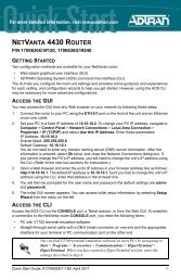
NETVANTA <strong>3448</strong> ROUTER<br />
P/N 1200821E1<br />
GETTING STARTED<br />
Two configuration methods are available for your <strong>NetVanta</strong> router:<br />
• Web-based graphical user interface (GUI)<br />
• AOS command line interface (CLI)<br />
The GUI lets you configure the main unit settings and provides online guidance and explanations<br />
for each setting. However, using the AOS CLI may be necessary for more advanced<br />
configurations.<br />
ACCESS THE GUI<br />
You may access theGUI from any web browser on your network by following these steps:<br />
1. Connect the router to your PC using the first switch port (labeled 1 on the back of the unit.<br />
2. Set your PC to a fixed IP address of 10.10.10.2. If you cannot change the PC’s IP address,<br />
you will need to change the unit’s IP address using the CLI. (Refer to the next two sections<br />
for instructions.)<br />
3. Enter the unit’s IP address in your browser address line. The default IP address is<br />
10.10.10.1.<br />
4. You will then be prompted for the user name and password (the default settings are admin<br />
and password).<br />
5. The initial GUI screen appears.<br />
ACCESS THE CLI<br />
Access the AOS CLI via the CONSOLE port or a Telnet session. To establish a connection to the<br />
<strong>NetVanta</strong> router CONSOLE port, you need the following items:<br />
• VT100 terminal or PC (with VT100 terminal emulation software)<br />
• Straight-through serial cable with a DB-9 (male) connector on one end and the appropriate<br />
interface for your terminal or PC communication port on the other end<br />
1. Connect the DB-9 (male) connector of your serial cable to the CONSOLE port on the rear<br />
panel of the unit.<br />
2. Connect the other end of the serial cable to the terminal or PC.<br />
3. Provide power to the unit as appropriate. Refer to the <strong>NetVanta</strong> 3000 Series Hardware<br />
Installation <strong>Guide</strong> (provided on the AOS Documentation CD) for more details.<br />
4. Once the unit is powered up, open a VT100 terminal session using the following settings:<br />
9600 baud, 8 data bits, no parity bits, and 1 stop bit. Press to activate the<br />
AOS CLI.<br />
5. Enter enable at the > prompt.<br />
6. Enter the enable password when prompted. The default password is password.<br />
<strong>Quick</strong> <strong>Start</strong> <strong>Guide</strong>, 61200821E1-13D, March 2008 1
The configuration parameters used in the examples outlined in this<br />
document are for instructional purposes only. Please replace all<br />
underlined entries (example) with your specific parameters to configure<br />
your application.<br />
CONFIGURE THE UNIT’S IP ADDRESS<br />
The following steps create an IP address and subnet mask for VLAN 1. If you are not sure what<br />
IP address to assign, please contact your network administrator.<br />
1. At the # prompt, enter config terminal.<br />
2. At the (config)# prompt, enter interface vlan 1 to access the configuration parameters for<br />
the Ethernet port located on the rear of the unit.<br />
3. Enter ip address 10.26.12.12 255.255.255.0 to assign an IP address to the VLAN interface<br />
using a 24-bit subnet mask.<br />
4. Enter ip route 0.0.0.0 0.0.0.0 192.22.72.2 to add a default route to the route table. If<br />
necessary, contact your network administrator to obtain the IP address (and subnet mask)<br />
for your particular configuration.<br />
5. Enter no shutdown to activate the interface to pass data.<br />
6. Enter exit to exit the Ethernet interface commands and return to the Global Configuration<br />
mode.<br />
Depending on your configuration, you may need to set a default<br />
gateway as well using the (config)#ip default gateway command. If IP<br />
routing is enabled on the unit, do NOT set a default gateway.<br />
ENABLE TELNET ACCESS<br />
The following steps create a password of adtran for Telnet access. By default, Telnet access is<br />
enabled with a password of password.<br />
1. Verify that the prompt of your unit displays (config)#.<br />
2. Enter line telnet 0 4 to change the configuration parameters for the Telnet sessions.<br />
3. Enter login to initiate Telnet access.<br />
4. Enter password adtran to change the login password for the Telnet sessions.<br />
5. Enter exit to return to the Global Configuration mode.<br />
6. Verify that the prompt of your unit displays (config)#.<br />
7. Enter do write memory to save the current configuration.<br />
2 Copyright © 2008 ADTRAN, Inc. All Rights Reserved.
CONFIGURE YOUR APPLICATION<br />
More detailed documentation for configuring your ADTRAN unit is provided on the AOS<br />
Documentation CD included in your shipment. For more detail on hardware setup, refer to the<br />
appropriate NIM quick start guides and the hardware installation guide. For more detail on<br />
configuring your system, refer to the AOS Command Reference <strong>Guide</strong>, configuration guides, and<br />
technical support notes.<br />
CONSOLE PINOUTS<br />
Important: For additional details on product features, specifications,<br />
installation, and safety, refer to the appropriate hardware installation<br />
guide on the AOS Documentation CD shipped with the base unit and<br />
available online at www.adtran.com.<br />
Pin Name Description<br />
1 DCD Data Carrier Detect (output)<br />
2 RD Receive Data (output)<br />
3 TD Transmit Data (input)<br />
4 DTR Data Terminal Ready (input)<br />
5 SG Signal Ground<br />
6 — Tied to Pin 1 (output)<br />
7 — Unused<br />
8 — Tied to Pin 1 (output)<br />
9 — Unused<br />
ETHERNET PINOUTS (ETH 0/1, ETH 0/2, ETHERNET SWITCH PORTS 1 TO 8)<br />
Pin Name Description With PoE Upgrade<br />
(Switch Ports 1 to 8 only)<br />
1 TX1 Transmit Positive PoE Negative Rail<br />
2 TX2 Transmit Negative PoE Negative Rail<br />
3 RX1 Receive Positive PoE Positive Rail<br />
4, 5 — Unused Unused<br />
6 RX2 Receive Negative PoE Positive Rail<br />
7, 8 — Unused Unused<br />
<strong>Quick</strong> <strong>Start</strong> <strong>Guide</strong>, 61200821E1-13D, March 2008 3
4 Copyright © 2008 ADTRAN, Inc. All Rights Reserved.