Download Datasheet - STW Technic
Download Datasheet - STW Technic
Download Datasheet - STW Technic

You also want an ePaper? Increase the reach of your titles
YUMPU automatically turns print PDFs into web optimized ePapers that Google loves.
Pioneering new technologies<br />
Pioneering new technologies<br />
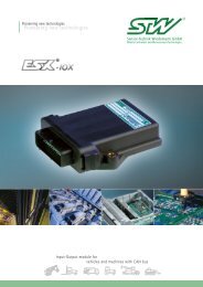
Freely programmable controllers for<br />
vehicles and machines with CAN-BUS
ON-Signal<br />
(interrupt<br />
input)<br />
16 digital inputs or<br />
RPM /frequency<br />
inputs<br />
8 analog inputs<br />
(0- 8.5 V / 0-10 V<br />
or 0-20 mA)<br />
Description<br />
Latch-up /<br />
Switch-Off<br />
(software)<br />
Vehicle battery<br />
Voltage supply 9-32 V DC<br />
16 bit<br />
Microcontroller<br />
Flash 512 kByte,<br />
opt. 1 MByte<br />
RAM 256 kByte,<br />
opt. 1 MByte<br />
EEPROM /FRAM<br />
to 16 kByte<br />
System<br />
supervisor<br />
incl. watchdog<br />
Safety<br />
relay<br />
4 digital /PWM<br />
outputs 2.5 A<br />
or PVG<br />
3 digital /PWM<br />
outputs 4 A<br />
or PVG<br />
5 digital /PWM outputs<br />
4 A with current<br />
measurement or PVG<br />
8.5 V / 10 V stabilized<br />
voltage output<br />
1 st CAN<br />
2 nd CAN<br />
RS232<br />
2 interfaces for<br />
Babyboards (2 x 6<br />
additional I/Os)<br />
The freely programmable controller ESX ®<br />
works independently as a measuring,<br />
driving or controlling device for sensoractuator<br />
management and is capable of<br />
executing a number of separate or related<br />
tasks in real time.<br />
The ESX ® was developed especially for use<br />
under harsh conditions and extreme temperatures,<br />
functioning from -40 to +85°C<br />
(-40 to 185°F) in vehicles and machines.<br />
All inputs and outputs are protected against<br />
short circuit to ground or to voltage overload<br />
and have a built-in diagnostic<br />
capability.<br />
Proportional valves can be driven without<br />
expensive amplifier or controller cards.<br />
Either a PWM (pulse width modulated)<br />
output with internal current measurement<br />
or a special output for proportional valves<br />
with integrated circuitry may be used.<br />
A robust cast aluminum housing (protection<br />
grade IP65, optionally IP67) with a GORE-<br />
TEX ® breathing filter offers high immunity<br />
to electromagnetic disturbances and protects<br />
against mechanical stressing.
CAN-Bus<br />
CAN-Bus<br />
Sensors<br />
Actuators<br />
additional CAN-Bus<br />
participants<br />
Bridge<br />
e. g. ESX ® Display Joystick PC<br />
ESX®<br />
Sensors<br />
Actuators<br />
CAN-Bus<br />
The ”Controller Area Network” (CAN), originally<br />
developed by Bosch for use in the automotive<br />
industry, has established itself as the<br />
standard bus system for mobile applications<br />
(international norm ISO 1898). Components<br />
for CAN-based systems are available in large<br />
quantities at very reasonable prices due to<br />
their wide spread use.<br />
CAN-Bus systems exhibit high transfer rates<br />
(CAN low-speed up to 125 Kbit/s, CAN highspeed<br />
to 1 Mbit/s) and high data transmission<br />
reliability. A number of different capabilities<br />
(CRC, frame checking, acknowledgment,<br />
bit monitoring and bit stuffing) enables the<br />
CAN protocol to recognize errors in transmitted<br />
data caused for example by electromagnetic<br />
disturbances, and to correct them<br />
(transmission stop with error flag and automatic<br />
repetition of the message). Since the<br />
length of the data packages are limited to<br />
max. 8 bytes of information per message, correction<br />
takes place with very little loss of time.<br />
A pair of wires suffices as transmission medium<br />
(ease of wiring). The length of the network<br />
can be up to 40 m with transfer rates<br />
of 1Mbit/s. Networks without repeaters up<br />
to 1000 m in length are practical with rates<br />
of 80 Kbit/s or less. The number of participants<br />
per network (in theory unlimited)<br />
I/O Modules<br />
DIOS/DIOM<br />
Sensors<br />
Actuators<br />
Sensor<br />
depends on the type of chip used (transceiver,<br />
physical layer). With commonly used<br />
chips, 32, 64 or up to 110 (with restrictions<br />
up to 128) nodes per network are possible<br />
(further extensions require repeaters or<br />
bridges).<br />
CAN is a ”multimaster system” with line<br />
topology and real time capability. Unique<br />
”identifiers” contain information not directly<br />
related to the address of a participant, but<br />
to the contents of a message (i.e. temperature,<br />
rotational or linear speeds). All participants<br />
check out the identifier being transmitted<br />
and decide if the type of message is<br />
relevant to themselves (acceptance filtering).<br />
In this way all messages can be received<br />
from many or all of the participants simultaneously.<br />
The unique identifier also determines<br />
the priority of the message relating to<br />
bus access. In case a number of participants<br />
tries to access the bus simultaneously, the<br />
higher priority message is guaranteed to<br />
gain bus access (prevention of bus accessing<br />
conflicts through bitwise arbitration). For<br />
these reasons it is important to incorporate<br />
functional procedures and safety requirements<br />
into the process of defining identifiers.<br />
Standard format (11-bit identifier) and extended<br />
format (29-bit identifier) are two different<br />
message formats which can coexist on the<br />
Actuators<br />
CAN-Bus compatible Sensors and Actuators<br />
GPS / DGPS<br />
Modem<br />
ESX ® -C2C<br />
same physical CAN-Bus. The specification CAN<br />
2.0 B supports both formats, while CAN 2.0 A<br />
only allows frames with 11-bit identifiers.<br />
Through content oriented identifiers in a<br />
message, the system achieves a high degree<br />
of configuration flexibility and allows a simple<br />
extension of the network to include further<br />
devices. There are a number of higher<br />
protocols such as LBS (Landwirtschaftliches<br />
Bus System), SAE J 1939, OSEK, CAL (CAN<br />
Application Layer, the basis for the communications<br />
profile CANopen), DeviceNet and<br />
others which have been normed or standardized.<br />
These are available on the so called<br />
”application layer”.<br />
The various semiconductor manufacturers<br />
offer CAN controllers with differing functionalities:<br />
one common type has one data buffer<br />
for transmitting and one for receiving - here<br />
the receive buffer is followed by a shadow<br />
buffer and the message filtering function<br />
utilizes the associated microprocessor (”Basic-<br />
CAN”). Another type has a number of buffers<br />
for managing and filtering multiple messages<br />
simultaneously (”Full CAN”, reduces workload<br />
on CPU). In addition there are so called<br />
SLIO (serial linked I/O) devices, which require<br />
no further microprocessor but function only<br />
as CAN slave modules (for I/O extension).
Rapid software development<br />
with CoDeSys or C<br />
The software can be programmed using<br />
CoDeSys (IEC 61131-3), a graphical user<br />
interface with the following choice of<br />
languages:<br />
• Function Block Diagram (FBD)<br />
• Ladder Diagram (LD)<br />
• Instruction List (IL)<br />
• Structured Text (ST)<br />
• Sequential Function Chart (SFC)<br />
CoDeSys may even be used without previous<br />
knowledge of any high level languages.<br />
Altium’s Tasking IDE may also be used for<br />
programming in the high level language C.<br />
<strong>STW</strong> has an extensive library available with<br />
programming and configuration functions<br />
including debug and diagnostic tools.<br />
These components provide the possibility to<br />
quickly and easily program application software.<br />
ESX ® -KEFEX, <strong>STW</strong>’s PC based software,<br />
can be used to create stand-alone<br />
diagnostic, service and “end of line” configuration<br />
tools. Upon request <strong>STW</strong> can<br />
develop complete software solutions for<br />
customer applications.<br />
Programming<br />
Simulation<br />
Simulation of all<br />
inputs and outputs<br />
To simulate your vehicle and speed development,<br />
<strong>STW</strong> offers a test box, which provides<br />
monitoring circuits and indicators for all<br />
inputs and outputs as well as a connector<br />
for the ESX ® . These may be switched as<br />
desired or connected to simulators for sensors<br />
or actuators. The test box also includes<br />
an integrated termination for the CAN network<br />
if required. The voltage supply has<br />
separate fuses for the processor and for the<br />
driver electronics. Special boards for monitoring<br />
customer specific design features may<br />
be plugged into the available slots.
Applications in vehicles:<br />
• Electrohydraulic steering systems<br />
(steer-by-wire)<br />
• Electronically controlled hydrostatic drives<br />
(drive-by-wire)<br />
• Hydraulic control<br />
• Engine management<br />
• Transmission control<br />
• Automatic levelling and positioning of<br />
platforms<br />
Reliable TÜV certified safety<br />
All standards required for CE conformity<br />
are met with the ESX ® . Over and above<br />
these, the varying branch specific requirements<br />
and standards of the automotive,<br />
agricultural or construction industries are<br />
also met.<br />
For safety relevant applications (e.g. waste<br />
disposal vehicles, hoists) the ESX ® has been<br />
developed to perform to Safety Integrity<br />
Level 2 of IEC 61508 standards or<br />
Category 3 of EN 954-1 respectively.<br />
All input and output channels of the control<br />
systems are diagnosable, meaning that<br />
short circuits or open circuits can be detec-<br />
ted by the software. In addition, a continuous<br />
software diagnosis of the internal<br />
hardware is performed.<br />
A safety relay provides a second means of<br />
switching off the digital and PWM outputs.<br />
Networking with CAN-Bus<br />
Data exchange with other intelligent units is<br />
made possible with CAN (CAN 2.0 B) interfaces.<br />
Both standard and extended format<br />
are supported. The CAN is capable of connecting<br />
a number of controllers into a network.<br />
Modules with additional CAN interfaces<br />
may be built into the ESX ® , allowing it<br />
to take on a bridge function, and allowing<br />
multiple independent buses to communicate<br />
freely at transfer rates of up to 1 Mbit/s.<br />
Expansion boards<br />
The electronic controller ESX ® may be<br />
expanded, using two standard internal<br />
interfaces and various modules to provide<br />
up to 12 additional input or output ports.<br />
The type of I/O is not restricted. These<br />
modules may also include further design<br />
features (e.g. real time clock) making the<br />
ESX ® ideally suited for quick adaptation to<br />
customer demands.<br />
Configuration, calibration<br />
and parameter setting<br />
Characteristics, calibration data and critical<br />
parameters for sensor-actuator management<br />
as well as controller configuration<br />
can all be stored in a non-volatile FRAM/<br />
EEPROM. Using an editor software, this<br />
data may be accessed via CAN bus or the<br />
RS 232 interface.<br />
Comprehensive external and<br />
internal error diagnostics<br />
<strong>STW</strong> offers a line of software tools for<br />
reading the error buffer, system diagnostics,<br />
visualization and maintenance or repair<br />
services. Communication is established<br />
using the standard CAN-Bus or the RS 232<br />
interface.
• ESX ® - a rugged standard controller<br />
proven in mobile applications with<br />
sensor-actuator management through<br />
integrated measurement, control and<br />
driver devices offers real time data processing<br />
of multiple independent or linked<br />
tasks.<br />
• Freely programmable, using CoDeSys<br />
(IEC 61131-3) or in high level language C<br />
<strong>Technic</strong>al Data ESX ®<br />
• Advanced measures for EMC and a<br />
robust housing for all automobile<br />
environments<br />
• An ingenious grounding scheme provides<br />
separate analog ground for sensors<br />
• Internal diagnostics, protection against<br />
voltage overload and protection against<br />
short circuit to ground or to supply<br />
voltage for all inputs and outputs<br />
Processor system<br />
Processor 16bit controller, 20Mhz/40MHz, system supervisor with programmable watchdog<br />
RAM 256 kByte, opt. 1 MByte<br />
Flash 512 kByte, opt. 1 MByte<br />
EEPROM 16 kByte<br />
Interfaces<br />
CAN 1st CAN, optional 2nd CAN, 2.0B (11 bit and 29 bit identifier), full CAN, low-/high-speed up to 1 Mbit/s<br />
RS232 programmable baud rate<br />
Babyboard for expansions<br />
In-/Outputs<br />
Digital or RPM inputs max. 16 digital or RPM inputs, software configurable, active high /low switchable, cut-off-frequency 6.5 kHz, short circuit protected<br />
Analog inputs max. 8 analog inputs, 4-20 mA or 0-8.5 V/0-10 V,software configurable, 10 bit, cut-off-frequency 1 kHz, short circuit protected<br />
Digital / PWM outputs max. 3 x 4 A, high side switch, 0 - 100 % diagnosable, short circuit protected<br />
max. 4 x 2.5 A, high side switch, 0 -100 % diagnosable, short circuit protected<br />
Digital / PWM outputs with<br />
current measurement<br />
max. 5 x 4 A, high side switch, 0 - 100 % diagnosable, PWM-frequency from 5 - 250 Hz, short circuit protected<br />
PVG outputs max. 12x PVG, used for Danfoss valves (20 % UB - 80 % UB) Constant voltage output 8.5/10 V stabilized voltage supply, load current up to 1 A, short circuit protected<br />
Additional modules max. 2 modules, with up to 6 inputs or outputs each, e.g. digital or analog I/O, encoder inputs, CAN or customer specific designed<br />
System data<br />
Voltage supply 9-32 V DC<br />
Current requirements operational about 0.5 A without external load, stand-by < 1 mA, max. total current up to 30 A<br />
Physical characteristics<br />
Connector 68 pin automotive type (AMP)<br />
Chassis IP 65, optional IP 67, die-cast aluminum, GORE-TEX ® breathing filter for pressure equalization<br />
Weight approx. 2 kg (4.4 lbs)<br />
Dimension approx. 170 mm x 195 mm x 72 mm<br />
(6.69” x 7.68” x 2.83”)<br />
EMC, Environmental requirements<br />
Requirements According to automotive, agricultural and construction industry standards; -conformity<br />
Operating temperature -40° C to +85° C (-40° F to 185° F) chassis temperature<br />
Sensor-Technik Wiedemann GmbH<br />
Steuer- und Regelelektronik<br />
Am Bärenwald 6<br />
D-87600 Kaufbeuren<br />
GERMANY<br />
Telephone +49 (0) 8341-9505-0<br />
Telefax +49 (0) 8341-9505-55<br />
E-Mail info@sensor-technik.de<br />
Internet www.sensor-technik.de<br />
<strong>STW</strong>-TECHNIC, LP<br />
MOBILE CONTROLLERS AND<br />
MEASUREMENT TECHNOLOGIES<br />
3000 Northwoods Pkwy. Suite 260<br />
Norcross, GA 30071 USA<br />
Telephone +1 (770)242-1002<br />
Telefax +1 (770)242-1006<br />
E-Mail sales@stw-technic.com<br />
Internet www.stw-technic.com<br />
• Safety relay as emergency switch off<br />
• TÜV certified to Safety Integrity Level 2<br />
or Category 3 for safety relevant applications<br />
• Direct driving of proportional valves<br />
(saves expensive driver and/or controller<br />
boards)<br />
Sensor-Technik UK Ltd.<br />
Unit 10, The Granary<br />
Mill Road, Sharnbrook<br />
Bedfordshire MK44 1NN<br />
ENGLAND<br />
Telephone +44 (0) 12 34-7820-49<br />
Telefax +44 (0) 12 34-7820-56<br />
E-Mail sales@sensor-technik.co.uk<br />
Internet www.sensor-technik.co.uk<br />
20061130 US - Subject to change without notice -