RIBE Fastening Systems - Thread-Forming Screws
RIBE Fastening Systems - Thread-Forming Screws
RIBE Fastening Systems - Thread-Forming Screws

You also want an ePaper? Increase the reach of your titles
YUMPU automatically turns print PDFs into web optimized ePapers that Google loves.
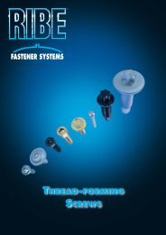
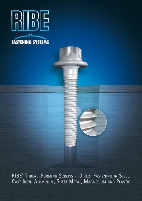
<strong>RIBE</strong> ® Th R E a d-Fo R m I n g Sc R E w S – dI R E c T Fa S T E n I n g In ST E E l,<br />
caS T IR o n, al u m I n u m, Sh E E T mE T a l, ma g n E S I u m an d PlaSTIc
<strong>Thread</strong>-forming screws –<br />
cuT cosTs wiTh direcT fasTening<br />
<strong>Thread</strong>-forming screws create their own mating thread by reforming the mating<br />
material during assembly. Direct fastening in components without an existing mat-<br />
ing thread can substantially cut the overall cost of mechanical fastening in many<br />
cases. Particularly the process costs can be reduced by using thread-forming screws,<br />
as no thread cutting or thread forming is necessary and no metal chips are pro-<br />
duced. The screws are inserted directly into stamped, drilled, cast or lasered holes.<br />
<strong>Thread</strong>-forming screws also offer definite advantages in terms of process reliability.<br />
The material hardening in the thread creates a higher proof load for the complete<br />
fastening. Because of the necessary insertion torque and the perfect fit between the<br />
screw and mating thread, the resistance to loosening is greater, which often makes<br />
it possible to dispense with screw locking devices.<br />
<strong>RIBE</strong> ® thread-forming screws have been designed specifically to meet the require-<br />
ments of various applications and materials and are available in a broad range of<br />
geometries, materials and finishes. Direct fastenings always require an optimum<br />
interaction between component, fastener and assembly, so the screw must be per-<br />
fectly designed for each application. An exact analysis of the fastening and the<br />
required properties is always recommended for high-load and special applications.<br />
Our Application Engineering Department will be pleased to help.<br />
Materials and versions<br />
All metals and plastics with sufficient ductility and a material strength of up to<br />
approx. 950 MPa are suitable as mating materials for direct fastenings. There is a<br />
fundamental difference between direct fastening in metals and plastics: For fas-<br />
tening in metals and especially steel, the screw needs to be extremely hard in the<br />
forming zone (achieved by quenching and tempering for high strength, CORFLEX ®<br />
N case hardening, CORFLEX ® I partial inductive hardening). The CORFLEX ® versions<br />
enable thread-forming screws to be used for fastenings subject to high static and
dynamic loads. The thread profile corresponds to that of a metric thread. For fasten-<br />
ing in plastics, slender, well-tapered flanks with a coarser pitch are more suitable.<br />
Quenched and tempered screws are sufficiently strong for these applications and<br />
special hardening of the surface layer is not necessary.<br />
cooling lubricant<br />
if necessary<br />
drill<br />
hole<br />
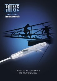
advanTages of <strong>Thread</strong>-forming screws<br />
Direct fastening with thread-forming screws has the following advantages<br />
� <strong>Thread</strong> formed without cutting.<br />
2 No weakening of the mating thread area<br />
as no material is removed.<br />
3 Lower costs as no thread-cutting or<br />
forming is necessary.<br />
4 Immediate use of stamped, drilled<br />
or cast holes.<br />
Process chain using<br />
a metric screw.<br />
cut<br />
thread<br />
cutting oil if necessary<br />
remove<br />
chips<br />
assembly<br />
5 Higher strength of mating thread due to<br />
cold fixing.<br />
6 Increased resistance to loosening eliminates<br />
the need for screw locking devices.<br />
7 No damage to mating threads due to<br />
cross-threading during assembly.<br />
Shortened process chain using<br />
a thread-forming screw.<br />
pilot<br />
hole<br />
cast<br />
assembly
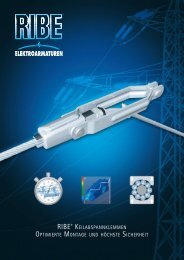
<strong>Thread</strong>-forming screws –<br />
overview of direcT fasTening<br />
sTeel | casT iron | aluminum<br />
The TRIFORM, TAPTITE II ® , DUO-TAPTITE ® and TAPTITE 2000 ® thread-forming screws<br />
are designed for direct fastening in metals. The TRIFORM screw is characterized by<br />
low thread-forming torque and good thread proof load at low production cost. The<br />
TAPTITE ® screws have been specifically developed to meet extreme requirements for<br />
assembly performance and proof load.<br />
sheeT meTal<br />
The TRIFORM DB is suitable for all applications with less extreme requirements for<br />
assembly performance. EXTRUDE-TITE ® screws are characterized by a very low inser-<br />
tion torque due to their geometry. The TRIFORM DB HF screw has been developed<br />
specially for increased requirements in high-strength sheet metals with a strength<br />
of up to 950 MPa and in stainless sheet steel.<br />
magnesium<br />
The use of high-strength <strong>RIBE</strong> ® ALUFORM ® aluminum screws is the optimum solution<br />
for reliable fastening of magnesium components. Prestressing force losses through<br />
additional thermally induced stresses are minimized by the very similar coefficients<br />
of thermal expansion and contact corrosion is avoided almost completely even with<br />
uncoated screws. The thread-forming version of these screws now also permits direct<br />
fastening of sufficiently ductile magnesium alloys.<br />
PlasTic<br />
<strong>RIBE</strong> ® PR and PLASTOFORM screws are equally suitable for use in plastics. <strong>RIBE</strong> ® PR<br />
is characterized by low-cost manufacture, whereas PLASTOFORM screws provide<br />
high pullout forces due to their flow-optimized geometry and are also suitable for<br />
brittle plastics.
STEEL<br />
CAST IRON<br />
ALUMINUM<br />
SHEET<br />
METAL<br />
MAGNESIUM<br />
PLASTIC<br />
TRIFORM<br />
TAPTITE II ®<br />
DUO-TAPTITE ®<br />
TAPTITE 2000 ®<br />
TRIFORM DB<br />
TRIFORM DB HF<br />
EXTRUDE-TITE ®<br />
ALUFORM ®<br />
<strong>RIBE</strong> ®<br />
PR<br />
PLASTOFORM<br />
Cost-effective<br />
Cost-effective<br />
Cost-effective<br />
Assembly<br />
performance<br />
Assembly<br />
performance<br />
Assembly<br />
performance<br />
Proof load<br />
of fastening<br />
Proof load<br />
of fastening<br />
Proof load<br />
of fastening<br />
Cost-effective Proof load of fastening<br />
very suitable suitable less suitable
TRIFORM<br />
- Low thread-forming torque<br />
- High thread proof load<br />
- Low-cost manufacture<br />
- No license fees<br />
TAPTITE II ®<br />
- Trilobular cross-section<br />
- Very low thread-forming torque<br />
- Short thread-forming crest<br />
- Also suitable for large thread reach<br />
<strong>Thread</strong>-forming screws –<br />
for meTal comPonenTs<br />
The following screws have different thread-forming crests for creating the mating<br />
thread. The thread-forming crests have sharp flanks for rapid engagement of the<br />
screw during assembly and an out-of-round profile for forming the mating thread.<br />
These screws have a metric thread profile for interchangeability with screws with<br />
standard threads. For example, a screw with a metric thread can be used for subse-<br />
quent repair if the original screw is not available.<br />
Triform<br />
The TRIFORM screw, a <strong>RIBE</strong> ® development with many years<br />
of reliable service, is characterized by low thread-forming<br />
torque and good thread proof load at a low price. This is<br />
achieved by the combination of a low-cost TRIFORM<br />
thread-forming crest and a round shank cross-section. Main<br />
TaPTiTe ii ®<br />
applications: cost-optimized parts and mating thread<br />
materials with low reforming capacity.<br />
The TAPTITE II ® screw is characterized by a high degree of<br />
lobulation (out-of-roundness) of the shank cross-section,<br />
which achieves very low insertion torque. Lobulation over<br />
the entire length of the shank ensures consistently low in-<br />
sertion torque, even with a large thread reach. Although the<br />
screw engages with negligible axial contact force, the thread-<br />
forming crest of 2 to 3 turns is shorter and better than<br />
the requirements of DIN 7500-1.
duo-TaPTiTe ®<br />
The DUO-TAPTITE ® screw has a thread-forming crest and a<br />
guide pin that facilitates finding and centering in the pi-<br />
lot hole for good axial alignment of the screw. The lobula-<br />
tion of the thread-forming crest is greater than that of the<br />
load-bearing shank, which provides low insertion torque<br />
combined with high axial proof load of the fastening (high<br />
stripping torque, high pullout forces).<br />
TaPTiTe 2000 ®<br />
The TAPTITE 2000 ® screw combines the advantages of the<br />
TAPTITE II ® and DUO-TAPTITE ® in terms of mechanical proper-<br />
ties and reduced costs. The trilobular thread profile with dual<br />
lobulation combined with the radius profile thread im-<br />
proves the insertion torque / stripping torque<br />
ratio. It also reduces the thread-forming<br />
torque by up to 30 % compared with the<br />
DUO-TAPTITE ® .<br />
- Decreasing trilobularity for increased<br />
load rating in the grip range<br />
- Guide pin for automatic assembly<br />
- For high-strength / dynamic fastenings<br />
Metals<br />
DUO-TAPTITE ®<br />
TAPTITE 2000 ®<br />
- Radius profile for reduced<br />
thread-forming torque<br />
- Improved insertion / stripping<br />
torque ratio<br />
- Various crests available for optimum<br />
adaptation to application
The tables shown here provide<br />
thread dimensions, suggestions for<br />
hole geometry for drilling, punching<br />
or casting, and guide values for<br />
insertion and tightening torque. The<br />
guide values shown apply equally<br />
to TRIFORM, TAPTITE II ® , DUO-TAP-<br />
TITE ® and TAPTITE 2000 ® . Due to the<br />
variety of possible parameters for<br />
material performance, surface and<br />
lubrication, the torque values stated<br />
should be regarded as guide values<br />
only. In case of critical component<br />
combinations such as low thread<br />
reach and mating thread materials<br />
of low ductility, we urgently recommend<br />
experimenting to determine<br />
the right values.<br />
Technical daTa –<br />
for meTal comPonenTs<br />
Insertion torque**<br />
Values in Nm<br />
TRIFORM<br />
TRIFORM thread dimensions<br />
<strong>Thread</strong> d 1 max z 1 max<br />
M 2.5 2.60 1.50<br />
M 3 3.10 1.60<br />
M 3.5 3.61 2.00<br />
M 4 4.12 2.30<br />
M 5 5.12 2.60<br />
M 6 6.12 3.30<br />
M 8 8.16 4.10<br />
M 10 10.18 5.00<br />
<strong>Thread</strong><br />
Section A – B<br />
Transit holes: Guide values for insertion and tightening torque for<br />
TRIFORM, TAPTITE II ® , DUO-TAPTITE ® and TAPTITE 2000 ® in Nm<br />
Transit hole beyond thread-forming crest<br />
TAPTITE II ®<br />
TAPTITE II ® thread dimensions<br />
C D<br />
min max min max<br />
M 2 1.98 2.06 1.90 1.98<br />
M 2.5 2.48 2.57 2.39 2.48<br />
M 3 2.98 3.07 2.88 2.97<br />
M 3.5 3.48 3.58 3.36 3.46<br />
M 4 3.98 4.08 3.84 3.94<br />
M 5 4.98 5.09 4.82 4.93<br />
M 6 5.97 6.10 5.77 5.90<br />
M 8 7.97 8.13 7.72 7.88<br />
M 10 9.97 10.15 9.67 9.85<br />
M 12 11.97 12.18 11.62 11.83<br />
M 2 M 2.5 M 3 M 3.5 M 4 M 5 M 6 M 8 M 10 M 12 M 14 M 16<br />
0.1- 0.2 0.2 - 0.4 0.3 - 0.7 0.5 - 1.1 0.7 - 1.6 1.5 - 3.5 2.5 - 6 7 - 15 15 - 30 25 - 52 35 - 70 55 - 115<br />
Tightening torque 8.8* 0.4 0.7 1.3 1.9 2.8 5.5 9.9 23.4 45.9 78.3 130.5 198.0<br />
Tightening torque 10.9 0.5 1.0 1.8 2.7 4.1 8.0 14.0 33.3 67.5 115.2 189.0 288.0<br />
Tightening torque 12.9 0.7 1.2 2.1 3.2 4.7 9.4 16.2 38.7 78.3 135.0 216.0 342.0<br />
Because of the many factors that can influence the process, such as mating thread material, hole diameter, thread reach, screw surface,<br />
lubrication conditions and screw geometry, the values shown are only intended as an approximate guide. The stated torque values apply<br />
only to screws with the corresponding hole geometry and sufficient thread reach.<br />
Optimum assembly instructions must be determined by experiment.<br />
* The values shown for 8.8 screws also apply to DIN 7500 screws.<br />
** Even the highest insertion torque values are less than the maximum limits defined by DIN 7500.
<strong>Thread</strong><br />
Blind holes: Guide values for insertion and tightening torque for<br />
TRIFORM, TAPTITE II ® , DUO-TAPTITE ® AND TAPTITE 2000 ® in Nm<br />
Insertion torque**<br />
Values in Nm<br />
Section A – B<br />
DUO-TAPTITE ®<br />
Section E – F<br />
DUO-TAPTITE ® thread dimensions<br />
C D Cp<br />
min max min max max<br />
M 2 1.98 2.06 1.94 2.02 1.75<br />
M 2.5 2.48 2.57 2.44 2.52 2.22<br />
M 3 2.98 3.07 2.93 3.02 2.69<br />
M 3.5 3.48 3.58 3.42 3.52 3.13<br />
M 4 3.98 4.08 3.91 4.01 3.57<br />
M 5 4.98 5.09 4.90 5.01 4.51<br />
M 6 5.97 6.10 5.87 6.00 5.38<br />
M 8 7.97 8.13 7.85 8.00 7.23<br />
M 10 9.97 10.15 9.82 10.00 9.07<br />
M 12 11.97 12.18 11.80 12.00 10.92<br />
M 14 13.97 14.20 13.77 14.00 12.77<br />
M 16 15.97 16.20 15.77 16.00 14.77<br />
Blind hole<br />
<strong>Thread</strong><br />
Section A – B<br />
M 2 M 2.5 M 3 M 3.5 M 4 M 5 M 6 M 8 M 10 M 12 M 14 M 16<br />
0.1 - 0.2 0.2 - 0.4 0.3 - 0.7 0.5 - 1.1 0.7 - 1.6 1.5 - 3.5 2.5 - 8 7 - 15 15 - 30 25 - 52 35 - 70 55 - 115<br />
Tightening torque 8.8* 0.4 0.8 1.5 2.2 3.3 6.4 11.6 27.3 53.6 91.4 152.3 231.0<br />
Tightening torque 10.9 0.6 1.2 2.1 3.2 4.7 9.3 16.3 38.9 78.8 134.4 220.5 336.0<br />
Tightening torque 12.9 0.8 1.4 2.4 3.7 5.5 10.9 18.9 45.2 91.4 157.5 252.0 399.0<br />
TAPTITE 2000 ®<br />
TAPTITE 2000 ® thread dimensions<br />
Because of the many factors that can influence the process, such as mating thread material, hole diameter, thread reach, screw surface,<br />
lubrication conditions and screw geometry, the values shown are only intended as an approximate guide. The stated torque values apply<br />
only to screws with the corresponding hole geometry and sufficient thread reach.<br />
Optimum assembly instructions must be determined by experiment.<br />
* The values shown for 8.8 screws also apply to DIN 7500 screws.<br />
** Even the highest insertion torque values are less than the maximum limits defined by DIN 7500.<br />
Section E – F<br />
C D Cp<br />
nominal normal max<br />
M 2 2.00 1.96 1.77<br />
M 2.5 2.50 2.45 2.25<br />
M 3 3.00 2.95 2.71<br />
M 3.5 3.50 3.44 3.17<br />
M 4 4.00 3.93 3.60<br />
M 5 5.00 4.92 4.55<br />
M 6 6.00 5.90 5.38<br />
M 8 8.00 7.87 7.23<br />
M 10 10.00 9.85 9.08<br />
M 12 12.00 11.82 10.92<br />
M 14 14.00 13.80 12.77<br />
M 16 16.00 15.80 14.76<br />
Metals
The tables shown here provide<br />
thread dimensions, suggestions for<br />
hole geometry for drilling, punching<br />
or casting, and guide values for<br />
insertion and tightening torque. The<br />
guide values shown apply equally<br />
to TRIFORM, TAPTITE II ® , DUO-TAP-<br />
TITE ® and TAPTITE 2000 ® . Due to the<br />
variety of possible parameters for<br />
material performance, surface and<br />
lubrication, the torque values stated<br />
should be regarded as guide values<br />
only. In case of critical component<br />
combinations such as low thread<br />
reach and mating thread materials<br />
of low ductility, we urgently recommend<br />
experimenting to determine<br />
the right values.<br />
Technical daTa –<br />
for meTal comPonenTs<br />
Materials and versions<br />
TRIFORM, TAPTITE II ® , DUO-TAPTITE ® and TAPTITE 2000 ® are available in the following<br />
materials: case-hardened to DIN EN ISO 7085, CORFLEX ® N quenched and hardened<br />
with controlled recarborization to DIN EN 20898 (strength classes 8.8, 10.9 and 12.9)<br />
and CORFLEX ® I with inductively hardened thread-forming crest.<br />
A case-hardened version is sufficient for general applications with no special require-<br />
ments for dynamic strength or ductility of the screw. Quenched and tempered screws<br />
of strength class 8.8, 10.9 or 12.9 are ideal for forming mating threads in light metals<br />
(CORFLEX ® N, mating thread strength up to approx. 400 MPa or hardness 120 HB).<br />
Quenched and tempered screws with inductively hardened thread-forming crests<br />
(CORFLEX ® I) are capable of forming mating threads in metals with strengths of up<br />
to approx. 650 MPa (200 HB) and meet the highest requirements for ductility and<br />
stress resistance.<br />
The CORFLEX ® versions enable thread-forming screws to be used for fastenings sub-<br />
ject to high static and dynamic loads.<br />
Rim holes in sheet metal: Guide values for hole diameter d B<br />
TRIFORM, TAPTITE II ® , DUO-TAPTITE ® and TAPTITE 2000 ® in mm<br />
Thickness s (mm) M 2.5 M 3 M 3.5 M 4 M 5 M 6 M 8 M 10 M 12<br />
0.5 2.21 - 2.24 2.68 - 2.71<br />
0.8 2.23 - 2.26 2.71 - 2.74 3.15 - 3.18<br />
1.0 2.25 - 2.28 2.74 - 2.77 3.16 - 3.21 3.57 - 3.62 4.48 - 4.54<br />
1.5 2.27 - 2.30 2.77 - 2.80 3.19 - 3.24 3.60 - 3.65 4.51 - 4.57 5.38 - 5.45 7.19 - 7.27<br />
2.0 3.64 - 3.69 4.54 - 4.60 5.41 - 5.48 7.22 - 7.30 9.08 - 9.17<br />
3.0 4.57 - 4.63 5.44 - 5.51 7.25 - 7.33 9.13 - 9.22 10.90 -11.00<br />
4.0 7.30 - 7.38 9.18 - 9.27 10.95 -11.05<br />
5.0 9.26 - 9.35 11.00 -11.10<br />
Geometry of holes as per diagram; cf. DIN 7952. A material with a high elongation at rupture must be used to ensure holes<br />
without cracks. Guide value for pilot hole in sheet metal: 0.5 x nominal diameter of screw.
Cast holes: Guide values for hole diameter<br />
TRIFORM, TAPTITE II ® , DUO-TAPTITE ® and TAPTITE 2000 ® in mm<br />
Dimensions in mm M 4 M 5 M 6 M 8 M 10 M 12 M 14 M 16<br />
d o 3.73 4.72 5.66 7.60 9.55 11.50 13.45 15.45<br />
d u 3.55 4.50 5.40 7.26 9.13 11.00 12.80 14.80<br />
Upper gap for d o and d u * + 0.030 + 0.030 + 0.036 + 0.036 + 0.043 + 0.043 + 0.043 + 0.043<br />
d a * 6.50 8.50 10.00 13.00 17.00 20.00 24.00 27.00<br />
t s 0.70 0.80 1.00 1.30 1.50 1.80 2.00 2.00<br />
d s 4.20 5.20 6.30 8.30 10.40 12.40 14.50 16.50<br />
Upper gap for d a , t s , d s * + 0.075 + 0.075 + 0.090 + 0.090 + 0.110 + 0.110 + 0.110 + 0.110<br />
I for high-strength materials,<br />
e. g. cast steel a approx. 1.5°<br />
I for medium-strength materials,<br />
e. g. gray cast iron, aluminum, zinc, a approx. 1.1°<br />
I for low-strength materials,<br />
e. g. magnesium, aluminum, a approx. 0.8°<br />
6.70 8.30 9.80 12.80 16.40 19.50 21.70 25.00<br />
8.20 10.30 12.40 16.40 20.50 24.50 28.70 33.00<br />
12.40 15.40 18.50 24.50 30.70 36.80 43.00 49.00<br />
* Larger tolerances, different external diameters of the casting dome or different tapers may be used if the proof load<br />
requirements for the fastening are less demanding.<br />
Cylindrical holes: Guide values for hole diameter d B<br />
TRIFORM, TAPTITE II ® , DUO-TAPTITE ® and TAPTITE 2000 ® in mm<br />
<strong>Thread</strong> reach / Material<br />
thickness s (mm)<br />
0.5 - 1.0 1.80 2.25 2.70<br />
M 2 M 2.5 M 3 M 3.5 M 4 M 5 M 6 M 8 M 10 M 12 M 14 M 16<br />
1.0 - 1.6 1.80 2.25 2.70 3.20<br />
1.6 - 2.5 1.85 2.25 2.75 3.20 3.65 4.50 5.40<br />
2.5 - 4.0 1.85 2.30 2.75 3.20 3.65 4.55 5.50 7.30 9.30<br />
4.0 - 6.3 2.30 2.75 3.25 3.70 4.65 5.50 7.40 9.30 11.10<br />
6.3 - 10.0 3.70 4.65 5.55 7.50 9.40 11.10<br />
10.0 - 16.0 7.50 9.40 11.20 13.20 15.20<br />
16.0 - 25.0 7.60 9.50 11.30 13.20 15.20<br />
Upper gap of hole (mm) + 0.050 + 0.075 + 0.075 + 0.075 + 0.075 + 0.090 + 0.090 + 0.110 + 0.110 + 0.110 + 0.110<br />
Larger hole diameters reduce the insertion torque, smaller diameters increase the durability of the mating thread and the<br />
resistance to loosening. For malleable, low-strength materials such as aluminum alloys, the hole diameters can be reduced<br />
by approx. 0.05 mm. Hole tolerances: H11 to DIN ISO 286.<br />
Metals
TRIFORM DB<br />
- High axial proof load<br />
- Round cross-section<br />
- Cost-effective<br />
<strong>Thread</strong>-forming screws –<br />
for sheeT meTal comPonenTs<br />
TRIFORM DB, EXTRUDE-TITE ® and TRIFORM DB HF are thread-forming screws with<br />
a particularly long thread-forming crest for use with sheet metals. They form their<br />
own rim hole if the diameter of the drilled hole is suitably reduced. This enables a<br />
fastening with a high proof load to be produced even in very thin sheet metal ma-<br />
terials by plastic reforming of the mating thread material. The long thread-forming<br />
crest produces a marked axial alignment of the screw during assembly. In contrast<br />
to conventional sheet metal screws, the large web section facilitates considerable<br />
reforming of the mating thread material with increased stripping torque. The TRI-<br />
FORM DB HF is a special screw developed specifically for high-strength sheet<br />
metals. The usual thin sheet screws are suitable for sheet metals up to max. 600<br />
MPa. Higher strengths make it more difficult for the screw to engage or the screw<br />
is heavily damaged due to the small differences in strength. The use of normal thin<br />
sheet screws in stainless steel sheets has also been limited until now because of the<br />
poor friction pairings. The TRIFORM DB HF now makes thread-forming fastening<br />
possible in sheet metals with a strength of 600 MPa to 950 MPa and in stainless<br />
steel sheets.<br />
Triform dB<br />
The screw is based on the tried and tested TRIFORM ge-<br />
ometry and is a high-performance fastener at low cost. This<br />
high performance is achieved by the forming surfaces on the<br />
thread-forming crest and the cylindrical screw shank. The<br />
flanks of the thread are fully formed right through to the<br />
crest. The TRIFORM DB screw can be used wherever<br />
maximum cost-effectiveness is required for sheet<br />
metal components.
eXTrude-TiTe ®<br />
The EXTRUDE-TITE ® screw is slightly out-of-round along the<br />
full length of the shank. This also achieves very low insertion<br />
torque in sheet metals, which provides maximum assembly<br />
reliability even in difficult applications. The thread flanks of<br />
the EXTRUDE-TITE ® screw are also fully formed through to<br />
the crest.<br />
Triform dB hf<br />
Changing the heat treatment and the geometry below the<br />
screw head makes this screw with the proven TRIFORM<br />
geometry suitable for use in high-strength and stainless<br />
sheet metals. The TRIFORM DB HF is made of quenched<br />
and tempered low-alloy steel. The thread crest is<br />
inductively hardened. The corrosion protec-<br />
tion is designed for high surface pressure on<br />
inserting into hard sheet metals.<br />
- Slightly trilobular shank<br />
- Low insertion torque<br />
- Reliable assembly<br />
EXTRUDE-TITE ®<br />
TRIFORM DB HF<br />
- For sheet metals up to 950 Mpa tensile<br />
strength and austenitic sheet metals<br />
- Increased load rating through more<br />
collaring<br />
Sheet metal
Technical daTa –<br />
for sheeT meTal comPonenTs<br />
The following three main parameters are important for direct fastening in sheet<br />
metals:<br />
• The diameter of the pilot hole in the component<br />
• The insertion torque expected during assembly<br />
• The tightening torque that can be safely applied<br />
These three parameters are shown in the following tables.<br />
For direct fastening in sheet metals, the component is practically always the weak<br />
point when the fastening is overstressed. The assembly instructions must therefore<br />
be carefully prepared. Because of the many factors that can influence the process,<br />
the values given in the tables are only guide values and should be checked in each<br />
case.<br />
Modern assembly methods with several screw levels also help to ensure reliable<br />
assembly for direct fastening in sheet metals. They even allow screws to be reliably<br />
assembled when the insertion torque exceeds the tightening torque. This means<br />
the right screw combined with the right assembly method can open up additional<br />
applications and potential cost savings for fastening in sheet metals.<br />
The tables shown here provide thread dimensions, suggestions for hole geometry<br />
for drilling and punching, and guide values for insertion and tightening torque. The<br />
guide values apply equally to TRIFORM DB, TRIFORM DB HF and EXTRUDE-TITE ® .<br />
Due to the variety of possible parameters for material performance, surface and<br />
lubrication, the torque values stated should be regarded as guide values only. In case<br />
of critical component combinations such as low thread reach and mating thread<br />
materials of low ductility, we urgently recommend experimenting to determine the<br />
right values.
<strong>Thread</strong><br />
TRIFORM DB and TRIFORM DB HF thread dimensions<br />
<strong>Thread</strong> d 2 max z max d 1 max<br />
M 3 1.50 3.50 3.10<br />
M 4 2.00 4.90 4.12<br />
M 5 2.50 5.60 5.12<br />
M 6 3.00 7.00 6.12<br />
M 8 4.40 8.80 8.16<br />
EXTRUDE-TITE ® thread dimensions<br />
C D Cp Lp<br />
min max min max max max<br />
M 3 2.98 3.07 2.93 3.02 1.26 2.75<br />
M 4 3.98 4.08 3.91 4.01 1.56 3.85<br />
M 5 4.98 5.09 4.90 5.01 2.21 4.40<br />
M 6 5.97 6.10 5.87 6.00 2.51 5.50<br />
M 8 7.97 8.13 7.85 8.01 3.64 6.88<br />
Hole diameters and torque values: TRIFORM DB, EXTRUDE-TITE ®<br />
Hole diameter<br />
(mm)<br />
Insertion torque guide values<br />
(Nm)<br />
Tightening torque guide values<br />
(Nm)<br />
Thickness s (mm) M 3 M 4 M 5 M 6 M 3 M 4 M 5 M 6 M 3 M 4 M 5 M 6<br />
0.75 1.8 2.4 3.5 0.5 1.3 2.0 0.8 2.5 4.0<br />
0.80 1.8 2.4 3.6 4.6 0.5 1.4 2.0 2.3 0.9 2.5 4.5 5.0<br />
0.90 1.8 2.4 3.8 4.7 0.6 1.4 2.1 2.5 1.0 2.5 5.0 6.0<br />
1.00 2.0 2.5 3.9 4.8 0.6 1.6 2.2 2.7 1.1 3.0 5.0 6.0<br />
1.25 2.2 2.7 4.1 4.9 0.7 1.6 2.3 3.0 1.2 3.0 5.0 7.0<br />
1.50 2.9 4.2 5.0 1.7 2.5 3.2 3.0 5.0 8.0<br />
2.00 3.1 4.3 5.1 1.8 2.7 3.6 3.5 6.0 10.0<br />
2.50 4.5 5.2 2.9 3.9 6.0 10.0<br />
The values given refer to cylindrical holes without rims. Due to the many factors that influence the process, the approximate<br />
values given here may vary in individual cases (materials, surface, lubrication, bearing face diameter).<br />
Section A – B<br />
TRIFORM DB<br />
TRIFORM DB HF<br />
round load-bearing<br />
shank<br />
EXTRUDE-TITE ®<br />
Sheet metal
ALUFORM ® thread-forming screws<br />
- No contact corrosion<br />
- Minimum prestressing force losses due<br />
to similar thermal expansion<br />
- Weight reduction<br />
- Reduced minimum thread reach<br />
Magnesium<br />
<strong>Thread</strong>-forming screws –<br />
for magnesium comPonenTs<br />
Magnesium is the lightest metal construction material and is gaining strongly in<br />
importance due to its extremely low density and almost unlimited availability as a<br />
raw material. A variety of cast magnesium components are already used in automo-<br />
tive engineering and other industries. This results in new requirements for fastening<br />
systems with regard to prestressing force losses due to the low creepage resistance<br />
of commercial cast magnesium alloys, susceptibility to contact corrosion compared<br />
with fasteners of steel materials, and implementation of light construction designs<br />
for fasteners too.<br />
The use of high-strength <strong>RIBE</strong> ® ALUFORM ® aluminum screws is the optimum solution<br />
for reliable fastening of magnesium components. Prestressing force losses due to<br />
additional thermally induced stresses are minimized by the very similar coefficients<br />
of thermal expansion, contact corrosion is avoided almost completely even with<br />
uncoated screws, and the necessary thread reach can be reduced with optimized<br />
assembly.<br />
aluform ® thread-forming screws<br />
The ALUFORM ® thread-forming screws described on the pre-<br />
ceding pages are used in magnesium components. The screw<br />
material and geometry are based on the specific application<br />
and especially on the strength/ductility of the magnesium<br />
alloy used:<br />
• ALUFORM ® thread-forming screw of optimized, heat-<br />
treated ALUFORM ® series material with a tensile strength<br />
of Rm > 420 MPa<br />
• ALUFORM ® -PLUS thread-forming screw of ALUFORM ® T9<br />
series material with a tensile strength of Rm > 500 MPa<br />
• ALUFORM ® -HF thread-forming screw of high-strength<br />
AlZnMgCu T79 material with a tensile strength of<br />
Rm > 550 MPa
<strong>Thread</strong>-forming screws –<br />
for PlasTic comPonenTs<br />
Plastic components are light and inexpensive. The most suitable fasteners for plastics<br />
are screws that can be screwed directly into the plastic without a mating thread.<br />
Out-of-round screws are not necessary because of the great flexibility of plastics.<br />
The threads of these screws have a relatively coarse pitch and a small body diameter<br />
to achieve high pullout forces.<br />
riBe ® Pr<br />
The <strong>RIBE</strong> ® PR thread profile has been developed for fasten-<br />
ing applications with medium requirements at low cost. The<br />
screw has narrow 30° flanks which provide good engage-<br />
ment between the screw and the formed mating thread in<br />
plastic materials. The body diameter is chosen so<br />
that the plastic is generally not compressed right<br />
to the root of the thread.<br />
PlasToform<br />
The PLASTOFORM thread profile has been optimized by<br />
computer modeling and experimental studies so that the<br />
same screw can be used for fastening both ductile and brit-<br />
tle plastics. The screw geometry is designed particularly for<br />
low insertion torque. The component material is compressed<br />
through the curves so that high pullout forces result. The<br />
PLASTOFORM geometry also optimizes the radial stress<br />
in the plastic, which reduces the risk of splitting<br />
the screw dome. The screw can also withstand<br />
a high dynamic load.<br />
- Cost-effective<br />
- For normal requirements<br />
- For ductile materials<br />
- Also suitable for brittle plastics<br />
- High pullout forces<br />
- Good dynamic proof load<br />
- Reduced risk of splitting the<br />
thread dome<br />
<strong>RIBE</strong> ® PR<br />
PLASTOFORM<br />
Plastic
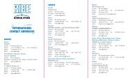
Corresponding nominal diameter d a /d1 (-)<br />
Guidelines for the sizing of direct<br />
fasteners in plastic<br />
Corresponding critical<br />
thread reach I /d1 (-) E<br />
Tensile strength σ in plastic (Mpa)<br />
Technical daTa –<br />
for PlasTic comPonenTs<br />
The starting point for correctly sizing a direct fastening in plastic is the required<br />
clamping force, which is limited by the maximum fracture force of the screw. This<br />
determines the required screw dimensions. The tables on the right show guide val-<br />
ues for each screw dimension for the required hole diameters and for the expected<br />
values of insertion and tightening torque.<br />
The stress resistance of the plastic determines the necessary thread reach. The most<br />
frequently used plastics are listed in the table below. Using the permissible stress<br />
shown in the table, the corresponding thread reach and external diameter of the<br />
screw dome can be read from the diagram. These values together with suggestions<br />
for a screw enclosure enable the screw geometry and the component fastening area<br />
to be determined rapidly. For special fastening requirements, these guide values<br />
should be checked by experiment and optimized if necessary.<br />
Permissible stresses: Guide values in plastic<br />
plastic (Mpa)<br />
ABS 50<br />
EP epoxy resin 65 –110<br />
PA6 dry – rel. humidity 3 % H 2 O 30 – 85<br />
PA6 GF30 dry – rel. humidity 3 % H 2 O 100 –170<br />
PA6 GF50 dry – rel. humidity 3 % H 2 O 120 –190<br />
PA66 dry – rel. humidity 2.5 % H 2 O 60 – 85<br />
PC 60<br />
PC GF30 80<br />
PE 30<br />
POM 65<br />
PP 30<br />
PUR 50<br />
PVC hard 65<br />
SAN 70<br />
UP 75<br />
The permissible stress is derived from the yield stress, 1 % extension stress or the fracture strength, depending on the<br />
material properties of the plastic. The values given are guide values for a quick estimate. For low-relaxation fastenings, the<br />
permissible stress should be reduced by a factor of 0.5 – 0.8.
<strong>RIBE</strong> ® PR thread dimensions<br />
<strong>Thread</strong> pR 1.8 pR 2.0 pR 2.2 pR 2.5 pR 3.0 pR 3.5 pR 4.0 pR 5.0 pR 6.0 pR 7.0<br />
a 1.30 1.40 1.50 1.70 1.90 2.10 2.40 3.00 3.60 4.20<br />
b 7.00 +1.1 8.00 +1.3 9.00 +1.4 10.00 +1.6 12.00 +1.9 14.00 +2.3 16.00 +2.7 20.00 +3.2 24.00 +3.8 28.00 +4.5<br />
d 1 (h13) 1.95 2.15 2.35 2.65 3.15 3.65 4.15 5.15 6.15 7.20<br />
d 2 (h12) 1.20 1.32 1.43 1.60 1.90 2.18 2.48 3.04 3.63 4.20<br />
d 3 1.50 1.60 1.70 1.90 2.30 2.60 3.00 3.60 4.25 4.50<br />
p 0.80 0.91 0.98 1.12 1.34 1.57 1.79 2.24 2.69 3.14<br />
x max 0.80 0.90 1.00 1.20 1.40 1.60 1.80 2.20 2.70 3.20<br />
y max 0.80 0.90 1.00 1.20 1.40 1.60 1.80 2.20 2.70 3.20<br />
PLASTOFORM thread dimensions<br />
<strong>Thread</strong> p 3.0 p 3.5 p 4.0 p 4.5 p 5.0 p 5.5 p 6.0 p 6.5<br />
a 1.30 +0.50 1.50 +0.50 1.80 +0.60 1.80 +0.70 2.20 +0.80 2.40 +0.80 2.50 +0.90 2.90 +1.00<br />
b 12.00 +1.90 14.00 +2.30 16.00 +2.70 18.00 +2.60 20.00 +3.20 22.00 +3.50 24.00 +3.80 26.00 +4.30<br />
d 1 3.00 -0.20 3.50 -0.20 4.00 -0.25 4.50 -0.25 5.00 -0.25 5.50 -0.25 6.00 -0.25 6.50 -0.25<br />
d 2 1.87 -0.20 2.03 -0.20 2.50 -0.20 2.70 -0.25 2.96 -0.25 3.35 -0.25 3.64 -0.25 3.83 -0.25<br />
p 1.27 1.53 1.78 1.84 2.15 2.35 2.54 2.87<br />
x max 1.30 1.60 1.80 1.90 2.20 2.40 2.60 2.90<br />
y max 1.30 1.60 1.80 1.90 2.20 2.40 2.60 2.90<br />
Type<br />
Nominal diameter<br />
d 1 (mm)<br />
Min. screw<br />
fracture force (kN)<br />
d B ductile plastic<br />
(mm)*<br />
d B brittle plastic<br />
(mm)*<br />
Insertion torque M E<br />
approx. (Nm)<br />
Tightening torque M A<br />
approx. (Nm)<br />
Characteristic values for PLASTOFORM and <strong>RIBE</strong> ® PR screws<br />
p 3.00 p 3.50 p 4.00 p 4.50 p 5.00 p 5.50 p 6.00 p 6.50<br />
pR 2.00 pR 2.50 pR 3.00 pR 3.50 pR 4.00 pR 5.00 pR 6.00 pR 7.00<br />
2.00 2.50 3.00 3.50 4.00 4.50 5.00 5.50 6.00 6.50 7.00<br />
0.95 1.40 1.75 2.10 3.30 3.80 4.60 6.00 7.20 8.10 9.50<br />
1.60 2.00 2.40 2.80 3.40 3.80 4.20 4.60 5.10 5.50 5.50<br />
1.80 2.10 2.60 3.00 3.60 4.00 4.50 5.00 5.40 5.90 5.90<br />
0.10 0.20 0.50 0.70 0.80 1.20 1.50 2.00 3.00 4.00 5.00<br />
0.25 0.50 1.00 1.40 1.60 2.40 3.00 4.50 6.00 8.00 10.00<br />
The values given are guide values as many parameters influence the process (e.g. materials, surfaces, geometry, assembly<br />
conditions). Optimized fastenings usually require adaptation of d B , lE and d a .<br />
* Hole tolerance +0.05 mm.<br />
<strong>RIBE</strong> ® PR<br />
PLASTOFORM<br />
(External Ø slightly<br />
less in section y)<br />
(External Ø slightly<br />
less in section y)<br />
Plastic
sPecial cases<br />
<strong>Thread</strong> locking / cleaning<br />
kleerTiTe<br />
KLEERTITE screws are TAPTITE ® screws with a special paint<br />
removal crest for “soiled” pilot holes. They are used as thread-<br />
forming screws in applications such as<br />
painted pilot holes or as fixing screws in<br />
soiled mating threads. One of the main<br />
applications for these screws is for<br />
ground connections.<br />
kleerlok<br />
KLEERLOK screws are based on the POWERLOK geometry<br />
and have a special paint removal crest for cleaning exist-<br />
ing "soiled" mating threads. This eliminates the need for ex-<br />
pensive plugging to protect the mating thread. The screw<br />
geometry also provides a metallic captive function, which<br />
allows rapid and reliable assembly under constant torque and<br />
prestressing force conditions and distinctly<br />
reduces assembly costs.<br />
sPecial cases<br />
<strong>Thread</strong> locking / cleaning<br />
<strong>RIBE</strong> ® offers special screws with a trilobular shank geometry<br />
and additional features like thread locking and thread clean-<br />
ing for use in existing metric mating threads and for cleaning<br />
“soiled” pilot holes. If metric mating threads are available,<br />
the trilobularity has a similar effect to thread forming and<br />
reduces the insertion torque under difficult assembly condi-<br />
tions, which provides additional clamping forces by reform-<br />
ing the root of the mating thread (POWERLOK). KLEERLOK<br />
screws remove existing soiling like dirt or paint when they<br />
are screwed in. This eliminates applying additional adhesive<br />
thread coatings and extra work, which can make a significant<br />
contribution to minimizing the total fastening costs.<br />
Powerlok<br />
POWERLOK screws are trilobular securing screws for existing<br />
metric mating threads. Reducing the flank angle in the area<br />
of the thread crest (60° -> 30°) and increasing the external<br />
diameter results in elastic reforming at the thread crest of<br />
the screw and at the body diameter of the mating thread<br />
during assembly. This produces the clamping effect in the<br />
thread, which is largely reversible due to the<br />
elastic nature and is therefore also suitable<br />
for repeated assembly.
Richard Bergner Verbindungstechnik GmbH & Co. KG<br />
Bahnhofstr. 8-16 · 91126 Schwabach · Germany<br />
Telephone +49 (0) 91 22 / 87-17 41 · Fax +49 (0) 91 22 / 87-15 37<br />
E-Mail Verbindungstechnik@ribe.de · Internet www.ribe.de<br />
VT/116/02/1007/2.0/pm © Richard Bergner Verbindungstechnik GmbH & Co. KG www.cmb-group.de