TankRadar Pro - Rosemount Tank Radar
TankRadar Pro - Rosemount Tank Radar
TankRadar Pro - Rosemount Tank Radar

You also want an ePaper? Increase the reach of your titles
YUMPU automatically turns print PDFs into web optimized ePapers that Google loves.
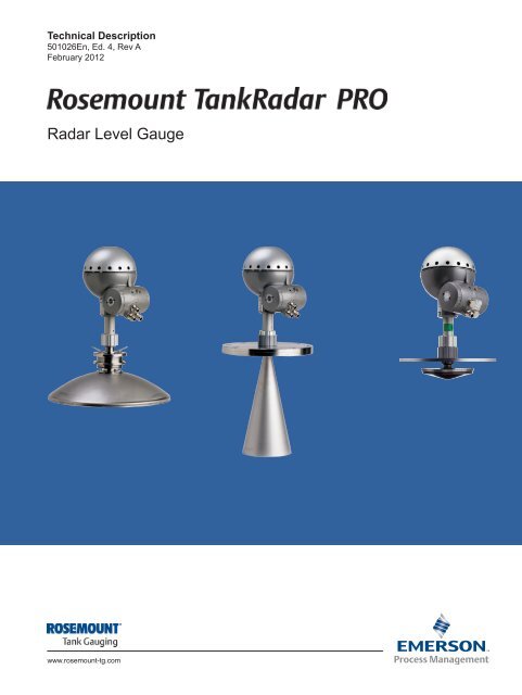
Technical Description<br />
501026En, Ed. 4, Rev A<br />
February 2012<br />
<strong>Radar</strong> Level Gauge<br />
www.rosemount-tg.com
Technical Description<br />
501026En, Ed. 4, Rev A<br />
February 2012 <strong><strong>Tank</strong><strong>Radar</strong></strong> <strong>Pro</strong><br />
Contents<br />
System overview ________________________________________________ 5<br />
Features _______________________________________________________ 6<br />
Measurement principle ___________________________________________ 6<br />
Applications ____________________________________________________ 7<br />
Select the right <strong>Pro</strong> gauge ________________________________________ 8<br />
Transmitter Head versions ________________________________________________8<br />
Software modules _______________________________________________________8<br />
Antenna versions ________________________________________________ 9<br />
Cone antenna __________________________________________________________9<br />
Parabolic antenna ______________________________________________________10<br />
Still-pipe Array antenna __________________________________________________ 11<br />
<strong>Pro</strong>cess seal antenna ___________________________________________________12<br />
Flanges _______________________________________________________ 12<br />
Measuring range _______________________________________________ 13<br />
System integration _____________________________________________ 14<br />
4-20 mA HART systems _________________________________________________14<br />
TRL2 fieldbus systems __________________________________________________15<br />
Mechanical mounting ___________________________________________ 16<br />
Free propagation _______________________________________________________16<br />
Pipe installation ________________________________________________________17<br />
Electrical connections ___________________________________________ 17<br />
Specification __________________________________________________ 18<br />
<strong>Pro</strong>duct certificates _____________________________________________ 21<br />
Ordering information ____________________________________________ 23<br />
Transmitter Head ______________________________________________________23<br />
3
<strong><strong>Tank</strong><strong>Radar</strong></strong> <strong>Pro</strong><br />
Copyright © February 2012<br />
by <strong>Rosemount</strong> <strong>Tank</strong> <strong>Radar</strong> AB.<br />
4<br />
Technical Description<br />
501026En, Ed. 4, Rev A<br />
February 2012<br />
Antennas _____________________________________________________________24<br />
Cone antenna ______________________________________________________24<br />
Cone antenna, extended _____________________________________________25<br />
Cone antenna with integrated purging ___________________________________26<br />
Parabolic antenna ___________________________________________________27<br />
Still-pipe array antenna _______________________________________________27<br />
1- and 2-in. still-pipe antennas _________________________________________28<br />
<strong>Pro</strong>cess seal antenna ________________________________________________29<br />
Model Code Example ________________________________________________29<br />
Wireless _____________________________________________________________30<br />
Smart Wireless THUM Adapter _______________________________________30<br />
Smart Wireless <strong>Tank</strong> Gauging Options ___________________________________30<br />
Technical data is subject to change without prior notice.<br />
<strong>Rosemount</strong> <strong>Tank</strong> <strong>Radar</strong> AB accepts no responsibility for any errors that may appear in<br />
this description.<br />
Viton, and Kalrez are trademarks of Du Pont Performance Elastomers.<br />
Hastelloy is a trademark of Haynes International.<br />
Monel is a trademark of International Nickel Co.<br />
HART is a trademark of the HART Communication Foundation<br />
DeltaV is a trademark of Emerson <strong>Pro</strong>cess Management group of companies.<br />
All other marks are the property of their respective owners.
Technical Description<br />
501026En, Ed. 4, Rev A<br />
February 2012 <strong><strong>Tank</strong><strong>Radar</strong></strong> <strong>Pro</strong><br />
System overview<br />
<strong>Pro</strong> Parabolic<br />
Antenna Gauge<br />
<strong>Pro</strong> Still-pipe<br />
Array<br />
Antenna Gauge<br />
<strong>Pro</strong> Cone<br />
Antenna<br />
Gauge<br />
Temperature<br />
Sensor<br />
<strong>Pro</strong> Still-pipe<br />
Antenna Gauge<br />
<strong>Pro</strong> <strong>Pro</strong>cess<br />
Seal Antenna<br />
Gauge<br />
2210 Display<br />
Unit<br />
Field<br />
Communication<br />
Unit<br />
<strong>Tank</strong>Master PC<br />
Workstations in<br />
network<br />
RTG 3900<br />
<strong><strong>Tank</strong><strong>Radar</strong></strong> Rex<br />
Field Bus<br />
Modem<br />
Alternative<br />
Connections<br />
to DCS<br />
5
<strong><strong>Tank</strong><strong>Radar</strong></strong> <strong>Pro</strong><br />
Features<br />
6<br />
• Multi-purpose radar level gauge<br />
• No moving parts and no contact with the liquid<br />
• No maintenance<br />
• Highest reliability<br />
• Easy installation<br />
• High accuracy<br />
• Handles difficult tank conditions due to<br />
ultra-high sensitivity and unique signal<br />
processing features<br />
• High flexibility with interchangeable<br />
Transmitter Heads and antennas<br />
• A wide array of antennas and versions for<br />
best performance in all applications<br />
• Interactive setup with Windows based PC<br />
software or via display unit<br />
• Analog 4-20 mA superimposed with<br />
HART , and digital <strong>Pro</strong>fibus DP, TRL2, or<br />
RS485 fieldbus outputs<br />
Measurement principle<br />
The level of the liquid (or solid) is measured by radar<br />
signals transmitted from the antenna at the tank top.<br />
After the radar signal is reflected by the liquid surface<br />
the echo is picked up by the antenna. As the signal is<br />
varying in frequency the echo has a slightly different<br />
frequency compared to the signal transmitted at that<br />
moment. The difference in frequency is proportional<br />
to the distance to the liquid, and can be accurately<br />
calculated. This method is called FMCW (Frequency<br />
Modulated Continuous Wave) and is used in all high<br />
performance radar gauges.<br />
<strong><strong>Tank</strong><strong>Radar</strong></strong> <strong>Pro</strong> uses the 10 GHz frequency band<br />
to get optimum balance between beamwidth and<br />
sensitivity to antenna contamination.<br />
Technical Description<br />
501026En, Ed. 4, Rev A<br />
February 2012<br />
<strong><strong>Tank</strong><strong>Radar</strong></strong> <strong>Pro</strong> with its flexible configuration is suitable<br />
for both stand-alone applications and large-scale plant<br />
installations with various tank types.<br />
∆ f<br />
f max<br />
f min<br />
f 1<br />
f 0<br />
Frequency (GHz)<br />
t 0<br />
∆ t<br />
The FMCW method is based on a radar<br />
sweep with continuous changes in<br />
frequency.<br />
t 1<br />
d<br />
Transmitted<br />
Reflected<br />
∆ f ~ ∆ t ~ ∆ d<br />
f 1<br />
Time<br />
f 0
Technical Description<br />
501026En, Ed. 4, Rev A<br />
February 2012 <strong><strong>Tank</strong><strong>Radar</strong></strong> <strong>Pro</strong><br />
Applications<br />
<strong><strong>Tank</strong><strong>Radar</strong></strong> <strong>Pro</strong> uses state-of-the art microwave<br />
technology to get highest reliability and precision.<br />
It measures the level of liquids, slurries as well as<br />
many solids. The gauge operates in a wide range<br />
of temperatures, pressures, vapor gas mixtures and<br />
various process conditions.<br />
The applications include:<br />
• Storage tanks at refineries and tank terminals<br />
• LPG storage<br />
• Power plants<br />
• Chemical & petrochemical industry<br />
• Pharmaceutical<br />
• Food and beverage<br />
• Water and sewage treatment<br />
• Hydroelectric power generation and dams<br />
• Cement, powder, wood chips and other solid<br />
material applications<br />
Still-pipe or bridle mounting is recommended for LPG<br />
applications, where the surface sometimes is boiling, and for<br />
some extremely turbulent conditions. The pipe reduces foam<br />
and turbulence and also increases surface reflection.<br />
<strong><strong>Tank</strong><strong>Radar</strong></strong> <strong>Pro</strong> parabola and cone versions provide free<br />
propagation, high accuracy level measurement in storage<br />
tanks.<br />
Solid materials, like cement, often give extremely small radar<br />
reflections, requiring the most sensitive antenna, the 20”<br />
parabolic.<br />
Applications in tanks with agitators require a radar gauge<br />
with <strong><strong>Tank</strong><strong>Radar</strong></strong> <strong>Pro</strong>’s high sensitivity and advanced signal<br />
processing to separate the measuring signal from noise<br />
created by disturbances.<br />
7
<strong><strong>Tank</strong><strong>Radar</strong></strong> <strong>Pro</strong><br />
Select the right <strong>Pro</strong> gauge<br />
A <strong><strong>Tank</strong><strong>Radar</strong></strong> <strong>Pro</strong> gauge consists of a Transmitter<br />
Head and a tank connection including antenna.<br />
The Transmitter Head, as well as the electronics<br />
inside, is interchangeable without opening the tank.<br />
Transmitter Head versions<br />
The Transmitter Head is available in four basic<br />
versions:<br />
8<br />
• Lite<br />
Intended for applications in non-hazardous areas<br />
only. Suitable for tanks without internal structures and<br />
agitators, e.g. certain storage tanks, water, dam<br />
applications etc. The Lite version has FFT calculations<br />
enabled providing an instrument accuracy of<br />
± 10 mm (± 0.4 in.). Echofixer, FHAST and MET<br />
are available as options.<br />
• Standard<br />
For hazardous applications in most tanks (also spheri-<br />
cal or bullet tanks, and tanks with internal structures).<br />
The Standard version includes the Echofixer software<br />
which more accurately than standard FFT maps all<br />
microwave interference sources. The Standard<br />
instrument accuracy is ± 10 mm (± 0.4 in.) which can<br />
be improved to ± 5 mm (± 0.2 in.) using the optional<br />
FHAST software module.<br />
• Gold<br />
Gold is the most advanced version for difficult<br />
applications in tanks with agitators, heating coils and<br />
other disturbances. It includes the Echofixer software,<br />
FHAST software for increased accuracy plus MET<br />
software for further increased disturbance echo<br />
handling. Instrument accuracy is ± 5 mm (± 0.2 in.).<br />
• Platinum<br />
For high accuracy tank gauging applications, Platinum<br />
is the best <strong><strong>Tank</strong><strong>Radar</strong></strong> <strong>Pro</strong> choice. It includes the<br />
FHAST software and selected hardware for<br />
maximum performance. Instrument accuracy is<br />
± 3 mm (± 0.12 in.) for parabolic, still-pipe array and<br />
8-in. cone antennas.<br />
Volume calculation for symmetrical tanks is included<br />
in all versions. Strapping table for non-symmetrical<br />
tanks is available as an option.<br />
Software modules in available <strong>Pro</strong> versions<br />
Explosion<br />
approval<br />
FFT FHAST<br />
Increased<br />
accuracy<br />
Echofixer<br />
Disturbance<br />
echo handling<br />
MET<br />
Improved<br />
resolution<br />
Lite - X Option Option Option<br />
Standard X X Option X Option<br />
Gold X X X X X<br />
Platinum X X X Option -<br />
Weather protection<br />
Electronic housing<br />
Display unit<br />
Junction box Ex (e)<br />
Cable glands<br />
Junction box Ex (i)<br />
Antenna<br />
<strong>Tank</strong> connection<br />
Software modules<br />
Technical Description<br />
501026En, Ed. 4, Rev A<br />
February 2012<br />
Various options make it possible to optimize the<br />
gauge for different applications:<br />
• Fast Fourier Transformation (FFT)<br />
Fast Fourier Transformation is a signal processing<br />
technique used to map the echo structure of the tank.<br />
• Echofixer<br />
A software module that makes it possible to measure on<br />
the surface in spite of strong disturbance echoes from<br />
mechanical structures such as agitators and baffles.<br />
• Fast High Accuracy Signal Technology (FHAST)<br />
A module that improves the efficiency of the signal<br />
processing by limiting the region to be analyzed around<br />
the surface. This results in an improved accuracy of<br />
± 5 mm (± 0.2 in.).<br />
• Multiple Echo Tracking (MET)<br />
Improves the resolution and accuracy in echo disturbed<br />
regions and close to the tank bottom. Continuous<br />
measurement on multiple disturbing echoes facilitates<br />
identification of the actual surface echo.<br />
All software options are possible to upgrade in the<br />
field without any changes in electronics. Upgrades<br />
are made by entering a new start code in the gauge<br />
and can be done on a temporary basis for trial<br />
purposes.
Technical Description<br />
501026En, Ed. 4, Rev A<br />
February 2012 <strong><strong>Tank</strong><strong>Radar</strong></strong> <strong>Pro</strong><br />
Antenna versions<br />
<strong><strong>Tank</strong><strong>Radar</strong></strong> <strong>Pro</strong> can be equipped with different<br />
antennas to fulfill various requirements. The tank<br />
connection, including antenna, is the only part<br />
exposed to the tank atmosphere. The cone antenna<br />
is most commonly used. When selecting antenna<br />
dimension, it is generally recommended to use as<br />
large antenna diameter as possible.<br />
Cone antenna<br />
The cone antenna is suitable for liquid applications.<br />
It can be used for both free propagation and still-pipe<br />
mounted installations. Thanks to the unique flange<br />
clamp solution the existing tank flange can be used<br />
as tank connection. The gauge can also be delivered<br />
with flange included.<br />
• Standard cone antennas for 3-, 4-, 6- and 8-in. tank<br />
openings. The 3-, 4- and 6-in. cones can be extended<br />
to fit long tank nozzles. See pages 23-30, “Ordering<br />
Information”, for standard flange options<br />
• A 1- and 2-in. version is available together with a<br />
still-pipe solution<br />
• For larger pipes, use the still-pipe array antennas<br />
• Materials exposed to the tank atmosphere:<br />
Sealing in PTFE or quartz<br />
Antenna in stainless steel, Hastelloy C-22<br />
Titanium gr. 2, Monel 400 or Tantalum<br />
O-ring in Viton fluoroelastomer or Kalrez<br />
perfluoroelastomer<br />
• Accuracy up to ± 5 mm (± 0.2 in.) using the FHAST<br />
software option<br />
• Accuracy with 8-in. cone up to ± 3 mm (± 0.12 in.)<br />
using the Platinum version<br />
See page 17 for description of still-pipe installations.<br />
For pressure and temperature restrictions depending<br />
on flange and O-ring selection, see page 20.<br />
mm (inches)<br />
2 in. : 56 (2.20)<br />
3 in. : 70 (2.76)<br />
4 in. : 93 (3.66)<br />
6 in. : 141 (5.55)<br />
8 in. : 189 (7.44)<br />
Pressure (bar)<br />
200 (7.87)<br />
60<br />
55<br />
50<br />
40<br />
30<br />
20<br />
10<br />
5<br />
0<br />
-1<br />
-40 32 212 392 570<br />
1<br />
2<br />
400<br />
(15.75)<br />
The thin antenna plate prevents the<br />
flange from exposure to the tank<br />
environment.<br />
2 in. : 70 (2.76)<br />
3 in. : 95 (3.74)<br />
4 in. : 150 (5.91)<br />
6 in. : 260 (10.24)<br />
8 in. : 370 (14.57)<br />
Temperature (°F)<br />
1<br />
2<br />
Quartz<br />
PTFE<br />
-40 0 100 200 300<br />
Temperature (°C)<br />
2-in. Still-pipe Antenna<br />
752<br />
400<br />
798<br />
145<br />
73<br />
0<br />
-15<br />
Pressure (psig)<br />
The relation between temperature and maximum pressure<br />
for cone antennas.<br />
9
<strong><strong>Tank</strong><strong>Radar</strong></strong> <strong>Pro</strong><br />
Parabolic antenna<br />
The parabolic antenna is suitable for both liquid and<br />
solid applications. As it has the largest diameter it<br />
has the most narrow radar beam and can be used<br />
for extremely long measuring distances.<br />
The parabolic is also the antenna type most<br />
insensitive to contamination. It can be used in<br />
applications with severe antenna condensation like<br />
asphalt and liquid sulphur.<br />
Two versions are available:<br />
the very easily installed version with clamped<br />
mounting of flanges with a 96 mm (3.78-in.) diameter<br />
hole in flange (low pressures) and a welded version<br />
(high pressures).<br />
10<br />
• Suitable in all tanks with 450 mm (18 in.)<br />
or larger openings<br />
• Exposed parts in tank: Stainless steel<br />
and FEP/PTFE fluoropolymer<br />
• Best installed accuracy for inventory<br />
applications<br />
• Highest antenna gain<br />
• Withstands heavy contamination<br />
• Flexible PTFE protective cover available for<br />
dusty applications<br />
• Suitable for long range measurement up<br />
to 100 m (330 ft)<br />
• ± 3 mm (± 0.1 in.) accuracy for platinum version<br />
Parabolic antenna welded to tank opening.<br />
mm (inches)<br />
Pressure (bar)<br />
10<br />
0.5<br />
+0.2<br />
0<br />
-0.2<br />
0.5<br />
-40<br />
-40<br />
32<br />
0<br />
Technical Description<br />
501026En, Ed. 4, Rev A<br />
February 2012<br />
122 212 302<br />
50 100 150<br />
Temperature (°C)<br />
392 445<br />
200 230<br />
145<br />
5 73<br />
1<br />
1<br />
2<br />
200 (7.87)<br />
445 (17.52)<br />
Temperature (°F)<br />
1<br />
2<br />
Welded<br />
Clamped<br />
+2.9<br />
0<br />
-2.9<br />
440<br />
(17.32)<br />
162<br />
(6.4)<br />
The relation between temperature and maximum pressure for<br />
parabolic antennas.<br />
Pressure (psig)
Technical Description<br />
501026En, Ed. 4, Rev A<br />
February 2012 <strong><strong>Tank</strong><strong>Radar</strong></strong> <strong>Pro</strong><br />
Still-pipe Array antenna<br />
The Still-pipe Array Antenna with its small-sized<br />
antenna is designed for mounting on existing stillpipes.<br />
Typical applications are crude oil tanks with<br />
floating roofs and gasoline/product tanks with or<br />
without inner floating roofs.<br />
The gauge uses a unique patented Low Loss Mode<br />
to transmit the radar waves in the center of the pipe.<br />
This virtually eliminates degradation of the accuracy<br />
due to rust and product deposits inside the pipe.<br />
The Still-pipe Array Antenna is available in two<br />
models, the fixed and the hinged-lid version.<br />
The still-pipe must be vertical within 0.5° (0.2 m over<br />
20 m) to obtain highest measurement accuracy.<br />
Pressure (bar)<br />
• Suitable for mounting on existing still-pipes<br />
• Small-sized antenna for 5-, 6-, 8-, 10- or 12-in.<br />
still-pipes<br />
• Exposed parts in tank:<br />
Antenna in Polyphenylensulfid (PPS)<br />
Sealing in PTFE<br />
O-ring in Fluorosilicone<br />
Flange in Acid <strong>Pro</strong>of Steel EN 1.4404<br />
(AISI 316L)<br />
• ± 3 mm (± 0.1 in.) accuracy<br />
2.00<br />
1.75<br />
1.50<br />
1.25<br />
1.00<br />
0.75<br />
0.50<br />
-40<br />
3<br />
2<br />
Temperature (°F)<br />
32 68 104 140 176 212 248<br />
1<br />
2<br />
3<br />
Hinged Hatch 10 & 12 in.<br />
14.5<br />
7.2<br />
0.25<br />
3.6<br />
0<br />
1<br />
0<br />
-40 0 20 40 60 80 100 120<br />
Temperature (°C)<br />
Hinged Hatch 5,6 and 8 in.<br />
Fixed<br />
The relation between temperature and maximum pressure for<br />
array antennas.<br />
29<br />
Pressure (psig)<br />
<strong>Pro</strong> Still-pipe Array Antenna,<br />
fixed version.<br />
mm (inches)<br />
200 (7.87)<br />
<strong>Pro</strong> Still-pipe Array Antenna,<br />
hinged-lid version with<br />
design that enables handdipping.<br />
400<br />
(15.75)<br />
11
<strong><strong>Tank</strong><strong>Radar</strong></strong> <strong>Pro</strong><br />
<strong>Pro</strong>cess seal antenna<br />
The dish made of PTFE or ceramics seals off the<br />
cone shaped antenna from the tank atmosphere.<br />
This combines the benefits of using a cone antenna<br />
with the advantage of only exposing material<br />
suitable for hygienic or corrosive applications.<br />
12<br />
• Suitable in hygienic or aggressive tank<br />
atmospheres<br />
• Cone antenna protected from the tank<br />
atmosphere by a ceramic or PTFE sealing<br />
• Ceramic seal withstands high pressures and<br />
temperatures<br />
• 4- and 6-in. versions<br />
• 4-in. version for hazardous applications<br />
• ± 10 mm (± 0.4 in.) accuracy<br />
Pressure (bar)<br />
20<br />
0<br />
-1<br />
-40 32 212 392 570<br />
-40 0 100 150 200 300<br />
Temperature (°C)<br />
752<br />
1<br />
16 230<br />
15<br />
1 4-in. Ceramic<br />
10<br />
2<br />
3<br />
4<br />
Temperature (°F)<br />
6-in. Ceramic<br />
4-in. PTFE<br />
6-in. PTFE<br />
2<br />
6 86<br />
5<br />
3<br />
4<br />
2<br />
400<br />
The relation between temperature and maximum pressure for<br />
process seal antennas.<br />
0<br />
-15<br />
Pressure (psig)<br />
mm (inches)<br />
Flanges<br />
200 (7.87)<br />
4 in. : 160 (6.30)<br />
6 in. : 218 (8.58)<br />
Technical Description<br />
501026En, Ed. 4, Rev A<br />
February 2012<br />
4 in. : 550 (21.65)<br />
6 in. : 650 (25.59)<br />
Flanges are available in DIN, ANSI or JIS standards.<br />
Flange material is hot-dipped galvanized carbon<br />
steel or stainless steel.<br />
For complete listing of available standard flanges,<br />
see page 18 “Specification” and pages 23-30<br />
“Ordering Information”.<br />
NOTE: Pressure rating for the different antennas may be<br />
lower depending on flange selection. Minimum / maximum<br />
flange temperature depends on O-ring selection.
Technical Description<br />
501026En, Ed. 4, Rev A<br />
February 2012 <strong><strong>Tank</strong><strong>Radar</strong></strong> <strong>Pro</strong><br />
Measuring range<br />
The diagrams below show how the measuring<br />
range is influenced by the antenna type, dielectric<br />
constant of the liquid (ε r ) and the process conditions.<br />
For optimum performance the maximum measuring<br />
distance should be kept within the range indicated<br />
with darker colour in the diagrams. To increase the<br />
measuring range further in turbulent tanks, a stillpipe<br />
can be used.<br />
a: Oil, petrochemicals, gasoline and other<br />
hydrocarbons (ε r =1.9-4.0).<br />
b: Alcohols, concentrated acids, organic<br />
solvents, oil/water mixtures and acetone<br />
(ε r =4.0-10).<br />
c: Conductive liquids, e.g. water based<br />
solutions, dilute acids and alkalis (ε r > 10).<br />
(m)<br />
(m)<br />
(m)<br />
0<br />
10<br />
20<br />
30<br />
40<br />
50<br />
60<br />
a b c a b c a b c a b c a b c<br />
0<br />
0<br />
0<br />
0<br />
10<br />
20<br />
30<br />
40<br />
50<br />
60<br />
10<br />
20<br />
30<br />
40<br />
50<br />
60<br />
3-in. Cone 4-in. Cone 6-in. Cone 8-in. Cone Parabolic<br />
0<br />
a b c<br />
0<br />
a b c<br />
0<br />
a b c<br />
0<br />
a b c<br />
0<br />
a b c<br />
10<br />
20<br />
30<br />
40<br />
50<br />
0<br />
10<br />
20<br />
30<br />
40<br />
50<br />
3-in. Cone 4-in. Cone 6-in. Cone 8-in. Cone Parabolic<br />
5-, 6- and 8-in.<br />
Array Antenna<br />
10<br />
20<br />
30<br />
40<br />
50<br />
10<br />
20<br />
30<br />
40<br />
50<br />
a b c a b c a b c a b c a b c<br />
0<br />
0<br />
0<br />
0<br />
10<br />
20<br />
30<br />
40<br />
50<br />
10-12-in.<br />
Array Antenna<br />
10<br />
20<br />
30<br />
40<br />
50<br />
1-in. Still-pipe<br />
Antenna<br />
For still-pipe mounted <strong>Pro</strong> gauges the typical<br />
measuring range is 35-50 m (115-160 ft) also in<br />
turbulent tanks with liquids having ε r less than 1.9.<br />
NOTE:<br />
• For liquids with ε r smaller than 1.9, such as liquefied<br />
gas, an 8-in. or bigger antenna is recommended for<br />
free propagation measurements. In this case, the typical<br />
measuring range is 15 m (50 ft).<br />
• The measuring range for 4- and 6-in. process seal<br />
antennas equals about 60% of that for 4- and 6-in.<br />
cone antennas.<br />
• For array antennas, the measuring range depends on<br />
still-pipe slot size.<br />
• The values below are valid for clean antennas.<br />
• Max. product level should be kept 20 mm (0.8 in.) from the<br />
antenna end.<br />
10<br />
20<br />
30<br />
40<br />
50<br />
60<br />
10<br />
20<br />
30<br />
40<br />
50<br />
10<br />
20<br />
30<br />
40<br />
50<br />
2-in. Still-pipe<br />
Antenna<br />
10<br />
20<br />
30<br />
40<br />
50<br />
60<br />
10<br />
20<br />
30<br />
40<br />
50<br />
10<br />
20<br />
30<br />
40<br />
50<br />
3-6-in. Cone Antenna in<br />
existing still-pipe<br />
Measuring range<br />
in tanks with calm<br />
surfaces.<br />
Measuring range<br />
in gently stirred<br />
tanks.<br />
Measuring range in<br />
still-pipe tanks.<br />
13
<strong><strong>Tank</strong><strong>Radar</strong></strong> <strong>Pro</strong><br />
System integration<br />
<strong><strong>Tank</strong><strong>Radar</strong></strong> <strong>Pro</strong> can be equipped with a number of<br />
different output alternatives such as<br />
4-20 mA HART, <strong>Pro</strong>fibus DP, the <strong>Rosemount</strong><br />
Modbus based TRL2 field bus or RS485. Any or<br />
multiple of the calculated values such as level,<br />
volume, average temperature or signal strength can<br />
be assigned to the signal output.<br />
Data are displayed on the optional 2210 Display<br />
Unit mounted on the gauge or separately. Via the<br />
remotely mounted display, up to six temperature<br />
sensors can be connected.<br />
<strong><strong>Tank</strong><strong>Radar</strong></strong> <strong>Pro</strong> is easily configurable on the 4-key<br />
display keyboard or via a PC using the windows<br />
based <strong>Tank</strong>Master Winsetup software package.<br />
4-20 mA HART systems<br />
The 4-20 mA HART analog outputs are either<br />
passive for connection to powered cables or active<br />
providing signal power for external display units<br />
etc. The analog outputs can also be specified to be<br />
intrinsically safe. Configuration can also be done<br />
from a <strong>Rosemount</strong> AMS system or a 375/475<br />
Handheld Communicator.<br />
14<br />
4-20 mA/HART<br />
Temperature<br />
sensor<br />
Remote<br />
display<br />
Alarm<br />
Relay<br />
Unit<br />
Handheld Communicator<br />
Modem<br />
Technical Description<br />
501026En, Ed. 4, Rev A<br />
February 2012<br />
The intrinsically safe 2210 Display Unit shows level<br />
(m or ft) and temperature (ºC or ºF), and it can be used<br />
for gauge configuration.<br />
Control System<br />
PC with <strong>Tank</strong>Master software
Technical Description<br />
501026En, Ed. 4, Rev A<br />
February 2012 <strong><strong>Tank</strong><strong>Radar</strong></strong> <strong>Pro</strong><br />
TRL2 fieldbus systems<br />
When using the digital TRL2 field bus outputs, up<br />
to 12-15 gauges can be connected to each twowire<br />
field bus, maintaining a high data updating<br />
speed. Each field bus is connected to a Field<br />
Communication Unit (FCU) that handles up to four<br />
field buses with data from maximum 32 tanks.<br />
Several FCU's can be installed to handle a large<br />
number of tanks. From the FCU, data can be<br />
transmitted on RS232/485 or TRL2 bus formats to<br />
host computers (DCS, PC or PLC). <strong>Pro</strong> gauges<br />
with TRL2 bus output can also be connected to the<br />
<strong>Tank</strong>Master operator software providing an OPC<br />
server that can be linked to the plant network.<br />
PC with <strong>Tank</strong>Master<br />
software<br />
Safe Area<br />
Hazardous Area<br />
Temperature<br />
Input<br />
Group<br />
Buses<br />
<strong><strong>Tank</strong><strong>Radar</strong></strong> Rex<br />
Field<br />
Communication<br />
Unit<br />
Field<br />
Buses<br />
<strong><strong>Tank</strong><strong>Radar</strong></strong> <strong>Pro</strong><br />
Display<br />
Unit<br />
Temperauture<br />
Sensor<br />
15
<strong><strong>Tank</strong><strong>Radar</strong></strong> <strong>Pro</strong><br />
Mechanical mounting<br />
The <strong><strong>Tank</strong><strong>Radar</strong></strong> <strong>Pro</strong> gauge is easily carried to the<br />
tank top and mounted on a suitable nozzle or pipe.<br />
Free propagation<br />
The gauge should be installed as follows:<br />
16<br />
• Antenna oriented perpendicular to a horizontal<br />
surface<br />
• The gauge should be mounted with as few<br />
disturbing objects as possible within the beam<br />
angle<br />
• Filling inlets creating turbulence should<br />
preferably be kept at a distance<br />
• Choose as large antenna diameter as possible.<br />
A larger receiving area concentrates the radar<br />
beam and ensures maximum antenna gain.<br />
Increased antenna gain means greater margin<br />
for weak surface echoes<br />
• The cone antenna may be inclined 1-2°<br />
towards the center of the tank to increase the<br />
accuracy (applicable for tanks higher than<br />
10 m)<br />
Beam Diameter and Beam Angle<br />
Distance, m (ft)<br />
Antenna<br />
type<br />
Beam<br />
angle<br />
3-in. Cone 4-in. Cone /<br />
4-in. <strong>Pro</strong>cess<br />
Seal<br />
6-in. Cone /<br />
6-in. <strong>Pro</strong>cess<br />
Seal<br />
8-in. Cone Parabolic<br />
25° 21° 18° 15° 10°<br />
5 (16) 2.2 (7.2) 1.9 (6.2) 1.6 (5.2) 1.3 (4.3) 0.9 (3.0)<br />
10 (33) 4.4 (14) 3.7 (12) 3.1 (10) 2.6 (8.5) 1.7 (5.6)<br />
15 (49) 6.7 (22) 5.6 (18) 4.7 (15) 3.9 (13) 2.6 (8.5)<br />
20 (66) 8.9 (29) 7.4 (24) 6.3 (21) 5.3 (17) 3.5 (11)<br />
The flat tank wall can be located within the antenna<br />
beam angle, as long as there is a minimum distance<br />
from the gauge to the tank wall, see picture above.<br />
An extended cone (picture on the right) can be used<br />
for long nozzles.<br />
The standard length of the extended cone is<br />
500 mm (20 in.) for 3-, 4- or 6-in. cone antennas.<br />
Longer cones are available on request.<br />
Distance<br />
5m<br />
10m<br />
15m<br />
20m<br />
10 mm (0.4 in.)<br />
or more<br />
Half power<br />
beam width<br />
Minimum distance:<br />
0.6 m (2.0 ft)<br />
For best measurement<br />
performance the nozzle height<br />
should be shorter than the<br />
antenna.<br />
Technical Description<br />
501026En, Ed. 4, Rev A<br />
February 2012<br />
Beam angle<br />
Beam Diameter and Beam Angle for <strong><strong>Tank</strong><strong>Radar</strong></strong> <strong>Pro</strong> antennas.<br />
Cone Antenna Extension<br />
Best practice for<br />
mechanical mounting<br />
of free propagation<br />
radar level gauge.
Technical Description<br />
501026En, Ed. 4, Rev A<br />
February 2012 <strong><strong>Tank</strong><strong>Radar</strong></strong> <strong>Pro</strong><br />
Pipe installation<br />
Still-pipe installation is particularly suitable for<br />
applications with highly turbulent liquids or liquids<br />
with very low ε r giving weak radar reflections, such<br />
as LPG. 2-, 3-, 4- and 6-in cone antennas can be<br />
mounted in existing still-pipes.<br />
Used pipes must generally be clean inside, without<br />
irregularities, rust or excessive holes.<br />
Also available is a 1-in. still-pipe and antenna<br />
assembly with a maximum range of 3 m (10 ft).<br />
The 1- and 2-in. still-pipe gauges are suitable for<br />
clean liquids only and can be delivered complete<br />
with still-pipe, deflection plate and fittings without<br />
any need for welding.<br />
It is also possible to use the Still-pipe Array antenna<br />
for measurement inside an existing still-pipe.<br />
This antenna is available in 6-, 8-, 10- and 12-in.,<br />
fixed and hinged-hatch designs.<br />
Consult Emerson <strong>Pro</strong>cess Management /<br />
<strong>Rosemount</strong> <strong>Tank</strong> Gauging or an authorized<br />
distributor for installation advice.<br />
Electrical connections<br />
The Transmitter Head has two separate junction<br />
boxes. One is for a non-intrinsically safe primary<br />
signal output and power supply cables. The other is<br />
normally used for intrinsically safe (IS) HART/analog<br />
outputs or optionally for a non-IS analog output.<br />
Non Intrinsically Safe (EEx e)<br />
Primary<br />
output<br />
4-20 mA HART+ /<strong>Pro</strong>fibus DP/TRL2 bus<br />
4-20 mA HART- /<strong>Pro</strong>fibus DP/TRL2 bus<br />
N/L1/+<br />
Power supply L/L2/-<br />
Outputs can be either active or passive depending<br />
on required options.<br />
Cables are twisted and shielded pairs, minimum<br />
0.5 mm 2 (AWG 20), ½-in. NPT (threaded) for cable<br />
glands or male conduit fittings.<br />
For complete installation instructions,<br />
see the Reference Manual for <strong><strong>Tank</strong><strong>Radar</strong></strong> <strong>Pro</strong><br />
(306010E).<br />
1<br />
2<br />
3<br />
4<br />
X1<br />
Alternative 1<br />
Intrinsically Safe (EEx i)<br />
7<br />
6<br />
5<br />
4<br />
3<br />
2<br />
1<br />
X2<br />
4<br />
3<br />
2<br />
1<br />
X2<br />
IS Gnd<br />
DP DB<br />
DP DA<br />
DP+<br />
4-20 mA-<br />
4-20 mA+<br />
4-20 mA HART-<br />
4-20 mA HART+<br />
Alternative 2<br />
Non Intrinsically Safe (EEx e)<br />
4-20 mA-<br />
4-20 mA+<br />
Deflection plate<br />
<strong><strong>Tank</strong><strong>Radar</strong></strong> <strong>Pro</strong> measures level in 1- to 12-in. still-pipes.<br />
Not used<br />
Display Panel<br />
Secondary<br />
output<br />
Primary<br />
output<br />
Secondary<br />
output<br />
17
<strong><strong>Tank</strong><strong>Radar</strong></strong> <strong>Pro</strong><br />
Specification<br />
18<br />
General<br />
<strong>Pro</strong>duct designation <strong><strong>Tank</strong><strong>Radar</strong></strong> <strong>Pro</strong>: Lite, Standard, Gold or Platinum<br />
Operating principle 10 GHz FMCW radar<br />
Beam angle See page 16<br />
Internal calibration Integrated digital reference for automatic compensation of radar sweep<br />
Signal processing Digital signal processing using FFT, FHAST, MET and Echofixer<br />
Temperature measurement 1-3 spot elements, PT100 or CU100, or 6 spot elements with common return.<br />
Input accuracy ± 0.5 °C ( ± 0.9 °F)<br />
Display / Configuration<br />
Technical Description<br />
501026En, Ed. 4, Rev A<br />
February 2012<br />
Display (factory mounted on gauge) • 6-digit graphical LCD display, 128 x 64 pixels<br />
• For display and configuration<br />
• 4 control soft-keys<br />
• 7 text lines with 16 characters/line<br />
• Weather/dirt protection cover. <strong>Pro</strong>tection class IP67<br />
Display (mounted separately) Same as above, mounted in separate enclosure, <strong>Pro</strong>tection class IP67<br />
Max cable length, display - radar gauge: 100 m (330 ft)<br />
Cable type: 4 wire shielded instrument cable, min 0.5 mm², (AWG 20)<br />
Optional: Temperature measurement 1-3 spot elements PT100 or CU100 (see above)<br />
HART device 375/475 handheld communicator<br />
<strong>Rosemount</strong> Asset Management Solutions software (AMS)<br />
PC/remote configuration <strong>Tank</strong>Master WinSetup software<br />
Mechanical<br />
Antennas Cone, Parabolic, Still-pipe Array, and <strong>Pro</strong>cess Seal antennas<br />
Antenna material exposed to tank<br />
atmosphere<br />
Cone Antenna<br />
(PTFE sealing)<br />
Cone Antenna<br />
(Quartz sealing)<br />
Antenna Material, alt 1: Stainless Steel 316L, alt 2:<br />
Hastelloy C-22, alt 3: Tantalum, alt 4: Monel 400<br />
O-rings: Viton fluoroelastomer or Kalrez perfluoroelastomer<br />
Sealing: PTFE fluoropolymer<br />
Antenna Material, alt 1: Stainless Steel 316L, alt 2:<br />
Hastelloy C-22, alt 3: Tantalum, alt 4: Monel 400<br />
O-rings: Viton fluoroelastomer or Kalrez perfluoroelastomer<br />
Sealing: Quartz<br />
Parabolic Antenna Stainless Steel 316L, FEP/PTFE fluoropolymer<br />
<strong>Pro</strong>cess Seal Antenna PTFE fluoropolymer or Al 2 O 3 (Aluminium oxide)<br />
1- and 2 in. Still-pipe<br />
Antennas<br />
Antenna Material: Stainless Steel 316L<br />
O-rings: Viton fluoroelastomer or Kalrez perfluoroelastomer<br />
Sealing: PTFE fluoropolymer or Quartz<br />
Still-pipe Array Antenna Antenna Material: Polyphenylensulfid (PPS)<br />
O-ring: Fluorosilicone<br />
Sealing: PTFE fluoropolymer<br />
Antenna dimensions See pages 9-12<br />
Antenna extension Dimensions See page 16<br />
Material Extended cone antennas available in Stainless steel 316L<br />
Flushing connection 1/2-in. NPT<br />
Housing/enclosure Permanent mould cast aluminium, chromed and 120 μm powder painted<br />
Flanges DIN, ANSI and JIS standard,<br />
Material: Stainless Steel A182 Gr. F 316L and EN 10222-5-1.4404<br />
Weight, excl. flange Approximately 8 kg (18 lbs), depending on antenna selection<br />
Height above flange 400 mm (15 in.)
Technical Description<br />
501026En, Ed. 4, Rev A<br />
February 2012 <strong><strong>Tank</strong><strong>Radar</strong></strong> <strong>Pro</strong><br />
Electrical<br />
Power supply Ultra-wide 24–240 V DC or AC 0-60 Hz<br />
Power consumption Maximum 10 W, nominal 5 W<br />
Outputs Primary output<br />
(for level, volume etc)<br />
Secondary output (Optional, for volume,<br />
signal quality, temperature etc.)<br />
Alt. 1: HART + 4–20 mA current loop (IS option)<br />
Alt. 2: TRL2 Bus (FSK with Modbus protocol)<br />
Alt. 3: <strong>Pro</strong>fibus DP<br />
Analog 4–20 mA current loop, active or passive.<br />
Optional: IS version.<br />
Analog output characteristics Type Analog 4–20 mA Current Loop, active (with) or<br />
passive (without loop supply).<br />
Galvanic isolation > 1500 V RMS or DC<br />
Accuracy ± 300 µA at 4 mA<br />
± 600 µA at 20 mA<br />
Range 4-20 mA<br />
Alarm level 3.8 mA, 22 mA or freeze; software selectable<br />
Resolution 0.5 µA (0.003%)<br />
Linearity ± 0.01%<br />
Temperature drift ± 50 ppm/°C (± 28 ppm/°F)<br />
Output impedance > 10 MΩ<br />
Voltage compliance 7-30 V (passive output)<br />
External loop resistance < 700 Ω (passive output with 24 V external supply)<br />
< 300 Ω (active output)<br />
Output cabling Twisted and shielded pair, min. 0.5 mm² (AWG 20)<br />
Cable entries 3 x ½-in. NPT, for cable glands or conduit entries.<br />
Optional: Cable gland kit, including 3 x EEx e approved (ATEX) ½-in. NPT cable glands.<br />
Optional: 3 x EEx e approved, including 3 x EEx e (ATEX) adapters ½-in. NPT/M20<br />
Relay output Optional equipment, mounted in separate enclosure. Potential free contacts, normally open or<br />
normally closed, selectable. Switching capacity: 100-260 VAC 3 A or 24-48 VDC 3 A<br />
Function: alarm limits and hysteresis set at radar gauge.<br />
19
<strong><strong>Tank</strong><strong>Radar</strong></strong> <strong>Pro</strong><br />
20<br />
Measuring performance<br />
NOTE: Pressure rating for the different antennas may be<br />
lower depending on flange selection. Minimum / maximum<br />
flange temperature depends on O-ring selection according to<br />
the table below.<br />
O-rings<br />
<strong>Pro</strong>cess<br />
temperature<br />
measured here<br />
Technical Description<br />
501026En, Ed. 4, Rev A<br />
February 2012<br />
Instrument accuracy ± 3 mm (± 0.12 in.), ± 5 mm (± 0.2 in.) or ± 10 mm (± 0.4 in.) depending on model<br />
Resolution 1 mm (0.04 in.)<br />
Temperature stability ± 500 ppm of measured distance within the ambient temperature range<br />
Repeatability ± 1 mm (± 0.04 in.)<br />
Measuring range 0-50 m (0-165 ft) default, 0-99 m (0-325 ft) special configuration<br />
Update time 100 ms<br />
Optional disturbance echo handling Echofixer and MET Multiple Echo Tracking<br />
Ex approval transmitter head<br />
(Standard, Gold and Platinum<br />
versions)<br />
See pages 21-22<br />
Overfill prevention TÜV approval, BPG-US 99/6001<br />
Environment<br />
Pressure/temperature at antenna See diagrams on pages 9-12<br />
Ambient temperature -40 ºC to 70 ºC (-40 ºF to 158 ºF)<br />
<strong>Tank</strong> temperature -40 ºC to 400 ºC (-40 ºF to 752 ºF)<br />
Pressure See pages 9-12<br />
Emission approvals FCC: K8CPRO, K8CPROX. R&TTE: E813268O-CC<br />
Humidity IEC 60068-2-3<br />
Climatic class/corrosion class IEC 68-2-1, IEC 60068-2-52 test KB severity 2<br />
Ingress protection IP65, IP66, NEMA 4<br />
Vibration IEC 721-3-4 class 4M4<br />
UV protection ISO 4892-2<br />
Electromagnetic compatibility EN61326-1:2006 incl. A1:1998 and A2:2001, Immunity EN50081-2, Emission EN50081-1<br />
Lightning protection EN61326, EN61000-4-5, IEC801-5, level 2 kV<br />
Power supply fluctuation IEC 92 Part 504 sec 3.5<br />
Boiler Approval CSA B51-97: Compliance<br />
CE-mark 93/68/EEC: complies with applicable EU directives (EMC, ATEX, LVD, and R&TTE).<br />
Based on the low emitted effects from the gauges (well below 0.1 mW) compared to limits<br />
given by the Rec. 1999/519/EC, no additional measures are needed<br />
O-ring<br />
Material<br />
Min. Temperature<br />
°C (°F) in air<br />
Max. Temperature<br />
°C (°F) in air<br />
Viton -15 (5) 200 (392)<br />
Kalrez 6375 -20 (-4) 275 (527)<br />
Flange<br />
temperature<br />
measured here<br />
Flange temperature depends on mounting conditions, such<br />
as nozzle position, distance to max product level, nozzle<br />
height, presence of insulation etc.
Technical Description<br />
501026En, Ed. 4, Rev A<br />
February 2012 <strong><strong>Tank</strong><strong>Radar</strong></strong> <strong>Pro</strong><br />
<strong>Pro</strong>duct certificates<br />
Approved Manufacturing Locations<br />
<strong>Rosemount</strong> <strong>Tank</strong> <strong>Radar</strong> AB – Gothenburg, Sweden<br />
European Union Directive Information<br />
The EC declaration of conformity for all applicable European<br />
directives for this product can be found on the <strong>Rosemount</strong> <strong>Tank</strong><br />
Gauging website at www.rosemount-tg.com. A hard copy may be<br />
obtained by contacting our local sales representative.<br />
ATEX Directive (94/9/EC)<br />
<strong>Rosemount</strong> <strong>Tank</strong> <strong>Radar</strong> AB complies with the ATEX Directive.<br />
Ordinary Location Certification for<br />
Factory Mutual<br />
As standard, the gauge has been examined and tested to<br />
determine that the design meets basic electrical, mechanical, and<br />
fire protection requirements by FM.<br />
<strong><strong>Tank</strong><strong>Radar</strong></strong> <strong>Pro</strong> European ATEX Directive<br />
Information<br />
The Special Safety Instruction for <strong><strong>Tank</strong><strong>Radar</strong></strong> <strong>Pro</strong>, which includes<br />
ATEX Directive information, is delivered together with the gauge.<br />
It lists specific requirements which have to be fulfilled to secure a<br />
safe installation and use of <strong><strong>Tank</strong><strong>Radar</strong></strong> <strong>Pro</strong> in a hazardous area.<br />
Omission may jeopardize safety, and <strong>Rosemount</strong> <strong>Tank</strong> <strong>Radar</strong> AB<br />
will not take any responsibility if requirements as listed below are<br />
not fulfilled.<br />
Canadian Registration Number (CRN)<br />
The product design of the Cone Antenna has been accepted and<br />
registered for use in Canada.<br />
CRN: 0F0610.9C.<br />
ATEX approvals<br />
<strong><strong>Tank</strong><strong>Radar</strong></strong> <strong>Pro</strong><br />
Certificate Number: Sira 03ATEX 1294X<br />
With Intrinsically Safe Outputs and IS Display Output<br />
II (2) (1) 1/2 GD<br />
Ex de [ib] [ia] IIC T6 Ga/Gb (-40° to +70°C)<br />
Ex t IIIC T85°C Db IP65<br />
Shall be installed in accordance with installation<br />
drawing 9150074-935.<br />
With Non-IS Primary Output and IS Display Output<br />
II (1) 1/2 GD<br />
Ex de [ia] IIC T6 Ga/Gb (-40° to +70°C)<br />
Ex t IIIC T85°C Db IP65<br />
Shall be installed in accordance with installation<br />
drawing 9150074-936.<br />
With Non-IS Primary and/or Non-IS Secondary Outputs<br />
II 1/2 GD<br />
Ex de IIC T6 Ga/Gb (-40° to +70°C)<br />
Ex t IIIC T85°C Db IP65<br />
Max supply voltage: 55 VDC<br />
Passive analog output 4-20 mA,<br />
Label identification = HART passive.<br />
Voltage compliance 7-30V:<br />
Ui < 30 V<br />
Ii < 200 mA<br />
Pi < 1.3 W<br />
Ci = 0 μF<br />
Li = 0 mH<br />
Active analog output 4-20 mA,<br />
Label identification = HART active.<br />
Max load 300Ω:<br />
Uo < 23.1 V<br />
Io < 125.7 mA<br />
Po < 0.726 W<br />
Cext
<strong><strong>Tank</strong><strong>Radar</strong></strong> <strong>Pro</strong><br />
Max supply voltage: 55 VDC<br />
Passive analog output 4-20 mA,<br />
Label identification = HART passive.<br />
Voltage compliance 7-30V:<br />
U i = 30 V<br />
I i = 200 mA<br />
C i = 0 μF<br />
L i = 0 mH<br />
U o = 0 V<br />
I o = 0 mA<br />
U m = 250 Vrms<br />
Active analog output 4-20 mA,<br />
Label identification = HART active.<br />
Max load 300Ω:<br />
U o = 23.1 V<br />
I o = 125.7 mA<br />
P o = 0.726 W<br />
C o = 0.14 μF<br />
L o = 2.2 mH<br />
C i = 0 μF<br />
L i = 0 mH<br />
2210 Display Unit<br />
Certificate Number: IECEx SIR 05.0021<br />
Without Temperature Inputs<br />
Safety Coding: Ex ib IIC T4 (T amb -40 °C, +70 °C)<br />
With Temperature Inputs<br />
Safety Coding: Ex ib [ia] IIC T4 (T amb -40 °C, +70 °C)<br />
Factory Mutual (FM) approvals<br />
<strong><strong>Tank</strong><strong>Radar</strong></strong> <strong>Pro</strong><br />
Certificate Number: 4D5A9.AX<br />
With Intrinsically safe outputs<br />
(all versions except those listed below)<br />
Explosion proof with IS outputs for HAZLOC<br />
Class I, Division 1, Group A, B, C and D<br />
Max operating temperature +70 °C<br />
Dust ignition proof for use in Class II/III,<br />
Division 1, Groups E, F, and G.<br />
Use conductors rated at least 85 °C<br />
Shall be installed in accordance with<br />
System control drawing 9150074-994.<br />
With Non-IS Secondary Outputs<br />
Explosion proof<br />
Class I, Division 1, Group A, B, C and D<br />
Max operating temperature +70 °C<br />
Dust ignition proof for use in Class II/III,<br />
Division 1, Groups E, F, and G.<br />
Use conductors rated at least 85°C<br />
22<br />
2210 Display Unit<br />
Certificate: 4D5A9.AX<br />
All Versions<br />
Intrinsic Safe for HAZLOC<br />
Class I, Division 1, Group A, B, C and D T4<br />
Max operating temperature +70 °C<br />
Shall be installed in accordance with<br />
System control drawing 9150074-997.<br />
Technical Description<br />
501026En, Ed. 4, Rev A<br />
February 2012<br />
Canadian Standards Association (CSA)<br />
approvals<br />
<strong><strong>Tank</strong><strong>Radar</strong></strong> <strong>Pro</strong><br />
Certificate Number: 2003.153280-1346169<br />
With Non-IS Primary and/or Secondary Outputs<br />
Explosion proof Ex de IIC T6<br />
Shall be installed in accordance with<br />
System control drawing 9150074-937.<br />
Factory seal, conduit seal not required.<br />
With IS Display Outputs, IS Primary<br />
and/or Secondary Outputs<br />
Explosion proof Ex de [ib/ia] IIC T6<br />
Shall be installed in accordance with<br />
System control drawing 9150074-939.<br />
Factory seal, conduit seal not required.<br />
2210 Display Unit<br />
Certificate Number: 2003.153280-1346165<br />
Without Temperature Inputs<br />
Intrinsically safe EEx ib IIC T4 (Tamb -40 °C, +70 °C)<br />
With Temperature Inputs<br />
Intrinsically safe EEx ib [ia] IIC T4 (Tamb -40 °C, +70 °C)<br />
Shall be installed in accordance with<br />
System control drawing 9150074-944.
Technical Description<br />
501026En, Ed. 4, Rev A<br />
February 2012 <strong><strong>Tank</strong><strong>Radar</strong></strong> <strong>Pro</strong><br />
Ordering information<br />
Transmitter Head<br />
Pos Item Code Description Note<br />
1 Transmitter Head A Platinum (1) Ex approved. Includes FHAST.<br />
± 3 mm (± 0.12 in.) accuracy<br />
G Gold Ex approved. Includes Echofixer, FHAST, MET.<br />
± 5 mm (± 0.2 in.) accuracy<br />
S Standard Ex approved. Includes Echofixer.<br />
± 10 mm (± 0.4 in.) accuracy<br />
L Lite (2) Non-Ex. ± 10 mm (± 0.4 in.) accuracy<br />
2 Optional Software 0 No optional software<br />
E Echofixer (3)<br />
F FHAST (4)<br />
G FHAST + Echofixer (5)<br />
H FHAST + MET (4)<br />
L FHAST + MET + Echofixer (5)<br />
3 Ex Certification 0 No Ex approval<br />
C ATEX See pages 21-22<br />
F FM See pages 21-22<br />
I IECEx See pages 21-22<br />
S CSA See pages 21-22<br />
4 Power Supply P Ultra-wide Input Range<br />
(24-240 V DC/AC)<br />
5 Primary Output 0 None<br />
1A 4-20 mA HART, active output<br />
1B 4-20 mA HART, active output, IS (6)<br />
1C 4-20 mA HART, passive output<br />
1D 4-20 mA HART, passive output, IS (6)<br />
1S Smart Wireless IS Active Also specify Smart Wireless THUM Adapter, page 30<br />
2A TRL2 Bus, Modbus protocol<br />
3A <strong>Pro</strong>fibus DP<br />
8A RS485, Modbus protocol<br />
6 Display Panel 0 None<br />
P Display panel. Mounted on gauge in<br />
factory<br />
R Display panel for remote mounting<br />
T Display panel for remote mounting,<br />
with temperature inputs<br />
7 Secondary Output 0 None<br />
A 4-20 mA, active output (7)(10)<br />
B 4-20 mA, active output, IS (6)(9)(10)<br />
C 4-20 mA, passive output (7)(10)(11)<br />
D 4-20 mA, passive output, IS (6)(9)(10)(11)<br />
8 Volume Calculation 0 Three pre-configured tank shapes<br />
included (vertical and horizontal<br />
cylinder plus sphere)<br />
S Strapping table (up to 100 points)<br />
9 Measuring Range 0 0-50 m (0 to 164 ft) default 0-99 m (0-325 ft) with special configuration<br />
10 Special Information 0 None<br />
G Cable glands (½ in. NPT)<br />
T Factory test certificate<br />
U FCC Approval<br />
K TÜV overfill prevention (8)<br />
S Stainless steel tag for unit identification<br />
X Special information specified in order<br />
23
<strong><strong>Tank</strong><strong>Radar</strong></strong> <strong>Pro</strong><br />
24<br />
Technical Description<br />
501026En, Ed. 4, Rev A<br />
February 2012<br />
(1) Requires Pos 11 “Antenna Type” code 2 and Pos 12 “Antenna Size” code 8 or Pos 11 “Antenna Type” code 4 or Pos 11 “Antenna Type” code B.<br />
(2) Requires Pos 3 “Ex Certification” code 0.<br />
(3) Requires Pos 1 “Transmitter Head” code L or A.<br />
(4) Requires Pos 1 “Transmitter Head” code L or S.<br />
(5) Requires Pos 1 “Transmitter Head” code L.<br />
(6) Not available with Pos 3 “Ex Certification” code 0.<br />
(7) Requires Pos 6 “Display Panel” code 0 and Pos 5 “Primary Output” code 0, 1A, 1C, 2A, 3A or 4A.<br />
(8) Requires Pos 7 “Secondary Output” code A or B.<br />
(9) Not available with Pos 3 “Ex Certification” code S in combination with Pos 5 “Primary Output” code 1A, 1B, 1C or 1D.<br />
(10) If the Pos 5 “Primary Output” code is either 3A, 4A or 4B, configuration via the sensor bus is required for the Secondary Output.<br />
(11) Not available with Pos 5 “Primary Output” code 1A, 1B, 1C or 1D.<br />
Antennas<br />
Cone antenna<br />
Pos Item Code Description Note<br />
11 Antenna Type 2 Cone antenna<br />
12 Antenna Size 3 3 in. (DN 80)<br />
4 4 in. (DN 100)<br />
6 6 in. (DN 150)<br />
8 8 in. (DN 200)<br />
13 Antenna Material S Stainless steel EN 1.4436 (AISI 316L)<br />
H Hastelloy C-22<br />
M Monel 400<br />
T Titanium<br />
Z Tantalum<br />
14 Sealing P PTFE fluoropolymer<br />
Q Quartz<br />
15 O-ring Material V Viton fluoroelastomer<br />
K Kalrez perfluoroelastomer<br />
16 Special 0 None<br />
X Other specified in order<br />
17 Flange 00 None<br />
2A DN100 PN16 Stainless Steel A182 Gr. F 316L and EN 10222-5-1.4404<br />
2B DN150 PN16 Stainless Steel A182 Gr. F 316L and EN 10222-5-1.4404<br />
2C DN200 PN16 Stainless Steel A182 Gr. F 316L and EN 10222-5-1.4404<br />
2D ANSI 3 in. 300 lb Stainless Steel A182 Gr. F 316L and EN 10222-5-1.4404<br />
2E ANSI 4 in. 150 lb Stainless Steel A182 Gr. F 316L and EN 10222-5-1.4404<br />
2F ANSI 6 in. 150 lb Stainless Steel A182 Gr. F 316L and EN 10222-5-1.4404<br />
2G ANSI 8 in. 150 lb Stainless Steel A182 Gr. F 316L and EN 10222-5-1.4404<br />
2H ANSI 3 in. 150 lb Stainless Steel A182 Gr. F 316L and EN 10222-5-1.4404<br />
XX Customer specific flange or material
Technical Description<br />
501026En, Ed. 4, Rev A<br />
February 2012 <strong><strong>Tank</strong><strong>Radar</strong></strong> <strong>Pro</strong><br />
Cone antenna, extended<br />
Pos Item Code Description Note<br />
11 Antenna Type 7 Extended Cone antenna<br />
12 Antenna Size 3 3 in. (DN 80)<br />
4 4 in. (DN 100)<br />
6 6 in. (DN 150)<br />
13 Antenna Material S Stainless steel EN 1.4436 (AISI 316L)<br />
14 Sealing P PTFE fluoropolymer<br />
Q Quartz<br />
15 O-ring Material V Viton fluoroelastomer<br />
K Kalrez perfluoroelastomer<br />
16 Special 0 Antenna Length 500 mm (20 in.)<br />
1 Antenna Length 1000 mm (40 in.)<br />
2 Antenna Length 1500 mm (60 in.)<br />
M Material certificate EN 10204, 3.1 B<br />
X Other specified in order<br />
17 Flange /<br />
Connection<br />
00 None<br />
2A DN100 PN16 Stainless Steel A182 Gr. F 316L and EN 10222-5-1.4404<br />
2B DN150 PN16 Stainless Steel A182 Gr. F 316L and EN 10222-5-1.4404<br />
2C DN200 PN16 Stainless Steel A182 Gr. F 316L and EN 10222-5-1.4404<br />
2D ANSI 3 in. 300 lb Stainless Steel A182 Gr. F 316L and EN 10222-5-1.4404<br />
2E ANSI 4 in. 150 lb Stainless Steel A182 Gr. F 316L and EN 10222-5-1.4404<br />
2F ANSI 6 in. 150 lb Stainless Steel A182 Gr. F 316L and EN 10222-5-1.4404<br />
2H ANSI 3 in. 150 lb Stainless Steel A182 Gr. F 316L and EN 10222-5-1.4404<br />
XX Customer specific flange or material<br />
25
<strong><strong>Tank</strong><strong>Radar</strong></strong> <strong>Pro</strong><br />
Cone antenna with integrated purging<br />
26<br />
Pos Item Code Description Note<br />
Technical Description<br />
501026En, Ed. 4, Rev A<br />
February 2012<br />
11 Antenna Type 9 Cone antenna with integrated purging<br />
12 Antenna Size 4 4 in. (DN 100)<br />
6 6 in. (DN 150)<br />
8 8 in. (DN 200)<br />
A 10 in. (DN 250)<br />
13 Antenna Material S Stainless steel EN 1.4436 (AISI 316L)<br />
14 Sealing P PTFE fluoropolymer<br />
Q Quartz<br />
15 O-ring Material V Viton fluoroelastomer<br />
K Kalrez perfluoroelastomer<br />
16 Special 0 None<br />
M Material certificate EN 10204, 3.1 B<br />
X Other specified in order<br />
17 Flange /<br />
Connection<br />
00 None<br />
9A DN 100 PN 16 (Standard). MAWP 5 Bar @ 200 °C. Stainless Steel A182 Gr. F 316L and<br />
EN 10222-5-1.4404<br />
9B DN 150 PN 16 (Standard). MAWP 6 Bar @ 200 °C. Stainless Steel A182 Gr. F 316L and<br />
EN 10222-5-1.4404<br />
9C DN 200 PN 16 (Standard). MAWP 6 Bar @ 200 °C. Stainless Steel A182 Gr. F 316L and<br />
EN 10222-5-1.4404<br />
9D DN 250 PN 16 (Standard). MAWP 5 Bar @ 200 °C. Stainless Steel A182 Gr. F 316L and<br />
EN 10222-5-1.4404<br />
9E ANSI 4 in. 150 lb (Standard). MAWP 7 Bar @ 200 °C. Stainless Steel A182 Gr. F 316L and<br />
EN 10222-5-1.4404<br />
9F ANSI 6 in. 150 lb (Standard). MAWP 10 Bar @ 200 °C. Stainless Steel A182 Gr. F 316L and<br />
EN 10222-5-1.4404<br />
9G ANSI 8 in. 150 lb (Standard). MAWP 10 Bar @ 200 °C. Stainless Steel A182 Gr. F 316L and<br />
EN 10222-5-1.4404<br />
9H ANSI 10 in. 150 lb (Standard). MAWP 8 Bar @ 200 °C. Stainless Steel A182 Gr. F 316L and<br />
EN 10222-5-1.4404<br />
9J DN 100 PN 16 (Special). MAWP 10 Bar @ 400 °C. Stainless Steel A182 Gr. F 316L and<br />
EN 10222-5-1.4404<br />
9K DN 150 PN 16 (Special). MAWP 10 Bar @ 400 °C. Stainless Steel A182 Gr. F 316L and<br />
EN 10222-5-1.4404<br />
9L DN 200 PN 16 (Special). MAWP 10 Bar @ 400 °C. Stainless Steel A182 Gr. F 316L and<br />
EN 10222-5-1.4404<br />
9M DN 250 PN 16 (Special). MAWP 10 Bar @ 400 °C. Stainless Steel A182 Gr. F 316L and<br />
EN 10222-5-1.4404<br />
9N ANSI 4 in. 150 lb (Special). MAWP 10 Bar @ 400 °C. Stainless Steel A182 Gr. F 316L and<br />
EN 10222-5-1.4404<br />
9O ANSI 6 in. 150 lb (Special). MAWP 10 Bar @ 400 °C. Stainless Steel A182 Gr. F 316L and<br />
EN 10222-5-1.4404<br />
9P ANSI 8 in. 150 lb (Special). MAWP 10 Bar @ 400 °C. Stainless Steel A182 Gr. F 316L and<br />
EN 10222-5-1.4404<br />
9Q ANSI 10 in. 150 lb (Special). MAWP 10 Bar @ 400 °C. Stainless Steel A182 Gr. F 316L and<br />
EN 10222-5-1.4404<br />
XX Customer specific flange or material
Technical Description<br />
501026En, Ed. 4, Rev A<br />
February 2012 <strong><strong>Tank</strong><strong>Radar</strong></strong> <strong>Pro</strong><br />
Parabolic antenna<br />
Pos Item Code Description Note<br />
11 Antenna Type 4 Parabolic antenna<br />
12 Antenna Size 5 Ø=440 mm. Clamped installation for low pressure applications,<br />
-0.2 to 0.2 Bar (-2.9 to 2.9 psig)<br />
6 Ø=440 mm. Welded installation for high pressure applications,<br />
-0.2 to 10 Bar (-2.9 to 145 psig)<br />
13 Antenna Material S Stainless steel EN 1.4436 (AISI 316L)<br />
14 Sealing P PTFE fluoropolymer<br />
15 O-ring Material V Viton fluoroelastomer and FEP fluoropolymer. Only FEP is<br />
exposed to tank atmosphere.<br />
16 Special 0 None<br />
M Material certificate EN 10204, 3.1 B<br />
X Other specified in order<br />
17 Flange /<br />
Connection<br />
00 None<br />
Note: The parabolic antenna is available with a protective cover made of PTFE fluoropolymer on request.<br />
Still-pipe array antenna<br />
Pos Item Code Description Note<br />
11 Antenna Type B Still-pipe Array antenna<br />
12 Antenna Size 5 5 in.<br />
6 6 in.<br />
8 8 in.<br />
A 10 in.<br />
B 12 in.<br />
13 Antenna Material S Stainless steel EN 1.4404 (AISI 316L) and PPS<br />
14 Mounting F Fixed (flange mounted)<br />
H Hinged lid mounted (enables hand-dipping)<br />
15 O-ring Material 0 Not applicable<br />
16 Special 0 None<br />
C Clamp Flange<br />
17 Flange /<br />
Connection<br />
00 None<br />
BJ Hole pattern according to ANSI 5 in. Class 150 (1) .<br />
EN 1.4404 / AISI 316L<br />
BK Hole pattern according to ANSI 6 in. Class 150 / DN 150 PN 16 (1) .<br />
EN 1.4404 / AISI 316L<br />
BL Hole pattern according to ANSI 8 in. Class 150 / DN 200 PN 10 (1) .<br />
EN 1.4404 / AISI 316L<br />
BM Hole pattern according to ANSI 10 in. Class 150 / DN 250 PN 16 (1) .<br />
EN 1.4404 / AISI 316L<br />
BN Hole pattern according to ANSI 12 in. Class 150 (1) .<br />
EN 1.4404 / AISI 316L<br />
XX Customer specific flange or material<br />
(1) Flat faced flange with 12 mm (0.47 in.) thickness.<br />
27
<strong><strong>Tank</strong><strong>Radar</strong></strong> <strong>Pro</strong><br />
1- and 2-in. still-pipe antennas<br />
28<br />
Pos Item Code Description Note<br />
11 Antenna Type 5 2-in. still-pipe antenna<br />
6 1-in. still-pipe antenna Antenna and 3 m still-pipe integrated<br />
12 Antenna /<br />
Nozzle Size<br />
0 2 ½ in. (DN65), plate (2)<br />
2 2 in. (DN50), plate (2)<br />
3 3 in. (DN80), plate<br />
4 4 in. (DN100), plate<br />
6 6 in. (DN150), plate (1)<br />
8 8 in. (DN200), plate (1)<br />
13 Antenna Material S Stainless steel EN 1.4436<br />
(AISI 316L)<br />
14 Sealing P PTFE fluoropolymer<br />
Q Quartz<br />
15 O-ring Material V Viton fluoroelastomer<br />
K Kalrez perfluoroelastomer<br />
16 Special 0 None (excluding still-pipe) (1)<br />
17 Flange /<br />
Connection<br />
(1) Not available with Pos 11 “Antenna Type” code 6.<br />
(2) Not available with Pos 11 “Antenna Type” code 5.<br />
(3) Required for Pos 11 “Antenna Type” code 6.<br />
1 3 m (9.8 ft) still-pipe (3)<br />
2 6 m (19.7 ft) still-pipe (1)<br />
3 9 m (29.5 ft) still-pipe (1)<br />
4 12 m (39.4 ft) still-pipe (1)<br />
X Other specified in order<br />
00 None<br />
Technical Description<br />
501026En, Ed. 4, Rev A<br />
February 2012<br />
2A DN100 PN16 Stainless Steel A182 Gr. F 316L and EN 10222-5-1.4404<br />
2B DN150 PN16 Stainless Steel A182 Gr. F 316L and EN 10222-5-1.4404<br />
2C DN200 PN16 Stainless Steel A182 Gr. F 316L and EN 10222-5-1.4404<br />
2D ANSI 3 in. 300 lb Stainless Steel A182 Gr. F 316L and EN 10222-5-1.4404<br />
2E ANSI 4 in. 150 lb Stainless Steel A182 Gr. F 316L and EN 10222-5-1.4404<br />
2F ANSI 6 in. 150 lb Stainless Steel A182 Gr. F 316L and EN 10222-5-1.4404<br />
2G ANSI 8 in. 150 lb Stainless Steel A182 Gr. F 316L and EN 10222-5-1.4404<br />
2H ANSI 3 in. 150 lb Stainless Steel A182 Gr. F 316L and EN 10222-5-1.4404<br />
2M ANSI 2 in. 150 lb Stainless Steel A182 Gr. F 316L and EN 10222-5-1.4404 (2)<br />
2N ANSI 2 in. 300 lb Stainless Steel A182 Gr. F 316L and EN 10222-5-1.4404 (2)<br />
2P DN 50 PN 16-40 Stainless Steel A182 Gr. F 316L and EN 10222-5-1.4404<br />
2Q DN 80 PN 16 Stainless Steel A182 Gr. F 316L and EN 10222-5-1.4404<br />
2R DN 80 PN 40 Stainless Steel A182 Gr. F 316L and EN 10222-5-1.4404 (2)<br />
XX Other specified in order
Technical Description<br />
501026En, Ed. 4, Rev A<br />
February 2012 <strong><strong>Tank</strong><strong>Radar</strong></strong> <strong>Pro</strong><br />
<strong>Pro</strong>cess seal antenna<br />
Pos Item Code Description Note<br />
11 Antenna Type 3 <strong>Pro</strong>cess Seal antenna<br />
12 Antenna /<br />
Nozzle Size<br />
4 4 in. (DN 100)<br />
6 6 in. (DN 150)<br />
13 Antenna Material 0 Not applicable<br />
14 Sealing P PTFE fluoropolymer<br />
A Ceramic<br />
15 O-ring Material 0 Not applicable<br />
16 Special 0 None<br />
X Other specified in order<br />
17 Flange /<br />
Connection<br />
3A DN100 PN6 Stainless Steel A182 Gr. F 316L and EN 10222-5-1.4404<br />
3B DN100 PN10/16 Stainless Steel A182 Gr. F 316L and EN 10222-5-1.4404<br />
3C DN100 PN25/40 Stainless Steel A182 Gr. F 316L and EN 10222-5-1.4404<br />
3D DN150 PN6 Stainless Steel A182 Gr. F 316L and EN 10222-5-1.4404<br />
3E DN150 PN10/16 Stainless Steel A182 Gr. F 316L and EN 10222-5-1.4404<br />
3F ANSI 4 in. 150 lb Stainless Steel A182 Gr. F 316L and EN 10222-5-1.4404<br />
3G ANSI 4 in. 300 lb Stainless Steel A182 Gr. F 316L and EN 10222-5-1.4404<br />
3H ANSI 6 in. 150 lb Stainless Steel A182 Gr. F 316L and EN 10222-5-1.4404<br />
3I ANSI 6 in. 300 lb Stainless Steel A182 Gr. F 316L and EN 10222-5-1.4404<br />
XX Customer specific flange or material<br />
Model Code Example<br />
This example is for a <strong><strong>Tank</strong><strong>Radar</strong></strong> <strong>Pro</strong>, platinum version gauge, with a parabolic antenna:<br />
TH - Antenna & Flange: A E C P 1B P B S 0 K - 4 5 S P V M 00<br />
29
<strong><strong>Tank</strong><strong>Radar</strong></strong> <strong>Pro</strong><br />
Wireless<br />
30<br />
Technical Description<br />
501026En, Ed. 4, Rev A<br />
February 2012<br />
For more information on the Smart Wireless THUM Adapter and the Wireless Gateway, see the following<br />
<strong>Rosemount</strong> <strong>Pro</strong>duct Data Sheets, 00813-0100-4075 and 00813-0200-4420. These publications can be found on<br />
www.rosemount.com.<br />
Smart Wireless THUM Adapter<br />
Pos Item Code Description Note<br />
1 <strong>Pro</strong>duct Description 775 Smart Wireless THUM Adapter<br />
2 Output X Wireless<br />
3 Housing D Aluminum<br />
4 Mounting Connection 2 M20 conduit adapter<br />
5 Plantweb Functionality 1 HART data<br />
6 Certification NA No approval<br />
I1 ATEX intrinsically safe<br />
I2 INMETRO intrinsically safe<br />
I3 NEPSI<br />
I4 TIIS<br />
I5 FM intrinsically safe, non-incendive<br />
I6 CSA intrinsically safe<br />
I7 IECEx intrinsically safe<br />
N1 ATEX Type n<br />
N2 INMETRO Type n<br />
N7 IECEx Type n<br />
IP KOSHA intrinsically safe<br />
IW CCOE intrinsically safe<br />
IM GOST intrinsically safe<br />
7 Wireless Transmit Rate WA User configurable burst rate<br />
8 Operating Frequency and<br />
<strong>Pro</strong>tocol<br />
3 2.4 GHz DSSS, WirelessHART<br />
9 Wireless Antenna WK Omnidirectional integral antenna<br />
10 SmartPower Options 9 Power scavenging<br />
Smart Wireless <strong>Tank</strong> Gauging Options<br />
Pos Item Code Description Note<br />
11 Device Connection P <strong><strong>Tank</strong><strong>Radar</strong></strong> <strong>Pro</strong> Factory mounted, 220 ohm<br />
4 W loop resistor<br />
12 Cable / Conduit<br />
Connection<br />
13 Options PT Printed tag for unit identification<br />
Model code example, Smart wireless THUM adapter with options<br />
775 - X D 2 1 I1 WA 3 WK 9 - P J PT<br />
0 None (M20x1.5 female thread)<br />
J Metal cable gland M20x1.5 Min. temperature -20 °C<br />
(-4 °F), ATEX / IECEx<br />
F ½ NPT Adapter (female thread)
<strong><strong>Tank</strong><strong>Radar</strong></strong> <strong>Pro</strong><br />
Emerson <strong>Pro</strong>cess Management<br />
<strong>Rosemount</strong> <strong>Tank</strong> Gauging<br />
Box 13045<br />
S-402 51 Göteborg<br />
SWEDEN<br />
Phone: +46 31 337 00 00<br />
Fax: +46 31 25 30 22<br />
E-mail: sales.rtg@Emerson.com<br />
www.rosemount-tg.com<br />
2012 <strong>Rosemount</strong> <strong>Tank</strong> <strong>Radar</strong> AB. All rights reserved.<br />
Technical Description<br />
501026En, Ed. 4, Rev A<br />
February 2012