Technical manual (4 MB) - Gkn.com
Technical manual (4 MB) - Gkn.com
Technical manual (4 MB) - Gkn.com
- TAGS
- technical
- manual
- www.gkn.com

Create successful ePaper yourself
Turn your PDF publications into a flip-book with our unique Google optimized e-Paper software.
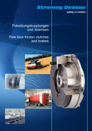
the effective transmission<br />
TECHNICAL<br />
MANUAL<br />
integrated<br />
continuously<br />
variable<br />
drive
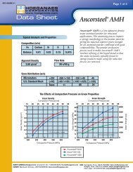
the effective transmission<br />
CLEAR DEMANDS!<br />
For certain applications, self-propelled agricultural<br />
and construction machinery, such as wheeled and<br />
telescopic loaders, forestry machines, <strong>com</strong>bine harvesters<br />
and also choppers, not only need to generate<br />
high tractive forces, but also have to be capable<br />
of covering long distances at the highest possible<br />
speed.<br />
Up to now, both of these functions have been realised by hydrostatic<br />
drives with <strong>manual</strong> gearboxes. This concept has proven to be<br />
less than optimum in practice, since the machine usually has to be<br />
at a standstill to switch between gears, making the procedure both<br />
inconvenient and time-consuming.<br />
Continuous variability is what is called for here in practice - with a<br />
variable drive concept and substantially greater operating convenience<br />
for the driver.<br />
OUR SOLUTION!<br />
GKN Walterscheid cooperated with SAUER BIBUS on<br />
developing a continuously variable, hydrostatic travel<br />
drive for self-propelled agricultural and construction<br />
machinery. The ICVD ® (Integrated Continuously<br />
Variable Drive) makes it possible to drive through the<br />
entire speed range without interrupting the tractive<br />
force.<br />
The ICVD ® is thus a symbiosis of time-proven drive concepts,<br />
<strong>com</strong>bining their advantages, but without having to accept the<br />
drawbacks of the old solutions.<br />
The ICVD ® is the only continuously variable, hydrostatic travel<br />
drive to use 45° large-angle technology and <strong>com</strong>prises a gearbox,<br />
a hydraulic motor and a control unit.<br />
2
3<br />
CONTENTS<br />
Characteristics .............................................................................................4<br />
<strong>Technical</strong> Data ..........................................................................................5 - 6<br />
Hydraulic Control .........................................................................................7<br />
ICVD ® GT-S1 N 233V ...............................................................................8 - 9<br />
ICVD ® GT-S1 A 233V............................................................................10 - 11<br />
ICVD ® GT-S2 A 233V ...........................................................................12 - 13<br />
ICVD ® GT-T2 N 233V/233V ................................................................14 - 15<br />
ICVD ® GT-T3 N 233V/233V ................................................................16 - 17<br />
ICVD ® MO-S0 N 233V .........................................................................18 - 19<br />
Safety ............................................................................................................20<br />
Data Sheet ....................................................................................................21<br />
Notes.......................................................................................................22 - 23<br />
the effective transmission
the effective transmission<br />
Continuously Variable Hydrostatic Drive with 45° Large-Angle Technology<br />
Type: Variable-displacement axial piston motor<br />
of bent-axis design for hydrostatic drives with open<br />
or closed circuit.<br />
The IVCD ® is a continuously variable, hydrostatic<br />
travel drive, <strong>com</strong>prising mechanical gearbox,<br />
hydraulic motor and control unit.<br />
CHARACTERISTICS<br />
> The entire speed range can be driven through<br />
without interrupting the tractive force<br />
> Automatic adaptation of the power requirement<br />
> Optimised efficiency thanks to integrated motor<br />
using large-angle technology<br />
> High power density and small dimensions<br />
> 45° large-angle technology offers a large,<br />
continuously variable conversion range<br />
> Low noise level<br />
> Reduced fuel consumption<br />
4
Continuously Variable Hydrostatic Drive with 45° Large-Angle Technology<br />
TECHNICAL DATA<br />
HYDRAULIC FLUIDS<br />
The operating data and ratings are based on operation with hydraulic<br />
fluids containing oxidation, rust and foam inhibitors. These<br />
fluids must display good thermal and hydrolytic stability in order<br />
to prevent wear, erosion and corrosion of the internal <strong>com</strong>ponents.<br />
The ICVD ® can also be operated using fire-resistant hydraulic<br />
fluids, but under modified conditions. Hydraulic fluids may not<br />
be mixed. Contact GKN Walterscheid or SAUER BIBUS service for<br />
further information.<br />
Suitable hydraulic fluids<br />
> Hydraulic fluids to DIN 51 524, Part 2 (HM)<br />
> Hydraulic fluids to DIN 51 524, Part 3 (HV)<br />
> API CD, CE and CF engine oils to SAE J183<br />
> M2C33F or G automatic transmission fluids (ATF)<br />
> Multi-purpose agricultural oils (STOU)<br />
Temperature<br />
The temperature and viscosity requirements must be met. The<br />
temperature should be within the limits indicated below. The<br />
minimum temperature does not affect the motor <strong>com</strong>ponents, but<br />
may have a negative impact on power transmission. The maximum<br />
temperature is dependent on the properties of the motor material.<br />
It must not be exceeded and is usually measured at the leakage-oil<br />
outlet.<br />
Temperature range 1)<br />
t min. = –20 °C Briefly, when starting cold<br />
t max. = 115 °C Briefly<br />
1) Measured at the hottest point, e.g. leakage-oil port<br />
Viscosity<br />
The viscosity should be within the re<strong>com</strong>mended range (see<br />
below) to achieve high efficiency and a long bearing service life.<br />
The minimum viscosity may only occur briefly at the maximum ambient<br />
temperature. The maximum viscosity may only occur under<br />
cold-starting conditions, i.e. at appropriately limited rpm speeds<br />
until the system has warmed up.<br />
Viscosity range<br />
Minimum = 7 mm 2 /s Briefly<br />
Re<strong>com</strong>mended = 12-80 mm 2 /s Re<strong>com</strong>mended operating<br />
viscosity<br />
Maximum = 1,600 mm 2 /s Briefly, when starting cold<br />
5<br />
FILTERING<br />
the effective transmission<br />
To prevent premature wear, it is essential that the hydrostatic drive<br />
system be charged and operated with clean hydraulic fluid only.<br />
The hydraulic fluid is considered to be a <strong>com</strong>ponent of the overall<br />
machine. The filter system to be used must guarantee cleanliness<br />
class 20/17/12 or better to ISO 4406 under normal operating<br />
conditions. The choice of filter is dependent on various factors, including<br />
the amount of dirt penetrating the system, the formation of<br />
dirt particles in the system, the necessary cleanliness of the fluid<br />
and the desired maintenance interval. The filters must be selected<br />
in such a way that the above-mentioned requirements are met,<br />
efficiency and performance being the underlying criteria.<br />
The respective demands on filtering in different systems must be<br />
determined by means of trials. The prerequisites for a definitive<br />
decision on the filter system are monitoring of the prototypes, and<br />
assessment of the <strong>com</strong>ponents and performance, throughout the<br />
entire test period.<br />
CAUTION!<br />
INDEPENDENT BRAKE SYSTEM<br />
Loss of the power connection in the driveline of a hydrostatic<br />
system during an acceleration or braking phase, or in the neutral<br />
position of the drive system, can lead to a loss of hydrostatic<br />
braking capacity. For this reason, a redundant brake system that<br />
is independent of the hydrostatic brake system must be installed.<br />
The redundant system must be in a position to brake the moving<br />
vehicle and/or to serve as a holding brake.
the effective transmission<br />
TECHNICAL DATA<br />
HYDRAULIC FLUID RESERVOIR<br />
Continuously Variable Hydrostatic Drive with 45° Large-Angle Technology<br />
The air contained in the hydraulic fluid is eliminated in the hydraulic<br />
fluid reservoir during the dwell time. Fluctuations in volume are<br />
also equalised. These can be caused by heating of the hydraulic<br />
fluid (expansion), cooling of the hydraulic fluid (contraction),<br />
actuation of differential cylinders. The hydraulic fluid reservoir<br />
must be capable of equalising the volumetric flow fluctuations<br />
under all operating conditions. The minimum reservoir capacity in<br />
litres should be 5/8 of the maximum charging-pump volumetric<br />
flow in l/min. The minimum fluid content to be provided is 1/2 of<br />
the charging-pump volumetric flow in l/min.<br />
This results in a dwell time of the fluid in the reservoir of 30<br />
seconds, allowing the air contained in the hydraulic fluid to rise<br />
to the surface of the fluid. If a reservoir is designed according to<br />
these guide values, a sufficient equalising volume is available<br />
for most systems/applications with closed reservoir (e.g. without<br />
breather). The suction port leading to the charging pump must be<br />
located above the reservoir bottom in order to prevent the aspiration<br />
of sediment. The return line port on the reservoir must be located<br />
below the fluid surface and as far as possible away from the<br />
suction port. Air elimination is improved by inclined, perforated<br />
interceptor plates, installed between the return and suction ports.<br />
POWER UNIT<br />
Type<br />
> Variable-displacement axial piston motor of bent-axis<br />
design for a closed or open circuit<br />
> Without control pressure (initial position), the power unit<br />
is at the maximum pivoting angle (closed circuit)<br />
Sense of rotation<br />
> Clockwise and counterclockwise<br />
Geometric displacement volume<br />
> Max. 233 cm 3 /rev.<br />
> Min. 40 cm 3 /rev.<br />
> Optionally 0 cm 3 /rev.<br />
Continuous speed<br />
> At max. pivoting angle: 1,500 rpm<br />
> At min. pivoting angle: 4,000 rpm<br />
Maximum speed (briefly):<br />
> At max. pivoting angle: 1,800 rpm<br />
> At min. pivoting angle: 4,200 rpm<br />
Pivoting angle<br />
> Max. 45°, min. 7°, optionally 0°<br />
> Theoretical specific torque: 3.7 Nm/bar<br />
HYDRAULIC PARAMETERS<br />
Operating pressure<br />
> Working pressure: max. Δp 480 bar<br />
> Max. pressure, briefly: Δp 510 bar<br />
Housing pressure<br />
> Max. continuous pressure: 2 bar; briefly 5 bar<br />
Filtering<br />
> Required cleanliness class to ISO 4406: 20/17/12 or better<br />
6
Continuously Variable Hydrostatic Drive with 45° Large-Angle Technology<br />
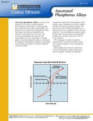
HYDRAULIC CONTROL<br />
1. CONTROL PRESSURE-DEPENDENT<br />
CONTROL<br />
Closed circuit<br />
7<br />
3<br />
3<br />
5<br />
4<br />
4<br />
3<br />
5<br />
4<br />
5<br />
1<br />
6<br />
2<br />
2<br />
8<br />
7<br />
5<br />
1<br />
6<br />
2<br />
7<br />
Motor 1<br />
Master motor<br />
Motor 2<br />
Slave motor<br />
1. Proportional control valve<br />
2. Stroke adjustment of the swivel yoke<br />
3. Pressure limiting valve, flushing (optional)<br />
4. Directional valve, flushing (optional)<br />
5. Pilot valve for control pressure reversal (optional)<br />
6. PCOR (optional)<br />
7. Control pressure shut-off (optional)<br />
8. Hydromechanical speed limitation (optional)<br />
2. ELECTRIC CONTROL<br />
Closed circuit<br />
3<br />
3<br />
3<br />
4<br />
4 5<br />
4<br />
1<br />
1<br />
2<br />
6<br />
the effective transmission<br />
2<br />
2
the effective transmission<br />
ICVD ® GT-S1 N 233V<br />
Kinematic diagram<br />
Continuously Variable Hydrostatic Drive with 45° Large-Angle Technology<br />
A<br />
B<br />
Transmission ratio i 0.94 - 1.6<br />
Torque at the output shaft Md 1,280 - 2,560 Nm<br />
Max. drive shaft operating angle 1) < 3° and Z-bend<br />
Drive shaft flange<br />
DIN ISO 7646<br />
120 x 8 x 10<br />
Operating pressure – max. (Δp) 480 bar<br />
Installation position Vertical 1)<br />
Mass (without fluids) m Approx. 140 kg<br />
Transmission oil quantity Approx. 4 l<br />
Transmission oil grade SAE 90 API-GL-5<br />
Hydraulic fluid quantity Approx. 15 l<br />
1) Other versions on request<br />
DIRECTION OF FLOW<br />
Sense of rotation Port A Port B<br />
Clockwise (CW) Outlet Inlet<br />
Counterclockwise (CCW) Inlet Outlet<br />
Definition of the sense of rotation: looking at the high-pressure ports on the control unit cover.<br />
MAINTENANCE AND OIL CHANGE<br />
Oil check after 100 hours of operation<br />
Oil change after 1,500 hours of operation or once per year<br />
8
Continuously Variable Hydrostatic Drive with 45° Large-Angle Technology<br />
DIMENSIONS - ICVD ® GT-S1 N 233V<br />
9<br />
~534<br />
~332<br />
<strong>MB</strong><br />
MA<br />
MV2<br />
PHD<br />
~543<br />
> High-pressure ports A + B: SAE 1" (6,000 psi),<br />
useable depth of thread 18 mm<br />
> Leakage-oil port T: M 26x1.5<br />
> Supply pressure ports PHD + Ps: M 14x1.5<br />
> Measuring ports MA, <strong>MB</strong>, M3: M 14x1.5<br />
> Measuring port M4: M 10x1<br />
Kindly request a binding installation drawing before finalising<br />
the design.<br />
T7<br />
M4<br />
T3<br />
T1<br />
PV1<br />
M3<br />
PS<br />
CCW<br />
B<br />
~165<br />
Optional:<br />
> Proportional control valve PV1: AMP-Junior<br />
> Travelling direction valve MV2: AMP-Junior<br />
A<br />
CW<br />
the effective transmission<br />
~120
the effective transmission<br />
ICVD ® GT-S1 A 233V<br />
Kinematic diagram<br />
A<br />
B<br />
Continuously Variable Hydrostatic Drive with 45° Large-Angle Technology<br />
A<br />
B<br />
Transmission ratio i 0.94 - 1.6<br />
Torque at the output shaft Md 1,600 - 3,200 Nm<br />
Max. drive shaft operating angle 1) < 3° and Z-bend<br />
Drive shaft flange<br />
Front<br />
Rear 1)<br />
DIN ISO 7646<br />
120 x 8 x 10<br />
120 x 8 x 10<br />
Operating pressure – max. (Δp) 480 bar<br />
Installation position Vertical 1)<br />
Mass (without fluids) m Approx. 150 kg<br />
Transmission oil quantity Approx. 3.7 l<br />
Transmission oil grade SAE 90 API-GL-5<br />
Hydraulic fluid quantity Approx. 15 l<br />
1) other versions on request<br />
CONNECTION FOR SUPPLEMENTARY MOTOR<br />
Connection to ISO 1<br />
Displacement volume 23-60 cm 3<br />
Flange ISO 3019-2<br />
Inside profile, max. DIN 5480-N30x2x30x14x9H<br />
DIRECTION OF FLOW<br />
Sense of rotation Port A Port B<br />
Clockwise (CW) Outlet Inlet<br />
Counterclockwise (CCW) Inlet Outlet<br />
Definition of the sense of rotation: looking at the high-pressure ports on the control unit cover.<br />
MAINTENANCE AND OIL CHANGE<br />
Oil check after 100 hours of operation<br />
Oil change after 1,500 hours of operation or once per year<br />
10
Continuously Variable Hydrostatic Drive with 45° Large-Angle Technology<br />
DIMENSIONS - ICVD ® GT-S1 A 233V<br />
11<br />
~534<br />
~332<br />
<strong>MB</strong><br />
MV2<br />
MA T7<br />
~543<br />
> High-pressure ports A + B: SAE 1" (6,000 psi),<br />
useable depth of thread 18 mm<br />
> Leakage-oil port T: M 26x1.5<br />
> Supply pressure ports PHD + Ps: M 14x1.5<br />
> Measuring ports MA, <strong>MB</strong>, M3: M 14x1.5<br />
> Measuring port M4: M 10x1<br />
Kindly request a binding installation drawing before finalising<br />
the design.<br />
M4<br />
T3<br />
PHD<br />
PV1<br />
T1<br />
M3<br />
PS<br />
CCW<br />
B A<br />
Optional:<br />
> Proportional control valve PV1: AMP-Junior<br />
> Travelling direction valve MV2: AMP-Junior<br />
CW<br />
~165<br />
the effective transmission<br />
~120
the effective transmission<br />
ICVD ® GT-S2 A 233V<br />
A<br />
B<br />
Kinematic diagram<br />
Continuously Variable Hydrostatic Drive with 45° Large-Angle Technology<br />
A<br />
B<br />
Transmission ratio i 1.7 - 2.2<br />
Torque at the output shaft Md 4,080 - 5,280 Nm<br />
Max. drive shaft operating angle 1) < 3° and Z-bend<br />
Drive shaft flange<br />
both sides 1)<br />
DIN ISO 7646<br />
120 x 8 x 10<br />
Operating pressure – max. (Δp) 480 bar<br />
Installation position Vertical 1)<br />
Mass (without fluids) m Approx. 185 kg<br />
Transmission oil quantity Approx. 6.5 l<br />
Transmission oil grade SAE 90 API-GL-5<br />
Hydraulic fluid quantity Approx. 1.5 l<br />
1) Other versions on request<br />
CONNECTION FOR SUPPLEMENTARY MOTOR<br />
Connection diagram to ISO 1<br />
Displacement volume 80-140 cm 3<br />
Flange ISO 3019-2<br />
Inside profile, max. DIN 5480-N30x2x30x14x9H<br />
DIRECTION OF FLOW<br />
Sense of rotation Port A Port B<br />
Clockwise (CW) Outlet Inlet<br />
Counterclockwise (CCW) Inlet Outlet<br />
Definition of the sense of rotation: looking at the high-pressure ports on the control unit cover.<br />
MAINTENANCE AND OIL CHANGE<br />
Oil check after 100 hours of operation<br />
Oil change after 1,500 hours of operation or once per year<br />
12
Continuously Variable Hydrostatic Drive with 45° Large-Angle Technology<br />
DIMENSIONS - ICVD ® GT-S2 A 233V<br />
13<br />
~671<br />
~423<br />
<strong>MB</strong><br />
~622<br />
MV2<br />
> High-pressure ports A + B: SAE 1" (6,000 psi),<br />
useable depth of thread 18 mm<br />
> Leakage-oil port T: M 26x1.5<br />
> Supply pressure ports PHD + Ps: M 14x1.5<br />
> Measuring ports MA, <strong>MB</strong>, M3: M 14x1.5<br />
> Measuring port M4: M 10x1<br />
Kindly request a binding installation drawing before finalising<br />
the design.<br />
MA<br />
PHD<br />
T7<br />
M4<br />
T3<br />
T1<br />
PV1<br />
M3<br />
PS<br />
CCW<br />
B<br />
A<br />
CW<br />
~212<br />
Optional:<br />
> Proportional control valve PV1: AMP-Junior<br />
> Travelling direction valve MV2: AMP-Junior<br />
the effective transmission<br />
~188<br />
~388
the effective transmission<br />
Continuously Variable Hydrostatic Drive with 45° Large-Angle Technology<br />
ICVD ® GT-T2 N 233V/233V<br />
A2<br />
B2<br />
Kinematic diagram<br />
A1<br />
B1<br />
Transmission ratio i 1.7 - 2.2<br />
Torque at the output shaft Md 5,440 - 7,040 Nm<br />
Max. drive shaft operating angle 1) < 3° and Z-bend<br />
Drive shaft flange<br />
both sides 1)<br />
DIN ISO 7646<br />
120 x 8 x 10<br />
Operating pressure – max. (Δp) 480 bar<br />
Installation position Vertical 1)<br />
Mass (without fluids) m Approx. 270 kg<br />
Transmission oil quantity Approx. 6.5 l<br />
Transmission oil grade SAE 90 API-GL-5<br />
Hydraulic fluid quantity<br />
1) Other versions on request<br />
DIRECTION OF FLOW<br />
Approx. 1.5 l<br />
per motor<br />
Sense of rotation Port A (A1 + B2) Port B (A2 + B1)<br />
Clockwise (CW) Outlet Inlet<br />
Counterclockwise (CCW) Inlet Outlet<br />
Definition of the sense of rotation: looking at the output flange on Motor 1 (see drawing on p. 15)<br />
MAINTENANCE AND OIL CHANGE<br />
Oil check after 100 hours of operation<br />
Oil change after 1,500 hours of operation or once per year<br />
14
Continuously Variable Hydrostatic Drive with 45° Large-Angle Technology<br />
DIMENSIONS - ICVD ® GT-T2 N 233V/ 233V<br />
15<br />
~675<br />
PV1.1<br />
T1.1<br />
T3.1<br />
M4.1<br />
T7.1 MA1<br />
MV2.1<br />
PHD1<br />
<strong>MB</strong>1<br />
A1<br />
M3.1<br />
PS1<br />
B2<br />
B1 A2<br />
<strong>MB</strong>2<br />
MA2<br />
M4.2<br />
PHD2 T1.2<br />
T7.1<br />
T3.2<br />
Motor 1 Motor 2<br />
Motor 1 Motor 2<br />
> High-pressure ports A + B: SAE 1" (6,000 psi),<br />
useable depth of thread 18 mm<br />
> Leakage-oil port T: M 26x1.5<br />
> Supply pressure ports PHD + Ps: M 14x1.5<br />
> Measuring ports MA, <strong>MB</strong>, M3: M 14x1.5<br />
> Measuring port M4: M 10x1<br />
Kindly request a binding installation drawing before finalising<br />
the design.<br />
M3.2<br />
CCW<br />
Optional:<br />
> Proportional control valve PV1.1: AMP-Junior<br />
> Travelling direction valve MV2.1: AMP-Junior<br />
the effective transmission<br />
CW
the effective transmission<br />
Continuously Variable Hydrostatic Drive with 45° Large-Angle Technology<br />
ICVD ® GT-T3 N 233V/233V<br />
A2<br />
B2<br />
Kinematic diagram<br />
A1<br />
B1<br />
Transmission ratio i 0.8 - 1.6<br />
Torque at the output shaft Md 2,560 - 5,120 Nm<br />
Max. drive shaft operating angle 1) < 3° and Z-bend<br />
Drive shaft flange<br />
both sides 1)<br />
DIN ISO 7646<br />
120 x 8 x 10<br />
Operating pressure – max. (Δp) 480 bar<br />
Installation position Vertical 1)<br />
Mass (without fluids) m Approx. 290 kg<br />
Transmission oil quantity Approx. 6.5 l<br />
Transmission oil grade SAE 90 API-GL-5<br />
Hydraulic fluid quantity<br />
1) Other versions on request<br />
DIRECTION OF FLOW<br />
Approx. 1.5 l<br />
per motor<br />
Sense of rotation Port A (A1 + B2) Port B (A2 + B1)<br />
Clockwise (CW) Outlet Inlet<br />
Counterclockwise (CCW) Inlet Outlet<br />
Definition of the sense of rotation: looking at the output flange on Motor 1 (see drawing on p. 17)<br />
MAINTENANCE AND OIL CHANGE<br />
Oil check after 100 hours of operation<br />
Oil change after 1,500 hours of operation or once per year<br />
16
Continuously Variable Hydrostatic Drive with 45° Large-Angle Technology<br />
DIMENSIONS - ICVD ® GT-T3 N 233V/ 233V<br />
17<br />
~675<br />
PV1.1<br />
T1.1<br />
T3.1<br />
Motor 1<br />
M4.1<br />
T7.1 MA1<br />
MV2.1<br />
PHD1<br />
<strong>MB</strong>1<br />
A1<br />
M3.1<br />
PS1<br />
B2<br />
B1 A2<br />
<strong>MB</strong>2<br />
MA2<br />
M4.2<br />
PHD2 T1.2<br />
T7.1<br />
T3.2<br />
Motor 2<br />
Motor 1 Motor 2<br />
> High-pressure ports A + B: SAE 1" (6,000 psi),<br />
useable depth of thread 18 mm<br />
> Leakage-oil port T: M 26x1.5<br />
> Supply pressure ports PHD + Ps: M 14x1.5<br />
> Measuring ports MA, <strong>MB</strong>, M3: M 14x1.5<br />
> Measuring port M4: M 10x1<br />
Kindly request a binding installation drawing before finalising<br />
the design.<br />
M3.2<br />
CCW<br />
Optional:<br />
> Proportional control valve PV1.1: AMP-Junior<br />
> Travelling direction valve MV2.1: AMP-Junior<br />
the effective transmission<br />
CW
the effective transmission<br />
ICVD ® MO-S0 N 233V<br />
Kinematic diagram<br />
Continuously Variable Hydrostatic Drive with 45° Large-Angle Technology<br />
A<br />
B<br />
Max. torque at power unit shaft Md 1,600 Nm<br />
Flange connection, ISO 3019+2 160B4HW<br />
Shaft profile, DIN 5480 W50x2x30x24x8f<br />
Operating pressure – max. (Δp) 480 bar<br />
Installation position Any<br />
Mass (without fluids) m Approx. 95 kg<br />
Hydraulic fluid quantity Approx. 1.5 l<br />
DIRECTION OF FLOW<br />
Sense of rotation Port A Port B<br />
Clockwise (CW) Outlet Inlet<br />
Counterclockwise (CCW) Inlet Outlet<br />
Definition of the sense of rotation: looking at the flange.<br />
MAINTENANCE AND OIL CHANGE<br />
Oil check after 100 hours of operation<br />
Oil change after 1,500 hours of operation or once per year<br />
18
Continuously Variable Hydrostatic Drive with 45° Large-Angle Technology<br />
DIMENSIONS - ICVD ® MO-S0 N 233V<br />
19<br />
~418<br />
~388<br />
T1<br />
~481<br />
> High-pressure ports A + B: SAE 1" (6,000 psi),<br />
useable depth of thread 18 mm<br />
> Leakage-oil port T: M 26x1.5<br />
> Supply pressure port Ps: M 14x1.5<br />
> Measuring ports MA, <strong>MB</strong>, M3: M 14x1.5<br />
> Measuring port M4: M 10x1<br />
M4<br />
<strong>MB</strong> MA<br />
Kindly request a binding installation drawing before finalising<br />
the design.<br />
P<br />
M3<br />
A<br />
B<br />
PV1<br />
CCW CW<br />
T3<br />
~205<br />
Optional:<br />
> Proportional control valve PV1: AMP-Junior<br />
> Travelling direction valve MV2: AMP-Junior<br />
the effective transmission<br />
~209
the effective transmission<br />
SAFETY<br />
Continuously Variable Hydrostatic Drive with 45° Large-Angle Technology<br />
The ICVD ® is designed and built according to the state of the art to<br />
be safe in operation. However, the ICVD ® can be a potential source<br />
of danger if used incorrectly, e.g. by untrained personnel, or for<br />
purposes for which it is not intended.<br />
This can result in<br />
> Threats to life and limb,<br />
> Threats to machines and other property of the user,<br />
> Threats to efficient working of the applications.<br />
Anyone involved in the installation, <strong>com</strong>missioning, operation and<br />
maintenance of the ICVD ® must have read and understood the<br />
<strong>manual</strong>. Appropriate training is offered by GKN Walterscheid and<br />
SAUER BIBUS.<br />
The ICVD ® is intended for use in open or closed circuits. The persons<br />
responsible for the safety of the installation must ensure that<br />
> Only qualified persons are <strong>com</strong>missioned with work on the ICVD ® ,<br />
> These persons always have the operating instructions and<br />
other product documentation at their disposal whenever they<br />
are working on or with the ICVD ® and are <strong>com</strong>mitted to consist -<br />
ently <strong>com</strong>ply with all these documents,<br />
> Non-qualified persons are banned from working on the ICVD ®<br />
or in its vicinity.<br />
Qualified personnel means persons who - based on their training,<br />
experience and instruction, as well as their knowledge of pertinent<br />
standards, rules, accident prevention regulations and operating<br />
conditions - have been authorised, by the person responsible for<br />
the safety of the installation, to perform the activities necessary<br />
from time to time and are in a position to recognise and avoid<br />
possible hazards in this context. Among other things, a knowledge<br />
of First Aid measures and the local emergency facilities is also<br />
necessary.<br />
It is presupposed that the fundamental planning work for the<br />
entire installation, and all work relating to transport, assembly,<br />
installation, <strong>com</strong>missioning, maintenance and repair, are perf<br />
ormed by personnel qualified in the respective field and/or<br />
checked by responsible specialists.<br />
Particular attention must be paid to the following:<br />
> The technical data and other information regarding permissible<br />
use (installation, connection, ambient and operating conditions),<br />
which are to be found in, for example, the catalogue, the con-<br />
tract documents, the operating <strong>manual</strong>, the rating plate data<br />
and other product documentation,<br />
> The general construction and safety regulations,<br />
> The local, installation-specific provisions and requirements,<br />
> The correct use of tools, hoisting gear and transport facilities,<br />
> The use of personal protective equipment.<br />
If anything is unclear in this respect, particularly if detailed, product-specific<br />
information is not available, GKN Walterscheid and<br />
SAUER BIBUS must be contacted to clarify the situation. When<br />
doing so, kindly always quote the Type Designation and Identification<br />
Number.<br />
The prescribed maintenance, inspection and overhauling measures<br />
must be performed regularly in order to prevent malfunctions.<br />
Changes <strong>com</strong>pared to normal operation (greater power consumption,<br />
higher temperatures or vibrations, unusual noises or smells,<br />
tripping of monitoring devices, etc.) indicate that the system is<br />
not functioning correctly. In such cases, the responsible maintenance<br />
personnel must be informed without delay in order to avoid<br />
malfunctions, which could in turn indirectly or directly bring about<br />
serious personal injury or property damage.<br />
IN CASE OF DOUBT, SWITCH OFF THE ICVD ® IMMEDIATELY!<br />
20
Continuously Variable Hydrostatic Drive with 45° Large-Angle Technology<br />
APPLICATION DATA<br />
21<br />
Company * Contact *<br />
Address * Phone *<br />
Date * E-Mail *<br />
1. Application / Model *<br />
2. Prime Mover 3. Vehicle Max. Min.<br />
the effective transmission<br />
a) Type / Model a) Weight * [kg ]<br />
b) Nominal Power / Speed * [kW] b) Front Axle Load * [kg ]<br />
c) Engine Speed for Calculation * [rpm] c) Tyre – Type<br />
d) Max. Engine Speed [rpm] d) Tyre – Static Radius * [mm]<br />
4. Max. Power for Hydrostatic Drive [kW]<br />
5. <strong>Technical</strong> Data – Hydrostatic Drive<br />
A. Pump B. Hydraulic Motor<br />
a) Type / Model * a) Type / Model<br />
b) Max. Displacement * [cc/rev] b) Max. Displacement * [cc/rev]<br />
c) Max. Pressure * [bar] c) Max. Pressure * [bar]<br />
d) Max. Speed [rpm] d) Max. Speed * [rpm]<br />
e) Charge Pressure * [bar]<br />
f ) Position > on Prime Mover yes no [ ]<br />
> with Intermediate Gearbox (Ratio) [1]<br />
6. <strong>Technical</strong> Data – Mechanical Drive 7. System Parameters<br />
A. Transmission Ratio a) Max. Speed * [kph]<br />
a) Axle Ratio [1] b) Min. Operating Speed [kph]<br />
b) Gearbox Ratios 1st Gear [1] c) Max. Tractive Force * [kN]<br />
8. Comments (please attach additional Drafts / Diagrams)<br />
* These fields must be <strong>com</strong>pleted<br />
2nd Gear [1] d) Rolling Resistance * f [1]<br />
3rd Gear [1] e) Max. Gradeability > unloaded [%]<br />
4th Gear [1] > loaded [%]<br />
f) Trailer Weight [kg]<br />
See also www.icvd.info/Downloads
NOTES<br />
the effective transmission<br />
Continuously Variable Hydrostatic Drive with 45° Large-Angle Technology<br />
22
Continuously Variable Hydrostatic Drive with 45° Large-Angle Technology<br />
23<br />
the effective transmission<br />
NOTES
the effective transmission<br />
CONTACT<br />
GKN WALTERSCHEID G<strong>MB</strong>H<br />
Wolfgang Adamek<br />
Hauptstrasse 150<br />
D-53797 Lohmar, Germany<br />
Tel.: +49 2246 12-35 62<br />
Fax: +49 2246 12-74 562<br />
service@icvd.info<br />
www.icvd.info<br />
SAUER BIBUS G<strong>MB</strong>H<br />
Ralf Schrempp<br />
Lise-Meitner-Ring 13<br />
D-89231 Neu-Ulm, Germany<br />
AK0,4-1<br />
Tel.: +49 731 1896-0<br />
0409<br />
Fax: +49 731 1896-119<br />
GB<br />
info@sauerbibus.de<br />
www.icvd.info ICVD2