The Surface Finish Effect on the Creep Corrosion in PCB - IPC Outlook
The Surface Finish Effect on the Creep Corrosion in PCB - IPC Outlook
The Surface Finish Effect on the Creep Corrosion in PCB - IPC Outlook

Create successful ePaper yourself
Turn your PDF publications into a flip-book with our unique Google optimized e-Paper software.
Abstract<br />
<str<strong>on</strong>g>The</str<strong>on</strong>g> <str<strong>on</strong>g>Surface</str<strong>on</strong>g> <str<strong>on</strong>g>F<strong>in</strong>ish</str<strong>on</strong>g> <str<strong>on</strong>g>Effect</str<strong>on</strong>g> <strong>on</strong> <strong>the</strong> <strong>Creep</strong> Corrosi<strong>on</strong> <strong>in</strong> <strong>PCB</strong><br />
1 Cherie Chen*, 1 Jeffrey ChangB<strong>in</strong>g Lee, 1 Graver Chang, 1 Jandel L<strong>in</strong><br />
2 Casa Hsieh, 2 Jesse Liao, 2 Jerry Huang<br />
1 IST-Integrated Service Technology, Inc.<br />
2 Tripod Technology Corporati<strong>on</strong><br />
1 Hs<strong>in</strong>chu City, Taiwan<br />
<strong>Creep</strong> corrosi<strong>on</strong> normally happens <strong>in</strong> <strong>the</strong> end system, <strong>PCB</strong>, c<strong>on</strong>nectors and comp<strong>on</strong>ents are widely noted due to <strong>the</strong> exposure of<br />
high sulfur envir<strong>on</strong>ments under elevated humidity. In this study, <strong>the</strong> major focus is <strong>the</strong> <strong>in</strong>vestigati<strong>on</strong> of <strong>PCB</strong>s with 3 different<br />
types of surface f<strong>in</strong>ish (ImAg, Post-Treatment ImAg, HT-OSP), SMD vs NSMD and n<strong>on</strong> clean organic acid flux residue from<br />
simulat<strong>in</strong>g wave solder<strong>in</strong>g process under MFG Test (Mixed Flow<strong>in</strong>g Gas Test). <str<strong>on</strong>g>The</str<strong>on</strong>g> realistic mixed flow<strong>in</strong>g gas (H2S, SO2, NO2,<br />
Cl2) at certa<strong>in</strong> c<strong>on</strong>centrati<strong>on</strong> of each and relative humidity are designed to accelerate creep corrosi<strong>on</strong> happen<strong>in</strong>g.<br />
One of <strong>the</strong> purposes <strong>in</strong> this study is to <strong>in</strong>vestigate <strong>the</strong> effect of <strong>the</strong> mixed flow<strong>in</strong>g gas with various H2S c<strong>on</strong>centrati<strong>on</strong> (500 ppb,<br />
1000 ppb, 1700 ppb) at 5 days durati<strong>on</strong> <strong>on</strong> <strong>the</strong> corrosi<strong>on</strong> rate (nm/day) <strong>in</strong> <strong>the</strong> Cu coup<strong>on</strong> and Ag coup<strong>on</strong> <strong>in</strong> order to understand<br />
how H2S drives <strong>the</strong> corrosi<strong>on</strong> accelerati<strong>on</strong>. <str<strong>on</strong>g>The</str<strong>on</strong>g> data are also verified by <strong>the</strong> methods of Weight Ga<strong>in</strong> Analysis and X-Secti<strong>on</strong><br />
with SEM/EDX.<br />
<str<strong>on</strong>g>The</str<strong>on</strong>g> result shows much higher corrosi<strong>on</strong> rates are observed <strong>on</strong> Cu coup<strong>on</strong> <strong>in</strong> both Individual and Mixed Flow<strong>in</strong>g Gas Tests. <str<strong>on</strong>g>The</str<strong>on</strong>g><br />
corrosi<strong>on</strong> rate of Cu coup<strong>on</strong> rapidly <strong>in</strong>creases with H2S c<strong>on</strong>centrati<strong>on</strong> above 1000 ppb. Ag coup<strong>on</strong> have more active corrosi<strong>on</strong> <strong>in</strong><br />
low H2S c<strong>on</strong>centrati<strong>on</strong> than high H2S c<strong>on</strong>centrati<strong>on</strong>. Flak<strong>in</strong>g corrosi<strong>on</strong> also happens <strong>on</strong> <strong>the</strong> Cu coup<strong>on</strong> with heavy corrosi<strong>on</strong><br />
product <strong>in</strong> <strong>the</strong> high H2S c<strong>on</strong>centrati<strong>on</strong> test c<strong>on</strong>diti<strong>on</strong>. And more visible creep corrosi<strong>on</strong> is observed <strong>on</strong> HT-OSP f<strong>in</strong>ished circuit<br />
boards and SMD, as <strong>the</strong> residue of organic acid flux residue is not able to prevent corrosi<strong>on</strong> occurrence.<br />
Key Words: <strong>Creep</strong> Corrosi<strong>on</strong>, <str<strong>on</strong>g>Surface</str<strong>on</strong>g> <str<strong>on</strong>g>F<strong>in</strong>ish</str<strong>on</strong>g>, Organic Acid Flux, Mixed Flow<strong>in</strong>g Gas Test (MFG), SMD, NSMD<br />
Introducti<strong>on</strong><br />
As orig<strong>in</strong>ally published <strong>in</strong> <strong>the</strong> <strong>IPC</strong> APEX EXPO Proceed<strong>in</strong>gs.<br />
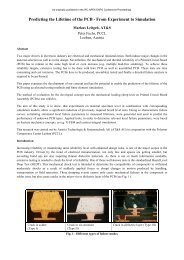
Many volcanoes erupted <strong>in</strong> Iceland, Japan, Ind<strong>on</strong>esia and <strong>the</strong> Philipp<strong>in</strong>es <strong>in</strong> <strong>the</strong> recent two years. <str<strong>on</strong>g>The</str<strong>on</strong>g>re are 2,000 ext<strong>in</strong>ct<br />
volcanoes and 523 active volcanoes distributed <strong>in</strong> four major volcanic belts <strong>in</strong> <strong>the</strong> world. <str<strong>on</strong>g>The</str<strong>on</strong>g>re are twenty volcanic erupti<strong>on</strong>s at<br />
any time and volcanic activity <strong>in</strong>creased significantly s<strong>in</strong>ce year 2000. This released more sulfides pos<strong>in</strong>g a threat to <strong>the</strong><br />
envir<strong>on</strong>ment. <str<strong>on</strong>g>The</str<strong>on</strong>g> general and volcanic gas compositi<strong>on</strong>s are shown <strong>in</strong> Figure 2. H2O and SO2 released <strong>in</strong>to <strong>the</strong> air may cause<br />
corrosi<strong>on</strong> after a volcanic erupti<strong>on</strong>.<br />
Figure 1. <str<strong>on</strong>g>The</str<strong>on</strong>g> major volcanic belts <strong>in</strong> <strong>the</strong> world.
Figure 2. <str<strong>on</strong>g>The</str<strong>on</strong>g> comparis<strong>on</strong> of general and volcanic gas compositi<strong>on</strong>s.<br />
<str<strong>on</strong>g>The</str<strong>on</strong>g>re are many types of active sulfur compounds that are able to cause corrosi<strong>on</strong>. <str<strong>on</strong>g>The</str<strong>on</strong>g> creep corrosi<strong>on</strong> is <strong>the</strong> mass transport<br />
process where solid corrosi<strong>on</strong> products migrate over a surface without <strong>the</strong> <strong>in</strong>volvement of an electric field. [1] <str<strong>on</strong>g>The</str<strong>on</strong>g> comparis<strong>on</strong><br />
am<strong>on</strong>g <strong>Creep</strong> Corrosi<strong>on</strong>, Dendrite, and CAF is shown <strong>in</strong> Table 1, which illustrate different mechanism to electrical failure. [2]<br />
Table 1. <str<strong>on</strong>g>The</str<strong>on</strong>g> comparis<strong>on</strong> am<strong>on</strong>g <strong>Creep</strong> Corrosi<strong>on</strong>, Dendrite and CAF. [2]<br />
Comparis<strong>on</strong><br />
<strong>Creep</strong><br />
Corrosi<strong>on</strong><br />
Dendrite CAF<br />
Substrate Cu Cu/Ag/T<strong>in</strong>-<br />
Lead…<br />
Cu<br />
Corrosi<strong>on</strong><br />
Product<br />
Cu2S<br />
FO Cu Oxide/<br />
Hydroxide<br />
Electr<strong>on</strong> X Cathode to Anode to<br />
Migrati<strong>on</strong><br />
Anode Cathode<br />
Failure Mode Short /<br />
Open<br />
Short Short<br />
Humidity<br />
Requirement<br />
Yes Yes Yes<br />
Voltage<br />
Requirement<br />
No Yes Yes<br />
As orig<strong>in</strong>ally published <strong>in</strong> <strong>the</strong> <strong>IPC</strong> APEX EXPO Proceed<strong>in</strong>gs.<br />
<str<strong>on</strong>g>The</str<strong>on</strong>g> mechanism of creep corrosi<strong>on</strong> <strong>in</strong> Dr. P<strong>in</strong>g Zhao’s previous published paper described <strong>the</strong> process of Dissoluti<strong>on</strong> →<br />
Diffusi<strong>on</strong> → Re-depositi<strong>on</strong>. <str<strong>on</strong>g>The</str<strong>on</strong>g> multiple m<strong>on</strong>o-layers of water are adsorbed <strong>on</strong> <strong>the</strong> surface under high relative humidity and<br />
<strong>the</strong>n <strong>the</strong> corrosi<strong>on</strong> products dissolve <strong>in</strong>to <strong>the</strong>se water layers. <str<strong>on</strong>g>The</str<strong>on</strong>g>refore, <strong>the</strong>y diffuse over <strong>the</strong> surface <strong>in</strong> soluti<strong>on</strong> down <strong>the</strong><br />
c<strong>on</strong>centrati<strong>on</strong> gradient and re-deposit. <str<strong>on</strong>g>The</str<strong>on</strong>g> mechanism of creep corrosi<strong>on</strong> is shown <strong>in</strong> Figure 3. [3]<br />
Figure 3. <str<strong>on</strong>g>The</str<strong>on</strong>g> mechanism of creep corrosi<strong>on</strong> from Dr. P<strong>in</strong>g Zhao’s previous published paper[3]<br />
<str<strong>on</strong>g>The</str<strong>on</strong>g>re are a number of factors that lead to creep corrosi<strong>on</strong> <strong>in</strong> <strong>PCB</strong>s, as shown <strong>in</strong> Table 2. In this paper, <strong>the</strong> study is focused <strong>on</strong> <strong>the</strong><br />
factors of <strong>PCB</strong> board design (SMD vs NSMD), surface f<strong>in</strong>ish, flux residue <strong>in</strong> wave solder<strong>in</strong>g and MFG test c<strong>on</strong>diti<strong>on</strong>s. <str<strong>on</strong>g>The</str<strong>on</strong>g><br />
creep corrosi<strong>on</strong> <strong>on</strong> a <strong>PCB</strong> will <strong>in</strong>duce electrical failure <strong>in</strong> <strong>the</strong> electr<strong>on</strong>ic product. Obvious corroded <strong>PCB</strong>s are identified <strong>in</strong> some<br />
locati<strong>on</strong>s with elevated level of sulfur-based gases, <strong>in</strong>clud<strong>in</strong>g paper mills, waste-water treatment plants, landfills, swamps, and<br />
exit / entrance ramp, especially <strong>in</strong> <strong>the</strong> develop<strong>in</strong>g countries. [4]<br />
Table 2. <str<strong>on</strong>g>The</str<strong>on</strong>g> factors to creep corrosi<strong>on</strong><br />
Factors to <strong>Creep</strong> Corrosi<strong>on</strong> Studied <strong>in</strong> this paper<br />
1 <strong>PCB</strong> board design v<br />
2 <str<strong>on</strong>g>Surface</str<strong>on</strong>g> <str<strong>on</strong>g>F<strong>in</strong>ish</str<strong>on</strong>g><br />
v<br />
3 Flux residue<br />
v<br />
4 Solder Mask Geometry v<br />
5 Solder Paste Coverage
6 Reflow<br />
7 Wave Solder<strong>in</strong>g process<br />
8 MFG Test C<strong>on</strong>diti<strong>on</strong>s v<br />
In <strong>the</strong> electr<strong>on</strong>ic <strong>in</strong>dustry, <strong>the</strong>re have been a number of test methods developed to evaluate <strong>the</strong> corrosi<strong>on</strong> resistance from <strong>the</strong> view<br />
po<strong>in</strong>t of <strong>PCB</strong> materials, <strong>PCB</strong> assembly process and gas c<strong>on</strong>diti<strong>on</strong>. <str<strong>on</strong>g>The</str<strong>on</strong>g> MFG test method was carried out <strong>in</strong> 1980’s. It’s <strong>the</strong><br />
primary test method used currently <strong>in</strong> <strong>the</strong> electr<strong>on</strong>ic <strong>in</strong>dustry.<br />
<str<strong>on</strong>g>The</str<strong>on</strong>g> MFG test is a laboratory test where <strong>the</strong> temperature (℃), relative humidity (%RH), c<strong>on</strong>centrati<strong>on</strong> of gaseous pollutants (ppb<br />
level), and o<strong>the</strong>r critical variables (such as volume exchange rate and airflow rate) are carefully def<strong>in</strong>ed, m<strong>on</strong>itored and<br />
c<strong>on</strong>trolled. [5] <str<strong>on</strong>g>The</str<strong>on</strong>g> purpose of MFG test is to use <strong>the</strong> comb<strong>in</strong>ati<strong>on</strong> of four most comm<strong>on</strong> corrosive gases <strong>in</strong> <strong>the</strong> envir<strong>on</strong>ment, H2S,<br />
Cl2, NO2, SO2 to simulate and accelerate atmospheric corrosi<strong>on</strong> due to exposure. Many specific and applicati<strong>on</strong>-oriented MFG<br />
test methods created for <strong>in</strong>dustrial applicati<strong>on</strong>s are shown <strong>in</strong> Table 3. [6][7][8][9]<br />
But <strong>the</strong>re is still no accepted <strong>in</strong>dustry standard created for MFG test to correlate to real service life yet. From <strong>the</strong> literature<br />
published, <strong>the</strong> critical factor that causes creep corrosi<strong>on</strong> is <strong>the</strong> c<strong>on</strong>centrati<strong>on</strong> of H2S. <strong>IPC</strong> 3-11g Corrosi<strong>on</strong> of Metal <str<strong>on</strong>g>F<strong>in</strong>ish</str<strong>on</strong>g> Task<br />
Group also had a draft discussi<strong>on</strong> for sett<strong>in</strong>g 1500ppb possibility as <strong>the</strong> m<strong>in</strong>imum c<strong>on</strong>centrati<strong>on</strong> of H2S <strong>in</strong> <strong>IPC</strong>/APEX 2011.<br />
Fur<strong>the</strong>r progress will be updated <strong>in</strong> <strong>the</strong> next publicati<strong>on</strong>.<br />
Table3. MFG test methods for <strong>in</strong>dustrial applicati<strong>on</strong>s c<strong>on</strong>centrati<strong>on</strong>: (unit: ppb) [6][7][8][9]<br />
C<strong>on</strong>diti<strong>on</strong> Class H2S CL2 NO2 S02 Temp RH<br />
Telcordia<br />
Indoor 10 10 200 100 30℃ 70%<br />
Outdoor 100 20 200 200 30℃ 70%<br />
ALU Intl. 1500-2000 20 200 200 40℃ 70%<br />
Battelle<br />
EIA<br />
IEC<br />
Class 2 10 10 200 - 30℃ 70%<br />
Class 3 100 20 200 - 30℃ 75%<br />
Class 4 200 50 200 - 50℃ 75%<br />
II 10 10 200 - 30℃ 70%<br />
II A 10 10 200 100 30℃ 70%<br />
III 100 20 200 - 30℃ 75%<br />
IIIA 100 20 200 200 30℃ 70%<br />
IV 200 30 200 - 40℃ 75%<br />
1 100 - - 500 25℃ 75%<br />
2 10 10 200 - 30℃ 70%<br />
3 100 20 200 - 30℃ 75%<br />
4 10 10 200 200 25℃ 75%<br />
IBM 40 3 610 350 30℃ 70%<br />
Experiment<br />
1. MFG test set up<br />
a. Chamber feature is shown <strong>in</strong> figure 4<br />
b. MFG Test Flow<br />
As orig<strong>in</strong>ally published <strong>in</strong> <strong>the</strong> <strong>IPC</strong> APEX EXPO Proceed<strong>in</strong>gs.<br />
Figure 4. MFG test system <strong>in</strong> IST’s lab.<br />
Figure 5 shows <strong>the</strong> flow chart. 4 k<strong>in</strong>ds of <strong>in</strong>dividual gas com<strong>in</strong>g from <strong>the</strong> bottom side are mixed before gett<strong>in</strong>g <strong>in</strong>to <strong>the</strong><br />
chamber. <str<strong>on</strong>g>The</str<strong>on</strong>g> gas flow <strong>in</strong> <strong>the</strong> chamber is com<strong>in</strong>g from <strong>the</strong> bottom side. <str<strong>on</strong>g>The</str<strong>on</strong>g> gas emissi<strong>on</strong> com<strong>in</strong>g from <strong>the</strong> chamber first goes
<strong>in</strong>to Filter Tank for neutralizati<strong>on</strong> and <strong>the</strong>n goes to Active Carb<strong>on</strong> for deodorizati<strong>on</strong>. <str<strong>on</strong>g>The</str<strong>on</strong>g> f<strong>in</strong>al gas emissi<strong>on</strong> is n<strong>on</strong>-toxic and<br />
n<strong>on</strong>-pollut<strong>in</strong>g.<br />
c. Uniformity measurement <strong>in</strong> <strong>the</strong> MFG chamber<br />
Figure 5. IST MFG test flow chart<br />
In order to make sure that each board will experience <strong>the</strong> same test c<strong>on</strong>diti<strong>on</strong>s and <strong>the</strong> test boards <strong>in</strong>stalled <strong>in</strong> <strong>the</strong> chamber will<br />
not be <strong>in</strong>terfere with <strong>the</strong> gas flow it is necessary to verify <strong>the</strong> corrosi<strong>on</strong> level <strong>in</strong> different locati<strong>on</strong>s of <strong>the</strong> chamber. A total of<br />
12 Cu coup<strong>on</strong>s and 12 Ag coup<strong>on</strong>s with 99.99% purity (1 <strong>in</strong>ch x 1 <strong>in</strong>ch) are cleaned through proprietary chemical clean<strong>in</strong>g<br />
procedure and hung <strong>in</strong> different area of <strong>the</strong> chamber with some test boards for 5 days exposure with various H2S c<strong>on</strong>centrati<strong>on</strong><br />
(500 ppb, 1000 ppb, 1700 ppb) to understand how H2S drives <strong>the</strong> corrosi<strong>on</strong> accelerati<strong>on</strong>. <str<strong>on</strong>g>The</str<strong>on</strong>g> chamber set up is shown <strong>in</strong><br />
Figure 6. <str<strong>on</strong>g>The</str<strong>on</strong>g> weight ga<strong>in</strong> after <strong>the</strong> test c<strong>on</strong>firms whe<strong>the</strong>r <strong>the</strong> corrosi<strong>on</strong> degrees <strong>in</strong> different locati<strong>on</strong>s of <strong>the</strong> chamber are all <strong>in</strong><br />
<strong>the</strong> reas<strong>on</strong>able range and make sure <strong>the</strong> gas c<strong>on</strong>centrati<strong>on</strong> <strong>in</strong>side <strong>the</strong> chamber is stable and uniform. <str<strong>on</strong>g>The</str<strong>on</strong>g> weight ga<strong>in</strong> and<br />
corrosi<strong>on</strong> product of each coup<strong>on</strong> is verified by <strong>the</strong> methods of Weight Ga<strong>in</strong> Analysis, X-Secti<strong>on</strong> and u-XPS to def<strong>in</strong>e<br />
acceptable uniformity.<br />
d. Test c<strong>on</strong>diti<strong>on</strong><br />
Figure 6. Chamber set up of uniformity test<br />
<str<strong>on</strong>g>The</str<strong>on</strong>g> critical factor of creep corrosi<strong>on</strong> is <strong>the</strong> c<strong>on</strong>centrati<strong>on</strong> of H2S, which has been already been shown <strong>in</strong> previously published<br />
papers. In order to get more visible creep corrosi<strong>on</strong> phenomen<strong>on</strong>, 1700 ppb is chosen for <strong>the</strong> c<strong>on</strong>centrati<strong>on</strong> of H2S <strong>in</strong> this<br />
experiment based <strong>on</strong> <strong>the</strong> ALU’s study. [10] <str<strong>on</strong>g>The</str<strong>on</strong>g> MFG test c<strong>on</strong>diti<strong>on</strong> <strong>in</strong> this study is shown <strong>in</strong> Table 4.<br />
Table 4. MFG Test C<strong>on</strong>diti<strong>on</strong> <strong>in</strong> this experiment (ppb)<br />
H2S Cl2 NO2 SO2 Temp. RH Durati<strong>on</strong><br />
1700 20 200 200 40℃ 90% 21days<br />
Before MFG test, all of <strong>the</strong> test boards are reflowed <strong>on</strong>e time. <str<strong>on</strong>g>The</str<strong>on</strong>g> reflow profile is shown <strong>in</strong> Figure 7. After reflow, all <strong>PCB</strong>s are<br />
placed <strong>in</strong> <strong>the</strong> MFG chamber <strong>in</strong> figure 8.<br />
As orig<strong>in</strong>ally published <strong>in</strong> <strong>the</strong> <strong>IPC</strong> APEX EXPO Proceed<strong>in</strong>gs.
Figure 7.<str<strong>on</strong>g>The</str<strong>on</strong>g> reflow profile prior to MFG test<br />
Figure 8. <strong>PCB</strong> placement for MFG Test<br />
2. <strong>PCB</strong> design<br />
As orig<strong>in</strong>ally published <strong>in</strong> <strong>the</strong> <strong>IPC</strong> APEX EXPO Proceed<strong>in</strong>gs.<br />
Table 5 shows <strong>the</strong> DOE matrix to <strong>in</strong>vestigate material, process and design effect <strong>on</strong> <strong>the</strong> creep corrosi<strong>on</strong>. Two groups A and B of<br />
sample are <strong>in</strong>vestigated <strong>in</strong> this study. Group A is NSMD. (See Figure 9) Group B is Comb-Pattern design. (See Figure 10)<br />
Table 5. Test Vehicle of <strong>the</strong> DOE matrix<br />
Group Test Vehicle Feature Factors to study<br />
A HF <strong>PCB</strong> 80 x 80 mm NSMD <str<strong>on</strong>g>Surface</str<strong>on</strong>g> <str<strong>on</strong>g>F<strong>in</strong>ish</str<strong>on</strong>g>:<br />
B HF <strong>PCB</strong> 80 x 80 mm SMD<br />
Comb L<strong>in</strong>e<br />
1) ImAg<br />
2) Post-Treatment ImAg<br />
3) HT OSP 1 ; HTOSP 2<br />
Flux:<br />
Flux 1 ; Flux 2<br />
Figure 9: Test board design of Group A
a. SMD vs NSMD is shown <strong>in</strong> Figure 11<br />
b. <str<strong>on</strong>g>Surface</str<strong>on</strong>g> f<strong>in</strong>ish comparis<strong>on</strong> is shown <strong>in</strong> table 6<br />
c. Flux residue <strong>in</strong> wave solder<strong>in</strong>g<br />
Figure 10: Test board design of Group B<br />
Figure 11. SMD vs NSMD features<br />
Table 6: <str<strong>on</strong>g>The</str<strong>on</strong>g> descripti<strong>on</strong> of surface f<strong>in</strong>ishes vehicle<br />
In Group B, two types NC(No Clean) and OA(Organic Acid) Flux are sprayed <strong>on</strong> <strong>PCB</strong> with <strong>the</strong> simulati<strong>on</strong> of wave solder<strong>in</strong>g<br />
c<strong>on</strong>diti<strong>on</strong> by bak<strong>in</strong>g <strong>the</strong> flux residue <strong>on</strong> <strong>the</strong> <strong>PCB</strong>.<br />
<strong>PCB</strong>s of Group B are put <strong>in</strong> <strong>the</strong> oven at 125℃ for 5 m<strong>in</strong>utes and <strong>the</strong>n at 270℃ for 1 m<strong>in</strong>ute after <strong>the</strong> NC OA Flux are<br />
sprayed <strong>on</strong> it to simulate wave solder<strong>in</strong>g c<strong>on</strong>diti<strong>on</strong> and have flux residue rema<strong>in</strong><strong>in</strong>g <strong>on</strong> <strong>the</strong> <strong>PCB</strong>.<br />
Result and Discussi<strong>on</strong><br />
a. Uniformity Test<br />
As orig<strong>in</strong>ally published <strong>in</strong> <strong>the</strong> <strong>IPC</strong> APEX EXPO Proceed<strong>in</strong>gs.<br />
Experiment <str<strong>on</strong>g>Surface</str<strong>on</strong>g> <str<strong>on</strong>g>F<strong>in</strong>ish</str<strong>on</strong>g> Supplier<br />
Group A<br />
ImAg Vendor 1<br />
Post-Treatment ImAg Vendor 2<br />
HT OSP 1 Vendor 3<br />
HT OSP 2 Vendor 2<br />
Group B ImAg Vendor 1<br />
Before and after <strong>the</strong> uniformity test, 5 weight<strong>in</strong>gs are c<strong>on</strong>ducted by <strong>the</strong> microbalance and <strong>the</strong> average is calculated. After <strong>the</strong><br />
weight ga<strong>in</strong>, corrosi<strong>on</strong> product is verified by <strong>the</strong> methods of Weight Ga<strong>in</strong> Analysis, Coulometeric Reducti<strong>on</strong>(CR) and<br />
X-Secti<strong>on</strong> with SEM/EDS.(See Figure 12 and Figure 13.) <str<strong>on</strong>g>The</str<strong>on</strong>g> data from <strong>the</strong> three methods are c<strong>on</strong>sistent with each o<strong>the</strong>r. It<br />
can be def<strong>in</strong>ed that <strong>the</strong> gas <strong>in</strong>side of <strong>the</strong> chamber is uniform.<br />
<str<strong>on</strong>g>The</str<strong>on</strong>g> effect of <strong>the</strong> mixed flow<strong>in</strong>g gas with various H2S c<strong>on</strong>centrati<strong>on</strong> (500 ppb, 1000 ppb, 1700 ppb) at 5 days durati<strong>on</strong><br />
showed that a much higher corrosi<strong>on</strong> rate is observed <strong>on</strong> Cu coup<strong>on</strong>s <strong>in</strong> both <strong>the</strong> Individual and Mixed Flow<strong>in</strong>g Gas Test.
As orig<strong>in</strong>ally published <strong>in</strong> <strong>the</strong> <strong>IPC</strong> APEX EXPO Proceed<strong>in</strong>gs.<br />
<str<strong>on</strong>g>The</str<strong>on</strong>g> corrosi<strong>on</strong> rate of Cu coup<strong>on</strong>s rapidly <strong>in</strong>creases with H2S c<strong>on</strong>centrati<strong>on</strong> after reach<strong>in</strong>g at 1000 ppb. Ag coup<strong>on</strong>s have<br />
more active corrosi<strong>on</strong> <strong>in</strong> lower H2S c<strong>on</strong>centrati<strong>on</strong> than higher H2S c<strong>on</strong>centrati<strong>on</strong>. Flak<strong>in</strong>g corrosi<strong>on</strong> also happens <strong>on</strong> <strong>the</strong> Cu<br />
coup<strong>on</strong> with heavy corrosi<strong>on</strong> product <strong>in</strong> <strong>the</strong> high H2S c<strong>on</strong>centrati<strong>on</strong> test c<strong>on</strong>diti<strong>on</strong>. (See Figure 14, Figure 15, Figure16.)<br />
Figure 12. Weight ga<strong>in</strong> analysis by CR [11]<br />
Figure 13. Weight ga<strong>in</strong> analysis by X-Secti<strong>on</strong> with SEM/EDS<br />
Figure 14. Thickness analysis of Cu2S/Ag2S
. SMD vs NSMD effect <strong>on</strong> <strong>the</strong> creep corrosi<strong>on</strong><br />
As orig<strong>in</strong>ally published <strong>in</strong> <strong>the</strong> <strong>IPC</strong> APEX EXPO Proceed<strong>in</strong>gs.<br />
Figure 15. Weight ga<strong>in</strong> analysis of Cu/Ag coup<strong>on</strong>s<br />
Figure 16. Corrosi<strong>on</strong> Rate of Cu/Ag coup<strong>on</strong>s<br />
Accord<strong>in</strong>g to previous experiment, creep corrosi<strong>on</strong> can be observed <strong>on</strong> both SMD and NSMD features. <str<strong>on</strong>g>The</str<strong>on</strong>g> degree of creep<br />
corrosi<strong>on</strong> <strong>on</strong> SMD board features grows laterally across solder mask and is greater than that at <strong>the</strong> metal/lam<strong>in</strong>ate <strong>in</strong>terface <strong>on</strong><br />
NSMD board feature. <str<strong>on</strong>g>The</str<strong>on</strong>g> difference is expla<strong>in</strong>ed as follow<strong>in</strong>g discussi<strong>on</strong>, which also refers to some published papers. [11][12]<br />
1) <str<strong>on</strong>g>The</str<strong>on</strong>g> migrati<strong>on</strong> <strong>on</strong> <strong>the</strong> lam<strong>in</strong>ate around NSMD areas has to overcome <strong>the</strong> land between Cu pad and solder mask.<br />
2) SMD is a much smoo<strong>the</strong>r surface so that <strong>the</strong> corrosi<strong>on</strong> product can travel much more readily across <strong>the</strong> planar surface.<br />
3) A gap is made at <strong>the</strong> <strong>in</strong>terface between soldermask and Cu pad shown <strong>in</strong> figure 17 and figure 18 due to <strong>the</strong> poor soldermask<br />
process<strong>in</strong>g (exposed Cu at edge of soldermask), so that creep corrosi<strong>on</strong> emanates from SMD features. Figure 19 shows <strong>the</strong><br />
creep corrosi<strong>on</strong> of SMD and NSMD board features.<br />
Figure 17. Normal and poor soldermask process<strong>in</strong>g
Figure 18. <strong>Creep</strong> corrosi<strong>on</strong> occurred from <strong>the</strong> exposed copper at <strong>the</strong> edge of soldermask.<br />
c. <str<strong>on</strong>g>Surface</str<strong>on</strong>g> f<strong>in</strong>ish effect <strong>on</strong> <strong>the</strong> creep corrosi<strong>on</strong> (Group A)<br />
Figure 19. <strong>Creep</strong> corrosi<strong>on</strong> <strong>on</strong> SMD and NSMD board features.<br />
In <strong>the</strong> mid of 2006, ROHS legislati<strong>on</strong> has been implemented and <strong>the</strong> use of lead <strong>in</strong> electr<strong>on</strong>ic products is prohibited. <str<strong>on</strong>g>The</str<strong>on</strong>g> <strong>PCB</strong><br />
manufactures are driven to transiti<strong>on</strong> from lead coat<strong>in</strong>g f<strong>in</strong>al f<strong>in</strong>ishes to lead free alternatives. <str<strong>on</strong>g>The</str<strong>on</strong>g> most comm<strong>on</strong> lead free<br />
surface f<strong>in</strong>ishes applied today are ImAg (Immersi<strong>on</strong> Silver) and OSP (Organic Solderability Preservatives) to date based <strong>on</strong><br />
solder jo<strong>in</strong>t reliability validati<strong>on</strong>. With creep corrosi<strong>on</strong> c<strong>on</strong>cerns <strong>in</strong> high reliability product like telecom, network product and so<br />
<strong>on</strong>, <strong>the</strong> 2 available surface f<strong>in</strong>ish were found not to be good candidates to prevent its occurrence. <str<strong>on</strong>g>The</str<strong>on</strong>g>refore, <strong>on</strong>e improved ImAg<br />
surface f<strong>in</strong>ish with post-treatment is designed for comparis<strong>on</strong> besides <strong>the</strong> above 2 candidates <strong>in</strong> <strong>the</strong> creep corrosi<strong>on</strong> resistance<br />
study. Group A <strong>PCB</strong> is NSMD design with 3 different types of surface f<strong>in</strong>ish, and Group B <strong>PCB</strong> is Comb-Pattern design with<br />
ImAg surface f<strong>in</strong>ish.<br />
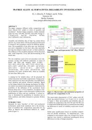
<strong>Creep</strong> corrosi<strong>on</strong> is observed <strong>on</strong> all <strong>the</strong> three types of surface f<strong>in</strong>ish based <strong>on</strong> <strong>the</strong> visual <strong>in</strong>specti<strong>on</strong> and <strong>the</strong> analysis through<br />
Cross-Secti<strong>on</strong>, SEM/EDS and electrical measurement <strong>in</strong> Table 7.<br />
Table 7. <strong>Creep</strong> corrosi<strong>on</strong> of different surface f<strong>in</strong>ishes<br />
F<strong>in</strong>ally, <strong>the</strong> corrosi<strong>on</strong> severity of <strong>the</strong> three <strong>PCB</strong> f<strong>in</strong>ishes is ranked as below.<br />
OSP > ImAg > Post-Treatment ImAg<br />
<str<strong>on</strong>g>The</str<strong>on</strong>g> creep corrosi<strong>on</strong> evoluti<strong>on</strong> of NSMD is shown <strong>in</strong> Figure 20.<br />
As orig<strong>in</strong>ally published <strong>in</strong> <strong>the</strong> <strong>IPC</strong> APEX EXPO Proceed<strong>in</strong>gs.<br />
<str<strong>on</strong>g>Surface</str<strong>on</strong>g> <str<strong>on</strong>g>F<strong>in</strong>ish</str<strong>on</strong>g> \ Result Corrosi<strong>on</strong> <strong>on</strong> pad Corrosi<strong>on</strong> <strong>on</strong> Trace Short<strong>in</strong>g Occurrence<br />
ImAg O O X<br />
Post-Treatment ImAg O X X<br />
HT OSP 1 O O O<br />
HT OSP 2 O O O
ImAg and Post-Treatment ImAg<br />
Figure 20: <strong>Creep</strong> corrosi<strong>on</strong> evoluti<strong>on</strong> of NSMD <strong>PCB</strong><br />
<str<strong>on</strong>g>The</str<strong>on</strong>g> comparis<strong>on</strong> <strong>in</strong> SEM/EDS analysis between ImAg and Post-Treatment ImAg coat<strong>in</strong>g show that <strong>the</strong> corrosi<strong>on</strong> rate of ImAg is<br />
higher than Post-Treatment ImAg. In figure 21, <strong>the</strong> corrosi<strong>on</strong> of ImAg creeps <strong>on</strong>to <strong>the</strong> trace from pad, but <strong>the</strong> corrosi<strong>on</strong> of<br />
Post-Treatment ImAg <strong>on</strong>ly occur <strong>on</strong> <strong>the</strong> pad and doesn’t creep to <strong>the</strong> trace. <str<strong>on</strong>g>The</str<strong>on</strong>g> pad of ImAg has been corroded and flaked as<br />
shown <strong>in</strong> figure 22, <strong>the</strong>refore, it is c<strong>on</strong>cluded Post-Treatment ImAg has <strong>the</strong> better performance than normal ImAg.<br />
Spectrum C O Al Si S Cu Ag Total<br />
1 15.58 76.94 7.48 100.00<br />
2 6.05 15.00 74.07 4.88 100.00<br />
3 21.78 2.31 0.78 9.72 51.40 14.00 100.00<br />
4 49.46 22.75 7.60 3.14 8.49 8.55 100.00<br />
5 23.30 11.62 59.11 5.97 100.00<br />
6 16.15 11.42 31.22 41.22 100.00<br />
7 51.55 30.08 1.17 8.08 2.32 6.80 100.00<br />
8 43.06 56.94 100.00<br />
9 48.05 51.95 100.00<br />
Max. 51.55 56.94 1.17 8.08 15.58 76.94 41.22<br />
M<strong>in</strong>. 0.00 0.00 0.00 0.00 0.00 0.00 0.00<br />
Figure 21: Top view SEM/EDS analysis<br />
As orig<strong>in</strong>ally published <strong>in</strong> <strong>the</strong> <strong>IPC</strong> APEX EXPO Proceed<strong>in</strong>gs.<br />
Spectrum C O Si S Cu Ag Total<br />
1 14.41 48.86 36.73 100.00<br />
2 14.08 62.16 23.76 100.00<br />
3 3.77 3.10 14.60 24.88 53.65 100.00<br />
4 5.63 13.53 34.90 45.94 100.00<br />
5 39.61 41.00 18.16 1.23 100.00<br />
6 42.06 44.37 13.57 100.00<br />
7 100.00 100.00<br />
Max. 42.06 100.00 18.16 14.60 62.16 53.65<br />
M<strong>in</strong>. 0.00 0.00 0.00 0.00 0.00 0.00<br />
Figure 22: Pad comparis<strong>on</strong> of side view<br />
Porosity <strong>in</strong> surface f<strong>in</strong>ish is an <strong>in</strong>herent characteristic. When <strong>the</strong> Cu pad is rougher, it will promote micro-voids. <str<strong>on</strong>g>The</str<strong>on</strong>g><br />
Post-Treatment is molecular self-assembly M<strong>on</strong>olayer. <str<strong>on</strong>g>The</str<strong>on</strong>g> molecule will selectively attach itself to available copper, as shown<br />
<strong>in</strong> Figure 23.
<str<strong>on</strong>g>The</str<strong>on</strong>g> silver layer is gett<strong>in</strong>g denser with better coverage of Cu pad prevent<strong>in</strong>g corrosi<strong>on</strong> happen<strong>in</strong>g. <str<strong>on</strong>g>The</str<strong>on</strong>g> Post-Treatment ImAg with<br />
more organic preservative is designed to have better performance than ImAg under <strong>the</strong> corrosive gas exposure. [2]<br />
<str<strong>on</strong>g>The</str<strong>on</strong>g> comparis<strong>on</strong> of <strong>the</strong> 2 HT OSP<br />
As orig<strong>in</strong>ally published <strong>in</strong> <strong>the</strong> <strong>IPC</strong> APEX EXPO Proceed<strong>in</strong>gs.<br />
Figure 23: <str<strong>on</strong>g>The</str<strong>on</strong>g> mechanism of Self-Assembly M<strong>on</strong>olayer. [2]<br />
Both HT OSP 1 and HT OSP 2 have worse performance than ImAg, but <strong>the</strong>re is not enough evidences to judge which <strong>on</strong>e is <strong>the</strong><br />
worst. HT OSP 1 has creep and flak<strong>in</strong>g corrosi<strong>on</strong>. <str<strong>on</strong>g>The</str<strong>on</strong>g> corrosi<strong>on</strong> product <strong>on</strong> <strong>the</strong> pad is th<strong>in</strong>ner and smoo<strong>the</strong>r. HT OSP 2 has<br />
creep corrosi<strong>on</strong> but <strong>the</strong> pad isn’t flaked. <str<strong>on</strong>g>The</str<strong>on</strong>g> corrosi<strong>on</strong> product <strong>on</strong> <strong>the</strong> pad of HT OSP 2 is thicker and rougher as shown <strong>in</strong><br />
Figure 24. Figure 25 shows <strong>the</strong> side view of HT OSP 1 and HT OSP 2. Both of <strong>the</strong>m have creep corrosi<strong>on</strong> from pad to <strong>the</strong> trace<br />
and <strong>the</strong> pad crater. HT OSP 2 has thicker corrosi<strong>on</strong> product <strong>on</strong> <strong>the</strong> pad.<br />
Figure 24: Top view of HT OSP1 and HT OSP2<br />
Figure 25: Both HT OSP1 and HT OSP2 have creep corrosi<strong>on</strong> product.<br />
ImAg has a higher porosity ratio than Post-Treatment ImAg and it is assumed that OSP might have higher porosity ratio than<br />
ImAg <strong>in</strong> Figure 26. Currently <strong>the</strong>re are three test<strong>in</strong>g methods for surface f<strong>in</strong>ish porosity <strong>in</strong> <strong>the</strong> <strong>in</strong>dustry. <str<strong>on</strong>g>The</str<strong>on</strong>g>se are Gas Exposure<br />
Method, Electrolysis Imag<strong>in</strong>g Method and Salt Spray Test Method. But all of <strong>the</strong>m are not <strong>the</strong> ideal and reliable test methods to<br />
identify quantitatively <strong>the</strong> porosity.
d. u-XPS Analysis<br />
As orig<strong>in</strong>ally published <strong>in</strong> <strong>the</strong> <strong>IPC</strong> APEX EXPO Proceed<strong>in</strong>gs.<br />
Figure 26: Qualitative comparis<strong>on</strong> of porosity ratio am<strong>on</strong>g surface f<strong>in</strong>ish<br />
Figure 27: Atomic Percent Profile of ImAg<br />
Figure 28: Atomic Percent Profile of Post-Treatment ImAg<br />
Figure 29: Atomic Percent Profile of HT OSP1<br />
Figure 30: Atomic Percent Profile of HT OSP2
e. Flux Residue effect <strong>on</strong> <strong>the</strong> creep corrosi<strong>on</strong> (Group B)<br />
Wave-solder<strong>in</strong>g flux residues can promote creep corrosi<strong>on</strong> and this has been published <strong>in</strong> Dr. C. Xu’s paper. [1][10] It is<br />
expected we will get a similar result <strong>in</strong> this study. <str<strong>on</strong>g>The</str<strong>on</strong>g> SEM/EDS of corroded pad with flux residue is shown <strong>in</strong> Figure 31. <str<strong>on</strong>g>The</str<strong>on</strong>g><br />
creep corrosi<strong>on</strong> is found <strong>in</strong> Figure 32 with SEM/EDS analysis. Flux residue will cause moisture absorpti<strong>on</strong> and <strong>the</strong> H+ i<strong>on</strong>ic<br />
c<strong>on</strong>tam<strong>in</strong>ati<strong>on</strong> will dissociate Cu oxide and accelerate creep corrosi<strong>on</strong>. [2]<br />
Figure 31: SEM/EDS analysis of corroded Pad<br />
Figure 32: SEM/EDS analysis of creep corrosi<strong>on</strong><br />
<strong>Creep</strong> corrosi<strong>on</strong> typically occurs when copper is exposed to an envir<strong>on</strong>ment c<strong>on</strong>ta<strong>in</strong><strong>in</strong>g sulfur. Cu2S is <strong>the</strong> primary creep<br />
corrosi<strong>on</strong> product. Cu2S is produced by <strong>the</strong> attack of <strong>the</strong> copper at <strong>the</strong> edge of <strong>the</strong> soldermask. Cu2S film can migrate across any<br />
surface that it c<strong>on</strong>tacts. <strong>Creep</strong> appears to beg<strong>in</strong> by growth of dendrites. As <strong>the</strong> corrosi<strong>on</strong> products <strong>in</strong>crease <strong>in</strong> thickness, <strong>the</strong><br />
resistance decreases until functi<strong>on</strong>al short<strong>in</strong>g occurs.<br />
C<strong>on</strong>clusi<strong>on</strong> and Fur<strong>the</strong>r Research<br />
<strong>Creep</strong> corrosi<strong>on</strong> can be driven by multiple factors. In additi<strong>on</strong> to envir<strong>on</strong>mental factors, such as polluti<strong>on</strong>, temperature, humidity<br />
<strong>the</strong> complicated <strong>PCB</strong> manufactur<strong>in</strong>g process is also ano<strong>the</strong>r c<strong>on</strong>cern. <str<strong>on</strong>g>The</str<strong>on</strong>g>re might be many potential <strong>in</strong>fluences <strong>on</strong> creep<br />
corrosi<strong>on</strong> dur<strong>in</strong>g <strong>the</strong> process and not <strong>on</strong>ly surface f<strong>in</strong>ish, flux, and board design. <str<strong>on</strong>g>The</str<strong>on</strong>g> corrosi<strong>on</strong> occurrence <strong>on</strong> <strong>the</strong> <strong>PCB</strong> is very<br />
sensitive to surface chemical properties. I<strong>on</strong>ic cleanl<strong>in</strong>ess and <strong>the</strong> roughness and surface chemistry of <strong>the</strong> soldermask might be<br />
o<strong>the</strong>r factors that <strong>in</strong>fluence <strong>the</strong> rate of creep corrosi<strong>on</strong> growth. That will be <strong>the</strong> topic for fur<strong>the</strong>r study.<br />
References<br />
As orig<strong>in</strong>ally published <strong>in</strong> <strong>the</strong> <strong>IPC</strong> APEX EXPO Proceed<strong>in</strong>gs.<br />
[1] C. Xu, W. Reents, J. Franey, J. Yaemsiri and Devaney,”<strong>Creep</strong> Corrosi<strong>on</strong> of OSP and ImAg PWB <str<strong>on</strong>g>F<strong>in</strong>ish</str<strong>on</strong>g>es” Alcatel-Lucent,<br />
Murray Hill, NJ and Raleigh, NC, USA<br />
[2] He J<strong>in</strong>gqiang, Tu Yunhua, “电子产品的爬行腐蚀失效”, Huawei Technologies Co., Ltd. EMAsia-Ch<strong>in</strong>a.com<br />
[3] He J<strong>in</strong>gqiang, Tu Yunhua, Liu Sang, ”<strong>PCB</strong> <strong>Creep</strong> Corrosi<strong>on</strong> and Board Design C<strong>on</strong>siderati<strong>on</strong>s”, Huawei Technologies Co.,<br />
Ltd. Shenzhen, Guang D<strong>on</strong>g, P.R. Ch<strong>in</strong>a<br />
[4] Craig Hillman, Joelle Arnold, Seth B<strong>in</strong>field, and Jeremy Seppi, “ SILVER AND SULFUR: CASE STUDIES, PHYSICS,<br />
AND POSSIBLE SOLUTIONS” DfR Soluti<strong>on</strong>s, College Park, MD, USA<br />
[5] American Society for Test<strong>in</strong>g and Material, ASTM Designati<strong>on</strong> B845-97: Standard Guide for Mixed Flow<strong>in</strong>g Gas (MFG)<br />
Tests for Electrical C<strong>on</strong>tacts, 1997<br />
[6] Internati<strong>on</strong>al Electro-technical Commissi<strong>on</strong>, IEC Standard 68-2-60(sec<strong>on</strong>d editi<strong>on</strong>) Envir<strong>on</strong>mental Test<strong>in</strong>g-Part2:<br />
Tests-Flow<strong>in</strong>g mixed gas corrosi<strong>on</strong> test, 1995.<br />
[7] Electr<strong>on</strong>ic Industries Associati<strong>on</strong>, EIA Standard TP-65A: Mixed Flow<strong>in</strong>g Gas, Jan. 1998
As orig<strong>in</strong>ally published <strong>in</strong> <strong>the</strong> <strong>IPC</strong> APEX EXPO Proceed<strong>in</strong>gs.<br />
[8] Telcordia GR-63-CORE Issue2, Secti<strong>on</strong> 5.5,”Airborne C<strong>on</strong>tam<strong>in</strong>ants Test Methods”, Nov. 2000<br />
[9] Chao, J.G., Gore, R.R., “Evaluati<strong>on</strong> of a mixed flow<strong>in</strong>g gas test,”1991 Proceed<strong>in</strong>gs of <strong>the</strong> Thirty Seventh IEEE Holm<br />
C<strong>on</strong>ference <strong>on</strong> Electrical C<strong>on</strong>tacts,pp.216-228, Piscataway, NJ:IEEE,1991.<br />
[10] C. Xu, W. Reents, J. Franey, J. Yaemsiri and J. Devaney,”<strong>Creep</strong> Corrosi<strong>on</strong> of OSP and ImAg PWB <str<strong>on</strong>g>F<strong>in</strong>ish</str<strong>on</strong>g>es”,<br />
Alcatel-Lucent, Murray Hill, NJ and Raleigh, NC, USA<br />
[11] Coulometeric Reducti<strong>on</strong> data is c<strong>on</strong>ducted by IBM’s Dr. PJ S<strong>in</strong>gh <strong>in</strong> INEMI <strong>Creep</strong> Corrosi<strong>on</strong> project<br />
[12] Lenora Toscano, Ernest L<strong>on</strong>g, Ph.D., and Swans<strong>on</strong>,”CREEP CORROSION ON <strong>PCB</strong> SURFACES: IMPROVEMENTS OF<br />
PREDICTIVE TEST METHODS ANDDEVELOPMENTS REGARDING PREVENTION TECHNIQUES”, Mac Dermid,<br />
Waterbury, CT,USA<br />
[13] Randy Schueller, Ph.D, ”CREEP CORROSION ON LEAD-FREE PRINTED CIRCUIT BOARDS IN HIGH SULFUR<br />
ENVIRONMENTS”, Dell Inc. Aust<strong>in</strong>, TX, USA
As orig<strong>in</strong>ally published <strong>in</strong> <strong>the</strong> <strong>IPC</strong> APEX EXPO Proceed<strong>in</strong>gs.<br />
<str<strong>on</strong>g>The</str<strong>on</strong>g> <str<strong>on</strong>g>Surface</str<strong>on</strong>g> <str<strong>on</strong>g>F<strong>in</strong>ish</str<strong>on</strong>g> <str<strong>on</strong>g>Effect</str<strong>on</strong>g> <strong>on</strong> <strong>the</strong> <strong>Creep</strong> Corrosi<strong>on</strong> <strong>in</strong> <strong>PCB</strong><br />
Presenter : Cherie Chen
• Introducti<strong>on</strong><br />
• Experiment Purpose<br />
• Experiment Design<br />
• Experiment Result<br />
• C<strong>on</strong>clusi<strong>on</strong><br />
• Q & A<br />
As orig<strong>in</strong>ally published <strong>in</strong> <strong>the</strong> <strong>IPC</strong> APEX EXPO Proceed<strong>in</strong>gs.<br />
Outl<strong>in</strong>e
As orig<strong>in</strong>ally published <strong>in</strong> <strong>the</strong> <strong>IPC</strong> APEX EXPO Proceed<strong>in</strong>gs.<br />
Introducti<strong>on</strong>
• Pacific R<strong>in</strong>g of Fire<br />
• East Africa R<strong>in</strong>g of Fire<br />
• Mediterranean R<strong>in</strong>g of Fire<br />
• Java R<strong>in</strong>g of Fire<br />
As orig<strong>in</strong>ally published <strong>in</strong> <strong>the</strong> <strong>IPC</strong> APEX EXPO Proceed<strong>in</strong>gs.<br />
<str<strong>on</strong>g>The</str<strong>on</strong>g> Major Volcanic Belts <strong>in</strong> <str<strong>on</strong>g>The</str<strong>on</strong>g> World<br />
Refer to :新竹市青草湖社区大学网站
Frequent Volcanic Erupti<strong>on</strong>s <strong>in</strong> Recent Years<br />
Volcanic Erupti<strong>on</strong>s <strong>in</strong> 2010 ~ 2011<br />
Time Volcano Area<br />
2010.03 Eyjafjallajokull Volcano Ice Island<br />
2010.10 Merapi Volcano Ind<strong>on</strong>esia<br />
2011.01 Mount Etha Volcano Italy<br />
2011.02 Bulusan Volcano Philipp<strong>in</strong>es<br />
2011.03 Kilauea Volcano Hawaii<br />
2011.03 Sh<strong>in</strong>moedake Volcano Japan<br />
2011.03 Kagoshima Volcano Japan<br />
? Mount Changbai Volcano Ch<strong>in</strong>a<br />
? Mount Tatun Volcano Taiwan<br />
As orig<strong>in</strong>ally published <strong>in</strong> <strong>the</strong> <strong>IPC</strong> APEX EXPO Proceed<strong>in</strong>gs.<br />
Geological experts say :<br />
• 20 Volcanic Erupti<strong>on</strong>s<br />
any time<br />
• Volcanic Activities occur<br />
more frequently s<strong>in</strong>ce<br />
2000.<br />
Italy Vesuvius Volcanic Erupti<strong>on</strong>s Crater of Mount Vesuvius
As orig<strong>in</strong>ally published <strong>in</strong> <strong>the</strong> <strong>IPC</strong> APEX EXPO Proceed<strong>in</strong>gs.<br />
<str<strong>on</strong>g>The</str<strong>on</strong>g> Silent Mount Before Volcanic Erupti<strong>on</strong>s<br />
Mount Changbai <strong>in</strong> Ch<strong>in</strong>a Mount Tatun <strong>in</strong> Taiwan<br />
refer to : http://chifoto.blogspot.com/<br />
取自新华网
Reuni<strong>on</strong> Volcano<br />
Alaska Volcano<br />
As orig<strong>in</strong>ally published <strong>in</strong> <strong>the</strong> <strong>IPC</strong> APEX EXPO Proceed<strong>in</strong>gs.<br />
Volcanic Erupti<strong>on</strong>s<br />
Refer to 新华网 Refer 取自新华网 to 中广网<br />
Refer to 新华网<br />
Ice Island Volcano<br />
World Geological Park –Mount Yandang<br />
Refer to 世界地质公园网络办公室
<str<strong>on</strong>g>The</str<strong>on</strong>g> Product of Volcanic Erupti<strong>on</strong>s ~ Ash<br />
• Diameter is less than 2mm<br />
• Composed of <strong>the</strong> rocks, m<strong>in</strong>erals and volcanic glass fragments<br />
• From <strong>the</strong> rock and magma crushed <strong>in</strong>to small particles dur<strong>in</strong>g <strong>the</strong><br />
volcanic erupti<strong>on</strong>s<br />
• Different from <strong>the</strong> soot,hard and <strong>in</strong>soluble <strong>in</strong> water<br />
• In additi<strong>on</strong> to <strong>the</strong> climate impact of volcanic ash, but also <strong>on</strong> human<br />
and animal damage to <strong>the</strong> respiratory system<br />
取自Nati<strong>on</strong>al Geographic<br />
As orig<strong>in</strong>ally published <strong>in</strong> <strong>the</strong> <strong>IPC</strong> APEX EXPO Proceed<strong>in</strong>gs.
As orig<strong>in</strong>ally published <strong>in</strong> <strong>the</strong> <strong>IPC</strong> APEX EXPO Proceed<strong>in</strong>gs.<br />
<str<strong>on</strong>g>The</str<strong>on</strong>g> comparis<strong>on</strong> of general and volcanic gas compositi<strong>on</strong>s<br />
General Gas Compositi<strong>on</strong> Volcanic Gas Compositi<strong>on</strong><br />
<str<strong>on</strong>g>The</str<strong>on</strong>g> general gas compositi<strong>on</strong> and volcanic gas compositi<strong>on</strong> are closely<br />
related to exhaust gas of volcanic erupti<strong>on</strong>s.<br />
Refer to 台湾台北科技大学网站
<strong>Creep</strong> Corrosi<strong>on</strong><br />
• <strong>Creep</strong> corrosi<strong>on</strong> typically occurs when copper is exposed to an<br />
envir<strong>on</strong>ment c<strong>on</strong>ta<strong>in</strong><strong>in</strong>g sulfur.<br />
•Cu 2S is <strong>the</strong> primary creep corrosi<strong>on</strong> product. Cu 2S is produced by <strong>the</strong><br />
attack of <strong>the</strong> copper at <strong>the</strong> edge of <strong>the</strong> soldermask.<br />
•<strong>Creep</strong> appears to beg<strong>in</strong> by growth of dendrites. As <strong>the</strong> corrosi<strong>on</strong><br />
products <strong>in</strong>crease <strong>in</strong> thickness, <strong>the</strong> resistance decreases until<br />
functi<strong>on</strong>al short<strong>in</strong>g occurs.<br />
<strong>Creep</strong> Corrosi<strong>on</strong> <strong>on</strong> <strong>PCB</strong> <strong>Creep</strong> Corrosi<strong>on</strong> <strong>on</strong> PPF SOIC<br />
Refer to : Dr. Randy Schueller’s published paper<br />
As orig<strong>in</strong>ally published <strong>in</strong> <strong>the</strong> <strong>IPC</strong> APEX EXPO Proceed<strong>in</strong>gs.<br />
Refer to : <strong>the</strong> published paper of Maryland University
Comparis<strong>on</strong> am<strong>on</strong>g <strong>Creep</strong> Corrosi<strong>on</strong>, Dendrite and CAF<br />
Comparis<strong>on</strong><br />
<strong>Creep</strong><br />
Corrosi<strong>on</strong><br />
Dendrite CAF<br />
Substrate Cu Cu/Ag/T<strong>in</strong>-<br />
Lead…<br />
Cu<br />
Corrosi<strong>on</strong><br />
Product<br />
Cu2S<br />
FO Cu Oxide/<br />
Hydroxide<br />
Electr<strong>on</strong> X Cathode to Anode to<br />
Migrati<strong>on</strong><br />
Anode Cathode<br />
Failure Mode Short /<br />
Open<br />
Short Short<br />
Humidity<br />
Requirement<br />
Yes Yes Yes<br />
Voltage<br />
Requirement<br />
No Yes Yes<br />
CAF<br />
As orig<strong>in</strong>ally published <strong>in</strong> <strong>the</strong> <strong>IPC</strong> APEX EXPO Proceed<strong>in</strong>gs.<br />
Refer to 中国赛宝实验室可靠性分析中心<br />
<strong>Creep</strong> Corrosi<strong>on</strong><br />
Dendrite<br />
Refer to 北京工业大学现代教育技术中心
As orig<strong>in</strong>ally published <strong>in</strong> <strong>the</strong> <strong>IPC</strong> APEX EXPO Proceed<strong>in</strong>gs.<br />
<str<strong>on</strong>g>The</str<strong>on</strong>g> Mechanism of <strong>Creep</strong> Corrosi<strong>on</strong><br />
<str<strong>on</strong>g>The</str<strong>on</strong>g> mechanism of creep corrosi<strong>on</strong> <strong>in</strong> Dr. P<strong>in</strong>g Zhao’s previous published<br />
paper described <strong>the</strong> process of Dissoluti<strong>on</strong> → Diffusi<strong>on</strong> → Re-depositi<strong>on</strong><br />
<strong>Creep</strong> Corrosi<strong>on</strong> <strong>on</strong> <strong>the</strong> Gull-W<strong>in</strong>g Lead of PSOP 1. <str<strong>on</strong>g>The</str<strong>on</strong>g> multiple m<strong>on</strong>olayers<br />
of water are<br />
adsorbed <strong>on</strong> <strong>the</strong><br />
surface under high<br />
relative humidity and<br />
<strong>the</strong>n <strong>the</strong> corrosi<strong>on</strong><br />
products dissolve <strong>in</strong>to<br />
<strong>the</strong>se water layers.<br />
2. <str<strong>on</strong>g>The</str<strong>on</strong>g>y diffuse over <strong>the</strong><br />
surface <strong>in</strong> soluti<strong>on</strong><br />
down <strong>the</strong> c<strong>on</strong>centrati<strong>on</strong><br />
gradient and redeposit.
<str<strong>on</strong>g>The</str<strong>on</strong>g> Factors to <strong>Creep</strong> Corrosi<strong>on</strong><br />
<strong>PCB</strong> Design<br />
SMD & NSMD<br />
Reflow<br />
As orig<strong>in</strong>ally published <strong>in</strong> <strong>the</strong> <strong>IPC</strong> APEX EXPO Proceed<strong>in</strong>gs.<br />
<str<strong>on</strong>g>Surface</str<strong>on</strong>g><br />
<str<strong>on</strong>g>F<strong>in</strong>ish</str<strong>on</strong>g><br />
Test<br />
C<strong>on</strong>diti<strong>on</strong><br />
Wave<br />
Solder<strong>in</strong>g<br />
Flux Residue<br />
Solder Paste<br />
Coverage
As orig<strong>in</strong>ally published <strong>in</strong> <strong>the</strong> <strong>IPC</strong> APEX EXPO Proceed<strong>in</strong>gs.<br />
MFG Test
As orig<strong>in</strong>ally published <strong>in</strong> <strong>the</strong> <strong>IPC</strong> APEX EXPO Proceed<strong>in</strong>gs.<br />
• <str<strong>on</strong>g>The</str<strong>on</strong>g> MFG test method was carried out <strong>in</strong><br />
1980’s.<br />
• A laboratory test where <strong>the</strong> temperature (�),<br />
relative humidity (%RH), c<strong>on</strong>centrati<strong>on</strong> of<br />
gaseous pollutants (ppb level), and o<strong>the</strong>r critical<br />
variables (such as volume exchange rate and<br />
airflow rate) are carefully def<strong>in</strong>ed, m<strong>on</strong>itored<br />
and c<strong>on</strong>trolled.<br />
• <str<strong>on</strong>g>The</str<strong>on</strong>g> purpose of MFG test is to use <strong>the</strong><br />
comb<strong>in</strong>ati<strong>on</strong> of four most comm<strong>on</strong> corrosive<br />
gases <strong>in</strong> <strong>the</strong> envir<strong>on</strong>ment, H 2S, Cl 2, NO 2, SO 2 to<br />
simulate and accelerate atmospheric corrosi<strong>on</strong><br />
due to exposure.<br />
• Many specific and applicati<strong>on</strong>-oriented MFG<br />
test methods created for <strong>in</strong>dustrial applicati<strong>on</strong>s<br />
• <str<strong>on</strong>g>The</str<strong>on</strong>g>re is still no accepted <strong>in</strong>dustry standard<br />
created for MFG test to correlate to real service<br />
life yet.<br />
MFG(Mixed Flow<strong>in</strong>g Gas) Test<br />
Applicati<strong>on</strong>-oriented MFG test methods
Brand : Yamasaki<br />
Model : GH-180-VL/M(Japan)<br />
Temperature : 20 � ±50 �<br />
Humidity Range : 70 ~ 95%(RH)<br />
Exchange Rate : 1500 L / hour<br />
Mode : S<strong>in</strong>gle or Mixed flow<strong>in</strong>g gas<br />
Inside Dimensi<strong>on</strong> :<br />
50 cm (W) x 50 cm (D) x 50 cm (H)<br />
As orig<strong>in</strong>ally published <strong>in</strong> <strong>the</strong> <strong>IPC</strong> APEX EXPO Proceed<strong>in</strong>gs.<br />
MFG Test System<br />
MFG Test System MFG Test Flow
As orig<strong>in</strong>ally published <strong>in</strong> <strong>the</strong> <strong>IPC</strong> APEX EXPO Proceed<strong>in</strong>gs.<br />
Test C<strong>on</strong>diti<strong>on</strong>s & Gas C<strong>on</strong>centrati<strong>on</strong> Sett<strong>in</strong>g<br />
H2S NO2 Cl2 SO2 Temp. RH Durati<strong>on</strong>(day)<br />
1700 ppb 200ppb 20ppb 200ppb 40� 90% 21<br />
• Gas c<strong>on</strong>centrati<strong>on</strong> is set accord<strong>in</strong>g to <strong>the</strong> exchange rate of <strong>the</strong> chamber<br />
•1500 Litter gas get <strong>in</strong>to <strong>the</strong> chamber and 1500 Little gas emissi<strong>on</strong> go out<br />
Gas C<strong>on</strong>centrati<strong>on</strong><br />
Test C<strong>on</strong>diti<strong>on</strong><br />
Gas H2S Cl2 SO2 NO2<br />
C<strong>on</strong>centrati<strong>on</strong> 1700 ppb 20 ppb 200 ppb 200 ppb<br />
Gas Cyl<strong>in</strong>der 50000 ppm 100 ppm 1000 ppm 1000 ppm<br />
Chamber Exchange Rate<br />
1500 L/H<br />
Liter/per hour (L/H) 0.05 0.3 0.3 0.3<br />
Calculati<strong>on</strong> of Exchange Rate<br />
Gas<br />
H2S<br />
Cl2<br />
SO2<br />
NO2<br />
Gas In = Gas Out<br />
1500 L/H x 1.7 ppm<br />
1500 L/H x 0.02 ppm<br />
1500 L/H x 0.2 ppm<br />
1500 L/H x 0.2 ppm<br />
0.05 L/H x 50000 ppm<br />
0.3 L/H x 100 ppm<br />
0.3 L/H x 1000 ppm<br />
0.3 L/H x 1000 ppm
As orig<strong>in</strong>ally published <strong>in</strong> <strong>the</strong> <strong>IPC</strong> APEX EXPO Proceed<strong>in</strong>gs.<br />
Uniformity Measurement <strong>in</strong> <strong>the</strong> MFG chamber
As orig<strong>in</strong>ally published <strong>in</strong> <strong>the</strong> <strong>IPC</strong> APEX EXPO Proceed<strong>in</strong>gs.<br />
Chamber Set up of Uniformity Test<br />
Test C<strong>on</strong>diti<strong>on</strong><br />
H2S NO2 Cl2 SO2 Temp. RH Durati<strong>on</strong>(day)<br />
500/1000/1700 ppb 200ppb 20ppb 200ppb 40� 75% 5
Weight Ga<strong>in</strong> Analysis<br />
Ag Coup<strong>on</strong> Ag1 Ag2 Ag3 Ag4 Ag5<br />
Ag2S wt ga<strong>in</strong> (angstroms) 630 910 580 1170 720<br />
Ag2S CR (angstroms) 513 538 535 546 636<br />
Cu Coup<strong>on</strong> Cu1 Cu2 Cu3 Cu4 Cu5<br />
Cu corrosi<strong>on</strong> product wt ga<strong>in</strong> (angstroms) 15880 15630 15060 17840 17790<br />
CR (angstroms) 14603 20361 14127 20547 16574<br />
• Weight ga<strong>in</strong> analysis methods :<br />
a. Weight Measurement<br />
b. Coulometric Reducti<strong>on</strong>(CR)<br />
c. X-Secti<strong>on</strong> with SEM/EDS<br />
•<str<strong>on</strong>g>The</str<strong>on</strong>g> data of weight ga<strong>in</strong> analysis<br />
by <strong>the</strong> three methods are<br />
c<strong>on</strong>sistent to each o<strong>the</strong>r.<br />
As orig<strong>in</strong>ally published <strong>in</strong> <strong>the</strong> <strong>IPC</strong> APEX EXPO Proceed<strong>in</strong>gs.
As orig<strong>in</strong>ally published <strong>in</strong> <strong>the</strong> <strong>IPC</strong> APEX EXPO Proceed<strong>in</strong>gs.<br />
Weight ga<strong>in</strong> Analysis of Cu/Ag coup<strong>on</strong>s <strong>in</strong> 3 different c<strong>on</strong>centrati<strong>on</strong> of H 2S<br />
• <str<strong>on</strong>g>The</str<strong>on</strong>g> corrosi<strong>on</strong> rate of Cu coup<strong>on</strong> rapidly <strong>in</strong>creases while H 2S c<strong>on</strong>centrati<strong>on</strong> after reach<strong>in</strong>g at<br />
1000 ppb.<br />
• Ag coup<strong>on</strong> has more active performance <strong>in</strong> lower H 2S c<strong>on</strong>centrati<strong>on</strong> than higher H 2S<br />
c<strong>on</strong>centrati<strong>on</strong>.<br />
• Flak<strong>in</strong>g corrosi<strong>on</strong> also happens <strong>on</strong> <strong>the</strong> Cu coup<strong>on</strong> with heavy corrosi<strong>on</strong> product <strong>in</strong> <strong>the</strong> high<br />
H 2S c<strong>on</strong>centrati<strong>on</strong> test c<strong>on</strong>diti<strong>on</strong>.
As orig<strong>in</strong>ally published <strong>in</strong> <strong>the</strong> <strong>IPC</strong> APEX EXPO Proceed<strong>in</strong>gs.<br />
MFG Test Matrix<br />
Group Test Vehicle Feature Factors to study<br />
<str<strong>on</strong>g>Surface</str<strong>on</strong>g> <str<strong>on</strong>g>F<strong>in</strong>ish</str<strong>on</strong>g><br />
1) ImAg<br />
A HF <strong>PCB</strong> 80 x 80 mm NSMD 2) Post-Treatment ImAg<br />
3) HT OSP1<br />
4) HT OSP2<br />
SMD<br />
Flux<br />
B HF <strong>PCB</strong> 80 x 80 mm<br />
Comb L<strong>in</strong>e<br />
1) NC OA Flux1<br />
2) NC OA Flux2<br />
• To <strong>in</strong>vestigate material, process and design effect <strong>on</strong><br />
<strong>the</strong> creep corrosi<strong>on</strong>.<br />
• Two groups( A and B) of test boards are <strong>in</strong>vestigated<br />
<strong>in</strong> this study.
<strong>PCB</strong> Design & <str<strong>on</strong>g>Surface</str<strong>on</strong>g> <str<strong>on</strong>g>F<strong>in</strong>ish</str<strong>on</strong>g><br />
Group A Group B<br />
SMD Design<br />
SMD & NSMD Design<br />
As orig<strong>in</strong>ally published <strong>in</strong> <strong>the</strong> <strong>IPC</strong> APEX EXPO Proceed<strong>in</strong>gs.<br />
NSMD Design<br />
Group <str<strong>on</strong>g>Surface</str<strong>on</strong>g> <str<strong>on</strong>g>F<strong>in</strong>ish</str<strong>on</strong>g> Supplier<br />
Group A<br />
ImAg Supplier 1<br />
Post-Treatment ImAg Supplier 2<br />
HT OSP 1 Supplier 3<br />
HT OSP 2 Supplierr 2<br />
Group B ImAg Supplier 1
• Group B<br />
Flux Residue for Wave Solder<strong>in</strong>g Simulati<strong>on</strong><br />
• Spray 2 different types of NC OA Flux <strong>on</strong> <strong>the</strong> boards<br />
• <str<strong>on</strong>g>The</str<strong>on</strong>g> boards with flux are baked at 125� for 5 m<strong>in</strong>utes and <strong>the</strong>n 270� for 1<br />
m<strong>in</strong>ute to simulate <strong>the</strong> wave solder<strong>in</strong>g process.<br />
NC OA<br />
Flux 1<br />
NC OA<br />
Flux 2<br />
As orig<strong>in</strong>ally published <strong>in</strong> <strong>the</strong> <strong>IPC</strong> APEX EXPO Proceed<strong>in</strong>gs.<br />
Bak<strong>in</strong>g
• Test C<strong>on</strong>diti<strong>on</strong>s:<br />
MFG Test<br />
• All test boards have <strong>on</strong>e time reflow before MFG test<br />
SMT l<strong>in</strong>e & Reflow Profile<br />
As orig<strong>in</strong>ally published <strong>in</strong> <strong>the</strong> <strong>IPC</strong> APEX EXPO Proceed<strong>in</strong>gs.<br />
Chamber set up
As orig<strong>in</strong>ally published <strong>in</strong> <strong>the</strong> <strong>IPC</strong> APEX EXPO Proceed<strong>in</strong>gs.<br />
Experiment Result
As orig<strong>in</strong>ally published <strong>in</strong> <strong>the</strong> <strong>IPC</strong> APEX EXPO Proceed<strong>in</strong>gs.<br />
SMD vs NSMD Effec <strong>on</strong> <strong>Creep</strong> Corrosi<strong>on</strong><br />
• <str<strong>on</strong>g>The</str<strong>on</strong>g> degree of creep corrosi<strong>on</strong> <strong>on</strong> SMD board feature grows laterally<br />
across solder mask is greater than that at <strong>the</strong> metal/lam<strong>in</strong>ate <strong>in</strong>terface<br />
<strong>on</strong> NSMD board feature.<br />
• <str<strong>on</strong>g>The</str<strong>on</strong>g> difference is expla<strong>in</strong>ed as follow<strong>in</strong>g discussi<strong>on</strong> :<br />
1) <str<strong>on</strong>g>The</str<strong>on</strong>g> migrati<strong>on</strong> <strong>on</strong> <strong>the</strong> lam<strong>in</strong>ate around NSMD areas has to overcome<br />
<strong>the</strong> land between Cu pad and solder mask.<br />
2) SMD is a much smoo<strong>the</strong>r surface so that <strong>the</strong> corrosi<strong>on</strong> product can<br />
travel much more readily across <strong>the</strong> planar surface.<br />
3) A gap is made at <strong>the</strong> <strong>in</strong>terface between soldermask and Cu pad due to<br />
<strong>the</strong> poor soldermask process<strong>in</strong>g (exposed Cu at edge of soldermask),<br />
so that creep corrosi<strong>on</strong> emanate from SMD features.
SMD vs NSMD Effec <strong>on</strong> <strong>Creep</strong> Corrosi<strong>on</strong><br />
Perfect & Normal soldermask process<strong>in</strong>g<br />
<strong>Creep</strong> Corrosi<strong>on</strong> evoluti<strong>on</strong> of SMD & NSMD <strong>PCB</strong><br />
As orig<strong>in</strong>ally published <strong>in</strong> <strong>the</strong> <strong>IPC</strong> APEX EXPO Proceed<strong>in</strong>gs.<br />
<strong>Creep</strong> Corrosi<strong>on</strong> occurred from <strong>the</strong> exposed copper at <strong>the</strong> edge of soldermask<br />
<strong>PCB</strong> <strong>Creep</strong> Corrosi<strong>on</strong> of SMD & NSMD <strong>PCB</strong>
As orig<strong>in</strong>ally published <strong>in</strong> <strong>the</strong> <strong>IPC</strong> APEX EXPO Proceed<strong>in</strong>gs.<br />
<str<strong>on</strong>g>Surface</str<strong>on</strong>g> <str<strong>on</strong>g>F<strong>in</strong>ish</str<strong>on</strong>g> <str<strong>on</strong>g>Effect</str<strong>on</strong>g> <strong>on</strong> <strong>Creep</strong> Corrosi<strong>on</strong>– Group A<br />
• <strong>Creep</strong> corrosi<strong>on</strong> is observed <strong>on</strong> all <strong>the</strong> three types of surface f<strong>in</strong>ish based <strong>on</strong><br />
<strong>the</strong> visual <strong>in</strong>specti<strong>on</strong> and <strong>the</strong> analysis through Cross-Secti<strong>on</strong>, SEM/EDS and<br />
electrical measurement. <str<strong>on</strong>g>The</str<strong>on</strong>g> result show as below.<br />
<str<strong>on</strong>g>Surface</str<strong>on</strong>g> <str<strong>on</strong>g>F<strong>in</strong>ish</str<strong>on</strong>g> \ Result Corrosi<strong>on</strong> <strong>on</strong> pad Corrosi<strong>on</strong> <strong>on</strong> Trace <strong>Creep</strong> Corrosi<strong>on</strong> Short<strong>in</strong>g Occurrence Rank<br />
ImAg O O O X 2<br />
Post-Treatment ImAg O X O X 3<br />
HT OSP 1<br />
HT OSP 2<br />
O<br />
O<br />
O<br />
O<br />
O<br />
O<br />
O<br />
O<br />
1<br />
• <str<strong>on</strong>g>The</str<strong>on</strong>g> corrosi<strong>on</strong> severity of <strong>the</strong> three <strong>PCB</strong> surface f<strong>in</strong>ishes is ranked as below.<br />
OSP > ImAg > Post-Treatment ImAg
As orig<strong>in</strong>ally published <strong>in</strong> <strong>the</strong> <strong>IPC</strong> APEX EXPO Proceed<strong>in</strong>gs.<br />
ImAg and Post-Treatment ImAg<br />
Refer to EMAsia-Ch<strong>in</strong>a.com<br />
Post-Treatment is molecular self-assembly<br />
M<strong>on</strong>olayer. <str<strong>on</strong>g>The</str<strong>on</strong>g> molecule will selectively<br />
attach itself to available copper. <str<strong>on</strong>g>The</str<strong>on</strong>g> silver<br />
layer is gett<strong>in</strong>g denser with better coverage<br />
of Cu pad to prevent corrosi<strong>on</strong> happen<strong>in</strong>g.<br />
<str<strong>on</strong>g>The</str<strong>on</strong>g> Post-Treatment ImAg with more<br />
organic preservative is designed to have<br />
better performance than ImAg under <strong>the</strong><br />
corrosive gas exposure.
As orig<strong>in</strong>ally published <strong>in</strong> <strong>the</strong> <strong>IPC</strong> APEX EXPO Proceed<strong>in</strong>gs.<br />
<str<strong>on</strong>g>The</str<strong>on</strong>g> Comparis<strong>on</strong> of HT OSP1 & HT OSP2<br />
• Both HT OSP 1 and HT OSP 2 have worse performance than ImAg, but <strong>the</strong>re are<br />
no enough evidences to judge which <strong>on</strong>e is <strong>the</strong> worst.<br />
• HT OSP 1 has creep and flak<strong>in</strong>g corrosi<strong>on</strong>. <str<strong>on</strong>g>The</str<strong>on</strong>g> corrosi<strong>on</strong> product <strong>on</strong> <strong>the</strong> pad is<br />
th<strong>in</strong>ner and smoo<strong>the</strong>r.<br />
• HT OSP 2 has creep corrosi<strong>on</strong> but <strong>the</strong> pad isn’t flaked. <str<strong>on</strong>g>The</str<strong>on</strong>g> corrosi<strong>on</strong> product <strong>on</strong><br />
<strong>the</strong> pad of HT OSP 2 is thicker and rougher.<br />
• Both of <strong>the</strong>m have creep corrosi<strong>on</strong> from pad<br />
to <strong>the</strong> trace and <strong>the</strong> pad crater. HT OSP 2<br />
has thicker corrosi<strong>on</strong> product <strong>on</strong> <strong>the</strong> pad.
As orig<strong>in</strong>ally published <strong>in</strong> <strong>the</strong> <strong>IPC</strong> APEX EXPO Proceed<strong>in</strong>gs.<br />
Qualitative Comparis<strong>on</strong> of Porosity Ratio Am<strong>on</strong>g <str<strong>on</strong>g>Surface</str<strong>on</strong>g> <str<strong>on</strong>g>F<strong>in</strong>ish</str<strong>on</strong>g>es<br />
• ImAg has <strong>the</strong> higher porosity ratio than Post-Treatment ImAg, it is<br />
assumed that OSP might have higher porosity ratio than ImAg.<br />
• In Currently <strong>the</strong>re are three test<strong>in</strong>g methods for surface f<strong>in</strong>ish<br />
porosity test <strong>in</strong> <strong>the</strong> <strong>in</strong>dustry, which are Gas Exposure Method,<br />
Electrolysis Imag<strong>in</strong>g Method and Salt Spray Test Method.<br />
But all of <strong>the</strong>m are not <strong>the</strong> ideal and reliable test methods to identify<br />
quantitatively <strong>the</strong> porosity.
As orig<strong>in</strong>ally published <strong>in</strong> <strong>the</strong> <strong>IPC</strong> APEX EXPO Proceed<strong>in</strong>gs.<br />
u-XPS Analysis<br />
ImAg vs Post-Treatment ImAg<br />
HT OSP1 vs HT OSP2
As orig<strong>in</strong>ally published <strong>in</strong> <strong>the</strong> <strong>IPC</strong> APEX EXPO Proceed<strong>in</strong>gs.<br />
Flux Residue effect <strong>on</strong> <strong>the</strong> creep corrosi<strong>on</strong> – Group B<br />
• Flux residue will cause easily moisture absorpti<strong>on</strong> and <strong>the</strong> H+ of i<strong>on</strong><br />
c<strong>on</strong>tam<strong>in</strong>ati<strong>on</strong> is helpful to dissociate Cu oxide and accelerate creep<br />
corrosi<strong>on</strong>.
As orig<strong>in</strong>ally published <strong>in</strong> <strong>the</strong> <strong>IPC</strong> APEX EXPO Proceed<strong>in</strong>gs.<br />
C<strong>on</strong>clusi<strong>on</strong>s<br />
• <strong>Creep</strong> corrosi<strong>on</strong> can be driven by multiple factors.<br />
• Except envir<strong>on</strong>mental factors, such as polluti<strong>on</strong>, temperature,<br />
humidity, complicated <strong>PCB</strong> manufactur<strong>in</strong>g process is ano<strong>the</strong>r<br />
c<strong>on</strong>cern.<br />
• <str<strong>on</strong>g>The</str<strong>on</strong>g>re might be many potential <strong>in</strong>fluences to creep corrosi<strong>on</strong><br />
dur<strong>in</strong>g <strong>the</strong> process not <strong>on</strong>ly surface f<strong>in</strong>ish, flux, and board design.<br />
• <str<strong>on</strong>g>The</str<strong>on</strong>g> corrosi<strong>on</strong> occurrence <strong>on</strong> <strong>PCB</strong> is very sensitive to surface<br />
chemical properties. I<strong>on</strong>ic cleanl<strong>in</strong>ess, <strong>the</strong> roughness and surface<br />
chemistry of <strong>the</strong> soldermask might be o<strong>the</strong>r factors to <strong>in</strong>fluence<br />
<strong>the</strong> rate of creep corrosi<strong>on</strong> growth.
As orig<strong>in</strong>ally published <strong>in</strong> <strong>the</strong> <strong>IPC</strong> APEX EXPO Proceed<strong>in</strong>gs.<br />
Welcome your comments !