Corn Sweetener Refining With Ion Exchange Resins - Purolite
Corn Sweetener Refining With Ion Exchange Resins - Purolite
Corn Sweetener Refining With Ion Exchange Resins - Purolite

You also want an ePaper? Increase the reach of your titles
YUMPU automatically turns print PDFs into web optimized ePapers that Google loves.
<strong>Corn</strong> <strong>Sweetener</strong> <strong>Refining</strong><br />
with <strong>Ion</strong> <strong>Exchange</strong> <strong>Resins</strong><br />
Just ask <strong>Purolite</strong>.<br />
®
Table of Contents<br />
Introduction<br />
<strong>Corn</strong> <strong>Sweetener</strong> <strong>Refining</strong> Overview 2<br />
Demineralization 3<br />
Chromatographic Separation 3<br />
Polishing 3<br />
Resin Structure 4<br />
Unit Operation Process Design<br />
Demineralization Process 5<br />
Demineralization Equipment 8<br />
Separation Process 9<br />
Separation Equipment 11<br />
Polishing Process 13<br />
Mixed Bed Polisher Equipment 15<br />
<strong>Ion</strong> <strong>Exchange</strong> <strong>Resins</strong><br />
Resin Specifications 16<br />
Higher Performance Weak Base Anion Resin 18<br />
Life Expectancy 18<br />
Degradation 19<br />
Troubleshooting 21<br />
Macronet Adsorbent <strong>Resins</strong> 22<br />
<strong>Purolite</strong><br />
About Us 24<br />
Photographs<br />
ICP and AA Spectrophotometers 26<br />
ICP Spectrophotometer 26<br />
Bench Scale Studies 26<br />
Microscopic Resin Evaluation 27<br />
Gel <strong>Ion</strong> <strong>Exchange</strong> Resin 27<br />
Macroporous <strong>Ion</strong> <strong>Exchange</strong> Resin 27<br />
V mixer 28<br />
Bulk Tanker Truck Resin Delivery 28<br />
Packaging Options 28<br />
1<br />
C ORN SWEETENER REFINING WITH ION EXC HANGE RESINS<br />
Figures<br />
A. Typical Service Cycle 29<br />
B. Cation Leakage 29<br />
C. Anion Leakage 29<br />
D. Sweeten-Off 30<br />
E. Sweeten-On 30<br />
F. Cation Operating Capacity 30<br />
G. Conductivity vs. Concentration 30<br />
H. C-150S Backwash Expansion 31<br />
I. A-103S Backwash Expansion 31<br />
J. A-103S Pressure Drop 31<br />
K. C-150S Pressure Drop 31<br />
L. High Capacity Weak Base Anion<br />
Resin Comparison 32<br />
Tables<br />
A. Conductance vs.Total Dissolved Solids 33<br />
B. Conversions 33<br />
C. Physical Constants of 55% High<br />
Fructose <strong>Corn</strong> Syrup 36<br />
D. Concentration of Regenerants 38<br />
E. Calcium Carbonate Equivalents 41<br />
F. Acid and Caustic Concentration vs. pH 42<br />
G. Tank Capacities 42<br />
H. Mesh and Slot Sizes 43<br />
I. Relative <strong>Ion</strong> Selectivities 43<br />
J. Regenerant Chemicals Specifications 44<br />
K. Specifications for HFCS-55 45<br />
Procedures<br />
A. ICUMSA Method for Color Measurement 46<br />
B. Cleaning of Organically Fouled<br />
Anion <strong>Resins</strong> 47<br />
C. FDA Conditioning of <strong>Ion</strong> <strong>Exchange</strong> Resin<br />
Before Food Use 48<br />
D. Method for Backwashed and Settled<br />
Resin Density 49<br />
E. Particle Size Distribution<br />
(Uniformity Coefficient) 50<br />
F. Determination of Acidity 50<br />
G. Glossary 51
Introduction<br />
C ORN SWEETENER REFINING WITH ION EXC HANGE RESINS<br />
<strong>Corn</strong> <strong>Sweetener</strong> <strong>Refining</strong> Overview<br />
Liquid and solid sweeteners are produced around the world from several starch sources<br />
including corn, wheat, tapioca, potatoes and even cellulose hydrolyzate. The most widely<br />
used of these is corn, with nearly 1 billion bushels of corn processed to sweeteners in the<br />
U.S. alone. High fructose corn syrup (HFCS) is the largest single sweetener syrup produced.<br />
HFCS is found in canned fruits, cereals, chemicals, drugs, pharmaceuticals, condiments,<br />
confectionery items, gum, cough drops, dairy products, ice cream, frozen desserts, jellies,<br />
meat products and, most notably, carbonated beverages.<br />
HFCS, the most highly refined of the liquid corn sweeteners, is produced in a corn wet<br />
milling process which includes the following unit operations:<br />
2<br />
A. Steeping: <strong>Corn</strong> kernels soak in sulfurous acid to soften them.<br />
B. Germ Separation: Kernels are fractured into starch, gluten, hull and germ components.<br />
The oil rich germ is separated and processed for oil extraction.<br />
C. Fiber Recovery: The slurry of starch, gluten and hull is finely ground and the hull<br />
is separated.<br />
D. Starch/Gluten Separation: Starch and gluten are separated in centrifuges and<br />
each is washed.<br />
E. Liquefaction: The solid starch particles are liquefied by enzymatic breakdown into<br />
dextrins — partially degraded starch chains.<br />
F. Saccharification: Dextrins are enzymatically hydrolyzed into soluble mono-, di-, tri-<br />
and oligosaccharides.<br />
G. Filtration: Diatomaceous earth or membrane filters remove retrograde starch, oil,<br />
proteins or other insoluble material.<br />
H. Decolorization: Carbon or adsorbent resins remove color, flavor and odor compounds<br />
from filtered syrup. Adsorbent resins are used after <strong>Ion</strong> <strong>Exchange</strong> whereas carbon is<br />
most often used ahead of <strong>Ion</strong> <strong>Exchange</strong><br />
I. Demineralization: <strong>Ion</strong> exchange resins remove ash, protein, organic acids and color<br />
from the corn sweetener to provide color and flavor stability.<br />
J. Isomerization: Dextrose is enzymatically isomerized to fructose (42% fructose or<br />
42 HFCS) for increased sweetness.<br />
K. Demineralization: <strong>Ion</strong> exchange resins remove color and the salts which were added<br />
to facilitate isomerization.<br />
L. Evaporation: Dilute syrup is concentrated by evaporation of water.<br />
M. Chromatographic Separation: Fructose/dextrose mixture (42 HFCS) is separated with<br />
a chromatographic separation resin to produce a fructose rich (90% fructose or 90<br />
HFCS) stream and dextrose rich stream.<br />
N. Polishing/Decolorization: Color, hydroxymethylfurfural (HMF) and residual ash are<br />
removed with ion exchange resins from the fructose rich product before or after<br />
blending to 55 HFCS.<br />
O. Evaporation: 55 HFCS product is concentrated prior to shipment by evaporation<br />
of water.
C ORN SWEETENER REFINING WITH ION EXC HANGE RESINS<br />
<strong>Ion</strong> exchange resins are utilized in the demineralization, enrichment and<br />
polishing/decolorization unit operations of HFCS refining as described below to produce a<br />
pure colorless syrup having the desired sugar profile.<br />
Demineralization<br />
Demineralization of glucose syrup removes ash, protein and color from the solution. It also<br />
increases the long-term color stability of the syrup without the need for addition of sulfur<br />
dioxide which can cause a human allergic reaction in the final consumer products. Ash,<br />
calcium in particular, present in the dextrose (95% dextrose) solution will have a negative<br />
effect on the performance of isomerase enzymes and must be removed by demineralization<br />
prior to isomerization of a typical 95% dextrose to a 42% fructose (42 HFCS) solution. Salts<br />
are added back into the 95% dextrose solution to facilitate isomerase enzyme performance<br />
and are removed after isomerization via demineralization to produce a pure sweetener for<br />
sale or for subsequent enrichment to a 55% fructose (55 HFCS) solution.<br />
Chromatographic Separation<br />
Different sugars passing through a bed of strong acid cation resin in the calcium or sodium<br />
form will separate from one another chromatographically due either to a difference in affinity<br />
for the resin or due to different rates of diffusion into and out of the resin beads. This separation<br />
technique can be used to create solutions which have sugar profiles that provide the<br />
desired sweetness, taste or physical properties for a particular consumer product.<br />
A 55% fructose solution will match the sweetness of sucrose when used in soft drinks.<br />
This sweetener is produced by passing a 42% fructose solution through a calcium form<br />
strong acid cation resin to effect a separation and create a 75-90% fructose solution which<br />
can be blended back with additional 42% fructose to produce a 55% fructose purity.<br />
Crystalline fructose is also used to replace white table sugar in some dry mix applications.<br />
For production of crystalline fructose, the enrichment process is tuned to produce a 95+%<br />
fructose solution which can be crystallized and dry packaged.<br />
Another class of sweeteners produced utilizing chromatographic separation are the sugar<br />
alcohols. Hydrogenation of sugars to produce sugar alcohols such as sorbitol, mannitol,<br />
maltitol, erythritol, xylitol or polyols requires high purity feedstocks in order to avoid<br />
unwanted byproduct sugar alcohols. As a common example, 95% dextrose is enriched to a<br />
99.4+% dextrose purity on a sodium or potassium form strong acid cation resin prior to<br />
hydrogenation to sorbitol.<br />
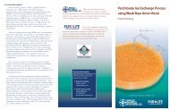
Polishing<br />
Degradation of sugars through bacterial action or excessive residence time on the fractionation<br />
resin at elevated temperatures can produce contaminants which decrease the long-term<br />
color stability of the finished product. Additionally, incomplete purification prior to chromatographic<br />
separation may have left unwanted impurities in the product stream. These<br />
impurities can be removed from the product prior to final evaporation using strong base<br />
anion resins in the salt form by themselves or in the hydroxide form with a companion bed<br />
of strong acid cation resin intermixed with the anion. The units utilizing the companion<br />
cation resins are termed mixed beds and remove color, ash, HMF and residual protein to<br />
produce a consistent quality of finished product.<br />
3
C ORN SWEETENER REFINING WITH ION EXC HANGE RESINS<br />
Resin Structure<br />
The vast majority of ion exchange resins utilized in corn sweetener refining are copolymers<br />
of styrene and divinylbenzene which have been activated with sulfuric acid or one of a number<br />
of amine compounds to produce cation and anion resins respectively:<br />
4<br />
Styrene and Divinylbenzene Copolymer Strong Acid<br />
Cation Resin<br />
CH<br />
CH 2<br />
CH CH CH<br />
2<br />
CH CH2 CH<br />
Weak Base<br />
Anion Resin<br />
CH CH2 CH CH2 SO 3 H CH 2 N(CH 3 ) 2<br />
The insoluble resin matrix and bonded functional groups are capable of exchanging<br />
ions or adsorbing molecules from solution and thereby affecting a change in the ionic or<br />
molecular concentrations of the syrup. These properties have made the use of ion exchange<br />
resins critical in HFCS refining.
Unit Operation Process Design<br />
Demineralization Process<br />
Glucose syrup from starch hydrolysis contains ash, color bodies and proteinaceous materials<br />
which produce an unacceptable color, taste or odor quality in the finished product and<br />
reduce isomerization enzyme performance. Whether the syrup will be evaporated and<br />
sold as a finished product or continue on in the refining process to isomerization,<br />
demineralization is required to remove objectionable soluble components. Color stability<br />
of some corn syrups is obtained through the addition of sulfur dioxide, but due to human<br />
sensitivity to sulfites, this practice has partly been replaced with ion exchange.<br />
The ash content of glucose syrups is typically 0.25-0.45% by weight of total syrup dry<br />
solids and predominantly contains the following ions:<br />
• Sodium Na +<br />
• Calcium Ca ++<br />
• Magnesium Mg ++<br />
• Chloride Cl -<br />
--<br />
• Sulfate SO4 5<br />
C ORN SWEETENER REFINING WITH ION EXC HANGE RESINS<br />
To facilitate isomerization of dextrose to a 42% fructose solution, salts are added back to<br />
the syrup after demineralization and will he present in the 42% fructose. These salts must<br />
be removed prior to final evaporation or chromatographic separation. The ash content of 42<br />
HFCS is typically 0.15-0.25% by weight of total syrup dry solids and consists primarily of:<br />
• Sodium Na +<br />
• Magnesium Mg ++<br />
--<br />
• Sulfate SO4 --<br />
• Sulfite SO3 As the dextrose or fructose syrup solution passes through the resin bed, the sugars, ash,<br />
color bodies and proteins diffuse into the resin beads and can be exchanged or adsorbed onto<br />
the resin. In the strong acid cation bed, sodium, calcium, magnesium and other cations will<br />
replace the hydrogen ions on the resin due to their greater affnity for the resin than hydrogen<br />
ion. The hydrogen ions displaced from the resin by other cations cause a drop in the<br />
solution pH to a level of about 1.5-2.0 in the “primary” cation column and 3.0-3.5 in the<br />
“secondary” cation column. Thus, neutral salts are changed to their corresponding mineral<br />
acids. Proteinaceous compounds, at low pH, may be sorbed onto the cation resin either by<br />
ion exchange or adsorption on the resin matrix.<br />
The syrup then passes through a bed of weak base anion resin where the mineral acids,<br />
organic acids and color bodies diffuse into the resin beads and are adsorbed onto the tertiary<br />
amine functional groups. The chemical equations depicting the service ion exchanges are<br />
shown below:<br />
Strong Acid Cation Service <strong>Exchange</strong> Reaction<br />
– + + – – + + –<br />
RSO3 H + Na Cl ➔ RSO3 Na + H Cl (Produces mineral acids)<br />
Weak Base Anion Service <strong>Exchange</strong> Reaction<br />
RCH2 N (CH3) 2 + H + Cl – ➔ RCH2NH + Cl – (CH3) 2 (Acid adsorber)<br />
(“R” indicates the resin matrix)
C ORN SWEETENER REFINING WITH ION EXC HANGE RESINS<br />
6<br />
The weak base anion resin has negligible mobile OH – counter ion which can be<br />
exchanged by an anion in solution. <strong>With</strong>out this ability to split neutral salts, the weak base<br />
anion resin must rely on the cation resin to first produce acids in order for it to remove ions<br />
by acid adsorption.<br />
The service breakthrough point can be more easily and accurately detected prior to leakage<br />
of impurities if it is consistently the result of anion resin exhaustion rather than cation<br />
resin exhaustion. Because of this, demineralization systems are typically operated with an<br />
excess amount of cation exchange capacity (not necessarily volume) relative to anion acid<br />
adsorption capacity. This ensures that the service breakthrough point is consistently the<br />
result of anion exhaustion. The designated exhaustion point corresponds to a rapid increase<br />
in mineral acid leakage from the anion resin, a pH drop, conductivity rise and/or an increase<br />
in color leakage. A typical service effluent profile is indicated in Figure A.<br />
While the affinity of the cation resin for highly dissociated salts is good, the affinity<br />
for proteinaceous materials is much weaker and the cation resin will leak higher percentages<br />
of proteins during service as shown on the cation leakage curve (Figure B). The weak<br />
organic acids show less affinity for the weak base anion resin than do the mineral acids and<br />
will also leak through in greater percentages as indicated in the anion leakage curve (Figure<br />
C). To prevent proteins and organic acids from affecting the finished product quality, the<br />
syrup is typically passed through a secondary cation/anion pair for more complete removal of<br />
the impurities leaking from the primary demineralizer pair. This two-pass demineralization<br />
system will remove 95-98% of the salts, 65-75% of the protein, 50-75% of the weak acids<br />
and 70-90% of the color.<br />
Upon reaching the service exhaustion point of the primary demineralizers, the primary<br />
pair is regenerated, the secondary pair is moved into primary demineralization service and a<br />
third pair of freshly regenerated demineralizers is placed into secondary demineralization<br />
service. This sequence is commonly referred to as “Merry Go Round” service. Alternative<br />
configurations include systems utilizing a multiport valve and a number of rotating resin<br />
beds and systems utilizing fixed upflow service dual compartment columns. Another equipment<br />
arrangement for glucose and fructose demineralization commonly used in the Pacific<br />
Rim is a demineralizer two-bed pair coupled with a polishing strong base anion (Type II)<br />
mixed bed for even greater removal of the soluble impurities at the expense of some chemical<br />
efficiency. The higher product quality can increase isomerase enzyme life and provide a<br />
better feed for the fructose enrichment system. In this scheme one cation/anion/mixed bed<br />
train is in service while a second is in regeneration.<br />
Upon exhaustion, the syrup is displaced from the resin bed and the resin is restored to<br />
a working condition with a chemical regeneration treatment. The metal ions are displaced<br />
from the cation resin by passage of a strong mineral acid in an amount in excess of the<br />
stoichiometric exchange capacity of the resin in order to drive the equilibrium reaction.<br />
Hydrochloric acid is widely preferred to regenerate cation resins by displacing the metal<br />
ions and stripping off the proteinaceous compounds. The acids adsorbed onto the weak base
7<br />
anion resin are neutralized utilizing a base such as sodium hydroxide, sodium carbonate<br />
or aqueous ammonia. This acid neutralization is accomplished with a smaller excess of<br />
regenerant chemical than is required for the cation resin. The chemical equations depicting<br />
the regeneration exchanges are shown below:<br />
Strong Acid Cation Regeneration <strong>Exchange</strong> Reaction<br />
– + + – – + + –<br />
RSO3 Na + H Cl ➔ RSO3 H + Na Cl (Equilibrium controlled)<br />
Weak Base Anion Regeneration <strong>Exchange</strong> Reaction<br />
RCH2 NH + Cl – (CH3) 2 + Na + OH – ➔ RCH2 N (CH3) 2 + Na + Cl – + H2O (Acid neutralization)<br />
(“R” indicates the resin matrix)<br />
C ORN SWEETENER REFINING WITH ION EXC HANGE RESINS<br />
Regeneration of the resins is accomplished in a simultaneous sequence as follows:<br />
1. Sweeten Off : Syrup is displaced from the cation/anion pair by introduction of condensate<br />
or demineralized water into the cation column which then pushes the syrup out<br />
through the anion. This step continues until the anion effluent syrup concentration has<br />
decreased to 0.1- 0.5 % dry solids (Figure D).<br />
2. Backwash: Process water is passed in an upflow direction simultaneously in both the<br />
cation and anion columns to fluidize the resin to allow particulates and resin fines to<br />
pass up through the beds and out of the vessels.<br />
3a. Chemical-In Cation: A dilute hydrochloric acid solution passes through the bed<br />
exchanging hydrogen ions for the metal cations fixed onto the resin. While sulfuric acid<br />
could alternately be used, a lower operating capacity is achieved and the threat of calcium<br />
sulfate precipitation makes it less desirable.<br />
3b. Chemical-In Anion: A dilute basic solution passes through the resin bed neutralizing<br />
and releasing the adsorbed acids. Sodium hydroxide, sodium carbonate or aqueous<br />
ammonia can be used as a weak base anion regenerant.<br />
4. Cleanup Regeneration: At intervals of once per 5 to 25 cycles it becomes desirable to<br />
strip off proteins adsorbed onto the cation resin utilizing caustic or ammonia. Organic<br />
acids adsorbed onto the anion resin are stripped utilizing an alkaline brine or hydrochloric<br />
acid solution. Following the cleanup regeneration is another chemical-in step with a<br />
double dosage of regenerant chemical.<br />
5. Slow Rinse: Water passes through the resins and pushes out the regenerant chemical<br />
at a rate which ensures sufficient contact time for completion of regeneration. The use<br />
of condensate or demineralized water ensures that no precipitation will occur and no<br />
dissolved ions in the slow rinse water will exchange onto the resin and decrease its<br />
exchange capacity for the subsequent service cycle.<br />
6. Fast Rinse: Condensate or demineralized water is used to rinse out the residual chemical<br />
in the beds.<br />
7. Series Rinse: Condensate or demineralized water passes through the cation and anion<br />
beds in series in a once-though or recirculating manner until the effluent quality reaches<br />
the desired conductivity limit of 10-30 microsiemens/cm (µS/cm).<br />
8. Sweeten On: Syrup is passed in series through the cation and anion beds displacing the<br />
rinse water. Sweeten On is terminated when the anion effluent dry solids concentration<br />
reaches in excess of 95% of the feed syrup solids concentration (Figure E).
C ORN SWEETENER REFINING WITH ION EXC HANGE RESINS<br />
The demineralization sequence chart below lists the various process modes and typical<br />
parameters.<br />
Demineralizer Sequence<br />
FLOW RATE VOLUME<br />
OPERATION SOLUTION [BED VOLS/HR] [BED VOLS]<br />
1. SWEETEN OFF H2O 2.0-4.0 1.5-3.0<br />
2a. BACKWASH CATION H2O 1.0 ft/min 1.5-2.0<br />
2b. BACKWASH ANION H2O 0.33 ft/min 1.0<br />
3a. CHEMICAL IN CATION 7% HCI 1.0-1.5 1.0<br />
3b. CHEMICAL IN ANION 4% NaOH 1.0-2.0 1.5<br />
4a. CLEANUP CATION 4% NaOH 1.0-2.0 1.0<br />
(Alternate) 3% NH3 1.0-1.5 1.5<br />
4b. CLEANUP ANION 7% HCl 1.0-1.5 1.0<br />
(Alternate) 1% NaOH/10% NaCI 1.0 1.5<br />
5a. SLOW RINSE CATION H2O 1.0-1.5 1.5<br />
5b. SLOW RINSE ANION H2O 1.0-2.0 1.5<br />
6a. FAST RINSE CATION H2O 10-20 2.0-4.0<br />
6b. FAST RINSE ANION H2O 10-20 3.0-5.0<br />
7. SERIES RINSE H2O 5-10 2.0-5.0<br />
8. SWEETEN ON 30-50% DS SYRUP 2.0-4.0 1.0<br />
9. SECONDARY SERVICE 30-50% DS SYRUP 2.0-4.0 30-60<br />
10. PRIMARY SERVICE 30-50% DS SYRUP 2.0-4.0 30-60<br />
Demineralization Equipment<br />
The demineralization equipment train typically consists of three cation/anion pairs or two<br />
cation/ anion/mixed bed triplexes. The equipment utilizes food grade rubber lined carbon<br />
steel pressure vessels containing two or three sets of distributors made of CPVC or stainless<br />
steel and wrapped with polypropylene or stainless steel screen. In anion columns which do<br />
not see a hydrochloric acid cleanup solution, stainless steel distributors are often employed<br />
for greater strength against the large shrink/swell and pressure drop forces in the bed.<br />
Piping manifolds utilize polypropylene-lined carbon steel, rubber lined carbon steel or stainless<br />
steel pipe. Control of fluid direction is accomplished utilizing lined and stainless steel<br />
plug valves, butterfly valves or diaphragm valves. Service flow can proceed either down<br />
through the resin beds, maintaining them packed in the lower half of the vessels, or up<br />
through the resins, maintaining them in a packed state in the upper half of the vessels.<br />
Compartmentalized vessels with external backwash are also utilized.<br />
The vessels are most commonly operated with a “water dome” (water fills the freeboard<br />
space between the middle and top distributors) rather than an “air dome” to improve rubber<br />
lining life and minimize microbiological activity in the vessels during service.<br />
Improved product quality can be obtained from the cation resin by utilizing regenerant<br />
chemical passed in a direction counter to the service flow. Since the syrup leaving the cation<br />
column is in equilibrium with the resin located at the outlet collector, the counter-flow passage<br />
of regenerant chemical creates an area of highly regenerated resin at the column effluent.<br />
At constant chemical dosage, the cation effluent quality is constant and contains less<br />
impurities than a co-flow regenerated cation resin bed.<br />
8
C ORN SWEETENER REFINING WITH ION EXC HANGE RESINS<br />
If the backwash step can be utilized only infrequently, then the resin bed will be<br />
undisturbed during regeneration and a counter-flow regeneration may produce a high<br />
quality syrup with the same throughput capacity at a somewhat lower chemical dosage.<br />
Since a weak base anion regeneration is an acid neutralization step and only a small excess of<br />
regenerant is required, no advantage is gained from counter-flow regeneration of the<br />
weak base resin.<br />
Separation Process<br />
In the production of 55 HFCS from dextrose, an economical limit of 42-46% fructose is<br />
achieved using isomerase enzyme. To obtain a higher purity fructose solution, the dextrose<br />
and fructose must be separated to produce two fractions, both of which are enriched in<br />
either sugar. This is accomplished via chromatographic separation on a fractionation ion<br />
exchange resin. The fructose-rich fraction can be blended into a 55% fructose solution while<br />
the dextrose-rich fraction is recycled in the HFCS refining process.<br />
Owing to a greater number of sites available for hydrogen bonding, the fructose molecule<br />
will form a coordination complex with calcium ions fixed onto a strong acid cation<br />
resin. This results in a preferential affinity of the resin for the fructose molecule over the<br />
glucose molecule and hence a chromatographic separation of the two sweeteners as they pass<br />
through the resin bed. From a feed solution containing a purity of 42% fructose by weight,<br />
the fructose in the product fraction can reach in excess of 99% purity. However, when producing<br />
55% fructose, the optimum productivity and efficiency of the system is achieved by<br />
enriching to an 85-90% fructose concentration and blending this product with a 42% fructose<br />
solution to produce the 55% fructose which matches the sweetness of sucrose in soft<br />
drinks. When enriching to produce crystalline fructose, a product purity in excess of 95%<br />
fructose is desired prior to the crystallization step.<br />
When enriching fructose to produce 55 HFCS with a simulated moving bed chromatographic<br />
separation system (see next section), a product purity of 90% fructose can be<br />
achieved at a 90% recovery of the fructose in the feed steam and a desorbent consumption of<br />
1.1-1.25 lbs. water per lb. of 55 HFCS dry solids. The production achieved will be approximately<br />
200 lbs. of 55 HFCS dry solids/cu. ft. resin per day depending on the type of system<br />
and resin utilized. At constant production and desorbent consumption the purity and recovery<br />
will vary inversely with each other.<br />
9<br />
Chemical Efficiency, [%]<br />
100<br />
80<br />
60<br />
40<br />
20<br />
Co-flow<br />
Chemical Usage<br />
[gm HCl/L]<br />
40 80 120 160 200<br />
Counter-flow<br />
2.5 5.0 7.5 10.0 12.5<br />
Chemical Usage<br />
[lb. HCl/cf]<br />
100<br />
80<br />
60<br />
40<br />
20<br />
Effluen Leakage, [PPM]<br />
40<br />
30<br />
20<br />
10<br />
0<br />
Cation<br />
Leakage<br />
Co-flow<br />
Counter-flow<br />
50 100<br />
Throughput<br />
[% of the Cycle]
C ORN SWEETENER REFINING WITH ION EXC HANGE RESINS<br />
10<br />
Chromatographic separation of dextrose is also commercially practiced to separate the<br />
dextrose from the oligosaccharides and produce a dextrose purity in excess of 99% in order<br />
to minimize unwanted byproducts in the subsequent hydrogenation to sorbitol or in fermentation.<br />
Dextrose separation from oligosaccharides occurs due to a difference in the rate<br />
of diffusion into and out of the monovalent form cation fractionation resin.<br />
Fructose Enrichment Material Balance<br />
W: 153.36<br />
G: 95.5<br />
O: 4.5<br />
DS: 100.0<br />
W: 150.0<br />
F: 57.71<br />
G: 73.36<br />
O: 6.26<br />
DS: 137.33<br />
W: 91.55<br />
F: 30.68<br />
F: 27.03<br />
Blend G: 38.93<br />
Feed<br />
G: 34.43 Water<br />
O: 3.36<br />
O: 2.90<br />
DS: 72.97<br />
DS: 64.36<br />
W: 115.0<br />
W: 48.65<br />
W: 42.91<br />
F: 24.32<br />
G: 1.57<br />
O: 1.14<br />
DS: 27.03<br />
W: 63.00<br />
F: 55.00<br />
G: 40.50<br />
O: 4.50<br />
DS: 100.00<br />
W: 111.65<br />
Product<br />
55 HFCS<br />
Starch Hydrolyzate<br />
Isomerization<br />
Evaporation<br />
42 HFCS<br />
Chromatographic<br />
Byproduct<br />
F: 2.71<br />
G: 32.86<br />
O: 1.76<br />
DS: 37.33<br />
W: 94.91<br />
Chromatographic separation is a diffusion controlled process and those variables that<br />
affect the length of diffusion path, uniformity of diffusion path and ease of diffusion through<br />
the resin bed will affect the performance of the separation. Separation performance is affected<br />
by resin characteristics such as bead size, bead uniformity, moisture, capacity and bead<br />
strength. For example, increasing moisture will improve diffusion through the resin,<br />
decreasing particle size will reduce the length of the diffusion path and increasing bead uniformity<br />
will equalize the diffusion path for all species at a given mass transfer stage. The<br />
combination of these resin characteristics is interrelated and optimization is dependent both<br />
on process performance requirements and the particular separation system design.<br />
F<br />
G<br />
O<br />
DS<br />
W<br />
= = Fructose<br />
= Glucose<br />
= Oligosaccharides<br />
= Dry Solids<br />
= Water
Enrichment Equipment<br />
Fructose and dextrose enrichment had initially been accomplished in batch separation systems<br />
where introduction of a pulsed volume of feed was both preceded and followed by<br />
recycle fractions and then eluted with desorbent water. In the 1970s, the technology was<br />
developed for continuous chromatographic separation of fructose utilizing a simulated moving<br />
bed (SMB) separation system. The SMB technology employs continuous feed and desorbent<br />
introduction and continuous product and byproduct withdrawal into and out of a<br />
recirculating fluid flow. The recirculating fluid flow can range up to six times greater than<br />
the feed flow rate.<br />
11<br />
Simulated moving bed chromatographic separation system<br />
DESORBENT<br />
PRODUCT<br />
FEED<br />
BYPRODUCT<br />
A<br />
D<br />
S<br />
O<br />
R<br />
B<br />
E<br />
N<br />
T<br />
In the SMB system, fructose purity in the resin bed upstream from the feed introduction<br />
point increases as the distance away from the feed point increases. From a feed inlet reference<br />
point, it seemingly appears that the adsorbent media is moving upstream and carrying<br />
with it the fructose molecules which it has adsorbed, thus the terminology “Simulated<br />
Moving Bed”.<br />
Fructose enrichment simulated moving bed<br />
DESORBENT<br />
PRODUCT<br />
[90 HFCS]<br />
FEED<br />
[42 HFCS]<br />
BYPRODUCT<br />
C ORN SWEETENER REFINING WITH ION EXC HANGE RESINS<br />
FRUCTOSE<br />
CONCENTRATION<br />
DEXTROSE<br />
CONCENTRATION
C ORN SWEETENER REFINING WITH ION EXC HANGE RESINS<br />
12<br />
D t<br />
P t<br />
F t<br />
B t<br />
The SMB separation system is divided into four process zones with each zone having<br />
a unique flow rate. A fifth zone is added when withdrawal of a polysaccharide rich stream<br />
is desired.<br />
DESORBENT<br />
PRODUCT<br />
FEED<br />
BYPRODUCT<br />
ZONE IV<br />
ZONE III<br />
ZONE II<br />
ZONE I<br />
ZONE IV<br />
Once a stable concentration profile has been established across the entire length of the<br />
separation system it moves slowly down the system with the aid of the recirculation flow.<br />
The sugar concentrations are maintained constant by moving the location of the feed,<br />
desorbent, product and byproduct inlet and outlet points down the system at the same<br />
rate as the concentration profile moves.<br />
TIME t<br />
Movement of the introduction and withdrawal points is accomplished using either a<br />
multiport valve or with multiple manifolds of two-position valves.<br />
Auxiliary systems complement the chromatographic separation system. Degasification<br />
of feed and desorbent streams prior to introduction to the resin bed ensures minimal<br />
oxidation of the resin will occur. Calcium salt addition to the separator feed is sometimes<br />
utilized to maintain a high calcium ion content on the resin, but this increases the ash<br />
load to the polishing mixed beds by a small amount.<br />
Dt D<br />
t+1<br />
Pt Pt+1 Ft Ft+1 Bt Bt+1 TIME t+1
Polishing Process<br />
The fractionation system product fraction contains 85-90% fructose and can also contain<br />
ppm quantities of impurities such as color bodies, weak acids, HMF, residual ash and protein.<br />
The level of impurities can vary as a result of the fractionation system operating conditions<br />
or performance of upstream refining unit operations. To produce a heat stable product<br />
of consistently high quality (See Table L for 55 HFCS specs), the syrup can be polished by<br />
passage through a single bed of strong base anion resin or a mixed bed of strong acid<br />
cation/strong base anion resin. The syrup can be treated as a 90% fructose solution or, after<br />
blending, as a 55% fructose solution.<br />
A salt form strong base anion resin will remove color bodies to produce a heat stable<br />
product. These strong base anion polishers can be operated with a single bed in service<br />
while the second bed of the pair is in regeneration or on standby. Salt regeneration with<br />
occasional caustic cleanup is sufficient to remove color. For complete removal of weak acids,<br />
HMF, ash and protein in addition to color, a mixed bed of hydrogen form strong acid cation<br />
resin and hydroxide form strong base anion resin (Type II) is utilized. In order to more<br />
closely match the capacity of the cation and anion resins, a 50% excess of strong base anion<br />
resin volume is required to approximately equalize the number of anion exchange groups<br />
with the number of cation exchange groups in the mixed bed column since the capacity per<br />
unit volume of the strong base anion resin may be 40-50% lower than the cation resin.<br />
Thus, the mixed bed resin volume will typically be 60% anion and 40% cation.<br />
Some degradation of the HFCS can occur in the mixed bed due to contact with the high<br />
pH strong base anion resin. Fructose will convert to psichose at elevated pH, so to limit the<br />
amount of fructose lost in the mixed beds the velocity of the syrup is kept high enough to<br />
minimize contact time with the anion without affecting the kinetics of the mixed bed<br />
exchange.<br />
In service, syrup passes down through one bed of homogeneously mixed cation and<br />
anion resin while the second column of the pair is in regeneration or on standby. The<br />
primary function of a polisher is color removal and service is terminated based on color<br />
leakage. The conductivity of the mixed bed effluent at breakthrough will be on the order of<br />
1-2 µS/cm. Upon exhaustion of a polisher, the service unit is sweetened off and regenerated<br />
while the standby unit is sweetened on and put into service.<br />
To regenerate an exhausted mixed bed unit, syrup is displaced from the resin bed with<br />
water, the intermixed resins are separated from each other due to density difference with<br />
a backwash and each is then chemically regenerated. The cation resin is stripped of protein<br />
and ash with a dilute hydrochloric acid solution while the strong base anion resin is stripped<br />
of color bodies, weak acids, ash and HMF with a dilute caustic solution.<br />
The regeneration is accomplished in a stepwise sequence as follows:<br />
13<br />
C ORN SWEETENER REFINING WITH ION EXC HANGE RESINS<br />
1. Sweeten Off: Syrup is displaced from the bed of intermixed cation/anion resin by<br />
introduction of demineralized water into the feed distributor which pushes the syrup<br />
down through the bed and out to sweetwater collection. This step is terminated when<br />
the effluent sweetener concentration has decreased to 0.1-0.5% dry solids.<br />
2. Blowdown: The water in the freeboard space between the feed distributor and<br />
backwash collector is displaced by pushing the water down through the bed with<br />
pressurized air until the liquid level has reached the feed distributor point. Evacuation<br />
of the freeboard space results in less back pressure and hence a more rapid rise of the<br />
bed of mixed resin during the initial minutes of the backwash step. This provides for<br />
a better separation of the more dense cation resin from the lighter anion resin.
C ORN SWEETENER REFINING WITH ION EXC HANGE RESINS<br />
14<br />
3. Backwash/Separation: Process water is passed upflow through the bed of mixed resins<br />
to achieve a 100% fluidized expansion of the resin bed and accomplish a separation of<br />
the cation from the anion resin in addition to removing resin fines and particulates from<br />
the bed. Owing to specific gravity differences, the anion resin will be fluidized to a<br />
greater height in the vessel and settle at a slower velocity than the heavier cation resin.<br />
Thus, the cation and anion resin separate into two discrete beds with the resin interface<br />
occurring at the same level in the vessel as the interface takeoff distributor.<br />
4. Chemical-In Anion: The dilute caustic solution continues to enter the feed distributor<br />
located above the separated resin bed and passes down through the anion bed and out<br />
the interface collector while a simultaneous flow of deionized water enters the bottom<br />
distributor and passes up through the cation resin and out through the interface<br />
collector with the spent caustic solution. The 50% excess volume of strong base anion<br />
resin requires a regenerant chemical volume in excess of the cation regenerant volume.<br />
In order to ensure equal contact times per unit volume of resin, regeneration of the<br />
anion resin begins prior to the cation resin.<br />
5. Chemical-In Cation/Anion: The dilute caustic solution continues to enter the feed<br />
distributor located above the separated resin bed and passes down through the strong<br />
base anion resin and out the interface collector while a simultaneous flow of dilute<br />
hydrochloric acid enters the bottom distributor and passes up through the cation bed<br />
and out the interface collector with the spent caustic solution.<br />
6. Slow Rinse Cation/Anion: Demineralized water streams simultaneously enter the feed<br />
and bottom distributors and pass down through the anion and up through the cation<br />
respectively and mix as they exit the column through the interface collector. The<br />
demineralized water displaces the regenerant chemicals from the resins at a rate which<br />
ensures that all of the resin receives an adequate regeneration contact time.<br />
7. Fast Rinse Cation/Anion: Demineralized water streams simultaneously enter the feed<br />
and bottom distributors and pass down through the anion bed and up through the<br />
cation bed respectively and out the interface collector to rinse out the residual chemicals<br />
from the bed. Due to the excess volume of strong base anion resin, and its higher rinse<br />
requirement per cubic foot, it is desirable to rinse the anion resin at a higher rate than<br />
the cation resin.<br />
8. Blowdown: Pressurized air enters the top head of the vessel and pushes the water in<br />
the freeboard space down through the resin until the liquid level reaches the feed<br />
distributor point. Lowering the liquid level prevents water and resin from being carried<br />
out the vent nozzle during the subsequent resin mixing steps.<br />
9. Air/Water Mix: An air/water mixture enters the bottom distributor and flows up<br />
through the bed producing a churning action which mixes the resin. The air escapes<br />
through a vent while the added water raises the liquid level in the column slowly.<br />
The water provides a strong initial hydraulic force to slightly fluidize the resin so the<br />
churning air bubbles will easily effect a mixing of the cation and anion resins.<br />
10. Air Mix: After the churning action is initiated with the air/water combination, the<br />
water flow rate is terminated and the resins continue mixing through the action of the<br />
air bubbling up from the bottom distributor and escaping out through the vent.<br />
11. Air Draindown: In order to settle the well-mixed resins without incurring a separation<br />
due to differences in terminal settling velocity, air continues to be introduced into the<br />
bottom or interface distributor with the vent valve closed while water is withdrawn<br />
from either the bottom or interface distributor.<br />
12. Fill: Demineralized water enters the top distributor to completely fill the mixed<br />
bed vessel with water.
13. Service Rinse: Demineralized water enters the top distributor and passes down<br />
through the freeboard space and through the resin until the effluent conductivity<br />
decreases to less than 1 microsiemen/cm. The speed at which the conductivity declines<br />
and the value attained serves as a check against the quality of the regeneration.<br />
14. Sweeten On: Syrup enters the feed distributor under a demineralized water dome and<br />
passes down through the intermixed resin bed and out the bottom collector until the<br />
effluent dry solids concentration equals 95% of the feed solids concentration.<br />
The following mixed bed polisher sequence chart lists the various process modes and<br />
typical parameters:<br />
HFCS Mixed Bed Polisher Sequence<br />
C ORN SWEETENER REFINING WITH ION EXC HANGE RESINS<br />
FLOW RATE VOLUME<br />
OPERATION SOLUTION [BED VOLS/HR] [BED VOLS]<br />
1. SWEETEN OFF H2O 2.0-4.0 1.5-3.0<br />
2. BLOWDOWN AIR 4.0 1.0<br />
3. BACKWASH H2O 0.9 ft/min 2.0<br />
4. CHEMICAL-IN ANION 4% NaOH 2.0 1.0<br />
H2O 2.0 1.0<br />
5. CHEMICAL-IN CATION 7% HCI 2.0 1.33<br />
ANION 4% NaOH 2.0 1.33<br />
6. SLOW RINSE CATION H2O 2.0 2.0<br />
ANION H2O 2.0 2.0<br />
7. FAST RINSE CATION H2O 5.0 5.0<br />
ANION H2O 5.0 5.0<br />
8. BLOWDOWN AIR 4.0 1.0<br />
9. AIR/WATER MIX AIR 5-6 scfm/sq ft 10 min<br />
H2O 0.24 ft/min<br />
10. AIR MIX AIR 5.5 scfm/sq ft 10 min<br />
11. AIR DRAIN DOWN AIR 5.5 scfm/sq ft 1-5 min<br />
12. FILL H2O 2.0-4.0 1.0<br />
13. SERVICE RINSE H2O 2.0-4.0 0.5-1.0<br />
14. SWEETEN ON 30-55% DS SYRUP 2.0-4.0 1.0<br />
15. SERVICE 30-55% DS SYRUP 2.0-4.0 35-100<br />
Mixed Bed Polisher Equipment<br />
The mixed bed polishing equipment typically consists of a pair of food grade rubber lined<br />
pressure vessels containing four sets of distributors. The distributors are constructed of<br />
stainless steel and CPVC piping wrapped with polypropylene screen and clamped to rubber<br />
lined steel support bars. The vessels contain a flat false bottom for resin support and sight<br />
windows in the sidewall for visual inspection of backwash expansion, separation and mixing<br />
of resins during regeneration.<br />
The piping manifolds utilize polypropylene lined carbon steel, rubber lined carbon<br />
steel or stainless steel pipe. Control of fluid direction is accomplished with lined and<br />
stainless steel plug valves, diaphragm valves or butterfly valves.<br />
15
C ORN SWEETENER REFINING WITH ION EXC HANGE RESINS<br />
<strong>Ion</strong> <strong>Exchange</strong> <strong>Resins</strong><br />
Resin Specifications<br />
Process performance and operating life of resins for any application are optimized through<br />
specification of the resin characteristics which affect them. They cannot, however, be independently<br />
optimized. Resin characteristics having a positive effect on operating capacity can<br />
have a negative effect on the useful life of the resin. Additionally, a set of characteristics<br />
optimized for one particular syrup refining application may not perform effectively for<br />
purification of another type of syrup solution. Optimization of resin characteristics for each<br />
type of application is achieved through specification of resin manufacturing variables.<br />
These variables include total capacity, salt splitting capacity, moisture, macroporosity,<br />
microporosity, average particle size, particle size uniformity and others. These characteristics<br />
affect the resin performance in the following ways:<br />
16<br />
1. Total capacity is a general indicator of operating capacity, but the two are not directly<br />
proportional. For a new resin in a syrup demineralization application, the operating<br />
capacity is typically 50-60% of the total theoretical capacity. The resins are limited by<br />
equilibrium and kinetic constraints from achieving their total theoretical capacity in<br />
typical syrup refining operations.<br />
2. Salt splitting, or strong base, capacity affects the physical stability of weak base anion<br />
resins by limiting the amount of reversible swelling which occurs upon exhaustion and<br />
also affects the resin’s moisture level.<br />
3. Moisture levels inside the resin beads affect the rate of diffusion of soluble ions and<br />
molecules into the resin bead where exchange or adsorption can occur. A higher<br />
moisture content in a resin improves the rate of diffusion.<br />
4. Macroporosity also facilitates diffusion into and out of the interior of the resin bead.<br />
Large organic molecules have greater difficulty diffusing out of gel resins, thus resulting<br />
in a higher degree of fouling of these resins. Additionally, macroporosity imparts<br />
flexibility to the resin bead which gives it greater physical durability when subjected<br />
to osmotic shock or mechanical stresses. Gel resins, not having macroporosity, are more<br />
susceptible to osmotic shock and mechanical attrition.<br />
5. The microporosity of the structure is determined by the degree of crosslinking and<br />
affects both ionic and molecular selectivity due to steric hindrance and water adsorption.<br />
6. Particle size affects the kinetics of ion exchange. Smaller resin beads have shorter film<br />
diffusion and particle diffusion path lengths for ions and molecules to travel.<br />
7. Uniformity of particle size affects both pressure drop through the bed and sharpness<br />
of the adsorption and desorption wavefronts. As the particle size distribution widens,<br />
the adsorption and desorption bandwidths also increase.
<strong>Corn</strong> <strong>Sweetener</strong> <strong>Refining</strong> <strong>Resins</strong><br />
Demineralization<br />
PUROLITE TOTAL STRONG MAX SIZE<br />
RESIN TYPE FEATURE CAPACITY MOISTURE BASE SWELL TEMP RANGE<br />
A-103S WBA, Macro Standard 1.6 Eq/L 48-55% 10-15% 20% 140°F 300-1200 µ<br />
PFA-103S WBA, Macro Uniform Size 1.6 Eq/L 48-55% 10-15% 20% 140°F 400-700 µ<br />
A-133S WBA, Macro High Capacity 1.9 Eq/L 43-49% 10-15% 20% 140°F 300-1200 µ<br />
A-148S WBA, Macro No Strong Base 1.6 Eq/L 40-45%
C ORN SWEETENER REFINING WITH ION EXC HANGE RESINS<br />
Higher Performance Weak Base Anion Resin<br />
<strong>Purolite</strong> A-133S has been developed to provide 20-25% more throughput per cycle<br />
than current commercial weak base anion resins using the same regeneration procedure,<br />
resulting in savings which EXCEED the cost of the resin itself. (See Figure L)<br />
<strong>Purolite</strong> A-133S gives superior performance in glucose, dextrose, fructose, polyols,<br />
maltodextrin and other hydrolyzate syrups.<br />
Impact on Regeneration Costs<br />
A throughput increase of 20-25% per service cycle equates to 20-25% less frequent<br />
regeneration with consequential savings in chemicals, sweetwater evaporation, water and<br />
waste costs.<br />
DOSE SAVINGS @ 20% SAVINGS @350 CYCLES<br />
NaOH 4.0 lbs/cf 0.80 lbs/cf 280 lbs/cf<br />
Sweetwater Evaporation* 15 gals/cf 3.0 gals/cf 1050 gals/cf<br />
Water & Wastewater** 70 gals/cf 14.0 gals/cf 4900 gals/cf<br />
*Includes sweeten on and sweeten off dilution<br />
**Includes backwash, chemical dilution, slow rinse and fast rinse water<br />
Additional advantages of <strong>Purolite</strong> A-133S that may be realized depending on operating<br />
plant requirements are:<br />
• Higher production rate with the same cycle time as current commercial resins.<br />
• Increased cycle life from a greater number of cycles before fouling reduces the throughput<br />
per cycle to the minimum level.<br />
• Large bead size providing minimal pressure drop and higher flow rates.<br />
• Excellent color removal.<br />
• Superior osmotic shock resistance reducing attrition losses.<br />
Life Expectancy<br />
The useful operating life of resin is limited by the physical and chemical degradation and<br />
fouling which occurs as a result of the particular operating conditions it is subjected to.<br />
These include service and regeneration temperatures, syrup dry solids concentration, organic<br />
load, cleanup regeneration frequency, type of regenerant chemical and selection of the<br />
criteria for the point of replacement. The table below lists the typical life cycle range for<br />
ion exchange resins in sweetener refining:<br />
18<br />
Resin Life Expectancy<br />
RESIN TYPE TYPICAL LIFE [No. of Cycles]<br />
A-103S, A-123S, A-133S WBA 350-750<br />
C-150S SAC-MACRO 1000-2000<br />
A-510S SBA-TYPE II 200-500<br />
PCR 642 Ca FRACTIONATION 5-10 years
Degradation<br />
Successful ion exchange refining of corn sweeteners will result in degradation of the resins in<br />
a number of ways. The predominant mechanism of degradation will differ depending on the<br />
type of resin, type of service and choice of regenerant chemical. The table below lists the<br />
predominant mechanisms of degradation for each type of resin product:<br />
19<br />
Degradation Mechanisms<br />
RESIN MECHANISM CAUSE<br />
C ORN SWEETENER REFINING WITH ION EXC HANGE RESINS<br />
Cation Fouling Irreversible Protein Adsorption<br />
Oxidation Dissolved Oxygen in Feed<br />
WB Anion Fouling Irreversible Organic Acid Adsorption<br />
Cation Oxidation Products<br />
Thermal High Operating Temperature<br />
Rapid Temperature Change<br />
High Rinse Temperature<br />
Osmotic Shock Rapid Change of Electrolyte Concentration<br />
Rapid <strong>Exchange</strong> of <strong>Ion</strong>s<br />
Mechanical Attrition Resin Abrasion<br />
High Pressure Drop Across Bed<br />
Physical Loss Backwash Overfluidization<br />
Leaking Distributor Screens<br />
SB Anion-Type II Thermal High Operating Temperature High<br />
Regeneration Temperature Irreversible<br />
Fouling Organic Acid Adsorption<br />
Fractionation Oxidation Dissolved Oxygen in Feed or Desorbent<br />
Mechanical Attrition Osmotic Shock Resin Abrasion<br />
Rapid Change in Syrup Solids Concentration<br />
Breakup Re-wetting dried resin with water only<br />
Rapid thawing of frozen resin<br />
In addition to the chemical mechanisms of degradation, the resin is also subject to<br />
breakdown through mechanical attrition and operational problems such as resin retaining<br />
screen failures and overfluidization during backwash.<br />
When a resin is in static equilibrium, the chemical bonding forces holding the copolymer<br />
network together are balanced by the osmotic swelling pressure from hydration of the functional<br />
groups which are attached to the polymer network. A rapid change in the ionic or<br />
syrup concentration of the solution will cause an osmotic pressure that is greater either<br />
inside or outside of the bead which cannot be relieved through solvation. This will result in<br />
stresses on the polymer backbone that can fracture and break resin beads. A rapid exchange<br />
on the resin of one type of ion with another ion of greatly differently hydrated radius will<br />
cause the resin to rapidly shrink or swell. These osmotic shock forces occur during each ion<br />
exchange or fractionation cycle during sweetening on, sweetening off and regeneration.
C ORN SWEETENER REFINING WITH ION EXC HANGE RESINS<br />
20<br />
Fouling of resins can occur as a result of irreversible adsorption of organic molecules or<br />
precipitation of salts within the resin matrix. When large molecular weight organic compounds<br />
become sorbed in the resin bead they can block the pores from further diffusion of<br />
ions or bind to an exchange site and prevent utilization of resin capacity. Organic acids with<br />
carboxylic groups can become irreversibly sorbed onto the resin due either to a high affinity<br />
or to a stereo-chemical effect. The carboxylic group will pick up sodium ions from a caustic<br />
regenerant solution which will hydrolyze only very slowly off the resin during the fast rinse.<br />
This “caustic cling” can result in an extended rinse requirement that is several times higher<br />
than new resin rinse requirements. The increase in rinse requirement becomes a measure of<br />
the degree of fouling. Precipitation of magnesium hydroxide can occur within a cation or<br />
anion resin bead causing high ion leakage and low capacity. The magnesium hydroxide will<br />
precipitate in a cation resin undergoing a cleanup regeneration with caustic if it is not first<br />
acid stripped. Magnesium hydroxide precipitation can occur in an anion resin if the rinse<br />
water is not at least softened or if the cation resin is overrun during service.<br />
CH 3<br />
CH<br />
CH 2<br />
N +<br />
CH 2<br />
CH 2<br />
OH<br />
-OH<br />
CH 2<br />
CH 3<br />
CH 3<br />
CH<br />
CH 2<br />
N<br />
CH 3<br />
CH 2<br />
WEAKEST BOND<br />
Hofmann degradation of strong-base resins. (Type II Strong Base Anion)<br />
When the temperature of the resin during service or regeneration becomes excessive, the<br />
rates of the degradation reactions which result in loss of functional groups increase to a significant<br />
level. The recommended maximum operating temperatures to minimize degradation<br />
of the sweetener refining resins are listed in the resin specifications table on page 17.<br />
Product degradation, rather than resin degradation, will limit the cation resin operating<br />
temperature, but the strong base anion resin will start to degrade significantly before the<br />
syrup. The Type II strong base anion resin in the polishing mixed beds is the least thermally<br />
stable resin. The most thermally susceptible bond on a Type II strong base anion resin is the<br />
bond holding the alcohol group to the nitrogen atom.<br />
CH 2<br />
OH<br />
CH<br />
H 2 O
If the bond undergoes cleavage, called a Hofmann degradation reaction, the particular<br />
functional group of the Type II strong base anion which has lost its alcohol group will<br />
become a tertiary amine with weak base exchange properties. Thus, the functional group<br />
will no longer split neutral salts and will adsorb colored compounds to a lesser degree. The<br />
other degradation product is vinyl alcohol which rearranges to acetaldehyde.<br />
Troubleshooting<br />
While most operational problems with ion exchange systems are the result of mechanical<br />
failure or improper conditions of the ion exchange equipment and support systems, there are<br />
also a number of process problems which can arise that can be more difficult to diagnose<br />
and correct. Listed below is a table of some common ion exchange process related problems:<br />
21<br />
Diagnosing <strong>Ion</strong> <strong>Exchange</strong> Problems<br />
CONDITIONS CAUSES<br />
C ORN SWEETENER REFINING WITH ION EXC HANGE RESINS<br />
1. Low Throughput Increase in the feed ash, color or dry solids concentration.<br />
Poor fluid distribution or collection.<br />
Incomplete regeneration.<br />
Low resin volumes.<br />
Fouled resins.<br />
Inaccurate volume totalization.<br />
Microbiological growth in resin bed.<br />
2. High Pressure Drop Resin fines not being backwashed out.<br />
Plugged distributors or strainers.<br />
Foreign particulates such as carbon, diatomaceous earth or<br />
microbiological growth plugging bed or laterals.<br />
High syrup viscosity due to a drop in temperature or increase in<br />
dry solids concentration.<br />
3. Excessive Rinse Organic fouling.<br />
High rinse or service temperature has caused thermal degradation.<br />
Poor fluid distribution or collection.<br />
4. Resin Breakup Poor rinse water quality.<br />
Excessive service pressure drop across resin bed.<br />
Osmotic shock from rapid volume change or electrolyte<br />
concentration change.<br />
5. High Conductivity or pH in Service Incomplete regeneration.<br />
Bleed through from leaking service or chemical valve.<br />
Poor fluid distribution or collection.<br />
Resin fouled or degraded.<br />
Excessive service flow rate.<br />
Cross mixing of cation and anion resins.
C ORN SWEETENER REFINING WITH ION EXC HANGE RESINS<br />
Macronet Adsorbent <strong>Resins</strong><br />
Starch hydrolyzate plants around the world are utilizing high surface area synthetic adsorbents<br />
to replace granular and powdered activated carbon for removal of color, taste, odor,<br />
HMF and other impurities from sweetener solutions. The Macronet line of chemically<br />
regenerated styrenic adsorbents offers economic, aesthetic and ease of process advantages for<br />
replacing carbon in the production of bottler’s quality syrup.<br />
Organic impurities are attracted and held to adsorbents by surface energies such as Van<br />
der Waals forces. Since adsorption is a surface phenomenon, the Macronet adsorbents are<br />
manufactured with large surface area in the range of 800-1100 square meters/gram. But<br />
molecules are three dimensional and not flat, so it is important for the surface area to conform<br />
to the molecular size of the impurities being adsorbed in order for the collective surface<br />
energy to be large enough to retain them. Thus, the surface area must be employed in<br />
micropores which are small enough to form an “adsorption cavity”. Most of the surface area<br />
of Macronet adsorbents are contained in adsorption cavities of less then 20 Angstroms diameter.<br />
Macronet also contains a significant population of large transport pores which facilitate<br />
rapid diffusion from the bulk fluid into the microporous region where adsorption occurs.<br />
The hydrophobic styrene/divinylbenzene matrix of the Macronet will readily adsorb<br />
nonpolar hydrophobic impurities. Since many of the impurities are polar or even ionizable<br />
molecules, the presence of hydrophilic ion exchange functional groups on the matrix<br />
improves the range of impurities which can be removed by attracting more hydrophilic<br />
compounds. The hydrophilic functional groups also improve the ease of regeneration of the<br />
adsorbent.<br />
22<br />
Macronet Operating Options<br />
A. Color Adsorber for Macronet MN-150 replaces conventional carbon powdered treatment of<br />
Non-demineralized Syrups glucose syrups.<br />
Expensive and dirty powdered carbon and carbon filters are replaced<br />
with a simple chemically regenerated unit operation which produces<br />
no solid discharge to handle.<br />
B. Taste and Odor Polishing The primary and secondary ion exchange pairs remove the vast majority<br />
of impurities, leaving the Macronet MN-500 available to remove the<br />
difficult taste and odor impurities and polish the color even further.<br />
C. Color, Taste and Odor A layered bed of MN-150 over MN-500 offers improved color and<br />
Polishing heat color removal in addition to taste and odor polishing.<br />
D. Color, Taste and Odor The layered bed of MN-150 over MN-500 is air mixed prior<br />
Polishing with Enhanced<br />
pH and Conductivity Stability<br />
to service to offer mixed bed quality pH and conductivity.<br />
E. Color, Taste and Odor A layered bed of MN-150 over a weak acid cation resin is air mixed prior<br />
Polishing with Enhanced<br />
pH Stability<br />
to service to offer better pH stability.
23<br />
Service and Regeneration Sequence <strong>Purolite</strong> MN-150<br />
TEMP FLOW VOLUME TIME<br />
STEP SOLUTION °C BV/hr BV MIN COMMENTS<br />
Service Syrup 40-60 2-5 30-200<br />
C ORN SWEETENER REFINING WITH ION EXC HANGE RESINS<br />
Sweeten off DI H 2O 40-60 4 2 30 Downflow<br />
1<br />
Backwash DI H2O 30-60 2.5 gpm 1.5-2.0 30 Upflow 50%<br />
sq ft Expansion<br />
2 NaOH In 1N NaOH 40-60 1 1.5 90 Downflow<br />
Slow Rinse DI H 2O 40-60 2 2 60 Downflow<br />
3,4 HCI In O.1N HCI 40-60 2 3 90 Upflow<br />
Slow Rinse DI H 2O 40-60 2 2 60 Upflow<br />
5 Fast Rinse DI H2O 40-60 4 4 60 Downflow<br />
1. For MN-500, the backwash flow rate should be increased to 6.0 gpm/sq ft.<br />
2. For HMF removal, the temperature should be increased to 110°C and the first 1 BV is allowed<br />
to soak for 2 hours.<br />
3. For MN-500 regeneration, the HCl concentration should be increased to 0.3 N.<br />
4. For a 1/3 MN-150 and 2/3 MN-500 layered bed, the HCl concentration should be increased<br />
to 0.2 N.<br />
5. For mixed bed operation, an air mix follows the Fast Rinse.
C ORN SWEETENER REFINING WITH ION EXC HANGE RESINS<br />
PUROLITE: About Us<br />
<strong>Purolite</strong>’s primary focus is resins for <strong>Ion</strong> <strong>Exchange</strong>; Catalysis &<br />
Specialty Applications.<br />
<strong>Purolite</strong> Corporation is a privately owned company, established in 1981. Since that time,<br />
<strong>Purolite</strong> has grown to become a leading supplier of specialty resins for the ion exchange, catalyst<br />
and specialty applications markets world-wide.<br />
<strong>Purolite</strong> has global manufacturing with factories in Philadelphia, USA, Victoria,<br />
Romania, and Hangzhou, China coupled with an established network of sales offices,<br />
distributors and agents located close to our customers. <strong>Purolite</strong> continues to develop its<br />
manufacturing capacity, product quality and innovation through investment in new<br />
equipment and improved research facilities.<br />
<strong>Purolite</strong> has the largest commitment to R&D of any specialty resin producer globally,<br />
and we strive to develop products that will give our customers a competitive edge. Our<br />
ability to quickly custom configure a solution that fits each customer's requirements is what<br />
sets <strong>Purolite</strong> apart from the competition.<br />
Our research and development is aimed at perfecting existing products, discovering new<br />
products for existing applications and finding new applications for our core technologies.<br />
Collaboration with our customers on specific needs is key is our success.<br />
<strong>Purolite</strong> is committed to developing products that have the minimum possible<br />
environmental impact.<br />
<strong>With</strong> our market-leading manufacturing capacity, broad product range and record of<br />
innovative research, <strong>Purolite</strong> has a unique commitment to the specialty resins marketplace.<br />
<strong>Purolite</strong> manufactures products which are widely used in; pharmaceutical production;<br />
electronics (where our low TOC resins meet the demand for Ultra Pure water for manufacturing<br />
semiconductors); chemical and refining industries; trans-esterification and catalysis:<br />
the food industry: metals extraction and chelation; electroplating; nuclear power generation;<br />
sugar and sweetener refining.<br />
Special Applications<br />
For some time, the sugar, sweetener and food industries have been using ion exchange resins<br />
for different types of decalcification, decolorization, demineralization, taste and odor<br />
removal, chromatography and ion exclusion. Products such as PUROLITE C-100S, C-155S,<br />
C-150S, A-500PS, A-510S, A-103S, A-860S, MN-150, MN-500, and PUROLITE<br />
Chromatographic <strong>Resins</strong> (PCR’s) have been widely used for these applications. Dairy<br />
processes, fruit juices and wine products also benefit from this unique treatment by ion<br />
exchange. PUROLITE’s manufacturing plant in Philadelphia is a world leader in the field of<br />
chromatography. Their product line of PCRs are utilized worldwide to purify and separate<br />
dextrose, fructose, beet molasses, polyols and other sweeteners. PCR products are tailormade<br />
to exacting specifications, meeting the demands of these industries.<br />
24
25<br />
C ORN SWEETENER REFINING WITH ION EXC HANGE RESINS<br />
The quality of PUROLITE ion exchange resin conforms with the stringent purity<br />
requirements of the pharmaceutical industry, which frequently uses resins and absorbents in<br />
its processes (extraction, separation, purification and concentration), and also in galenic<br />
pharmacy (drug carriers). The resins used (in bead, granular or powder form) have either<br />
strong or weak functional groups or have absorbent properties.<br />
Enzyme fixation currently involves specific ion exchange resins. PUROLITE resins<br />
now play a major role in all these specialty fields. PUROLITE works along with<br />
pharmaceutical companies in both research and production to optimize products for<br />
their specific applications.<br />
The chemical industry also uses ion exchange resins in many applications such as<br />
aldehyde and alcohol purification, separation and extraction of various chemicals.<br />
Focusing its resources on ion exchange alone, PUROLITE is uniquely equipped to solve<br />
its customers’ most complicated problems. This commitment, along with a dedication to<br />
excellence, has brought PUROLITE to a position of world leadership in ion exchange.
C ORN SWEETENER REFINING WITH ION EXC HANGE RESINS<br />
Sophisticated analytical equipment and<br />
techniques are employed during manufacture<br />
to ensure optimum performance or the resin.<br />
In addition, this equipment is used to troubleshoot<br />
issues and analyze resin performance to<br />
developed optimum customer solutions.<br />
ICP Spectrophotometer<br />
26<br />
Bench Scale Studies<br />
ICP and AA Spectrophotometers
A key tool in investigating the health<br />
of a resin is the microscope. Customers<br />
resins are routinely sent to <strong>Purolite</strong><br />
Laboratories for evaluation of performance<br />
and expectected use life.<br />
Gel <strong>Ion</strong> <strong>Exchange</strong> Resin<br />
27<br />
C ORN SWEETENER REFINING WITH ION EXC HANGE RESINS<br />
Macroporous <strong>Ion</strong> <strong>Exchange</strong> Resin<br />
Microscope Resin Evaluation
Packaging Options<br />
C ORN SWEETENER REFINING WITH ION EXC HANGE RESINS<br />
28<br />
Packaging Plant<br />
Bulk Tanker Truck Resin Delivery<br />
<strong>Purolite</strong> offers a range of packaging options from<br />
bulk tanker delivery through super sacks, fiber<br />
drums and small boxes and bags to suit individual<br />
customer requirements.
Ce/Cf<br />
Ce/Cf<br />
Figure A: Typical Service Cycle<br />
12<br />
10<br />
8<br />
6<br />
4<br />
2<br />
0<br />
10 20 30 40 50 60 70<br />
Throughput (Bed Volumes)<br />
Figure C: Anion Leakage<br />
1.5<br />
1.2<br />
0.9<br />
0.6<br />
0.3<br />
0<br />
■ Weak Acids<br />
■ Mineral Acids<br />
29<br />
■ pH<br />
■ Heat Color<br />
■ Color<br />
■ Conductivity<br />
10 20 30 40 50 60 70<br />
Throughput (Bed Volumes)<br />
C ORN SWEETENER REFINING WITH ION EXC HANGE RESINS<br />
Ce/Cf<br />
Figure B: Cation Leakage<br />
1.5<br />
1.2<br />
0.9<br />
0.6<br />
0.3<br />
0<br />
■ Proteins<br />
■ Ash<br />
10 20 30 40 50 60 70<br />
Throughput (Bed Volumes)<br />
Ce= Concentration in effluent<br />
Cf= Concentration in feed
Ce/Cf<br />
Capacity (Eq/L CaCO 3)<br />
Figure D: Sweeten-off<br />
1.0<br />
0.8<br />
0.6<br />
0.4<br />
0.2<br />
0<br />
C ORN SWEETENER REFINING WITH ION EXC HANGE RESINS<br />
0.5 1.0 1.5 2.0 2.5 3.0 3.5<br />
Throughput (Bed Volumes)<br />
Figure F: Cation Operating Capacity<br />
1.2<br />
1.0<br />
0.8<br />
0.6<br />
0.4<br />
0.2<br />
0<br />
2 4 6 8 10<br />
Regeneration Levels (lbs. HCI/ft3)<br />
30<br />
Ce/Cf<br />
Conductivity (Microsiemens/cm)<br />
Figure E: Sweeten-on<br />
1.0<br />
0.8<br />
0.6<br />
0.4<br />
0.2<br />
0<br />
0.2 0.4 0.6 0.8 1.0 1.2 1.4<br />
Throughput (Bed Volumes)<br />
Figure G: Conductance vs. NaCI Concentration<br />
in Syrup and Water<br />
600<br />
500<br />
400<br />
300<br />
200<br />
100<br />
0<br />
■ 40% DS Syrup @ 110 Deg F<br />
■ Deionized H20 @ 110 deg F<br />
100 200 300 400 500 600<br />
NaCI Concentration (ppm)
Bed Expansion %<br />
Pressure drop (psi/ft bed depth)<br />
Figure H: C-150S Backwash Expansion<br />
140<br />
120<br />
100<br />
80<br />
60<br />
40<br />
20<br />
0<br />
■ 110 deg F<br />
■ 95 deg F<br />
■ 77 deg F<br />
■ 60 deg F<br />
1 2 3 4 5 6 7 8 9 10 11 12 13<br />
Backwash Flowrate (gpm/sq ft)<br />
Figure J: C-150S Pressure Drop in Syrup<br />
2.5<br />
2.0<br />
1.5<br />
1.0<br />
0.5<br />
0<br />
■ 57% DS<br />
■ 52% DS<br />
■ 35% DS<br />
31<br />
1 2 3<br />
Flow rate (gpm/sq ft)<br />
C ORN SWEETENER REFINING WITH ION EXC HANGE RESINS<br />
Bed Expansion %<br />
Pressure drop (psi/ft bed depth)<br />
Figure I: A-103S Backwash Expansion<br />
100<br />
80<br />
60<br />
40<br />
20<br />
0<br />
■ 40 deg F<br />
■ 50 deg F<br />
■ 60 deg F<br />
■ 70 deg F<br />
■ 80 deg F<br />
■ 110 deg F<br />
1 2 3 4 5<br />
Backwash Flowrate (gpm/sq ft)<br />
Figure K: A-103S Pressure Drop in Syrup<br />
3.0<br />
2.5<br />
2.0<br />
1.5<br />
1.0<br />
0.5<br />
0<br />
■ 57% DS<br />
■ 52% DS<br />
■ 35% DS<br />
1 2 3<br />
Flow rate (gpm/sq ft)
lbs of Syrup DS/ft3 Resin<br />
C ORN SWEETENER REFINING WITH ION EXC HANGE RESINS<br />
Figure L: High Capacity Weak Based Anion Resin Comparison<br />
32<br />
1600<br />
1400<br />
1200<br />
1000<br />
800<br />
600<br />
400<br />
200<br />
0<br />
WBA - A WBA - B WBA - C <strong>Purolite</strong> A-133S<br />
Weak Base Anion Resin<br />
■ Current Commercial WBA <strong>Resins</strong><br />
■ Higher Capacity Resin
TABLE A: CONDUCTANCE VS. TOTAL DISSOLVED SOLIDS<br />
Conductivity of various compounds at 25°C [Microsiemens/cm and Siemens/cm]<br />
% BY SEA ACETIC<br />
WEIGHT ppm NaCl NaOH H 2SO 4 SALT HNO 3 HC 1 HF ACID CO 2 NH 3 H 3PO 4 SO 2<br />
0.0001 1.0 2.2 6.2 8.8 2.2 6.8 11.7 4.2 1.2 6.6<br />
0.0003 3.0 6.5 18.4 26.1 6.5 20 35.0 7.4 1.9 14<br />
0.001 10.0 21.4 61.1 85.6 21.3 67 116 15.5 3.9 27<br />
0.003 30.0 64 182 251 64 199 340 290 30.6 6.8 49<br />
0.01 100 210 603 805 208 657 1140 630 63 12 84 342<br />
0.03 300 617 1780 2180 612 1950 3360 1490 114 20 150 890<br />
0.1 1,000 1990 5820 6350 1930 6380 0.0111 2420 209 39 275 2250 3600<br />
0.3 3,000 5690 0.0169 0.0158 5550 0.0189 0.0322 5100 368 55 465 4820 7900<br />
1.0 10,000 0.0176 0.0532 0.0485 0.0170 0.0600 0.103 0.0117 640 810 0.0105 0.0172<br />
3.0 30,000 0.0486 0.144 0.141 0.0462 0.172 0.283 0.0347 1120 1110 0.0230 0.0327<br />
10.0 100,000 0.140 0.358 0.427 0.498 0.709 0.118 1730 1120 0.0607 0.0610<br />
30.0 300,000 0.292 0.822 0.861 0.732 0.390 1620 210 0.182<br />
Underlined figure indicates conductivity passes through a maximum between the two listed concentrations.<br />
TABLE B: CONVERSIONS<br />
Linear Equivalents<br />
INCHES FEET YARDS RODS MILES CENTIMETERS METERS KILOMETERS<br />
1.00 0.08333 0.02778 0.005051 0.00001578 2.54 0.0254 0.0000254<br />
12 1.00 0.33336 0.060612 0.00018936 30.48 0.3048 0.0003048<br />
36 3.00 1.00 0.181836 0.00056808 91.44 0.9144 0.0009144<br />
198 16.49934 5.50 1.00 0.00312444 502.92 5.0292 0.0050292<br />
63360 5279.79 1760.14 320.03 1.00 160934.4 1609.344 1.609344<br />
0.3637 0.03030712 0.01010359 0.001837 0.000006 0.923798 0.00924 9.2379<br />
39.37 3.2807021 1.0936986 0.198858 0.000621 100 1.00 0.001<br />
39370 3280.7021 1093.6986 198.858 0.6212586 100,000 1000 1.00<br />
Area Equivalents Area Equivalents<br />
C ORN SWEETENER REFINING WITH ION EXC HANGE RESINS<br />
SQUARE SQUARE SQUARE SQUARE SQUARE SQUARE SQUARE<br />
INCHES FEET YARDS CENTIMETERS METERS ACRES MILES HECTARES KILOMETERS<br />
1.00 0.00694 0.00077 6.452 0.00065 1.00 0.00156 0.4047 0.00405<br />
144 1.00 0.111 929.088 0.09291 640 1.00 259.01 2.59<br />
1296 8.900 1.00 8361.80 0.8362 0.0247 3.8622 0.01 0.0001<br />
0.155 0.00108 0.00012 1.00 0.0001 2.471 0.00386 1.00 0.01<br />
1550 10.76 1.196 10000 1.00 247.1 0.38621 100 1.00<br />
33
TABLE B: CONVERSIONS (continued)<br />
Volume Equivalents<br />
C ORN SWEETENER REFINING WITH ION EXC HANGE RESINS<br />
BRITISH BRITISH<br />
U.S. U.S. IMPERIAL IMPERIAL CUBIC CUBIC CUBIC<br />
QUARTS GALLONS QUARTS GALLONS INCHES FEET LITERS METERS<br />
1.00 0.25 0.8327 0.2082 57.75 0.03342 0.9464 0.00095<br />
4.00 1.00 3.3308 0.8328 231.00 0.13368 3.7856 0.00379<br />
1.201 0.300 1.00 0.2501 69.36 0.04013 1.1366 0.00114<br />
4.804 1.201 4.00 1.00 277.43 0.16055 4.54651 0.00455<br />
0.017 0.0043 0.01442 0.0036 1.00 0.00058 0.01639 0.00002<br />
29.92 7.48 24.91 6.229 1727.88 1.00 28.316 0.02832<br />
1.057 0.264 0.880 0.2201 61.04 0.03532 1.00 0.001<br />
1057 264.25 880.16 220.067 61041.75 35.32 1000.00 1.00<br />
Weight Equivalents Weight Equivalents<br />
AVOIRDUPOIS AVOIRDUPOIS AVOIRDUPOIS SHORT METRIC<br />
GRAINS OUNCES POUNDS GRAMS KILOGRAMS POUNDS TONS LONG TONS KILOGRAMS TONS<br />
1.00 0.00229 0.00014 0.0648 0.00006 1.00 0.0005 0.00045 0.4536 0.00045<br />
437.5 1.00 0.06252 28.35 0.02835 2000.00 1.00 0.8928 907.2 0.9072<br />
7000 16.00 1.00 453.6 0.4536 2240.00 1.12 1.00 1016.06 1.0161<br />
15.43 0.0353 0.0022 1.00 0.0001 2.205 0.0011 0.00098 1.00 0.001<br />
15430.00 35.273 2.205 1000.00 1.00 2205.00 1.1025 0.9843 1000 1.00<br />
Capacity and Regeneration Level Equivalents*<br />
MEQ./ML. POUND EQUIV./ KILOGRAINS GRAMS GRAMS<br />
CU. FT. (as CaCO 3)/CU. FT. CaO/ LITER CaCO 3/LITER<br />
1.00 0.0624 21.8 28.00 50.00<br />
16.00 1.00 349.00 449.00 801.00<br />
0.0459 0.000286 1.00 1.28 2.29<br />
0.0357 0.00223 0.779 1.00 1.79<br />
0.02 0.00125 436.00 0.56 1.00<br />
*Capacity on a dry weight basis may be calculated as follows:<br />
meq/gm of dry resin = 100 x 62.4 lbs/cu ft of dry resin x<br />
meq/ml of wet volume capacity<br />
1gm/ml Wet density in lbs/cu ft x % Solids x 1 gm/ml<br />
34
TABLE B: CONVERSIONS (continued)<br />
Pressure Equivalents<br />
LBS. PER FEET OF METERS OF INCHES OF KILOGRAMS<br />
SQ. IN. WATER* WATER* MERCURY** ATMOSPHERES PER SQ. CM.<br />
1.000 2.31 0.704 2.04 0.0681 0.0703<br />
0.433 1.00 0.305 0.822 0.0295 0.0305<br />
1.421 3.28 1.00 2.89 0.0967 0.10<br />
0.491 1.134 0.346 1.00 0.0334 0.0345<br />
14.70 33.93 10.34 29.92 1.00 1.033<br />
14.22 32.80 10.00 28.96 0.968 1.00<br />
* Equivalent units are based on density of fresh water at 32ºF to 62ºF.<br />
** Equivalent units are based on density of mercury at 32ºF to 62ºF.<br />
Flow Rate Equivalents<br />
C ORN SWEETENER REFINING WITH ION EXC HANGE RESINS<br />
US GAL/MIN CF/HR CM/HR CF/SEC L/SEC<br />
1.00 8.021 0.2271 0.0023 0.0631<br />
0.0125 1.00 0.0283 0.0167 0.4721<br />
4.403 35.30 1.00 2118.00 16.67<br />
438.60 60.00 1.70 1.00 28.33<br />
15.85 127.16 3.60 2.12 1.00<br />
35
C ORN SWEETENER REFINING WITH ION EXC HANGE RESINS<br />
TABLE C: PHYSICAL CONSTANTS OF 55% HIGH FRUCTOSE CORN SYRUP<br />
AT 20% SPECIFIC TOTAL TOTAL<br />
%DS REFRACTIVE GRAVITY POUNDS SOLIDS<br />
INDEX IN AIR PER GALLON PER GALLON<br />
3.0 1.3373 1.0118 8.419 0.253<br />
4.0 1.3387 1.0157 8.452 0.338<br />
5.0 1.3402 1.0197 8.485 0.424<br />
6.0 1.3417 1.0237 8.519 0.511<br />
7.0 1.3432 1.0277 8.552 0.599<br />
8.0 1.3447 1.0318 8.585 0.687<br />
9.0 1.3462 1.0359 8.620 0.776<br />
10.0 1.3477 1.0400 8.654 0.865<br />
11.0 1.3492 1.0442 8.689 0.956<br />
12.0 1.3508 1.0483 8.724 1.047<br />
13.0 1.3523 1.0525 8.759 1.139<br />
14.0 1.3539 1.0568 8.794 1.231<br />
15.0 1.3555 1.0611 8.830 1.324<br />
16.0 1.3570 1.0654 8.866 1.418<br />
17.0 1.3586 1.0697 8.902 1.513<br />
18.0 1.3603 1.0741 8.938 1.609<br />
19.0 1.3619 1.0785 8.975 1.705<br />
20.0 1.3635 1.0829 9.011 1.802<br />
21.0 1.3652 1.0873 9.048 1.900<br />
22.0 1.3668 1.0918 9.086 1.999<br />
23.0 1.3685 1.0963 9.123 2.098<br />
24.0 1.3702 1.1009 9.161 2.199<br />
25.0 1.3719 1.1055 9.199 2.300<br />
26.0 1.3736 1.1101 9.238 2.402<br />
27.0 1.3753 1.1147 9.276 2.503<br />
28.0 1.3770 1.1196 9.315 2.608<br />
29.0 1.3788 1.1241 9.354 2.713<br />
30.0 1.3805 1.1288 9.394 2.815<br />
31.0 1.3823 1.1336 9.433 2.924<br />
32.0 1.3841 1.1384 9.473 3.031<br />
33.0 1.3859 1.1432 9.513 3.139<br />
34.0 1.3877 1.1481 9.554 3.248<br />
35.0 1.3895 1.1530 9.593 3.358<br />
36.0 1.3913 1.1579 9.636 3.469<br />
37.0 1.3932 1.1628 9.677 3.580<br />
38.0 1.3951 1.1679 9.718 3.693<br />
39.0 1.3969 1.1729 9.760 3.806<br />
40.0 1.3988 1.1779 9.802 3.921<br />
41.0 1.4007 1.1830 9.844 4.036<br />
42.0 1.4026 1.1881 9.887 4.152<br />
43.0 1.4045 1.1932 9.930 4.270<br />
44.0 1.4065 1.1984 9.973 4.388<br />
36
C ORN SWEETENER REFINING WITH ION EXC HANGE RESINS<br />
TABLE C: PHYSICAL CONSTANTS OF 55% HIGH FRUCTOSE CORN SYRUP (continued)<br />
AT 20% SPECIFIC TOTAL TOTAL<br />
%DS REFRACTIVE GRAVITY POUNDS SOLIDS<br />
INDEX IN AIR PER GALLON PER GALLON<br />
45 1.4084 1.2036 10.016 4.507<br />
46 1.4104 1.2089 10.060 4.627<br />
47 1.4124 1.2141 10.104 4.749<br />
48 1.4144 1.2194 10.148 4.871<br />
49 1.4164 1.2248 10.192 4.994<br />
50 1.4184 1.2302 10.237 5.118<br />
51 1.4205 1.2356 10.282 5.244<br />
52 1.4225 1.2410 10.327 5.370<br />
53 1.4246 1.2465 10.373 5.497<br />
54 1.4267 1.2520 10.418 5.626<br />
55 1.4287 1.2575 10.464 5.755<br />
56 1.4309 1.2631 10.511 5.886<br />
57 1.4330 1.2687 10.557 6.018<br />
58 1.4351 1.2743 10.604 6.150<br />
59 1.4373 1.2800 10.651 6.284<br />
60 1.4394 1.2857 10.699 6.419<br />
61 1.4416 1.2914 10.747 6.555<br />
62 1.4439 1.2972 10.795 6.693<br />
63 1.4460 1.3030 10.843 6.831<br />
64 1.4483 1.3088 10.891 6.970<br />
65 1.4505 1.3147 10.940 7.111<br />
66 1.4528 1.3206 10.989 7.253<br />
67 1.4550 1.3265 11.039 7.396<br />
68 1.4573 1.3325 11.088 7.540<br />
69 1.4596 1.3385 11.138 7.685<br />
70 1.4620 1.3445 11.188 7.832<br />
71 1.4643 1.3506 11.239 7.980<br />
72 1.4667 1.3567 11.290 8.129<br />
73 1.4690 1.3628 11.341 8.279<br />
74 1.4714 1.3690 11.392 8.430<br />
75 1.4738 1.3752 11.444 8.583<br />
76 1.4762 1.3814 11.496 8.737<br />
77 1.4787 1.3877 11.548 8.892<br />
78 1.4811 1.3940 11.600 9.048<br />
79 1.4836 1.4004 11.653 9.206<br />
80 1.4861 1.4067 11.706 9.365<br />
81 1.4886 1.4131 11.760 9.525<br />
82 1.4911 1.4196 11.813 9.687<br />
83 1.4937 1.4261 11.867 9.850<br />
84 1.4962 1.4326 11.921 10.014<br />
85 1.4988 1.4391 11.976 10.183<br />
37
TABLE D: CONCENTRATION OF REGENERANTS<br />
Hydrochloric Acid<br />
GRAMS NORMALITY SPECIFIC POUNDS PER<br />
% HCI HCI/L (Eq/L) GRAVITY ° BAUMÉ US GALLON<br />
1 10.03 0.275 1.0032 0.5 0.084<br />
2 20.16 0.553 1.0082 1.2 0.168<br />
4 40.72 1.12 1.0181 2.6 0.340<br />
6 61.67 1.69 1.0279 3.9 0.515<br />
7 72.30 1.98 1.0345 4.6 0.603<br />
8 83.01 2.28 1.0376 5.3 0.693<br />
10 104.70 2.87 1.0474 6.6 0.874<br />
12 126.90 3.48 1.0574 7.9 1.059<br />
16 172.40 4.73 1.0776 10.4 1.439<br />
20 219.60 6.02 1.0980 12.9 1.833<br />
30 344.80 9.46 1.1492 18.8 2.877<br />
34 397.60 10.90 1.1693 21.0 3.318<br />
40 479.20 13.10 1.1980 24.0 3.999<br />
Sulfuric Acid<br />
C ORN SWEETENER REFINING WITH ION EXC HANGE RESINS<br />
GRAMS NORMALITY SPECIFIC POUNDS PER<br />
% H 2SO 4 H 2SO 4/L (Eq/L) GRAVITY ° BAUMÉ US GALLON<br />
1 10.05 0.205 1.0051 0.7 0.084<br />
2 20.24 0.413 1.0118 1.7 0.169<br />
3 30.55 0.625 1.0184 2.6 0.255<br />
4 41.00 0.836 1.0250 3.5 0.342<br />
5 51.59 1.05 1.0317 4.5 0.431<br />
6 62.31 1.27 1.0385 5.4 0.520<br />
8 84.18 1.72 1.0522 7.2 0.703<br />
10 106.6 2.17 1.0661 9.0 0.890<br />
12 129.6 2.64 1.0802 10.8 1.082<br />
15 165.3 3.37 1.1020 13.4 1.379<br />
20 227.9 4.65 1.1394 17.7 1.902<br />
50 697.6 14.2 1.3951 41.1 5.821<br />
96 1762.0 35.9 1.8356 66.0 14.710<br />
100 1831.0 37.3 1.8305 65.8 15.280<br />
38
TABLE D: CONCENTRATION OF REGENERANTS (continued)<br />
Sodium Chloride<br />
GRAMS NORMALITY SPECIFIC POUNDS PER<br />
% NaCI NaCI (Eq/L) GRAVITY ° BAUMÉ US GALLON<br />
1 10.05 0.172 1.0053 0.8 0.084<br />
2 20.25 0.346 1.0125 1.8 0.169<br />
4 41.07 0.703 1.0268 3.8 0.343<br />
6 62.48 1.069 1.0413 5.8 0.521<br />
8 84.47 1.445 1.0559 7.7 0.705<br />
10 107.1 1.832 1.0707 9.6 0.894<br />
12 130.3 2.229 1.0857 11.5 1.087<br />
16 178.6 3.056 1.1162 15.1 1.490<br />
20 229.6 3.928 1.1478 18.7 1.916<br />
26 311.3 5.326 1.1972 23.9 2.598<br />
Sodium Hydroxide<br />
C ORN SWEETENER REFINING WITH ION EXC HANGE RESINS<br />
GRAMS NORMALITY SPECIFIC POUNDS PER<br />
% NaOH NaOH/L (Eq/L) GRAVITY ° BAUMÉ US GALLON<br />
1 10.10 0.262 1.0095 1.4 0.084<br />
2 20.41 0.511 1.0207 2.9 0.170<br />
3 30.95 0.774 1.0318 4.5 0.258<br />
4 41.71 1.04 1.0428 6.0 0.348<br />
5 52.69 1.32 1.0538 7.4 0.440<br />
6 63.89 1.60 1.0648 8.8 0.533<br />
8 86.95 2.17 1.0869 11.6 0.726<br />
10 110.9 2.77 1.1089 14.2 0.925<br />
12 135.7 3.39 1.1309 16.8 1.333<br />
16 188.0 4.70 1.1751 21.6 1.569<br />
20 243.8 6.10 1.2191 26.1 2.035<br />
40 571.9 14.29 1.4300 43.6 4.773<br />
50 762.7 19.10 1.5253 49.9 6.365<br />
39
TABLE D: CONCENTRATION OF REGENERANTS (continued)<br />
Ammonium Hydroxide<br />
PER CENT GRAMS NORMALITY SPECIFIC POUNDS PER<br />
NH 3 PER LITER (Eq/L) GRAVITY ° BAUMÉ US GALLON<br />
1 9.939 0.584 0.9939 10.9 0.0829<br />
2 19.79 1.162 0.9895 11.5 0.1652<br />
3 29.60 1.741 0.9852 11.6 0.2470<br />
4 39.24 2.304 0.9811 11.7 0.3275<br />
6 58.38 3.428 0.9730 13.9 0.4872<br />
8 77.21 4.536 0.9651 15.1 0.6443<br />
10 95.75 5.622 0.9575 16.2 0.7991<br />
12 114.0 6.694 0.9501 17.3 0.9515<br />
14 132.0 7.751 0.9430 18.5 1.102<br />
16 149.8 8.796 0.9362 19.5 1.250<br />
18 167.3 9.824 0.9295 20.6 1.396<br />
20 184.6 10.84 0.9229 21.7 1.540<br />
22 201.6 11.84 0.9164 22.8 1.682<br />
24 218.4 12.82 0.9101 23.8 1.823<br />
26 235.0 13.80 0.9040 24.9 1.961<br />
28 251.4 14.76 0.8980 25.9 2.098<br />
30 267.6 15.71 0.8920 27.0 2.233<br />
Sodium Carbonate<br />
C ORN SWEETENER REFINING WITH ION EXC HANGE RESINS<br />
PER CENT GRAMS NORMALITY SPECIFIC POUNDS PER<br />
Na 2CO 3 PER LITER (Eq/L) GRAVITY ° BAUMÉ US GALLON<br />
1 10.09 0.1904 1.0086 1.2 0.0842<br />
2 20.38 0.3845 1.0190 2.7 0.1701<br />
4 47.59 0.8979 1.0398 5.6 0.3471<br />
6 63.64 1.201 1.0606 8.3 0.5311<br />
8 86.53 1.633 1.0816 10.9 0.7221<br />
10 111.3 2.081 1.1029 13.5 0.9204<br />
12 134.9 2.545 1.1244 16.0 1.126<br />
14 160.5 3.028 1.1463 18.5 1.339<br />
40
TABLE E: CALCIUM CARBONATE EQUIVALENTS<br />
Cations<br />
TO CONVERT PPM<br />
ATOMIC EQUIVALENT AS ION TO PPM AS<br />
CATION SYMBOL WEIGHT WEIGHT CaCO 3 MULTIPLY BY<br />
Hydrogen H +<br />
Ammonium<br />
+<br />
NH4 Sodium Na +<br />
Potassium K +<br />
Magnesium Mg 2+<br />
Calcium Ca 2+<br />
Ferrous Fe 2+<br />
Cupric Cu 2+<br />
Zinc Zn 2+<br />
Aluminum Al 3+<br />
Chromic Cr 3+<br />
Ferric Fe 3+<br />
Anions<br />
C ORN SWEETENER REFINING WITH ION EXC HANGE RESINS<br />
1.00 1.00 50.0<br />
18.00 18.00 2.78<br />
23.00 23.00 2.18<br />
39.10 39.10 1.28<br />
24.30 12.15 4.10<br />
40.10 20.04 2.49<br />
55.85 27.90 1.79<br />
63.54 31.77 1.57<br />
65.40 32.70 1.53<br />
27.00 9.00 5.55<br />
52.00 17.30 2.89<br />
55.85 18.60 2.69<br />
TO CONVERT PPM<br />
ATOMIC EQUIVALENT AS ION TO PPM AS<br />
ANION SYMBOL WEIGHT WEIGHT CaCO 3 MULTIPLY BY<br />
Hydroxide OH -<br />
17.0 17.0 2.94<br />
Chloride Cl -<br />
35.5 35.5 1.41<br />
Bicarbonate<br />
-<br />
HCO3 61.0 61.0 0.82<br />
Nitrate<br />
-<br />
NO3 62.0 62.0 0.81<br />
Bisilicate<br />
-<br />
HSiO3 77.1 77.1 0.65<br />
Bisulfate<br />
-<br />
HSO4 97.1 97.1 0.52<br />
Carbonate<br />
2-<br />
CO3 60.0 30.0 1.67<br />
Silicate<br />
2-<br />
SiO3 76.1 38.0 1.31<br />
Sulfate<br />
2-<br />
SO4 96.1 48.0 1.04<br />
Carbon Dioxide CO2 44.0 22.0 1.14<br />
Silica SiO2 60.1 60.1 0.83<br />
41
C ORN SWEETENER REFINING WITH ION EXC HANGE RESINS<br />
TABLE F: ACID AND CAUSTIC CONCENTRATION VS. pH<br />
ACID NORMALITY vs pH CAUSTIC NORMALITY VS pH<br />
N (Eq/L) pH N (Eq/L) pH<br />
1 0.00 10-1 13.00<br />
10-1 1.00 10-2 12.00<br />
10-2 2.00 10-3 11.00<br />
10-3 3.00 10-4 10.00<br />
10-4 4.00 10-5 8.9965<br />
10-5 5.00 10-6 8.4741<br />
10-6 5.996<br />
10-7 6.791<br />
10 -8 6.978<br />
TABLE G: TANK CAPACITIES<br />
DIA. AREA GALLONS PER DIA. AREA GALLONS PER<br />
FT. SQ. FT. FOOT OF DEPTH FT. SQ. FT. FOOT OF DEPTH<br />
1.0 0.785 5.87 10.0 78.54 587.5<br />
1.5 1.767 13.22 10.5 86.59 647.7<br />
2.0 3.142 23.50 11.0 95.03 710.9<br />
2.5 4.909 36.72 11.5 103.9 777.0<br />
3.0 7.069 52.88 12.0 113.1 846.0<br />
3.5 9.621 71.97 12.5 122.7 918.0<br />
4.0 12.57 94.00 13.0 132.7 992.9<br />
4.5 15.90 119.0 13.5 143.1 1071<br />
5.0 19.63 146.9 14.0 153.9 1152<br />
5.5 23.76 177.7 14.5 165.1 1235<br />
6.0 28.27 211.5 15.0 176.7 1322<br />
6.5 33.18 248.2 15.5 188.7 1412<br />
7.0 38.48 287.9 16.0 201.1 1504<br />
7.5 44.18 330.5 18.0 254.5 1904<br />
8.0 50.27 376.0 20.0 314.2 2350<br />
8.5 56.75 424.5<br />
9.0 63.62 475.9<br />
9.5 70.88 530.2<br />
42
TABLE H: MESH AND SLOT SIZES<br />
43<br />
C ORN SWEETENER REFINING WITH ION EXC HANGE RESINS<br />
U.S. STD.<br />
SCREEN SLOT SIEVE MESH<br />
SIZE (INCHES) DESIGNATION MICRONS MILLIMETERS<br />
0.006 100 149 0.149<br />
0.007 80 177 0.177<br />
0.008 70 210 0.210<br />
0.010 60 250 0.250<br />
0.012 50 297 0.297<br />
0.014 45 354 0.354<br />
0.016 40 420 0.420<br />
0.020 35 5000 0.500<br />
0.023 30 5950 0.595<br />
0.028 25 7070 0.707<br />
0.033 20 8410 0.841<br />
0.039 18 1000 1.000<br />
0.047 16 1190 1.190<br />
0.055 14 1410 1.410<br />
0.066 12 1680 1.680<br />
0.079 10 2000 2.000<br />
0.094 8 2380 2.380<br />
0.111 7 2830 2.830<br />
0.132 6 3360 3.360<br />
0.157 5 4000 4.000<br />
TABLE I: RELATIVE ION SELECTIVITIES<br />
Approximate Selectivity Scale for Anions on<br />
Strong Base <strong>Resins</strong><br />
ANION SELECTIVITY ANION SELECTIVITY<br />
I -<br />
-<br />
NO3 Br -<br />
-<br />
HSO4 -<br />
NO2 CN -<br />
Cl -<br />
BrO 3 -<br />
8.0 OH - (Type II) 0.65<br />
4.0<br />
-<br />
HCO3 3.0 CH3COO -<br />
1.6 F -<br />
0.40<br />
0.20<br />
0.10<br />
1.3 OH - (Type I) 0.06<br />
1.3<br />
2-<br />
SO4 0.15<br />
1.0<br />
2-<br />
CO3 0.03<br />
1.0 HPO 4 2-<br />
0.01<br />
Selectivity Scale for Cations on<br />
Strong Acid <strong>Resins</strong><br />
CATION SELECTIVITY CATION SELECTIVITY<br />
Li +<br />
H +<br />
Na +<br />
+<br />
NH4 K +<br />
Rb +<br />
Cs +<br />
Ag +<br />
UO 2+<br />
Mg 2+<br />
1.0 Zn 2+<br />
1.3 Co 2+<br />
2.0 Cu 2+<br />
2.6 Cd 2+<br />
2.9 Be 2+<br />
3.2 Mn 2+<br />
3.3 Ni 2+<br />
8.5 Ca 2+<br />
2.5 Sr 2+<br />
3.3 Pb 2+<br />
Ba 2+<br />
3.5<br />
3.7<br />
3.8<br />
3.9<br />
4.0<br />
4.1<br />
3.9<br />
5.2<br />
6.5<br />
9.9<br />
11.5
TABLE J: REGENERANT CHEMICALS SPECIFICATIONS<br />
Hydrochloric (Muriatic) Acid<br />
GRADE – MURIATIC ACID, TECHNICAL (HCI)<br />
COLOR – WHITE TO YELLOW<br />
CONCENTRATION – MINIMUM (18° Bé) 28% HCI<br />
Sulfuric acid, as SO3 = 0.4% maximum<br />
Iron (Fe) = 0.01% maximum<br />
Freezing point = -40° F<br />
Organic contaminants = 0.01% maximum<br />
Weight per gallon = 9.5 Ib<br />
(NOTE: Acid should be free of turbidity.)<br />
Soda Ash – Sodium Carbonate<br />
GRADE – SODA ASH, TECHNICAL, DENSE (Na 2 CO 3 )<br />
COLOR – WHITE TYPICAL ANALYSIS AVERAGE<br />
Na2O 58.26%<br />
Na2CO3 99.6%<br />
NaHCO3 Nil<br />
NH3 Nil<br />
H2O 0.15%<br />
NaCl 0.21%<br />
Na2SO4 0.02%<br />
Fe2O3 0.0022%<br />
Water Insolubles 0.013%<br />
Sulfuric Acid<br />
GRADE – SULFURIC ACID, TECHNICAL (H 2 SO 4 )<br />
COLOR – WATER WHITE TO LIGHT BROWN<br />
CONCENTRATION – MINIMUM (66° Bé) 93.2% H 2 SO 4<br />
(NOTE-An equivalent amount of 60° Be acid may be used.)<br />
Iron (Fe) = 50 ppm maximum<br />
Nitrogen compounds = 20 ppm maximum<br />
Arsenic = 0.2 ppm maximum<br />
Freezing point = -24° F<br />
Organic contaminants = 0.01%<br />
Weight per gallon = 15.3 lb (60°F)<br />
Acid should be free of turbidity and sediment.<br />
Acid containing inhibitors should not be used.<br />
Aqua Ammonia<br />
C ORN SWEETENER REFINING WITH ION EXC HANGE RESINS<br />
GRADE – AMMONIUM HYDROXIDE (NH 4 OH), 26° Bé<br />
Gravity at 60°F = 26.0° Bé (minimum)<br />
Total ammonia as NH3 = 29.4%<br />
Freezing point = -40°F<br />
Color = water white<br />
Pounds per gallon (at 60°F) = 7.5<br />
44<br />
Sodium Hydroxide Liquid Caustic Soda, Mercury Cell Grade<br />
TYPICAL ANALYSIS AVERAGE<br />
NaOH 50.6%<br />
Na2CO3 0.02%<br />
NaCI 0.002%<br />
NaClO3 Less than 1 ppm<br />
Na2SO4 10 ppm<br />
SiO2 10 ppm<br />
Al2O3 3 ppm<br />
CaO 3 ppm<br />
MgO 0.6 ppm<br />
Fe 2 ppm<br />
Ni 0.6 ppm<br />
Cu 0.2 ppm<br />
Mn Less than 0.2 ppm<br />
Hg 1.0 ppm<br />
Sodium Hydroxide Liquid Caustic Soda,Rayon Grade<br />
TYPICAL ANALYSIS AVERAGE<br />
Na2O 76.61%<br />
NaOH 98.25%%<br />
Na2CO3 0.76%<br />
NaCl 1200 ppm<br />
NaClO3 Less than 2 ppm<br />
Fe2O3 0.001%<br />
SiO2 0.0039%<br />
Al2O3 0.001%<br />
CaO 0.0027%<br />
MgO 0.0038%<br />
Cu 0.00002%<br />
Mn 0.00005%<br />
Pb 0.00005%<br />
Ni 0.00009%<br />
Na2SO4 0.20%<br />
As 0.01 ppm<br />
Sodium Hydroxide Liquid Caustic Soda,Diaphragm Cell Grade<br />
TYPICAL ANALYSIS AVERAGE<br />
NaOH 100% nominal<br />
NaCI 1200 ppm<br />
NaCO3 0.3%<br />
NaClO3 30 ppm<br />
Fe 10 ppm<br />
Na2SO4 2000 ppm
TABLE K: SPECIFICATIONS FOR HFCS-55<br />
Percent Solids 76.5 - 77.5 g/100 g with a target value of 77.0 g/ 100 g.<br />
Fructose 55.0-58.0 g /100 g of total solids.<br />
Dextrose + Fructose Not less than 95.0 g /100 g of total solids.<br />
Other Saccharides (D.P. 2+) Not more than 5.0 g /100 g of total solids.<br />
Ash Not more than 0.05 g /100 g, sulfated.<br />
Taste Free from foreign taste.<br />
Titratable Acidity Not more than 4.0 mL of 0.05N NaOH to raise 100 g to pH 6.0.<br />
Temperature Not more than 30° C at time of receipt.<br />
Copper Not more than 1.5 mg/kg.<br />
Iron Not more than 3 mg/kg.<br />
Lead Not more than 1 mg/kg.<br />
Total Heavy Metals Not more than 5 mg/kg (as lead).<br />
Chlorides Not more than 50 mg/kg (as NaCl).<br />
pH 4.0 target (undiluted); range: 4.0 ± 0.5.<br />
Sulfur Dioxide Not more than 6 mg/kg.<br />
Sulfonated Polystyrene Not more than 1.0 mg/kg, or must pass test for sulfonates.<br />
45<br />
C ORN SWEETENER REFINING WITH ION EXC HANGE RESINS<br />
Odor After Acidification Free from objectionable odor when one liter of 54° Brix syrup is acidified to pH 1.5 with phosphoric acid<br />
(H 3 PO 4 ). Solution is warmed to 30° C and checked for odor every 5 minutes for 30 minutes duration.<br />
Sediment Not more than 2 mg/kg visual insolubles when 300 g of solids are filtered through a 28-mm (1-1/8 inch)<br />
Whatman No. 54 filter disc and compared to a standard NSDA disc; or not more than 7 mg/kg water<br />
insolubles determined by a gravimetric method.<br />
Floc Shall not produce a floc when one 1 liter of 54° Brix solution, acidified to pH 1.5 with phosphoric acid,<br />
is allowed to stand 10 days at room temperature. The solution should be viewed with the aid of a strong<br />
beam of light.<br />
Color Not more than 35 Reference Basis Units (RBU), at time of receipt, as determined in accordance with the<br />
NSDA standard for “Bottlers” sugar. A supplier’s product must not increase in color to more than 50 RBU<br />
after storage for 30 days at 30° C.<br />
Turbidity A 54° Brix syrup acidified to pH 1.5 with phosphoric acid shall be free of turbidity when viewed in a<br />
1 liter container under a strong beam of light.<br />
Microbiological Not more than 5 viable yeast per 10 mL.<br />
Not more than 5 viable mold (mycelium) per 10 mL<br />
Not more than 25 viable mesophyllic bacteria per 10mL<br />
By “Direct Method” the count shall not exceed a total number of viable and non-viable organisms<br />
as noted below:<br />
Not more than 10 yeast per 1.0 mL.<br />
Not more than 10 mold (mycelium) per 1.0 mL<br />
Not more than 100 mesophilic bacteria per 1.0 mL
C ORN SWEETENER REFINING WITH ION EXC HANGE RESINS<br />
PROCEDURE A: ICUMSA METHOD FOR COLOR MEASUREMENT<br />
46<br />
Spectrophotometer. For routine measurements it is not necessary to use a spectrophotometer;<br />
a photometer with a filter with a narrow band width (±10nm) is suitable. The design of<br />
the instrument should be such as to eliminate as far as possible the inclusion of forwardscattered<br />
light in the measurement of the transmitted light. This is achieved by restricting<br />
the size of the receiving aperture so that it only accommodates the restricted beam.<br />
Cells. For measurements of white sugar, a cell length of 10 cm is recommended. A<br />
second or reference cell may be used, provided that a test with distilled water has shown<br />
that the two cells are within 0-2% of being identical (with the instrument reading 100%<br />
transmittance on one cell, the other should give a reading between 99.8 and 100.2%).<br />
Also, membrane filters, 50 mm diameter, pore size 0.45 µm (mercury intrusion<br />
method), and membrane filter holders are required.<br />
Reagent. Kieselguhr, analytical grade.<br />
Procedure. Sample Preparation. The sugar to be tested is dissolved in unheated distilled<br />
water. The following concentrations are used:<br />
White sugars 50g/100g<br />
Darker-colored sugars As high as practicable, consistent with reasonable filtration rates<br />
and cell depths.<br />
Liquor, syrups, and juices Diluted to 50% solids or original density, unless dilution is required to<br />
obtain reasonable filtration rates or cell depths.<br />
The solution is filtered under vacuum; white sugar solution and light-colored liquors<br />
are filtered through a membrane filter, pore size 0.45µm.<br />
Slower-filtering solutions are filtered with Kieselguhr (1% on solids) through filter<br />
paper. The first portion of the filtrate is discarded if cloudy. The pH of darker-colored solutions<br />
is adjusted to 7.0±0.2 with dilute hydrochloric acid is removed under vacuum or in an<br />
ultrasonic bath, care being taken to minimize evaporation. The density of solution is<br />
checked after deaerating.<br />
Distilled water filtered through a membrane filter is used as a reference standard.<br />
Color Measurement. The measuring cell is rinsed three times with the sugar solution and<br />
then filled. The absorbency of the solution is determined at 420nm using filtered distilled<br />
water as the reference standard for zero color. The cell length is chosen so that the instrument<br />
reading will be between 0.2 and 0.8 absorbancy, except for solutions of white sugar,<br />
where the cell length should be as long as possible.<br />
Result. The molar aborption coefficient A S of the solution is calculated as follows:<br />
a S<br />
-Log T S<br />
bc<br />
A S<br />
bc<br />
TS = transmittance<br />
AS = absorbance<br />
b = cell length (cm)<br />
c = concentration of total solids (mols/liter) determined refractometrically<br />
and calculated from density.<br />
aS = molar absorption coefficient (liter/mol cm)
PROCEDURE B: CLEANING OF ORGANICALLY FOULED ANION RESINS<br />
47<br />
C ORN SWEETENER REFINING WITH ION EXC HANGE RESINS<br />
Caustic salt treatments to elute organic and other foulants from strongly basic anion<br />
exchangers.<br />
These treatments consist of a partial caustic regeneration and displacement, followed by<br />
warm (150°F) brine (15% NaCl) treatment. This is repeated as many as six times, or until<br />
the maximum color eluted during the brine step drops to one fifth of the highest color eluted<br />
(which occurs during the first treatment). The procedure is as follows:<br />
1. The anion bed is backwashed as per usual.<br />
2. Regenerate with warm 2% to 5% NaOH as usual, but the amount of caustic is<br />
limited to about one third of the normal dosage (1.0 to 2.0 lbs/ft 3 ), flowrate at about<br />
0.2 gpm/ft 3 .<br />
3. Slow rinse or displace for 10 minutes at the same 0.2 gpm/ft 3 .<br />
4. Inject warm 10% to 15% NaCl solution (at 150 °F) at 6.5 to 8.0 lbs/ft 3 , also at<br />
0.2 gpm/ft 3 flowrate.<br />
5. Slow rinse or displace for 10 minutes at 0.2 gpm/ft 3 . Observe for the most concentrated<br />
salt (by hydrometer) in the effluent, at which time the color eluted will be the highest.<br />
6. <strong>With</strong>out backwashing, repeat the above steps 2 through 5 several times, until the<br />
color eluted during the salting period drops to one fifth of that observed during the<br />
first treatment.<br />
Note: Although a mixture of 10% NaCl and 1% NaOH solution is effective for<br />
removing color, the above cyclic method is preferred. The alternate application of NaOH<br />
and NaCl causes alternate expansion and contraction of the resin, which loosens the<br />
coagulated or foreign matter from the beads by a mechanical or sponge action, as well<br />
as by the chemical elution.<br />
This procedure is best done on a regular or periodic schedule before the anion resin is<br />
appreciably fouled. If organic matter in the influent is high, this procedure may have to be<br />
done every 15 to 30 days. When heavy metals (such as Cu or Fe) are also present in the<br />
anion resin, concentrated 30% HCl may have to be applied (1.5 gallons of 30% HCl) as<br />
well. Hopefully the underdrain is not made from stainless steel, because HCl attacks it; in<br />
this case, the resin will have to be moved to a treatment vessel with a PVC/polypropylene<br />
screened underdrain.
C ORN SWEETENER REFINING WITH ION EXC HANGE RESINS<br />
PROCEDURE C: FDA CONDITIONING OF ION EXCHANGE RESIN<br />
BEFORE FOOD USE<br />
48<br />
<strong>Ion</strong> exchange resins tend to be insoluble and infusible polymers. Even immediately after<br />
processing, however, there are still more soluble impurities which should be removed prior<br />
to most applications. The removal can take place by many methods which include a simple<br />
water rinse using several bed volumes of water, a chemical regeneration followed by a water<br />
rinse and the most rigorous cleanup which would include an acid/alkali cycling period.<br />
These treatments will be described in further detail.<br />
As part of the preparation, <strong>Purolite</strong> cation resins are steam cleaned to remove all residuals<br />
to meet the United States F.D.A. Standards CFR-21 Para.173.25 of the Food Additives<br />
Regulations. This procedure is not recommended for anion resins in the free base or hydroxide<br />
form. Anion steamed or boiled in the above forms can cause extreme loss of capacity<br />
over a very short period of time.<br />
Anion resins with amine functional groups have a slight odor, especially after storage in<br />
highly heated or closed containers. This odor can be washed out and usually only persists<br />
through a few cycles.<br />
The standard ionic forms for <strong>Purolite</strong> resin are sodium form for the strong acid cations,<br />
hydrogen form for the weak acid cations, chloride form for the strong base anions and the free<br />
base form for the weak base anions. Other ionic forms are supplied by <strong>Purolite</strong> upon request.<br />
<strong>Resins</strong> are prepared for conditioning similar to the ion exchange regeneration procedure:<br />
A. <strong>Resins</strong> should be transferred to the column and soaked in water for approximately one<br />
hour allowing the resin to come to equilibrium.<br />
B. Backwash the resin to reclassify the bed so that the finer particles are on the top and the<br />
coarse particles on the bottom.<br />
C. Cease backwashing and allow the bed to settle and then drain the water to 1 inch<br />
above the bed.<br />
D. General Conditioning Steps<br />
To a bed of resin in the normal backwashed, settled and drained condition,<br />
1. add three bed volumes of 4% NaOH at a rate sufficient to allow 45 minutes<br />
contact time;<br />
2. rinse with five bed volumes of potable water at the same flow rate;<br />
3. add three bed volumes of 10% H 2SO 4 or 5% HCl at a flow rate sufficient<br />
to allow 45 minutes contact time;<br />
4. rinse with five bed volumes of potable water;<br />
5. convert the resin to the ionic form desired for use, using the normal regeneration<br />
techniques.<br />
The above conditioning treatment is for all acidic and basic ion exchange resins with<br />
the following modifications.<br />
Cation exchange resins to be used in the H + cycle are conditioned as outlined. If they<br />
are to be used in the Na + cycle, the above order of application of acid and base are reversed.<br />
In the event that equipment involved will not tolerate acid, the following substitutions<br />
can be made in the conditioning steps as tabulated: In step 3, substitute 25 bed volumes<br />
of 0.5% CaCl 2 for the 10% H 2SO 4 or 5% HCl, or exhaust with tap water. In Step 1,<br />
substitute 10% NaCl for the 4% NaOH.<br />
Anion exchangers to be used in the chloride or hydroxide cycle can be conditioned as<br />
outlined above. Again, it is recommended that chloride conversion using 10% NaCl be used<br />
in place of the 10% sulfuric acid in Step 3.
PROCEDURE D: METHOD FOR BACKWASHED AND SETTLED RESIN DENSITY<br />
49<br />
Scope<br />
This test method covers the determination of the backwashed and settled density of<br />
ion exchange resin and is intended for testing both new and used materials.<br />
Summary of Test Method<br />
The test method consists of the determination of the backwashed and settled volume<br />
of a known number of grams of chemically pretreated resin.<br />
Significance and Use<br />
This test method for the determination of backwashed and settled density of a<br />
hydraulically classified and settled bed was developed to correlate with the density of<br />
ion exchange materials in operating units. Results obtained by this test in a one-inch<br />
column may be expected to agree with those obtained in larger diameter units within<br />
the overall precision limits of the test, but the bias of these results, as compared with<br />
measurements in larger diameters, is toward lower values.<br />
Procedure<br />
• Weigh a 200 g sample of resin, pretreated in accordance with Section 10, to the<br />
nearest 0.1 g. Transfer it quantitatively to a column that has been calibrated every<br />
5 mL above the 200 mL volume.<br />
• Backwash with water for 10 min using a slow rate that will maintain a 50%<br />
expansion of the bed.<br />
• Allow the bed to settle and drain at a rate of approximately 100 mL/min until the<br />
water level is 20 to 30 mm above the top of the bed. Do not jar. Record the volume,<br />
in milliliters, of ion exchange resin. Repeat the 10 min backwash until two successive<br />
readings of volume agree within 5 mL.<br />
Calculation<br />
Calculate the backwashed and settled density, in grams per milliliter as follows:<br />
Density, g/mL = A/B A = grams of sample used.<br />
B = milliliters of sample.<br />
Calculate the backwashed and settled density in pounds per cubic foot, as follows:<br />
Density, lb/ft 3 = C x 62.4 C = density, g/mL.<br />
C ORN SWEETENER REFINING WITH ION EXC HANGE RESINS<br />
Report<br />
Report the density of the tested material as the average of that calculated from two<br />
volumes that agree within 5mL<br />
Precision<br />
The precision of this test method may be expressed as follows:<br />
S T = 0.0035x S T = overall precision.<br />
S O = 0.005x S O = single-operator precision, and<br />
x = density determined in grams per milliliter.
C ORN SWEETENER REFINING WITH ION EXC HANGE RESINS<br />
PROCEDURE E: PARTICLE SIZE DISTRIBUTION (UNIFORMITY COEFFICIENT)<br />
Particle-size distribution of ion exchange resins is determined by sieving a representative<br />
sample using a series of standard sieves. The results are usually expressed as percent of<br />
the entire sample which is retained by or allowed to pass through specified openings<br />
in the sieves. The most useful data are obtained from resins in their fully swollen states.<br />
Wet-screen analyses are generally preferred to and are more consistent than dry-screen<br />
analyses. Since the swelling of ion exchange resins can be considerable, any report of<br />
particle-size distribution from screen analysis should be accompanied by a statement<br />
indicating whether the data were obtained wet or dry.<br />
Particle size and size distribution are sometimes expressed in terms of “effective size”<br />
and “uniformity coefficient,” both of which may be obtained from screen analyses. Effective<br />
size is defined as that opening in millimeters which retains 90% (or passes 10%) of the total<br />
resin sample. Uniformity coefficient is the numerical value obtained by dividing the sieve<br />
opening, in millimeters, which retains 40% of the sample by that which retains 90%.<br />
PROCEDURE F: DETERMINATION OF ACIDITY<br />
50<br />
ACIDITY<br />
Procedure<br />
Mineral Acidity: pH 4.3 and below - Steps 1-5.<br />
Total Acidity: initial pH to pH 8.3 - Steps 1-7.<br />
1. 58.3 ml or aliquot sample.<br />
2. Place in 125 ml white evaporating dish.<br />
3. Add 2-3 drops methyl orange.<br />
4. Stirring gently, titrate with 0.02N NaOH (sodium hydroxide) from red to<br />
orange-yellow (pH 4.3).<br />
5. Calculation:<br />
Mineral Acid (M.A.) gpg as CaCO 3 = ml titre X 58.3<br />
ml of sample<br />
6. To above sample add 2-3 drops of phenolphthalein and continue titration with 0.02N<br />
NaOH until sample becomes pink.<br />
7. Calculation:<br />
Total Acid (T) gpg as CaCO 3 = ml titre X 58.3<br />
ml of sample<br />
The above test is usually applied to cation effluent water.
Glossary<br />
51<br />
ACIDITY: An expression of the concentration<br />
of hydrogen ions present in a solution.<br />
ADSORBENT: A synthetic resin possessing the<br />
ability to attract and to hold charged particles.<br />
ADSORPTION: The attachment of charged<br />
particles to the chemically active groups on<br />
the surface and in the pores of an ion ex<br />
changer.<br />
ALKALINITY: An expression of the total basic<br />
anions (hydroxyl groups) present in a solution.<br />
It also represents, particularly in water<br />
analysis, the bicarbonate, carbonate, and<br />
occasionally, the borate, silicate, and phosphate<br />
salts which will react with water to<br />
produce the hydroxyl groups.<br />
ANION: A negatively charged ion.<br />
ANION INTERCHANGE: The displacement of one<br />
negatively charged particle by another on<br />
an anion exchange material.<br />
ASH: The residual mineral content of resin<br />
after incineration at 800° C.<br />
ATTRITION: The rubbing of one particle<br />
against another in a resin bed; frictional<br />
wear that will affect the size of resin<br />
particles.<br />
BACKWASH: The upward flow of water<br />
through a resin bed (i.e., in at the bottom<br />
of the exchange unit, out at the top)<br />
to clean and reclassify the bed after<br />
exhaustion.<br />
BASE: The hydroxyl form of a cation or a<br />
compound that can neutralize an acid.<br />
BASE-EXCHANGE: The property of the trading<br />
of cations shown by certain insoluble<br />
naturally occurring materials (zeolites) and<br />
developed to a high degree of specificity<br />
and efficiency in synthetic resin adsorbents.<br />
C ORN SWEETENER REFINING WITH ION EXC HANGE RESINS<br />
BATCH OPERATION: The utilization of ion<br />
exchange resins to treat a solution in a<br />
container where in the removal of ions is<br />
accomplished by agitation of the solution<br />
and subsequent decanting of the treated<br />
liquid.<br />
BED: The ion exchange resin contained<br />
in a column.<br />
BED DEPTH: The height of the resinous<br />
material in the column after the exchanger<br />
has been properly conditioned for effective<br />
operation.<br />
BED EXPANSION: The effect produced during<br />
backwashing: The resin particles become<br />
separated and rise in the column. The<br />
expansion of the bed due to the increase in<br />
the space between resin particles may be<br />
controlled by regulating backwash flow.<br />
BICARBONATE ALKALINITY: The presence in a<br />
solution of hydroxyl (OH ) ions resulting<br />
from the hydrolysis of carbonates or bicarbonates.<br />
When these salts react with water<br />
a strong base and a weak acid are produced,<br />
and the solution is alkaline.<br />
BREAKTHROUGH: The first appearance in the<br />
solution flowing from an ion exchange unit<br />
of unadsorbed ions similar to those which<br />
are depleting the activity of the resin bed.<br />
Breakthrough is an indication that regeneration<br />
of the resin is necessary.<br />
BRINE: A salt solution, generally sodium<br />
chloride in a saturated solution.<br />
BS&D: A procedure for resin volume measurement<br />
where in an ion exchange resin<br />
bed is first backwashed, then allowed<br />
to settle and then drained of water.<br />
The resultant bed height is measured for<br />
volume calculations.<br />
CAPACITY, OPERATING: the portion of the total<br />
capacity utilized in practical ion exchange<br />
operation.
Glossary (continued)<br />
C ORN SWEETENER REFINING WITH ION EXC HANGE RESINS<br />
52<br />
CAPACITY, SALT-SPLITTING: The portion of<br />
total capacity to split neutral salt.<br />
CAPACITY, TOTAL: The ultimate exchange<br />
capacity of the resin.<br />
CARBONACEOUS EXCHANGERS: <strong>Ion</strong> exchange<br />
materials of limited capacity prepared by<br />
the sulfonation of coal, lignite, peat, etc.<br />
CARBOXYLIC: A term describing a specific<br />
acidic group (COOH) that contributes<br />
cation exchange ability to some resins.<br />
CATION: A positively charged ion.<br />
CHANNELING: Cleavage and furrowing of the<br />
bed due to faulty operational procedures,<br />
in which the solution being treated follows<br />
the path of least resistance, runs through<br />
these furrows, and fails to contact active<br />
groups in other parts of the bed.<br />
CHEMICAL STABILITY: Resistance to chemical<br />
change which ion exchange resins must<br />
possess despite contact with aggressive<br />
solutions.<br />
COLLOIDAL: Composed of extremely small<br />
size particles which are not removed by<br />
normal filtration.<br />
COLOR THROW: Discoloration of the liquid<br />
passing through an ion exchange material;<br />
the flushing from the resin interstices<br />
of traces of colored organic reaction<br />
intermediates.<br />
COLUMN OPERATION: Conventional utilization<br />
of ion exchange resins in columns through<br />
which pass, either upflow or downflow, the<br />
solution to be treated.<br />
CONDENSATE POLISHERS: <strong>Ion</strong> exchange resins<br />
being used to remove or exchange ions<br />
as well as to filter condensate for reuse in<br />
the steam cycle.<br />
CROSSLINKAGE: The degree of binding of<br />
a monomer or set of monomers to form an<br />
insoluble tri-dimensional resin matrix.<br />
CYCLE: A complete course of ion exchange<br />
operation. For instance, a complete cycle of<br />
cation exchange would involve: exhaustion<br />
of regenerated bed, backwash, regeneration<br />
and rinse to remove excess regenerant.<br />
DEASHING: The removal from solution of<br />
inorganic salts by means of adsorption by<br />
ion exchange resins of both the cations and<br />
the anions that comprise the salts. See<br />
deionization.<br />
DEIONIZATION: Deionization, a more general<br />
term than de-ashing, embraces the removal<br />
of all charged constituents or ionizable salts<br />
(both inorganic and organic) from solution.<br />
See de-ashing.<br />
DENSITY: The weight of a given volume of<br />
exchange material, backwashed and in place<br />
in the column.<br />
DIFFUSION: Usually referred to ion exchange<br />
resins as the diffusion of ions through the<br />
ion exchange resin beads.<br />
DISSOCIATE: The process of ionization of an<br />
electrolyte or a salt upon being dissolved in<br />
water, forming ions of cation and anion.<br />
DOWNFLOW: Conventional direction of<br />
solutions to be processed in ion exchange<br />
column operation, i.e., in at the top, out<br />
at the bottom of the column .<br />
DRY SOLIDS: The matter, usually expressed<br />
in weight percent, remaining after liquid<br />
removal.<br />
EFFICIENCY: The effectiveness of the<br />
operational performance of an ion exchanger.<br />
Efficiency in the adsorption of ions is<br />
expressed as the quantity of regenerant<br />
required to effect the removal of a specified<br />
unit weight of adsorbed material, e.g.,<br />
pounds of acid per kilograin of salt<br />
removed.<br />
EFFLUENT: The solution which emerges<br />
from an ion exchange column.
53<br />
ELECTROLYTE: A chemical compound which<br />
dissociates or ionizes in water to produce<br />
a solution which will conduct an electric<br />
current; an acid, base or salt.<br />
ELUTION: The stripping of adsorbed ions<br />
from an ion exchange material by the use of<br />
solutions containing other ions in relatively<br />
high concentrations.<br />
EQUILIBRIUM REACTIONS: The interaction of<br />
ionizable compounds in which the products<br />
obtained tend to revert to the substances<br />
from which they were formed until a balance<br />
is reached in which both reactants and<br />
products are present in definite ratios.<br />
EQUIVALENT WEIGHT: The molecular weight of<br />
any element or radical expressed as grams,<br />
pounds, etc., divided by the valence.<br />
EXCHANGE SITES: The reactive groups on an<br />
ion exchange resin.<br />
EXCHANGE VELOCITY: The rate with which one<br />
ion is displaced from an exchanger in favor<br />
of another.<br />
EXHAUSTION: The state in which the resin is<br />
no longer capable of useful ion exchange;<br />
the depletion of the exchanger’s supply of<br />
available ions. The exhaustion point is<br />
determined arbitrarily in terms of: (a) a<br />
value in parts per million of ions in the<br />
effluent solution; (b) the reduction in<br />
quality of the effluent water determined<br />
by a conductivity bridge which measures<br />
the electrical resistance of the water.<br />
FMA: The free mineral acidity, or sum of<br />
the mineral acids.<br />
FINES: Extremely small particles of ion<br />
exchange materials.<br />
C ORN SWEETENER REFINING WITH ION EXC HANGE RESINS<br />
FLOW RATE: The volume of solution passing<br />
through a given quantity of resin within<br />
a given time. Usually expressed in terms<br />
of gallons per minute per cubic foot of<br />
resin, as milliliters per minute per milliliter<br />
of resin, or as gallons per square foot of<br />
resin per minute.<br />
FREEBOARD: The space provided above<br />
the resin bed in an ion exchange column<br />
to allow for expansion of the bed during<br />
backwashing.<br />
GRAIN: A unit of weight; 0.0648 grams.<br />
GRAINS PER GALLON: An expression of concentration<br />
of material in solution, generally in<br />
terms of calcium carbonate. One grain (as<br />
calcium carbonate) per gallon is equivalent<br />
to 17.1 parts per million.<br />
GRAM-MILLIEQUIVALENTS: The equivalent<br />
weight in grams, divided by 1000.<br />
GEL: <strong>Ion</strong> exchange resins that are made up<br />
of firm gel structure in a solid bead form<br />
allowing for the diffusion of ions through<br />
the gel.<br />
HARDNESS: The scale-forming and latherinhibiting<br />
qualities which water, high in<br />
calcium and magnesium ions, possesses.<br />
Temporary hardness, caused by the presence<br />
of magnesium or calcium bicarbonate, is so<br />
called because it may be removed by boiling<br />
the water to convert the bicarbonates to<br />
the insoluble carbonates. Calcium sulfate,<br />
magnesium sulfate, and the chlorides of<br />
these two metals cause permanent hardness.<br />
HARDNESS AS CALCIUM CARBONATE: The expression<br />
ascribed to the value obtained when<br />
the hardness forming salts are calculated in<br />
terms of equivalent quantities of calcium<br />
carbonate; a convenient method of reducing<br />
all salts to a common basis for comparison.
Glossary (continued)<br />
C ORN SWEETENER REFINING WITH ION EXC HANGE RESINS<br />
54<br />
HEADLOSS: The reduction in liquid pressure<br />
associated with the passage of a solution<br />
through a bed of exchange material; a<br />
measure of the resistance of a resin bed to<br />
the flow of the liquid passing through it.<br />
HYDRAULIC CLASSIFICATION: The rearrangement<br />
of resin particles in an ion exchange<br />
unit. As the backwash water flows up<br />
through the resin bed, the particles are<br />
placed in a mobile condition wherein the<br />
larger particles settle and the smaller<br />
particles rise to the top of the bed.<br />
HYDROGEN CYCLE: A complete course of cation<br />
exchange operation in which the adsorbent<br />
is employed in the hydrogen or free acid<br />
form.<br />
HYDROXYL: The term used to describe the<br />
anionic radical (OH-) which is responsible<br />
for the alkalinity of a solution.<br />
HYDROXYMETHYL FURFURAL, HMF: 5<br />
(Hydroxymethyl) -2-furaldehyde, a<br />
precursor of the coloring matter from the<br />
decomposition of glucose and also thereby<br />
assisting in the color development in<br />
sugars. HMF is produced during contact<br />
with strong acid cation resins in H+ form at<br />
elevated temperatures.<br />
INFLUENT: The solution which enters an ion<br />
exchange unit.<br />
ION: Any particle of less than colloidal size<br />
possessing either a positive or a negative<br />
electric charge.<br />
IONIZATION: The dissociation of molecules<br />
into charged particles.<br />
IONIZATION CONSTANT: An expression in<br />
absolute units of the extent of dissociation<br />
into ions of a chemical compound in<br />
solution<br />
ION EXCHANGE: See fundamental description<br />
beginning page 8.<br />
KILOGRAIN: A unit of weight; one thousand<br />
grains.<br />
LEAKAGE: The phenomenon in which some of<br />
the influent ions are not adsorbed or<br />
exchanged and appear in the effluent when a<br />
solution is passed through an under-regenerated<br />
exchange resin bed.<br />
MACROPOROUS: <strong>Resins</strong> that have a rigid<br />
polymer porous network in which there<br />
exists a true pore structure even after<br />
drying. The pores are larger than atomic distances<br />
and are not part of the gel<br />
structure.<br />
MONOMER: A single reactive molecule<br />
capable of combining with another different<br />
monomer to form a polymer. Where two<br />
different monomers combine the resulting<br />
polymer is called a opolymer.<br />
NEGATIVE CHARGE: The electrical potential<br />
which an atom acquires when it gains one or<br />
more electrons; a characteristic of an anion.<br />
pH: An expression of the acidity of a solution;<br />
the negative logarithm of the hydrogen<br />
ion concentration (pH 1 very acidic; pH 14,<br />
very basic; pH 7, neutral) .<br />
PHYSICAL STABILITY: The quality which an<br />
ion exchange resin must possess to resist<br />
changes that might be caused by attrition,<br />
high temperatures, and other physical<br />
conditions.<br />
POROSITY: An expression of the degree<br />
of permeability in ion exchange resins<br />
to liquids and large organic molecules.<br />
Gel resins, even when referred to as highly<br />
porous, have a negligible porosity in<br />
comparison to the macropores inherent in<br />
the macroporous resins.<br />
POSITIVE CHARGE: The electrical potential<br />
acquired by an atom which has lost one or<br />
more electrons; a characteristic of a cation.<br />
QUATERNARY AMMONIUM: A specific basic<br />
group [-N(CH 3) 3] + on which depends the<br />
exchange activity of certain anion exchange<br />
resins.
55<br />
RAW WATER: Untreated water from wells or<br />
from surface sources.<br />
REGENERANT: The solution used to restore the<br />
activity of an ion exchanger. Acids are<br />
employed to restore a cation exchanger to its<br />
hydrogen form; brine solutions may be used<br />
to convert the cation exchanger to the sodium<br />
form. The anion exchanger may be rejuvenated<br />
by treatment with an alkaline solution.<br />
REGENERATION: Restoration of the activity of<br />
an ion exchanger by replacing the ions<br />
adsorbed from the treated solution by ions<br />
that were adsorbed initially on the resin.<br />
RINSE: The operation which follows regeneration;<br />
a flushing out of excess regenerant<br />
solution.<br />
SALT SPLITTING: The conversion of salts<br />
to their corresponding acids or bases by<br />
passage through ion exchange resins<br />
containing strongly acidic or strongly basic<br />
functional groups.<br />
SELECTIVITY: The difference in attraction of<br />
one ion over another by an ion exchange<br />
resin.<br />
SILICEOUS GEL ZEOLITE: A synthetic, inorganic<br />
exchanger produced by the aqueous reaction<br />
of alkali with aluminum salts.<br />
SPHERICITY: Relating to the spherical<br />
nature and whole bead content of a resin.<br />
STRONG ELECTROLYTE RESIN: The equivalent<br />
of strongly acidic or strongly basic resins<br />
and capable of splitting neutral salts.<br />
SULFONIC: A specific acidic group (S0 3 – ) on<br />
which depends the exchange activity<br />
of certain cation exchange resins<br />
C ORN SWEETENER REFINING WITH ION EXC HANGE RESINS<br />
SWELLING: The expansion of an ion exchange<br />
bed which occurs when the reactive groups<br />
on the resin are converted into certain forms.<br />
THROUGHPUT VOLUME: The amount of solution<br />
passed through an exchange bed before<br />
exhaustion of the<br />
UPFLOW: The operation of an ion exchange<br />
unit in which solutions are passed in at the<br />
bottom and out at the top of the container.<br />
VALANCE: A measurement of the number of<br />
atoms or ions of hydrogen it takes to combine<br />
with or be replaced by an element or<br />
radical. In short, the number of positive or<br />
negative charges of an ion.<br />
VOID VOLUME: The space between particles<br />
of ion exchange resins in a settled bed, also<br />
called interstitial volume.<br />
WEAK ELECTROLYTE: The equivalent of weakly<br />
acidic or weakly basic resins not capable of<br />
splitting neutral salts.<br />
ZEOLITE: A mineral composed of hydrated silicates<br />
of aluminum and sodium or<br />
calcium. The term has been used, sometimes<br />
improperly, to describe softening done by<br />
synthetic ion exchange resins.
C ORN SWEETENER REFINING WITH ION EXC HANGE RESINS<br />
Contact Us<br />
For further information on any of our<br />
products, please visit our website or<br />
contact our corporate headquarters to<br />
find the nearest <strong>Purolite</strong> office with<br />
locations worldwide.<br />
AMERIC AS<br />
The <strong>Purolite</strong> Company<br />
150 Monument Road<br />
Bala Cynwyd, Pa 19004 USA<br />
(610) 668 9090<br />
(800) 343 1500<br />
FAX (610) 668 8139<br />
EUROPE<br />
<strong>Purolite</strong> International Limited<br />
Cowbridge Road<br />
Pontyclun<br />
South Wales, UK CF 7 2 8YL<br />
44 1443 229 334<br />
FAX 44 1443 227 073<br />
ASIA PAC IFIC<br />
<strong>Purolite</strong> Company Ltd.<br />
Route 705, D Building, No. 122<br />
Shuguany Road, Hangzhou<br />
Zhejian Province, China 310007<br />
86 571 87631385<br />
FAX 86 571 87631385<br />
www.purolite.com<br />
© 2007 The <strong>Purolite</strong> Company<br />
All Rights Reserved<br />
All suggestions and recommendations given concerning<br />
the use of <strong>Purolite</strong> products are based on<br />
tests and data believed to be reliable. However, as<br />
<strong>Purolite</strong> cannot control the use of its products by<br />
others, no guarantee is either expressed or implied<br />
by any such suggestion or recommendation by<br />
<strong>Purolite</strong> nor is any information contained in this<br />
bulletin to be construed as a recommendation to<br />
infringe any patent currently valid.<br />
56
Just ask <strong>Purolite</strong>.<br />
www.purolite.com<br />
®