appendix
appendix
appendix

Create successful ePaper yourself
Turn your PDF publications into a flip-book with our unique Google optimized e-Paper software.
Chapter 8<br />
Appendices
APPENDIX A CONTENTS<br />
APPENDIX A CONTENTS<br />
Rev. Jan 2011<br />
Application Manual – Liquid Cooled Generator Sets<br />
APPENDIX A . . . . . . . . . . . . . . . . . . . . . . . . . . . . . . . . . . . . . . . . . . . . . . A–3<br />
Sizing Generator Sets with GenSizet . . . . . . . . . . . . . . . . . . . . . . . . . . . . . . . . . . A–3<br />
Overview . . . . . . . . . . . . . . . . . . . . . . . . . . . . . . . . . . . . . . . . . . . . . . . . . . . . . . . A–3<br />
Applications . . . . . . . . . . . . . . . . . . . . . . . . . . . . . . . . . . . . . . . . . . . . . . . . . A–3<br />
Installing Power Suite . . . . . . . . . . . . . . . . . . . . . . . . . . . . . . . . . . . . . . . . A–4<br />
Project Parameters . . . . . . . . . . . . . . . . . . . . . . . . . . . . . . . . . . . . . . . . . . . . . . A–4<br />
Number of Generator Sets Running In Parallel . . . . . . . . . . . . . . . . . . . A–4<br />
Minimum Genset Load/Capacity . . . . . . . . . . . . . . . . . . . . . . . . . . . . . . . A–5<br />
Maximum Voltage Dip (Starting and Peak) . . . . . . . . . . . . . . . . . . . . . . A–5<br />
Maximum Frequency Dip . . . . . . . . . . . . . . . . . . . . . . . . . . . . . . . . . . . . . A–5<br />
Altitude and Ambient Temperature . . . . . . . . . . . . . . . . . . . . . . . . . . . . . A–6<br />
Sound Attenuation . . . . . . . . . . . . . . . . . . . . . . . . . . . . . . . . . . . . . . . . . . . A–6<br />
Maximum Alternator Temperature Rise . . . . . . . . . . . . . . . . . . . . . . . . . A–6<br />
Fuel . . . . . . . . . . . . . . . . . . . . . . . . . . . . . . . . . . . . . . . . . . . . . . . . . . . . . . . . A–6<br />
Frequency . . . . . . . . . . . . . . . . . . . . . . . . . . . . . . . . . . . . . . . . . . . . . . . . . . A–6<br />
Phase . . . . . . . . . . . . . . . . . . . . . . . . . . . . . . . . . . . . . . . . . . . . . . . . . . . . . . A–6<br />
Duty . . . . . . . . . . . . . . . . . . . . . . . . . . . . . . . . . . . . . . . . . . . . . . . . . . . . . . . A–6<br />
Voltage . . . . . . . . . . . . . . . . . . . . . . . . . . . . . . . . . . . . . . . . . . . . . . . . . . . . . A–7<br />
Entering Loads . . . . . . . . . . . . . . . . . . . . . . . . . . . . . . . . . . . . . . . . . . . . . . . . . . A–7<br />
Definition of Terms . . . . . . . . . . . . . . . . . . . . . . . . . . . . . . . . . . . . . . . . . . . . . . . A–7<br />
Load Running Requirements<br />
(Individual Load Steady–State Running) . . . . . . . . . . . . . . . . . . . . . . . . A–8<br />
Load Starting Requirements<br />
(Individual Load Starting) . . . . . . . . . . . . . . . . . . . . . . . . . . . . . . . . . . . . . A–8<br />
Transient Step Load Requirements<br />
(Combined Load in Each Step Load Application) . . . . . . . . . . . . . . . . . A–8<br />
Transient Surge Load Requirements (Combined Load for all Loads that<br />
Require Random Peak Operating Power) . . . . . . . . . . . . . . . . . . . . . . . A–8<br />
Detailed Load Calculations . . . . . . . . . . . . . . . . . . . . . . . . . . . . . . . . . . . . . . . A–9<br />
Light Load Calculations . . . . . . . . . . . . . . . . . . . . . . . . . . . . . . . . . . . . . . . A–9<br />
Air Conditioner Load Calculations . . . . . . . . . . . . . . . . . . . . . . . . . . . . . . A–9<br />
Battery Charger Load Calculations . . . . . . . . . . . . . . . . . . . . . . . . . . . . . A–10<br />
Medical Imaging Load Calculations . . . . . . . . . . . . . . . . . . . . . . . . . . . . . A–10<br />
Motor Load Calculations . . . . . . . . . . . . . . . . . . . . . . . . . . . . . . . . . . . . . . A–10<br />
Fire Pump Load Calculations . . . . . . . . . . . . . . . . . . . . . . . . . . . . . . . . . . A–11<br />
UPS Load Calculations . . . . . . . . . . . . . . . . . . . . . . . . . . . . . . . . . . . . . . . A–12<br />
Miscellaneous Load Calculations . . . . . . . . . . . . . . . . . . . . . . . . . . . . . . . . . . A–13<br />
Welder Load Calculations . . . . . . . . . . . . . . . . . . . . . . . . . . . . . . . . . . . . . A–13<br />
General Receptacle Load Calculations . . . . . . . . . . . . . . . . . . . . . . . . . A–13<br />
User Defined Load Calculations . . . . . . . . . . . . . . . . . . . . . . . . . . . . . . . A–13<br />
Entering Loads into Steps . . . . . . . . . . . . . . . . . . . . . . . . . . . . . . . . . . . . . . . . A–14<br />
Load Step Considerations . . . . . . . . . . . . . . . . . . . . . . . . . . . . . . . . . . . . . . . . A–15<br />
Step Sequence Guidelines . . . . . . . . . . . . . . . . . . . . . . . . . . . . . . . . . . . . . . . A–15<br />
Recommendations and Reports . . . . . . . . . . . . . . . . . . . . . . . . . . . . . . . . . . . A–15<br />
Site Rated Standby (Prime) kW . . . . . . . . . . . . . . . . . . . . . . . . . . . . . . . . A–16<br />
Site Rated Alternator Max kW (Temperature Rise) . . . . . . . . . . . . . . . . A–16<br />
Site Rated Alternator Max kVA (Temperature Rise) . . . . . . . . . . . . . . .<br />
A–16<br />
A–1
Application Manual – Liquid Cooled Generator Sets<br />
Site Rated Max SkW and Max SkVA . . . . . . . . . . . . . . . . . . . . . . . . . . . . A–19<br />
Temperature Rise At Full Load . . . . . . . . . . . . . . . . . . . . . . . . . . . . . . . . . A–19<br />
Excitation . . . . . . . . . . . . . . . . . . . . . . . . . . . . . . . . . . . . . . . . . . . . . . . . . . . A–19<br />
Reports . . . . . . . . . . . . . . . . . . . . . . . . . . . . . . . . . . . . . . . . . . . . . . . . . . . . . . . .<br />
A–21<br />
A–2 APPENDIX A CONTENTS<br />
Rev. Jan 2011
APPENDIX A<br />
Sizing<br />
Generator<br />
Sets with<br />
GenSize�<br />
Overview<br />
APPENDIX A<br />
Rev. Jan 2011<br />
Application Manual – Liquid Cooled Generator Sets<br />
GenSize��is a software application (available on the Power Suite CD from Cummins<br />
Power Generation) for determining the proper size (capacity) of generator sets for your<br />
standby or prime power applications. All of the information needed to order an<br />
appropriate generator set configuration from your local distributor is included in the<br />
recommendation prepared by the software.<br />
In the Library CD that accompanies the Power Suite CD, you can also view and print an<br />
array of product information necessary to properly design a complete power generation<br />
system. Information on the Library CD includes: generator set specification sheets,<br />
technical support information (alternator data, generator set exhaust emissions data,<br />
generator set acoustic data, generator set prototype test summaries) and key drawings<br />
(outline, schematic, wiring diagrams, and accessory installation drawings).<br />
With GenSize you can create, save, retrieve, modify, and delete information within a<br />
project. Load information can be copied and pasted within or between multiple projects.<br />
GenSize handles most load types including various lighting types, HVAC, Battery<br />
Charging, UPS, motors, Fire Pumps and general loading. A user–defined load area is<br />
available for the user to input characteristics of a unique load. GenSize correctly handles<br />
welding, cyclic, and medical imaging loads (where load surge occurs after all loads have<br />
been started and not during the starting sequence itself).<br />
NOTE: When GenSize is used as the basis for sizing a generator set from a manufacturer other than<br />
Cummins Power Generation, be aware that competitive generator sets of the same kW rating may not<br />
be suitable for a given application due to differences in performance. The power system designer can<br />
minimize risk in this situation by specifying a generator set with similar alternator temperature rise,<br />
alternator per unit subtransient reactance, harmonics, and governor transient performance.<br />
In addition to being a tool for viewing generator set performance data, GenSize includes<br />
an easy–to–use graphical interface for entering information about the loads placed on the<br />
generator set, the starting step sequence of the loads, and parameters for the generator<br />
set itself. Although there is no separate manual for GenSize, its context–sensitive Help<br />
files should be sufficient for running the application.<br />
Applications<br />
There are four Applications within the Power Suite: GenSize, Library, GenCalc and<br />
GenSpec.<br />
In GenSize, the project as a whole is displayed on the left side, while the right shows the<br />
contents of any node selected from the left side. This is the core of the application where<br />
loads and sequence are input and defined.<br />
The Library Application allows the user to explore product specifications and data,<br />
application drawings and other pertinent information, and to incorporate this data into a<br />
project report. The Library is accessed through a Library Contents CD. The Library<br />
contents CD may be copied to a PC hard drive for access convenience.<br />
The GenCalc Application includes a Decrement Curve Calculator for the alternators used<br />
on Cummins generator sets. This application is designed to include several future<br />
applications for assistance in designing exhaust and fuel systems as well as other facets<br />
of power systems.<br />
A–3
Application Manual – Liquid Cooled Generator Sets<br />
Project<br />
Parameters<br />
The GenSpec Application contains a selection of Word documents featuring sample<br />
specifications for generator sets, paralleling equipment, and transfer switches. More<br />
information about these Applications can be found in the GenSize Help area.<br />
Installing Power Suite<br />
Insert the Power Suite CD in the CD–ROM drive and follow the software installation<br />
instructions on the screen, or select Start/Run from the Windows desktop, select the CD<br />
ROM drive and run Setup.exe. The GenSize software is designed to run in a Windows<br />
NT, 95, 98, or 2000 operating system environment. The browser function for the Library<br />
CD is optimized for Internet Explorer 5.0 and Adobe Acrobat 4.0 (included on the CD).<br />
After installation is complete, a New Project dialog box will appear – Select New Project.<br />
The first step in sizing and selecting an engine–generator set is to establish project<br />
parameters. At a minimum, the generator set must be sized to supply the maximum load<br />
starting steady–state running requirements of the connected load equipment.<br />
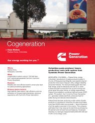
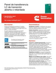
To set the default project parameters, select Projects from the top tool bar, then New<br />
Project Default Parameters at the bottom of the pull–down menu. The resulting dialog<br />
box, Figure A–1, shows New Project Parameters that are applied to all new projects and<br />
can be altered to suit your preferences. The project parameters for a single or an<br />
existing project can be changed without altering the default parameters by highlighting<br />
the project name then selecting Projects, Edit, and then the parameters tab.<br />
Following is an explanation of the project parameters and the default entries shown in the<br />
dialog box.<br />
Number of Generator Sets Running In Parallel<br />
The default value is 1. If the total load is greater than the capacity of a single generator<br />
set, insert 2, 3, or more as appropriate. If the total load is above 1000 kW, it may be<br />
advantageous to parallel generator sets for higher reliability and operational flexibility.<br />
When the total load is 300 kW or less, however, it is usually not cost–effective to parallel<br />
generator sets – although it is technically feasible.<br />
A–4 APPENDIX A<br />
Rev. Jan 2011
APPENDIX A<br />
Figure A–1. GenSize–New Project Parameters Dialog Box<br />
Rev. Jan 2011<br />
Application Manual – Liquid Cooled Generator Sets<br />
Minimum Genset Load/Capacity<br />
Running a generator set under light load can lead to engine damage and reduced<br />
generator set reliability. Cummins Power Generation does not recommend running<br />
generator sets at less than 30 percent of rated load –– this is the default setting in<br />
GenSize. Load banks should be used to supplement the regular loads when loading falls<br />
below the recommended value. A generator set should not run at less than 10 percent of<br />
rated load for any extended period.<br />
Maximum Voltage Dip (Starting and Peak)<br />
As you reduce the maximum allowable voltage dip during initial startup, or when loads<br />
cycle under automatic controls or have high peak surges, the size of the recommended<br />
generator set increases. Choosing a lower allowable voltage dip results in a larger<br />
recommended generator set. However, setting allowable voltage dips of more than 40<br />
percent can lead to relay and contactor malfunctions. The default Maximum Voltage Dip<br />
in GenSize is 35 percent.<br />
Maximum Frequency Dip<br />
As you reduce the maximum allowable frequency dip, you increase the size of the<br />
recommended generator set. Since a generator set is a limited power source (compared<br />
to a utility), voltage and frequency excursions will occur during transient loading events.<br />
The generator set must be sized to limit these excursions to an appropriate level for<br />
proper load performance. The default Maximum Frequency Dip in GenSize is 10 percent.<br />
This number may have to be set lower when supplying frequency–sensitive loads, such<br />
as UPS systems. Check with the UPS manufacturer for information on the UPS system’s<br />
sensitivity to frequency excursions when operating on a standby generator set.<br />
A–5
Application Manual – Liquid Cooled Generator Sets<br />
Altitude and Ambient Temperature<br />
Based on geographic location, the size of the generator set the software recommends<br />
may be increased for a given level of performance as altitude and/or ambient<br />
temperature increase. The default values are an altitude of 500 feet (152 meters) and an<br />
ambient temperature of 77° F (25° C).<br />
Sound Attenuation<br />
The default setting is None. However, a Quiet Site generator set may be selected. Quiet<br />
Site units include special exhaust silencers, a sheet metal housing with sound attenuating<br />
insulation, and/or intake and discharge dampers. Not all models are available in a Quiet<br />
Site configuration. When selecting Sound Attenuation, GenSize generator set<br />
recommendations will be limited to standard optional packages available from the factory.<br />
Your local distributor, however, should be consulted for any other sound attenuation<br />
needs.<br />
Maximum Alternator Temperature Rise<br />
A maximum allowable temperature rise over an ambient of 40° C (104° F) can be<br />
specified for the alternator windings. GenSize will recommend engine–alternator<br />
combinations that limit the alternator temperature rise to the specified temperature when<br />
powering the specified connected loads. It may be desirable to use lower temperature<br />
rise alternators in applications that contain significant non–linear loads, where better<br />
motor starting is required, or in prime duty applications. The default setting is 125° C.<br />
Note that, when you select a lower temperature rise alternator, you may increase the size<br />
of the recommended generator set to accommodate a larger alternator.<br />
Fuel<br />
The default fuel is Diesel. Other choices of available fuels are Natural gas and Liquid<br />
Propane Gas. An “Any Fuel” choice is available which allows GenSize to compare the<br />
performance of all available fuel choices.<br />
Note: For gaseous fuels requirements above approximately 150/140 kW, consult the distributor.<br />
Frequency<br />
Specify the required operating frequency. Generator sets are configured for either 50 Hz<br />
or 60 Hz. The default value is 60 Hz.<br />
Phase<br />
Select either a single– or three–phase generator set. The default setting is three–phase.<br />
If selecting single–phase, only single–phase loads are allowed. Selecting single–phase<br />
will also limit the number of available models since larger generator sets are not available<br />
with single–phase generators. The default three–phase selection permits single–phase<br />
loads but GenSize assumes that the single–phase loads will be balanced across the<br />
three phases.<br />
Duty<br />
GenSize makes a recommendation based on the standby or prime power rating of the<br />
generator set, derating appropriately for site conditions. The default setting is Standby.<br />
For further discussion and illustration of system and generator set ratings see Preliminary<br />
Design section.<br />
A standby power system is an independent power system that supplies a facility in the<br />
event of a failure of the normal power source. (It is assumed that the generator set is<br />
isolated from the utility service.) The standby power rating is applicable for emergency<br />
power duty for the duration of a typical power interruption. No overload capability is<br />
available for this rating.<br />
A prime power system is an independent power system for supplying electric power in<br />
lieu of purchasing power from a commercial utility. (It is assumed that the generator set<br />
is isolated from the utility service, or that utility service is unavailable.) The prime power<br />
rating is the maximum power available at variable load for an unlimited number of hours.<br />
A–6 APPENDIX A<br />
Rev. Jan 2011
Entering Loads<br />
Definition of Terms<br />
APPENDIX A<br />
Rev. Jan 2011<br />
Application Manual – Liquid Cooled Generator Sets<br />
A minimum of 10 percent overload capability is available for prime power ratings per<br />
engine rating standards BS 5514 and DIN 6271. Not every generator set configuration is<br />
available for prime duty.<br />
When generator sets are paralleled with a utility service for an extended period of time,<br />
they should not be operated in excess of their base load rating. Generally the base load<br />
rating of a generator set is significantly lower than its prime power rating. Base load<br />
ratings for generator sets are available from the factory or your local Cummins Power<br />
Generation distributor.<br />
Voltage<br />
Available voltage choices are a function of selected frequency. Default values are<br />
277/480, Series Wye.<br />
The next and most important step in sizing a generator set is identifying every type and<br />
size of load the generator set will power. As with most operations in GenSize, the loads<br />
can be entered either from the menu under Projects, Add New Load, or from the icons<br />
located on the tool bar. After selecting a load type, the load entry form will appear. Each<br />
load form will open with load characteristic defaults which can all be changed. Enter all of<br />
the required information. If you are unsure what any of the items are, check the online<br />
Help for an explanation. As each load is entered, they will appear in a list on the left side<br />
of the screen under the project you are working on. Selecting (with a mouse click) one of<br />
the loads in the list will display the load operating characteristics on the right of the<br />
screen. Double clicking a load icon will open the load entry form for that load and you<br />
can edit the load from here. The following is intended to help you understand load<br />
parameters and the way they are calculated by GenSize.<br />
Identify all of the different type and size loads the generator set will need to support. If<br />
you have more than one load of a given size and type, you only need to enter it once,<br />
unless you want each of the loads to carry a different description. The quantity of each<br />
load can be set when you enter the load in the step starting sequence. As described later<br />
in this section<br />
Cummins Power Generation has researched the starting and running characteristics of<br />
many of the common loads and have included defaults for these load characteristics in<br />
GenSize. You can choose to use the defaults or, if you know the characteristics of your<br />
load are different, change the load characteristic. If you have a load type other than what<br />
is identified in GenSize, use a miscellaneous load to define the load starting and running<br />
requirements.<br />
Based on the load characteristics, GenSize calculates values for running kW (RkW),<br />
running kVA (RkVA), starting kVA (SkVA), starting kW (SkW), starting power factor (SPF),<br />
peak kVA (PkVA), peak kW (PkW), and running amps (RAmps). When non–linear loads<br />
are present, it may be necessary to over–size the alternator, and GenSize calculates a<br />
value for the alternator kW (AkW) for the load.<br />
Note that when entering single–phase loads on a three–phase generator set, GenSize<br />
assumes that all three phase loads will be balanced among the three phases. Therefore,<br />
the single–phase loads are converted to an equivalent three–phase load for sizing<br />
purposes. This results in the single–phase load current being distributed across the three<br />
phases so the single–phase load current is divided by 1.73. When a single phase load is<br />
entered for a three phase set application, the actual single phase current will be displayed<br />
in the load entry form, but when the load is entered into a step (the step load is the<br />
balanced load applied to the generator), the step load current is converted to the<br />
equivalent three phase current.<br />
The following abbreviations are used in GenSize for calculating individual load running<br />
and starting requirements, step load requirements, and transient surge load<br />
requirements. These abbreviations are used on load forms and reports in the application<br />
and in the following discussion intended to document some of the calculations performed<br />
in GenSize.<br />
A–7
Application Manual – Liquid Cooled Generator Sets<br />
Load Running Requirements (Individual Load Steady–State Running)<br />
• Running kVA (RkVA) – the running kilovolt–amperes load.<br />
• Running kW (RkW) – the running kilowatt load.<br />
• Alternator kW (AkW) – the alternator capacity provided to compensate (to oversize)<br />
for non–linear distortion.<br />
• Running PF (RPF) – the steady–state running power factor of the load.<br />
• Efficiency – the ratio of output power to input power.<br />
• Running Amps (RAmps) – the running amperes for a load or step.<br />
Load Starting Requirements (Individual Load Starting)<br />
• Starting kW (SkW) – starting kilowatts of a load.<br />
• Starting kVA (SkVA)– starting kilovolt–amperes of a load.<br />
• Starting PF (SPF) – starting power factor is the power factor of the load at the time it<br />
is initially energized or started.<br />
Transient Step Load Requirements (Combined Load in Each Step Load Application)<br />
• Maximum Step kW – the maximum step load in kW (sum of individual load starting<br />
kilowatts (SkW)) in the step.<br />
• Maximum Step kVA – the maximum step load in kVA (sum of individual load starting<br />
kilovolt–amperes (SkVA)) in the step.<br />
• Cumulative Step kW – the Maximum Step kW added to the running kW of the previous<br />
step(s).<br />
• Cumulative Step kVA – the Maximum Step kVA added to the running kVA of the previous<br />
step(s).<br />
• Effective Step kW – the Cumulative Step kW times a multiplier to account for the<br />
reduced load effect due to sustained reduced output voltage during the transient step<br />
load.<br />
• Effective Step kVA – the Cumulative Step kVA times a multiplier to account for the<br />
reduced load effect due to sustained reduced output voltage during the transient step<br />
load.<br />
Transient Surge Load Requirements (Combined Load for all Loads that Require<br />
Random Peak Operating Power)<br />
• Peak kW (PkW) – the sudden increase of power in kW demanded by a cyclical load<br />
as it starts, or by other surge loads like welders and medical imaging equipment<br />
when they operate.<br />
• Peak kVA (PkVA) the sudden increase of power in kVA demanded by a cyclical load<br />
as it starts, or by other surge loads like welders and medical imaging equipment<br />
when they operate.<br />
• Cumulative Surge kVA – the Peak kVA added to the running kVA of all other non–<br />
surge loads.<br />
• Cumulative Surge kW – the Peak kW added to the running kW of all other non–surge<br />
loads.<br />
A–8 APPENDIX A<br />
Rev. Jan 2011
Detailed Load<br />
Calculations<br />
APPENDIX A<br />
Rev. Jan 2011<br />
Application Manual – Liquid Cooled Generator Sets<br />
• Effective Surge kW – the Cumulative Peak kW times a multiplier to account for the<br />
reduced load effect due to sustained reduced output voltage during the transient<br />
surge load.<br />
• Effective Surge kVA – the Cumulative Peak kVA times a multiplier to account for the<br />
reduced load effect due to sustained reduced output voltage during the transient<br />
surge load.<br />
The following documents all of the individual load requirements calculations. Load<br />
running, starting and peak surge requirements are calculated for each load based on<br />
assumed default operating characteristics as displayed on the individual load entry forms.<br />
Light Load Calculations<br />
Three different light load types can be entered:<br />
Fluorescent – A low–pressure mercury type discharge lamp where most of the light is<br />
emitted by an excited layer of fluorescent material. The same load characteristics are<br />
used for ballast or electronic types. Both are non–linear loads, but GenSize ignores the<br />
non–linearity for this load type since this is usually a small part of the total connected<br />
load.<br />
Incandescent – Standard bulb type lamp assemblies, which use a filament to create light.<br />
Discharge (HID) – Lamps that produce light by passing a current through a metal vapor;<br />
includes high pressure sodium, metal halide, and mercury vapor discharge lighting.<br />
RkW If kVA entered: RkW = kVA x RPF<br />
If Ramps entered: 1∅ RkW = (Ramps x voltage x RPF) ÷ 1000<br />
3∅ RkW = (Ramps x voltage x RPF x 1.73) ÷ 1000<br />
RkVA If RkW entered: RkVA = RkW ÷ RPF<br />
If Ramps entered: 1∅ RkVA = (Ramps x voltage) ÷ 1000<br />
3∅ RkVA = (Ramps x voltage x 1.73) ÷ 1000<br />
RPF Running power factor as entered or default<br />
SkW SkW = RkW for incandescence and florescence<br />
SkW = 0.75 x RkW for HID<br />
SkVA SkVA = SkW ÷ SPF<br />
SPF SPF = RPF, except for HID where default SPF = 0.85<br />
AkW AkW = RkW<br />
Ramps 1∅ Ramps = (RkW x 1000) ÷ (voltage x RPF)<br />
3∅ Ramps = (RkW x 1000) ÷ (voltage x RPF x 1.73)<br />
Air Conditioner Load Calculations<br />
GenSize simply converts tons to horsepower for sizing air conditioning loads at 2 HP/ton<br />
as a conservative estimate of the total load for a lower efficiency unit. If you want a more<br />
exact size and know the individual component motor loads in the A/C equipment, enter<br />
them individually and come up with a demand factor for what loads are likely to start<br />
simultaneously.<br />
RkW RkW = AC Tons x 2 x 0.746<br />
RkVA RkVA = RkW ÷ RPF<br />
RPF Running power factor as entered or default from database<br />
SkW High Inertia SkW = SkVA x SPF<br />
Low Inertia SkW = SkVA x SPF x 0.6<br />
SkVA SkVA = HP x (LRkVA/HP) x SkVA factor, where<br />
LRkVA/HP is the average kVA/HP for the NEMA Code letter of the motor,<br />
and SkVA factor is 1.0 for full voltage starting, or from reduced voltage<br />
starting table (see Reduced Voltage Starting Method)<br />
SPF As entered, or default values from database by HP and starting method<br />
For loads that are designated to automatically cycle on and off:<br />
A–9
Application Manual – Liquid Cooled Generator Sets<br />
PkW PkW = SkW<br />
PkVA PkVA = SkVA<br />
AkW (non–VFD) AkW = RkW except solid–state starter where<br />
AkW = 2.0 x RkW unless a bypass contactor is used, then AkW = RkW<br />
AkW (VFD) Conventional AC Inverter: AkW = 2.0 x RkW<br />
Pulse Width Modulated: AkW = 1.4 x RkW<br />
DC Drive: AkW = 2.0 x RkW<br />
Ramps 1∅ Ramps = (HP x 746) ÷ (voltage x Eff. x RPF)<br />
3∅ Ramps = (HP x 746) ÷ (1.73 x voltage x Eff. x RPF)<br />
Battery Charger Load Calculations<br />
A battery charger is a silicon–controlled rectifier (SCR) assembly used to charge<br />
batteries. A battery charger is a non–linear load requiring an oversized alternator.<br />
RkW RkW = RkVA x RPF<br />
RkVA RkVA = (Output kVA x Recharge Rate) ÷ Efficiency<br />
RPF Running power factor as entered or default<br />
SkW SkW = RkW<br />
SkVA SkVA = RkVA<br />
SPF SPF = RPF<br />
AkW For 3 pulse, AkW = 2.5 x RkW<br />
For 6 pulse, AkW = 1.4 x RkW<br />
For 12 pulse, AkW = 1.15 x RkW<br />
With input filter, AkW = 1.15 x RkW<br />
Ramps 1∅ Ramps = (RkVA x 1000) ÷ voltage<br />
3∅ Ramps = (RkVA x 1000) ÷ (voltage x 1.73)<br />
Medical Imaging Load Calculations<br />
GenSize calculates a peak voltage dip for when a medical imaging load is operated. This<br />
dip must be limited to 10% to protect the quality of the image. If the peak voltage dip is<br />
set higher in the project parameters, GenSize will automatically lower it and notify you.<br />
The generator set is then sized to limit the voltage dip to 10% when the medical imaging<br />
equipment is operated with all other loads running. If multiple medical image loads are<br />
used, the peak voltage dip is calculated for the single largest load and assumes only the<br />
single largest load will be operated at any one time.<br />
Note that GenSize assumes that the medical imaging equipment is not being operated<br />
while loads are starting, so the starting voltage dip is calculated separately and is allowed<br />
to exceed 10%.<br />
RkW If RkVA entered: RkW = RkVA x RPF<br />
If Ramps entered: 1∅ RkW = (Ramps x voltage x RPF) ÷ 1000<br />
3∅ RkW = (Ramps x voltage x RPF x 1.73) ÷ 1000<br />
RkVA If Ramps entered: RkVA = RkW ÷ RPF<br />
RPF Running power factor as entered or default<br />
SkW SkW = RkW<br />
SkVA SkVA = SkW ÷ SPF<br />
PkW PkW = PkVA x SPF<br />
PkVA As entered, or 1∅ PkVA = (Pamps x voltage) ÷ 1000<br />
3∅ PkVA = (Pamps x voltage x 1.73) ÷ 1000<br />
SPF SPF = SkVA ÷ SkW<br />
AkW AkW = RkW<br />
Ramps 1∅ Ramps = (RkVA x 1000) ÷ voltage<br />
3∅ Ramps = (RkVA x 1000) ÷ (voltage x 1.73)<br />
Motor Load Calculations<br />
If the motor load is powered by a variable speed or variable frequency drive or is an AC<br />
drive on a DC motor, select Variable Frequency Drive (VFD). A VFD is a non–linear load<br />
requiring an oversized alternator to match the running load requirements. On the other<br />
A–10 APPENDIX A<br />
Rev. Jan 2011
APPENDIX A<br />
Application Manual – Liquid Cooled Generator Sets<br />
hand, since VFDs ramp the load on, the starting requirements will be reduced compared<br />
to a motor started across the line. Select PWM if the VFD is of the pulse width modulated<br />
type. PWM type VFDs require less oversizing than non–PWM types.<br />
Motor starting requirements can be reduced by applying some type of reduced voltage or<br />
solid state starter. Application of these devices can result in smaller generator set<br />
recommendations. However, caution must be used when applying any of these starting<br />
methods. First of all, motor torque is a function of the applied voltage and all of these<br />
methods result in lower voltage during starting. These starting methods should only be<br />
applied to low inertia motor loads unless it can be determined the motor will produce<br />
adequate accelerating torque during starting. Additionally, these starting methods can<br />
produce very high inrush currents when they transition from start to run if the transition<br />
occurs prior to the motor reaching very near operating speed, resulting in starting<br />
requirements approaching an across the line start. GenSize assumes the motor reaches<br />
near rated speed before this transition, ignoring these potential inrush conditions. If the<br />
motor does not reach near rated speed prior to transition, excessive voltage and<br />
frequency dips can occur when applying these starters to generator sets. If unsure how<br />
your starter and load will react, use across–the–line starting.<br />
For across–the–line motor starting, select low inertia load if you know the load requires<br />
low starting torque at low speeds. This will reduce the starting kW requirements for the<br />
generator set and can result in a smaller set. Low inertia loads are typically centrifugal<br />
fans and pumps. If unsure, use high inertia (leave low inertia unselected).<br />
RkW If HP entered: RkW = (HP x 0.746) ÷ Running Efficiency<br />
If kW entered: RKW = kW ÷ Running Efficiency<br />
If Ramps entered: 1∅ RkW = (Ramps x voltage x RPF x Efficiency) ÷ 1000<br />
3∅ RkW = (Ramps x voltage x RPF x Efficiency x 1.73)<br />
÷ 1000<br />
RkVA RkVA = RkW ÷ RPF<br />
RPF Running power factor as entered or default from database<br />
SkW High Inertia SkW = SkVA x SPF<br />
Low Inertia SkW = SkVA x SPF x 0.6<br />
SkVA SkVA = HP x (LRkVA/HP) x SkVA factor, where LrkVA/HP is the average kVA/HP<br />
for the NEMA Code letter of the motor, and SkVA factor is 1.0 for full voltage<br />
starting, or from reduced voltage starting table (see Reduced Voltage Starting<br />
Method)<br />
SPF As entered, or default values from database by HP and starting method<br />
For loads that are designated to automatically cycle on and off:<br />
PkW PkW = SkW<br />
PkVA PkVA = SkVA<br />
AkW (non–VFD) AkW = RkW except solid–state starter where AkW = 2.0 x RkW<br />
unless a bypass contactor is used, then AkW = RkW<br />
AkW (VFD) Conventional AC Inverter: AkW = 2.0 x RkW<br />
Pulse Width Modulated: AkW = 1.4 x RkWDC Drive: AkW = 2.0 x RkW<br />
Ramps 1∅ Ramps = (HP x 746) ÷ (voltage x Efficiency x RPF)<br />
3∅ Ramps = (HP x 746) ÷ (1.73 x voltage x Efficiency x RPF)<br />
Fire Pump Load Calculations<br />
GenSize will size the generator limiting the peak voltage dip to 15% when starting the fire<br />
pump,with all other non–surge loads running. This is to meet North American fire code<br />
requirements. The generator set does not have to be sized to provide the locked rotor<br />
kVA of the fire pump motor indefinitely. That would result in an oversized generator set,<br />
which could experience maintenance and reliability issues from being under–utilized.<br />
Rev. Jan 2011<br />
A–11
Application Manual – Liquid Cooled Generator Sets<br />
Whenever a reduced voltage starter is used for a fire pump motor, the user should<br />
consider sizing for across–the–line starting because the fire pump controller includes<br />
either a manual–mechanical, manual–electrical, or automatic means to start the pump<br />
across–the–line in the case of a controller malfunction. GenSize will not disallow use of<br />
reduced voltage starters for fire pumps, however.<br />
RkW If HP entered: RkW = HP x 0.746 ÷ Running Efficiency<br />
If kW entered: RkW = kW ÷ Running Efficiency<br />
If Ramps entered: 1∅ RkW = (Ramps x voltage x RPF x Efficiency) ÷ 1000<br />
3∅ RkW = (Ramps x voltage x RPF x Efficiency x 1.73)<br />
÷ 1000<br />
RkVA RkVA = RkW ÷ RPF<br />
RPF Running power factor as entered or default from database<br />
SkW High Inertia SkW = SkVA x SPF<br />
Low Inertia SkW = SkVA x SPF x 0.6<br />
SkVA SkVA = HP x (LRkVA/HP) x SkVA factor, where LrkVA/HP is the average kVA/HP<br />
for the NEMA Code letter of the motor, and SkVA factor is 1.0 for full voltage<br />
starting, or from reduced voltage starting table (see Reduced Voltage Starting<br />
Method)<br />
SPF As entered, or default values from database by HP and starting method<br />
PkW PkW = SkW<br />
PkVA PkVA = SkVA<br />
AkW (non–VFD) AkW = RkW except solid–state starter where AkW = 2.0 x RkW<br />
unless a bypass contactor is used, then AkW = RkW<br />
AkW (VFD) Conventional AC Inverter: AkW = 2.0 x RkW<br />
Pulse Width Modulated: AkW = 1.4 x RkW<br />
DC Drive: AkW = 2.0 x RkW<br />
Ramps 1∅ Ramps = (HP x 746) ÷ (voltage x Efficiency x RPF)<br />
3∅ Ramps = (HP x 746) ÷ (1.73 x voltage x Efficiency x RPF)<br />
UPS Load Calculations<br />
A static UPS uses silicon controlled rectifiers (SCR) or another static device to convert<br />
AC voltage to DC for charging batteries, and an inverter to convert DC to conditioned AC<br />
power to supply the load. A UPS is a non–linear load and may require an oversized<br />
alternator. Some incompatibility problems between generator sets and static UPSs have<br />
led to many misconceptions about sizing the generator set for this type of load. Past<br />
problems did occur, and the recommendation from UPS suppliers at that time was to<br />
oversize the generator set from two to five times the UPS rating. Even then some<br />
problems persisted, and since then those incompatibility problems have been addressed<br />
by most UPS manufacturers. It is more cost effective to require generator compatibility of<br />
the UPS supplier than to oversize the generator.<br />
If the batteries are discharged when the UPS is operating on the generator set, the<br />
generator set must be capable of supplying the rectifier for battery charging and the<br />
inverter to supply the load. A second reason to use the full UPS rating is that additional<br />
UPS load may be added in the future up to the nameplate rating. The non–linear load<br />
sizing factors used by GenSize are based on the level of harmonics the UPS induces in<br />
the generator output with the UPS fully loaded. Since the harmonics increase at lighter<br />
loads, selecting the larger capacity alternator helps to offset this effect.<br />
For multiple redundant UPS systems, size the generator set for the combined nameplate<br />
ratings of the individual UPSs. Redundant system applications are those where one UPS<br />
is installed to back up another and the two are on–line at all times with 50% or less load.<br />
UPS equipment often has varying power quality requirements depending on the operating<br />
mode. When the rectifier is ramping up, often relatively broad frequency and voltage<br />
swings can occur without disrupting equipment operation. However, when the bypass is<br />
enabled, both frequency and voltage must be very constant, or an alarm condition will<br />
A–12 APPENDIX A<br />
Rev. Jan 2011
Miscellaneous<br />
Load Calculations<br />
APPENDIX A<br />
Rev. Jan 2011<br />
Application Manual – Liquid Cooled Generator Sets<br />
occur. This occurs when rapidly changing UPS input frequency results from a sudden<br />
transient load change on a generator set. During this transient event, static UPSs with<br />
solid–state bypass switches must break synch with the source and disable the bypass.<br />
RkW RkW = RkVA x RPF<br />
RkVA RkVA = (Output kVA x Recharge Rate) ÷ Efficiency<br />
RPF Running power factor as entered or default<br />
SkW SkW = RkW<br />
SkVA SkVA = RkVA<br />
SPF SPF = RPF<br />
AkW For 3 pulse, AkW = 2.5 x RkW<br />
For 6 pulse, AkW = 1.4 x RkW<br />
For 12 pulse, AkW = 1.1.5 x RkW<br />
With input filter, AkW = 1.15 x RkW for 6 and 12 pulse<br />
AkW = 1.40 x RkW for 3 pulse<br />
Ramps 1∅ Ramps = (RkVA x 1000) ÷ voltage<br />
3∅ Ramps = (RkVA x 1000) ÷ (voltage x 1.73)<br />
Described below are the types and calculations GenSize uses for the various<br />
miscellaneous loads:<br />
Welder Load Calculations<br />
RkW If RkVA entered: RkW = RkVA x RPF<br />
If Ramps entered: 1∅ RkW = (Ramps x voltage x RPF) ÷ 1000<br />
3∅ RkW = (Ramps x voltage x RPF x 1.73) ÷ 1000<br />
RkVA If Ramps entered: RkVA = RkW ÷ RPF<br />
RPF Running power factor as entered or default<br />
SkW SkW = RkW<br />
SkVA SkVA = SkW ÷ SPF<br />
PkW PkW = PkVA x SPF<br />
PkVA As entered, or 1∅ PkVA = (Pamps x voltage) ÷ 1000<br />
3∅ PkVA = (Pamps x voltage x 1.73) ÷ 1000<br />
SPF SPF = SkVA ÷ SkW<br />
AkW AkW = RkW<br />
Ramps 1∅ Ramps = (RkVA x 1000) ÷ voltage<br />
3∅ Ramps = (RkVA x 1000) ÷ (voltage x 1.73)<br />
General Receptacle Load Calculations<br />
RkW RkW = Entered kW<br />
RkVA RkVA = RkW ÷ RPF<br />
RPF Running power factor as entered or default<br />
SkW SkW = RkW<br />
SkVA SkVA = SkW ÷ SPF<br />
SPF SPF = RPF<br />
PkW PkW = RkW<br />
PkVA PkVA = RkVA<br />
AkW AkW = RkW<br />
Ramps 1∅ Ramps = (RkW x 1000) ÷ (voltage x RPF)<br />
3∅ Ramps = (RkW x 1000) ÷ (voltage x RPF x 1.73)<br />
User Defined Load Calculations<br />
RkW If kW entered: RkW = Kw<br />
If kVA entered: RkW = kVA x RPF<br />
If Ramps entered: 1∅ RkW = (Ramps x voltage x RPF) ÷ 1000<br />
3∅ RkW = (Ramps x voltage x RPF x 1.73) ÷ 1000<br />
RkVA If kW entered: RkVA = RkW ÷ RPF<br />
If RkVA entered: RkVA = kVA<br />
If Ramps entered: 1∅ RkVA = (Ramps x voltage) ÷ 1000<br />
3∅ RkVA = (Ramps x voltage x 1.73) ÷ 1000<br />
A–13
Application Manual – Liquid Cooled Generator Sets<br />
Entering Loads<br />
into Steps<br />
RPF Running power factor as entered or default<br />
SkW If kW entered: SkW = kW<br />
If kVA entered: SkW = SkVA x SPF<br />
If Starting amps entered:1∅ SkW = (Ramps x voltage x RPF) ÷ 1000<br />
3∅ SkW = (Ramps x voltage x RPF x 1.73) ÷ 1000<br />
SkVA SkVA = SkW ÷ SPF<br />
SPF SPF = RPF, except for HID where default SPF = 0.85 and RPF = 0.90<br />
PkW PkW = SkW<br />
PkVA PkVA = SkVA<br />
AkW AkW = RkW<br />
Ramps 1∅ Ramps = (RkW x 1000) ÷ (voltage x RPF)<br />
3∅ Ramps = (RkW x 1000) ÷ (voltage x RPF x 1.73)<br />
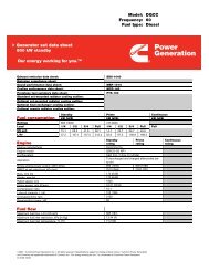
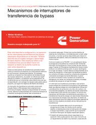
Figure A–2. GenSize Application Project Window<br />
After entering the loads, you need to enter all of the project loads into Load Steps. Open<br />
the first load step by clicking on the Steps folder on the left of the screen. Note that<br />
initially, there are no loads in the Step. Step sequence loading can reduce the size of<br />
generator set required when using multiple steps. Multiple transfer switches can be used<br />
to connect load to the generator set at different times, simply by adjusting the transfer<br />
time delays on the individual switches. Simply allow a few seconds between steps to<br />
allow the generator set to stabilize with each load step.<br />
To enter individual loads into the step, simply click and drag the load over the step. Once<br />
the load is placed into a step, you can set the load quantity in the step by right clicking<br />
and selecting Set Quantity from the drop down menu. Alternatively, each time you click<br />
and drag a load into the step, the quantity will increase.<br />
A–14 APPENDIX A<br />
Rev. Jan 2011
Load Step<br />
Considerations<br />
Step Sequence<br />
Guidelines<br />
Recommendations<br />
and Reports<br />
APPENDIX A<br />
Rev. Jan 2011<br />
Application Manual – Liquid Cooled Generator Sets<br />
To enter multiple loads into the step, click on the loads folder and all loads are listed on<br />
the right side of the screen. Using the Shift or Ctrl key and the mouse, select the desired<br />
loads, click on any of the selected loads on the right, and drag to the step. All of the<br />
selected loads should appear in the step.<br />
Use the tool bar to add one or more additional steps, as desired. You can view the loads<br />
and steps using View on the menu to find out either which steps individual loads were<br />
placed in or to get a summary of all the loads in each step.<br />
For many applications, the generator set will be sized to be able to pick up all of the loads<br />
in a single step. For some applications it is advantageous to start the loads with the<br />
larger starting surge requirements first, then after those loads are running, to start the<br />
rest of the loads in different steps. The starting sequence of loads might also be<br />
determined by codes in which the emergency loads must come on first, then the standby<br />
equipment, then the optional loads.<br />
Starting step sequencing of generator sets may be accomplished with transfer switches<br />
using transfer time delays, load sequencer, or other controller, such as a PLC. You may<br />
use this application to tell your distributor how many starting steps your application<br />
requires. Remember, even though there is a controlled initial loading sequence, there<br />
may be uncontrolled load stopping and starting of certain loads and you may wish to<br />
check surge loading under those conditions.<br />
Single Step Simultaneous Starting: One commonly used approach is to assume that all<br />
connected loads will be started in a single step, regardless of the number of transfer<br />
switches used. This assumption will result in the most conservative (largest) generator<br />
set selection. Use a single step load unless something will be added, such as multiple<br />
transfer switches with staggered time delays or a step load sequencer.<br />
Single Step with a Diversity Factor: This is similar to simultaneous starting in a single<br />
step, except that an estimated diversity factor, of perhaps 80%, is applied to reduce the<br />
SkVA and SkW totals to account for whatever automatic starting controls may be<br />
provided with the load equipment.<br />
Multiple Step Sequence: Sequenced starting of loads (where possible) will often permit<br />
the selection of a smaller generator set. GenSize assumes that adequate time is allowed<br />
between load steps for the generator set voltage and frequency to stabilize, typically 5–10<br />
seconds.<br />
Consider the following when controls or delays are provided to step sequence the loads<br />
onto the generator set:<br />
• Start the largest motor first.<br />
• When starting motors that use electronic drives (VFD or VSD) the largest motor first<br />
rule may not apply. Using electronic drives for starting and running motors allows the<br />
designer to better control the actual load applied to the generator set by controlling<br />
the maximum current load, rate of load application, etc. The thing to remember about<br />
these loads is that they are more sensitive to voltage variation than motors that are<br />
started ”across–the–line.”<br />
• Load the UPS last. UPS equipment is typically frequency sensitive, especially to the<br />
rate of change of frequency. A pre–loaded generator set will be more stable in<br />
accepting UPS load.<br />
• For each step, the SkW required is the total of the RkW of the previous step(s) plus<br />
the SkW for that step.<br />
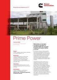
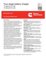
The following is intended to help you understand the GenSize recommendation for a<br />
generator set and available reports that can be printed. Figure A–3 illustrates the default<br />
screen on which GenSize makes its recommendation for the single Cummins Power<br />
Generation generator set model that most closely matches the current project<br />
A–15
Application Manual – Liquid Cooled Generator Sets<br />
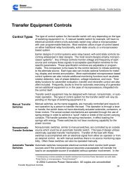
parameters. This screen can be toggled with the screen illustrated in Figure A–4 on<br />
which all generator set models that match the parameters can be viewed. You may find it<br />
helpful to view the latter display to appreciate the differences in performance between all<br />
of the models that could do the job, any of which you could select for the project. You<br />
can also print out Reports for distribution and review.<br />
The recommended model(s) will be highlighted in green in the upper half of the screen.<br />
In the lower half of the screen are displayed the parameters for the recommended<br />
generator set. These include:<br />
• Generator Set Requirements: This tab summarizes the Duty, Voltage, Altitude,<br />
Phase, Voltage Dips, and other parameters.<br />
• Load Running/Surge Requirements: This tab summarizes all of the load requirements<br />
for the project. Pct. Rated Load provides a quick way of determining how<br />
much generator set running capacity is being used.<br />
• Generator Set Configuration: This tab enumerates the alternator frame size, number<br />
of leads, whether the alternator is reconnectable, whether the alternator has an<br />
increased capacity for motor starting, the voltage range, whether the alternator has<br />
an extended stack, and whether the alternator can provide full single–phase output.<br />
It also lists the engine model, displacement, number of cylinders, fuel, and the altitude<br />
and ambient temperature derating knees and slope values.<br />
The report grid displays information about the recommended generator set and allows<br />
comparison with other generator sets. Following is a discussion of some of the important<br />
headings on this grid:<br />
Site Rated Standby (Prime) kW<br />
Displays the site rated standby or prime kW (prime power duty is already derated 10<br />
percent). If the display is red, the site rated kW is less than the load running kW, or the<br />
running load kW is less than 30 percent of the site rated set kW. A recommended<br />
generator set must meet the running load requirement and run at least 30 percent of<br />
rated capacity to be recommended.<br />
If the display is yellow, the load running kW is less than 30 percent of the site rated set<br />
kW. Running generator sets at less than 30 percent of rated load can be accomplished<br />
by lowering the minimum percent rated load value in the New Project Parameters.<br />
Site Rated Alternator Max kW (Temperature Rise)<br />
Displays the site–rated alternator kW for the temperature rise selected in the current<br />
project parameters. If the display is red, the alternator cannot maintain the temperature<br />
rise for your connected load requirement, either Running kW or Alternator kW.<br />
Site Rated Alternator Max kVA (Temperature Rise)<br />
Displays the site rated alternator kVA for the temperature rise set in the New Project<br />
Parameters. If the display/column is red, the alternator cannot maintain your temperature<br />
rise for the load Running kVA requirement. The maximum alternator rated kVA capacity<br />
is shown in the grid.<br />
The altitude knee for alternators, however, is 1000m (3280 ft) and the temperature knee<br />
40° C (104° F). Alternator Max kW will be derated 3% per 500m (1640 ft) of altitude<br />
above the knee and 3% per 5° C (9° F) of ambient temperature over the knee.<br />
A–16 APPENDIX A<br />
Rev. Jan 2011
APPENDIX A<br />
Rev. Jan 2011<br />
Application Manual – Liquid Cooled Generator Sets<br />
Figure A–3. Recommended Generator Set Window<br />
A–17
Application Manual – Liquid Cooled Generator Sets<br />
A–18 APPENDIX A<br />
Rev. Jan 2011<br />
Figure A–4. All Generator Set Window
APPENDIX A<br />
Application Manual – Liquid Cooled Generator Sets<br />
Site Rated Max SkW and Max SkVA<br />
Displays the site–rated (derated when necessary for altitude and ambient temperature)<br />
maximum SkW and SkVA the generator set configuration can accommodate. If the<br />
display is red, the generator set cannot recover to a minimum of 90 percent of rated<br />
voltage with required Step or Peak load. One of the sizing philosophies for surge loading<br />
is that, with the surge load applied, the generator set must be able to recover to 90<br />
percent of rated voltage so that motors can develop adequate accelerating torque. If the<br />
generator set recovers to 90 percent of rated voltage, a motor will develop 81 percent of<br />
rated torque, which has been shown by experience to provide acceptable motor starting<br />
performance.<br />
If the display is yellow, the generator set can recover to a minimum of 90 percent of rated<br />
voltage with required surge load, but only because the surge requirement has been<br />
reduced. GenSize will reduce the surge requirement in recognition of the fact that the<br />
generator set output voltage is reduced while loads having starting power requirements<br />
approaching the maximum generator set capacity are starting.<br />
Temperature Rise At Full Load<br />
Displays the temperature rise the alternator will not exceed while supplying load up to<br />
and including the generator set full–load rating. Each individual generator set model will<br />
have one or more of the following temperature rise alternators available which may be<br />
specified in the current project parameters: 80° C, 105°C, 125° C and 150° C. Of course,<br />
the actual temperature rise of an alternator is a function of actual connected load.<br />
Therefore, GenSize may recommend a generator set with a lower or higher temperature<br />
rise option than specified in the New Project Parameters since the set recommendation is<br />
based on connected load. Connected load may be less than the full generator set<br />
capacity or, in the case of non–linear loads, the alternator may be required to be rated at<br />
greater than the set capacity. In any case, the set recommendation will limit the<br />
alternator temperature rise to that specified in the New Project Parameters.<br />
Excitation<br />
Displays the type of excitation system to be supplied with a generator set. If the display<br />
is red, the generator set is shunt excited and the percentage of non–linear load exceeds<br />
25 percent of the load running requirement, RkW. The PMG excitation system is<br />
recommended for applications that have a high–linear load content. Unless the PMG<br />
option is unavailable, Cummins Power Generation does not recommend using shunt<br />
excited generator sets if the non–linear load requirement is more than 25 percent of the<br />
total load requirement.<br />
The non–linear load requirement is calculated by adding the Running kW from all of the<br />
loads where Alternator kW exceeds Running kW. This will be the case for UPS loads,<br />
variable frequency motors, and solid state motor starters which are not equipped with an<br />
automatic bypass. This Alternator kW sum is then divided by the sum of the Running kW<br />
from all of the loads.<br />
Why a generator set may not be recommended: Several factors can cause a generator<br />
set to not be recommended.<br />
• Running kW requirement may exceed the rating of the generator set. Project parameters<br />
such as altitude, ambient temperature and prime power duty may cause the<br />
generator set to be derated and fall below project requirements.<br />
• The Running kW may be below the minimum of 10 to 30 percent of rated generator<br />
set capacity, as specified in the current project parameters (30 percent is default, as<br />
recommended by Cummins Power Generation).<br />
• The surge kW requirement may exceed generator capacity, which may have fallen<br />
below project requirements because of derating for altitude and ambient temperature.<br />
GenSize uses the greater Cumulative kW and Peak kW to determine the load surge<br />
kW.<br />
Rev. Jan 2011<br />
A–19
Application Manual – Liquid Cooled Generator Sets<br />
• The surge kVA exceeds generator set capacity. The surge kVA requirement is similar<br />
to the surge kW requirement except that there is no derating for altitude or ambient<br />
temperature. GenSize uses the greater of cumulative kVA and Peak kVA (if any) to<br />
determine the load surge kVA requirement.<br />
• The alternator kW required exceeds the alternator capacity, which may be derated for<br />
altitude and ambient temperature by the project parameters. The altitude knee for<br />
alternators, however, is 1000m (3280 ft) and the temperature knee 40° C (104° F).<br />
Alternator kW will be derated 3% per 500m (1640 ft) of altitude above the knee and<br />
3% per 5° C (9° F) of ambient temperature over the knee.<br />
• The alternator kVA required exceeds alternator capacity, which can be derated by<br />
altitude and temperature in the same way as the alternator kW.<br />
• The total non–linear load requirement exceeds 25 percent of the total load requirement.<br />
This will exclude shunt–excited generators where PMG excitation is not available.<br />
The total non–linear load requirement is the sum of the Alternator kW values of<br />
all of the non–linear loads.<br />
• The calculated voltage and frequency dips exceed the limits set in the current project<br />
parameters.<br />
• Starting voltage dip is calculated using the higher of two values: dip based on the<br />
maximum Step kW or on the maximum step kVA.<br />
• Peak voltage dip is calculated only if loads in the project exhibit a running surge<br />
(cyclic loads or loads like medical imaging that have a high peak power requirement<br />
when they are operated.<br />
• Frequency dip is calculated using the higher of two values: maximum Step kW or<br />
Peak kW from loads which exhibit running surge.<br />
• The message, “No generator set is available that meets your running load requirements”<br />
usually means that something in the New Project Parameters has been<br />
changed after having specified the running load. For instance, you will get the message<br />
if you change from diesel to natural gas fuel or from no sound attenuation to<br />
Quite Site and the running load you had specified exceeds the capacity of the largest<br />
natural gas or Quite Site generator set available. It may also mean that your project<br />
falls into a “gap” in the Cummins Power Generation product line. At this point, lowering<br />
the minimum percent rated load in the project parameters could allow a recommended<br />
set. If this is the case, contact your local Cummins Power Generation distributor<br />
for help.<br />
• The message, “No generator set is available which meets your frequency or voltage<br />
dip requirements” generally means that the surge requirement of some load step is<br />
forcing selection of such a large generator set that the steady state running load falls<br />
below 30 percent of the generator set capacity. Since Cummins Power Generation<br />
does not recommend running at less than 30 percent of rated capacity, no set can be<br />
recommended. At this point, you may have several choices:<br />
• Increase the allowable voltage or frequency dip.<br />
• Reduce the minimum percent rated load to less than 30 percent.<br />
• Apply loads in more steps to lower the individual step surge load.<br />
• Provide reduced–voltage motor starting.<br />
• Parallel generator sets.<br />
• Add loads that do not have a high starting surge (lights, resistive loads, etc.).<br />
A–20 APPENDIX A<br />
Rev. Jan 2011
Reports<br />
APPENDIX A<br />
Rev. Jan 2011<br />
Application Manual – Liquid Cooled Generator Sets<br />
Several type of reports can be generated for the project that is open, a Step/Load Detail,<br />
Steps and Dips Detail, and a Recommended Generator report. These can be viewed on<br />
screen for review prior to completion, saved for submittal or printed. Figure A–5 is an<br />
example of the Recommended Generator report.<br />
Figure A–5. Recommended Generator Report in View Mode<br />
A–21
APPENDIX B CONTENTS<br />
APPENDIX B CONTENTS<br />
Rev. Jan 2011<br />
Application Manual – Liquid Cooled Generator Sets<br />
APPENDIX B . . . . . . . . . . . . . . . . . . . . . . . . . . . . . . . . . . . . . . . . . . . . . . B–2<br />
Reduced Voltage Motor Starting . . . . . . . . . . . . . . . . . . . . . . . . . . . . . . . . . . . . . . . B–2<br />
A Comparison of Motor Starting Methods . . . . . . . . . . . . . . . . . . . . . . . . . . . B–2<br />
Full Voltage Motor Starting . . . . . . . . . . . . . . . . . . . . . . . . . . . . . . . . . . . . . . . . B–2<br />
Autotransformer Motor Starting, Open Transition . . . . . . . . . . . . . . . . . . . . . B–3<br />
Autotransformer Motor Starting, Closed Transition . . . . . . . . . . . . . . . . . . . . B–3<br />
Reactor Motor Starting, Closed Transition . . . . . . . . . . . . . . . . . . . . . . . . . . . B–4<br />
Resistor Motor Starting, Closed Transition . . . . . . . . . . . . . . . . . . . . . . . . . . . B–4<br />
Star–Delta Motor Starting, Closed Transition . . . . . . . . . . . . . . . . . . . . . . . . . B–5<br />
Part Winding Motor Starting, Closed Transition . . . . . . . . . . . . . . . . . . . . . . . B–5<br />
Wound Rotor Motor Starting . . . . . . . . . . . . . . . . . . . . . . . . . . . . . . . . . . . . . . . B–6<br />
Synchronous Motor Starting . . . . . . . . . . . . . . . . . . . . . . . . . . . . . . . . . . . . . . . B–6<br />
General Application Note . . . . . . . . . . . . . . . . . . . . . . . . . . . . . . . . . . . . . . . . .<br />
B–6<br />
B–1
Application Manual – Liquid Cooled Generator Sets<br />
APPENDIX B<br />
Reduced<br />
Voltage Motor<br />
Starting<br />
A Comparison of<br />
Motor Starting<br />
Methods<br />
Full Voltage Motor<br />
Starting<br />
Although voltage dip often causes various problems, a controlled reduction in voltage at<br />
the motor terminals can be beneficial when it is used to reduce the starting kVA of a<br />
motor in applications where the reduced motor torque is acceptable. Reducing motor<br />
starting kVA can reduce the size of the required generator set, lessen the voltage dip, and<br />
provide a softer start for the motor loads. Make sure, however, that the motor will<br />
develop sufficient torque to accelerate the load under reduced voltage conditions. Also,<br />
any starter that makes a transition between “start” and “run” can cause an inrush<br />
condition nearly as severe as across–the–line starting –– unless the motor is at or near<br />
synchronous speed at transition. This may cause unacceptable voltage dip and<br />
potentially starter drop–out.<br />
Table B–1 compares the effects of full voltage, auto–transformer, and resistor starting on<br />
a 50 horsepower, Design B, Code G motor. As can be seen, autotransformer starting<br />
requires less motor starting capacity from the generator set. Resistor starting actually<br />
requires more kW (engine power) than across–the–line starting.<br />
% of applied voltage<br />
(tap)<br />
% of full voltage<br />
(multiplier) *<br />
Starting kVA with<br />
reduced voltage<br />
starter<br />
Starting kW with<br />
reduced voltage<br />
starter (kVA x PF)<br />
AUTOTRANS-<br />
FORMER<br />
TYPE OF STARTER<br />
RESISTOR FULL VOLTAGE<br />
65 50 100<br />
0.42 0.50 1.0<br />
295 ** x 0.42 = 123.9 295 ** x 0.50 = 147.5 295 ** x 1.0 = 295<br />
123.9 x 0.36***=<br />
43.4<br />
147.5 x 0.8****= 118 295x 0.36***= 106.9<br />
Run kVA 46 46 46<br />
Run kW 41 41 41<br />
* See Table 3–4<br />
** See Table 3–5 and multiply horsepower of 50 by the factor of 5.9 for Code Letter G.<br />
*** See Table 3–6<br />
**** See SPF for Resistor in Table 3–4<br />
Table B–1. Reduced Voltage Motor Starting Comparison<br />
Starting: Full voltage, across–the–line starting is typical unless it is necessary to reduce<br />
motor starting kVA because of the limited capacity of the generator set or to limit voltage<br />
dip during motor starting. There is no limit to the HP, size, voltage, or type of motor.<br />
Application Notes: This method is most common because of its simplicity, reliability, and<br />
initial cost. Note on the kVA and torque curves that starting kVA remains fairly constant<br />
until the motor almost reaches full speed. Also note that kW peaks at about 300 percent<br />
of rated kW near 80 percent of synchronous speed.<br />
B–2 APPENDIX B<br />
Rev. Jan 2011
LINE<br />
APPENDIX B<br />
3<br />
2<br />
1<br />
Autotransformer<br />
Motor Starting,<br />
Open Transition<br />
LINE<br />
MOTOR STARTING DIAGRAM<br />
MOTOR<br />
START: CLOSE 1–2–3<br />
RUN: NO CHANGE<br />
5<br />
4<br />
Autotransformer<br />
Motor Starting,<br />
Closed Transition<br />
Rev. Jan 2011<br />
kVA & TORQUE (% F. L.)<br />
600<br />
500<br />
400<br />
300<br />
200<br />
100<br />
Application Manual – Liquid Cooled Generator Sets<br />
TYPICAL TORQUE AND KVA CURVES FOR<br />
SQUIRREL CAGE INDUCTION MOTORS<br />
TORQUE<br />
KVA<br />
20 40 60 80 100<br />
SPEED (% SYNCHRONOUS)<br />
Starting: The autotransformer is in the circuit only during starting to reduce voltage to the<br />
motor. The opening of the circuit during transition can cause severe transients, which<br />
may even be able to cause nuisance tripping of circuit breakers.<br />
Application Notes: Open transition switching of reduced voltage starters should be<br />
avoided in generator set applications, especially when the motors are not brought up to<br />
full speed at the time of transition. The reason for this is that the motor slows down and<br />
gets out of synchronization during the switching transition. The result is similar to<br />
paralleling generator sets out of phase. The kVA drawn immediately after switching can<br />
exceed starting kVA. Also note that the starting power factor is lower when an<br />
autotransformer is used.<br />
MOTOR STARTING DIAGRAM<br />
8<br />
6<br />
3<br />
1<br />
7<br />
2<br />
MOTOR<br />
START: CLOSE 2–3–5–6–7<br />
RUN: OPEN 2–3–5–6–7; CLOSE 1–4–8<br />
kVA & TORQUE (% F. L.)<br />
600<br />
500<br />
400<br />
300<br />
200<br />
100<br />
TYPICAL TORQUE AND KVA CURVES FOR<br />
SQUIRREL CAGE INDUCTION MOTORS<br />
TORQUE<br />
KVA<br />
20 40 60 80 100<br />
SPEED (% SYNCHRONOUS)<br />
Starting: The circuit is not interrupted during starting. During transfer, part of the<br />
autotransformer winding remains in the circuit as a series reactor with the motor<br />
windings.<br />
Application Notes: Closed transition is preferred over open transition because of less<br />
electrical disturbance. The switching, however, is more expensive and complex. It is the<br />
most commonly used reduced voltage starting method for large motors with low load<br />
torque requirements, such as sewage lift pumps and chillers. The principle advantage is<br />
more torque per current than with other reduced voltage starting methods. Operation can<br />
be automatic and/or remote. Also note that the starting power factor is lower when an<br />
autotransformer is used.<br />
B–3
LINE<br />
Application Manual – Liquid Cooled Generator Sets<br />
MOTOR STARTING DIAGRAM<br />
5<br />
4<br />
3<br />
2<br />
1<br />
Reactor Motor<br />
Starting, Closed<br />
Transition<br />
LINE<br />
MOTOR<br />
START: CLOSE 6–7–2–3–4<br />
TRANSFER: OPEN 6–7<br />
RUN: CLOSE 1–5<br />
MOTOR STARTING DIAGRAM<br />
3<br />
2<br />
1<br />
Resistor Motor<br />
Starting, Closed<br />
Transition<br />
6<br />
5<br />
4<br />
7<br />
6<br />
START: CLOSE 1–2–3<br />
RUN: CLOSE 4–5–6<br />
kVA & TORQUE (% F. L.)<br />
B–4 APPENDIX B<br />
Rev. Jan 2011<br />
600<br />
500<br />
400<br />
300<br />
200<br />
100<br />
TYPICAL TORQUE AND KVA CURVES FOR<br />
SQUIRREL CAGE INDUCTION MOTORS<br />
TORQUE<br />
KVA<br />
20 40 60 80 100<br />
SPEED (% SYNCHRONOUS)<br />
Starting: Reactor starting has the advantage of simplicity and closed transition, but<br />
results in lower starting torque per kVA than with autotransformer starting. Relative<br />
torque, however, improves as the motor accelerates.<br />
Application Notes: Reactor starting is generally not used except for large, high–voltage<br />
or high–current motors. The reactors must be sized for HP and voltage and may have<br />
limited availability. Typically, reactor starting costs more than autotransformer starting for<br />
smaller motors, but is simpler and less expensive for larger motors. Starting power factor<br />
is exceptionally low. Reactor starting allows a smooth start with almost no observable<br />
disturbance on transition and is well suited for applications such as centrifugal pumps or<br />
fans.<br />
MOTOR<br />
kVA & TORQUE (% F. L.)<br />
600<br />
500<br />
400<br />
300<br />
200<br />
100<br />
TYPICAL TORQUE AND KVA CURVES FOR<br />
SQUIRREL CAGE INDUCTION MOTORS<br />
KVA<br />
TORQUE<br />
20 40 60 80 100<br />
SPEED (% SYNCHRONOUS)<br />
Starting: Resistor starting is occasionally used for smaller motors where several steps of<br />
starting are required and no opening of motor circuits between steps is allowed.<br />
Application Notes: Also available as a stepless transition starter which provides a<br />
smoother start. Resistor starting is usually the least expensive with small motors.<br />
Accelerates loads faster because the voltage increases with a decrease in current. Has a<br />
higher starting power factor.
LINE<br />
3<br />
2<br />
1<br />
APPENDIX B<br />
MOTOR STARTING DIAGRAM<br />
6<br />
5<br />
4 7<br />
Star–Delta Motor<br />
Starting, Closed<br />
Transition<br />
LINE<br />
START: CLOSE 1–2–3<br />
SECOND STEP: CLOSE 4–5–6<br />
THIRD STEP: CLOSE 7–8–9<br />
MOTOR STARTING DIAGRAM<br />
3<br />
2<br />
1<br />
9<br />
8<br />
MOTOR<br />
START: CLOSE 1–2–3–4–5–6<br />
RUN: OPEN 4–5–6; CLOSE 7–8–9<br />
Part Winding<br />
Motor Starting,<br />
Closed Transition<br />
7<br />
9<br />
MOTOR<br />
kVA & TORQUE (% F. L.)<br />
Rev. Jan 2011<br />
600<br />
500<br />
400<br />
300<br />
200<br />
100<br />
Application Manual – Liquid Cooled Generator Sets<br />
TYPICAL TORQUE AND KVA CURVES FOR<br />
SQUIRREL CAGE INDUCTION MOTORS<br />
TORQUE<br />
KVA<br />
20 40 60 80 100<br />
SPEED (% SYNCHRONOUS)<br />
Starting: Star–Delta starting requires no autotransformer, reactor, or resistor. The motor<br />
starts star–connected and runs delta–connected.<br />
Application Notes: This starting method is becoming more popular where low starting<br />
torques are acceptable. It has the following disadvantages:<br />
1. Open transition. Closed transition is available at extra cost.<br />
2. Low torque.<br />
3. No advantage when the motor is powered by a generator set unless the motor reaches<br />
synchronous speed before switching. In applications where the motor does not reach<br />
synchronous speed, the generator set must be sized to meet the surge.<br />
4 5 6<br />
8<br />
kVA & TORQUE (% F. L.)<br />
600<br />
500<br />
400<br />
300<br />
200<br />
100<br />
TYPICAL TORQUE AND KVA CURVES FOR<br />
SQUIRREL CAGE INDUCTION MOTORS<br />
TORQUE<br />
KVA<br />
20 40 60 80 100<br />
SPEED (% SYNCHRONOUS)<br />
Starting: Part winding starting is less expensive because it requires no autotransformer,<br />
reactor, or resistor and uses simple switching. Available in two or more starting steps<br />
depending on size, speed, and voltage of motor.<br />
Application Notes: Automatically provides closed transition. First, one winding is<br />
connected to the line; after a time interval, the second winding is paralleled with the first.<br />
Starting torque is low and is fixed by the motor manufacturer. The purpose of part<br />
winding is not to reduce starting current but to provide starting current in smaller<br />
increments. There is no advantage to this method if the motor is powered by a generator<br />
set unless the motor can reach synchronous speed before transition to the line.<br />
B–5
LINE<br />
Application Manual – Liquid Cooled Generator Sets<br />
MOTOR STARTING DIAGRAM<br />
3<br />
2<br />
1<br />
START: CLOSE 1–2–3<br />
RUN: CLOSE 4–5–6<br />
Wound Rotor<br />
Motor Starting<br />
LINE<br />
4<br />
6<br />
5<br />
4<br />
MOTOR<br />
MOTOR STARTING DIAGRAM<br />
5<br />
3<br />
2<br />
1<br />
6<br />
7<br />
RESISTORS<br />
Synchronous<br />
Motor Starting<br />
General<br />
Application Note<br />
8<br />
9<br />
kVA & TORQUE (% F. L.)<br />
B–6 APPENDIX B<br />
Rev. Jan 2011<br />
600<br />
500<br />
400<br />
300<br />
200<br />
100<br />
TYPICAL TORQUE AND KVA CURVES FOR<br />
SQUIRREL CAGE INDUCTION MOTORS<br />
TORQUE<br />
KVA<br />
20 40 60 80 100<br />
SPEED (% SYNCHRONOUS)<br />
Starting: A wound rotor motor can have the same starting torque as a squirrel cage<br />
motor but with less current. It differs from squirrel cage motors only in the rotor. A<br />
squirrel cage motor has short circuit bars, whereas a wound rotor motor has windings,<br />
usually three–phase.<br />
Application Notes: Starting current, torque, and speed characteristics can be changed by<br />
connecting the proper amount of external resistance into the rotor. Usually, wound rotor<br />
motors are adjusted so that the starting kVA is about 1.5 times running kVA. This is the<br />
easiest type of motor for a generator set to start.<br />
MOTOR<br />
ROTOR<br />
kVA & TORQUE (% F. L.)<br />
600<br />
500<br />
400<br />
300<br />
200<br />
TYPICAL TORQUE AND KVA CURVES FOR<br />
WOUND ROTOR MOTORS<br />
100<br />
START: CLOSE 1–2–3<br />
TORQUE<br />
STEP #1: CLOSE 4–5<br />
STEP #2: cLOSE 6–7<br />
20 40 60 80 100<br />
RUN: CLOSE 4–5–6<br />
SPEED (% SYNCHRONOUS)<br />
Starting: Synchronous motors can use most of the starting methods discussed.<br />
Synchronous motors rated 20 HP and greater have starting characteristics similar to<br />
wound rotor motors.<br />
Application Notes: Synchronous motors are in a class by themselves. There are no<br />
standards for performance, frame size, or connections. Motors rated 30 HP or less have<br />
high locked rotor currents. They can be used in applications where power factor<br />
correction is desired. (Use the standard code letter when the actual letter is not known.)<br />
If the reduced voltage motor starter has a time or rate adjustment, adjust the settings to<br />
obtain about two seconds between taps. This allows time for the motor to approach rated<br />
speed and thus reduce the peak kVA at the time of switching, as shown below. Note that<br />
at the minimum setting there is not much improvement over full voltage starting.<br />
In some applications the inrush current is so low that the motor shaft will not start to turn<br />
on the first tap, nor even the second. For those applications there is little reduction of<br />
starting kVA from the standpoint of the generator set.<br />
KVA
APPENDIX B<br />
FULL–VOLTAGE<br />
KVA CURVE<br />
kVA (% F. L.)<br />
600<br />
500<br />
400<br />
300<br />
200<br />
100<br />
KVA PEAK AT MINIMUM<br />
TIME OR RATE SETTING<br />
OF STARTER<br />
20 40 60 80 100<br />
SPEED (% SYNCHRONOUS)<br />
Rev. Jan 2011<br />
Application Manual – Liquid Cooled Generator Sets<br />
KVA PEAK AT MAXIMUM<br />
TIME OR RATE SETTING<br />
OF STARTER<br />
B–7
APPENDIX C CONTENTS<br />
APPENDIX C CONTENTS<br />
Rev. Jan 2011<br />
Application Manual – Liquid Cooled Generator Sets<br />
APPENDIX C . . . . . . . . . . . . . . . . . . . . . . . . . . . . . . . . . . . . . . . . . . . . . . C–2<br />
World Voltages and Supplies . . . . . . . . . . . . . . . . . . . . . . . . . . . . . . . . . . . . . . . . . .<br />
C–2<br />
C–1
Application Manual – Liquid Cooled Generator Sets<br />
APPENDIX C<br />
World<br />
Voltages and<br />
Supplies<br />
C–2 APPENDIX C<br />
Rev. Jan 2011
Country Frequency<br />
(Hz)<br />
APPENDIX C<br />
Supply Voltage<br />
Levels in Common<br />
Use (V)<br />
Abu Dhabi<br />
(United Arab Emirates) 50 415/250<br />
Afghanistan 50;60 380/220;220<br />
Algeria 50 10 kV; 5.5 kV;<br />
380/220; 220/127<br />
Angola 50 380/220; 220<br />
Antigua 60 400/230;230<br />
Argentina 50 13.2 kV;<br />
6.88 kV; 390/225;<br />
Australia<br />
Austria<br />
50<br />
50<br />
339/220;220<br />
22 kV; 11 kV;<br />
6.6 kV; 440/250;<br />
415/240; 240<br />
20 kV; 10 kV; 5 kV;<br />
380/220; 220<br />
Bahamas 60 415/240; 240/120;<br />
208/120; 120<br />
Bahrain 50;60 11 kV; 400/230;<br />
380/220;230;<br />
220/110<br />
Bangladesh 50 11 kV; 400/230; 230<br />
Barbados 50 11 kV; 3.3 kV;<br />
230/115; 200/115<br />
Belgium 50 15 kV; 6kV;<br />
380/220; 220/127, 220<br />
Belize 60 440/220; 220/110<br />
Bermuda 60 4.16/2.4 kV;<br />
240/120; 208/120<br />
Bolivia 50;60 230/115;<br />
400/230/220/110<br />
Botswana 50 380/220;220<br />
Brazil 50;60 13.8 kV; 11.2 kV;<br />
380/220, 220/127<br />
Brunei 50 415/230<br />
Bulgaria 50 20 kV; 15 kV;<br />
380/220; 220<br />
Burma 50 11 kV; 6.6 kV;<br />
400/230; 230<br />
Burundi<br />
Cambodia<br />
(Khmer Republic)<br />
50 380/220; 208/120;<br />
120<br />
Cameroon 50 15 kV; 320/220;<br />
220<br />
Canada 60 12.5/7.2 kV;<br />
600/347; 240/120;<br />
208/120; 600;<br />
480; 240<br />
Canary Islands 50 380/220; 230<br />
Cape Verde Islands 50 380/220; 127/220<br />
Cayman Islands 60 480/240; 480/227;<br />
240/120; 208/120<br />
Central African Republic 50 380/220<br />
Chad 50 380/220; 220<br />
China 50 380/220 50Hz<br />
Chile 50 380/220; 220<br />
Colombia 60 13.2 kV; 240/120;<br />
120<br />
Costa Rica 60 240/120; 120<br />
Cuba 60 440/220; 220/110<br />
Cyprus 50 11 kV; 415/240;<br />
240<br />
Czechoslovakia 50 22 kV; 15 kV; 6 kV;<br />
3 kV; 380/220; 220<br />
Dahomey 50 15 kV; 380/220;<br />
220<br />
Denmark<br />
Dominica<br />
50 30 kV; 10 kV;<br />
380/220;220<br />
(Windward Islands) 50 400/230<br />
Dominican Republic 60 220/100; 110<br />
Dubai (United Arab 50 6.6 kV; 330/220;<br />
Emirates)<br />
220<br />
Ecuador 60 240/120; 208/120;<br />
220/127; 220/110<br />
Rev. Jan 2011<br />
Application Manual – Liquid Cooled Generator Sets<br />
Country Frequency<br />
(Hz)<br />
Supply Voltage<br />
Levels in Common<br />
Use (V)<br />
Egypt (United Arab 50 11 kV; 6.6 kV;<br />
Republic)<br />
380/220; 220<br />
Eire (Republic of<br />
Ireland)<br />
50 10 kV; 380/220; 220<br />
El Salvador 60 14.4 kV; 2.4 kV;<br />
240/120<br />
Ethiopia<br />
Faeroe Islands<br />
50 380/220; 220<br />
(Denmark) 50 380/220<br />
Falkland Islands (UK) 50 415/230; 230<br />
Fiji 50 11 kV; 415/240;<br />
240<br />
Finland 50 660/380; 500;<br />
380/220; 220<br />
France 50 20 kV; 15 kV;<br />
380/220; 380; 220; 127<br />
French Guiana 50 380/220<br />
French Polynesia 60 220; 100<br />
Gabon 50 380/220<br />
Gambia 50 400/230; 230<br />
Germany (BRD) 50 20 kV; 10 kV; 6 kV;<br />
380/220; 220<br />
Germany (DDR) 50 10 kV; 6kV;<br />
660/380; 380/220;<br />
220/127; 220; 127<br />
Ghana 50 440/250; 250<br />
Gibraltar 50 415/240<br />
Greece 50 22 kV; 20 kV;<br />
15 kV; 6.6 kV;<br />
380/220<br />
Greenland 50 380/220<br />
Grenada (Windward<br />
Islands)<br />
50 400/230; 230<br />
Guadeloupe 50;60 20 kV; 380/220; 220<br />
Guam (Mariana Islands) 60 13.8 kV; 4 kV;<br />
480/277; 480;<br />
240/120; 207/120<br />
Guatemala 60 13.8 kV; 240/120<br />
Guyana 50 220/110<br />
Haiti 60 380/220; 230/115;<br />
230; 220; 115<br />
Honduras 60 220/110; 110<br />
Hong Kong (and<br />
50 11 kV;<br />
Kowloon)<br />
346/200; 200<br />
Hungary 50 20 kV; 10 kV;<br />
380/220; 220<br />
Iceland 50 380/220; 220<br />
India 50; 25 22 kV; 11kV;<br />
440/250; 400/230;<br />
460/230; 230<br />
Indonesia 50 380/220; 2201127<br />
Iran 50 20 kV; 11kV;<br />
400/231; 380/220;<br />
220<br />
Iraq 50 11 kV; 380/220; 220<br />
Israel 50 22kV; 12.6 kV;<br />
6.3 kV; 400/230;<br />
230<br />
Italy 50 20 kV; 15 kV;<br />
10 kV; 380/220;<br />
220/127; 220<br />
Ivory Coast 50 380/220; 220<br />
Jamaica 50 4/2.3 kV; 220/110<br />
Japan 50; 60 6.6 kV;200/100;<br />
22 kV; 6.6 kV;<br />
210/105; 200/100; 100<br />
Jordan 50 380/220; 220<br />
Kenya 50 415/240; 240<br />
Korea Republic (South) 60 200/100; 100<br />
Kuwait 50 415/240; 240<br />
Laos 50 380/220<br />
Lebanon 50 380/220; 190/110;<br />
220; 110<br />
Lesotho 50 380/220; 220<br />
Liberia 60 12.5/7.2 kV;<br />
416/240; 240/120;<br />
208/120<br />
C–3
Application Manual – Liquid Cooled Generator Sets<br />
Country Frequency<br />
(Hz)<br />
Supply Voltage<br />
Levels in Common<br />
Use (V)<br />
Libyan Arab Republic 50 400/230; 220/127;<br />
230; 127<br />
Luxembourg 50 20 kV; 15 kV;<br />
380/220; 220<br />
Manila 60 20 kV; 6.24 kV;<br />
3.6 kV; 240/120<br />
Martinique 50 220/127; 127<br />
Mauritania 50 380/220<br />
Mauritius 50 400/230; 230<br />
Macao 50 380/220; 220/110<br />
Malagassy Republic 50 5 kV; 380/220;<br />
(Madagascar)<br />
220/127<br />
Malawi 50 400/230; 230<br />
Malaysia (West) 50 415/240; 240<br />
Mali 50 380/220; 220/127;<br />
220; 127<br />
Malta 50 415/240<br />
Mexico 60 13.8 kV; 13.2 kV;<br />
480/277; 220/127;<br />
220/120<br />
Monaco 50 380/220; 220/127;<br />
220; 127<br />
Montserrat 60 400/230; 230<br />
Morocco 50 380/220; 220/127<br />
Mozambique 50 380/220<br />
Muscat and Oman 50 415/240; 240<br />
Naura 50 415/240<br />
Nepal 50 11 kV; 400/220; 220<br />
Netherlands 50 10 kV; 3 kV;<br />
380/220; 220<br />
Netherlands Antilles 50; 60 380/220; 230/115;<br />
220/127; 208/120<br />
New Caledonia 50 220<br />
New Zealand 50 11 kV; 415/240;<br />
400/230; 440;<br />
240; 230<br />
Nicaragua 60 13.2 kV; 7.6 kV;<br />
240/120<br />
Niger 50 380/220; 220<br />
Negeria 50 15 kV; 11 kV;<br />
400/230; 380/220;<br />
230; 220<br />
Norway 50 20 kV; 10 kV; 5 kV;<br />
380/220; 230<br />
Pakistan 50 400/230<br />
Panama 60 12 kV; 480/227;<br />
240/120; 208/120<br />
Papua New Guinea 50 22 kV; 11 kV;<br />
415/240; 240<br />
Paraguay 50 440/220; 380/220; 220<br />
Peru 60 10 kV; 6 kV; 225<br />
Philippines 60 13.8 kV; 4.16 kV;<br />
2.4 kV; 220/110<br />
Poland 50 15 kV; 6 kV;<br />
380/220; 220<br />
Portugal 50 15 kV; 5 kV;<br />
380/220; 220<br />
Portuguese Guinea 50 380/220<br />
Puerto Rico 60 8.32 kV; 4.16 kV;<br />
480; 240/120<br />
Qatar 50 415/240; 240<br />
Reunion 50 110/220<br />
Romania 50 20 kV; 10 kV; 6 kV;<br />
380/220; 220<br />
Rwanda 50 15 kV; 6.6 kV;<br />
380/220; 220<br />
Sabah 50 415/240; 240<br />
Sarawak (East<br />
Malaysia)<br />
50 415/240; 240<br />
Saudi Arabia 60 380/220; 220/127; 127<br />
Senegal 50 220/127; 127<br />
Seychelles 50 415/240<br />
Sierra Leone 50 11 kV; 400/230;<br />
230<br />
Singapore 50 22 kV; 6.6 kV;<br />
400/230; 230<br />
Country Frequency<br />
(Hz)<br />
Supply Voltage<br />
Levels in Common<br />
Use (V)<br />
Somali Republic 50 440/220; 220/110;<br />
230; 220; 110<br />
South Africa 50; 25 11 kV; 6.6 kV;<br />
3.3 kV; 433/250;<br />
400/230; 380/220;<br />
500; 220<br />
Southern Yemen (Aden) 50 400/230<br />
Spain 50 15 kV; 11 kV;<br />
380/220; 220/127;<br />
220; 127<br />
Spanish Sahara 50 380/220; 110; 127<br />
Sri Lanka (Ceylon) 50 11 kV; 400/230;<br />
230<br />
St. Helena 50 11 kV; 415/240<br />
St. Kitts Nevis Anguilla 50 400/230; 230<br />
St. Lucia 50 11 kV; 415/240;<br />
240<br />
Saint Vincent 50 3.3 kV; 400/230; 230<br />
Sudan 50 415/240; 240<br />
Surinam 50; 60 230/115; 220/127;<br />
220/110; 127; 115<br />
Swaziland 50 11 kV; 400/230; 230<br />
Sweden 50 20 kV; 10 kV; 6 kV;<br />
380/220; 220<br />
Switzerland 50 16 kV; 11 kV; 6 kV;<br />
380/220; 220<br />
Syrian Arab Republic 50 380/220; 200/115;<br />
Taiwan (Republic of<br />
China)<br />
220; 115<br />
60 22.8 kV;<br />
11.4 kV; 380/220;<br />
220/110<br />
50 11 kV; 400/230<br />
Tanzania (Union<br />
Republic of)<br />
Thailand 50 380/220; 220<br />
Togo 50 20 kV; 5.5 kV;<br />
380/220; 220<br />
Tonga 50 11 kV; 6.6 kV;<br />
415/240; 240; 210<br />
Trinidad and Tobago 60 12kV; 400/230;<br />
230/115<br />
Tunisia 50 15 kV; 10 kV;<br />
380/220; 220<br />
Turkey 50 15 kV; 6.3 kV;<br />
380/220; 220<br />
Uganda 50 11 kV 415/240; 240<br />
United Kingdom 50 22 kV; 11 kV;<br />
6.6 kV; 3.3 kV;<br />
400/230; 380/220;<br />
240; 230; 220<br />
Upper–Yolta 50 380/220; 220<br />
Uruguay 50 15 kV; 6 kV; 220<br />
USA 60 480/277; 208/120;<br />
240/120<br />
USSR 50 380/230; 220/127<br />
and higher voltages<br />
Venezuela 60 13.8 kV; 12.47 kV;<br />
4.8 kV; 4.16 kV;<br />
2.4 kV; 240/120;<br />
208/120<br />
Vietnam (Republic of) 50 15 kV; 380/220;<br />
208/120; 220; 120<br />
Virgin Islands (UK) 60 208; 120<br />
Virgin Islands (US) 60 110/220<br />
Western Samoa 50 415/240<br />
Yemen, Democratic<br />
(PDR)<br />
50 440/250; 250<br />
Yugoslavia 50 10 kV; 6.6 kV;<br />
380/220; 220<br />
Zaire (Republic of) 50 380/220; 220<br />
Zambia 50 400/230; 230<br />
Zimbabwe 50 11 kV; 390/225; 225<br />
C–4 APPENDIX C<br />
Rev. Jan 2011
APPENDIX D CONTENTS<br />
APPENDIX D CONTENTS<br />
Rev. Jan 2011<br />
Application Manual – Liquid Cooled Generator Sets<br />
APPENDIX D . . . . . . . . . . . . . . . . . . . . . . . . . . . . . . . . . . . . . . . . . . . . . . D–2<br />
Useful Formulas . . . . . . . . . . . . . . . . . . . . . . . . . . . . . . . . . . . . . . . . . . . . . . . . . . . . .<br />
D–2<br />
D–1
Application Manual – Liquid Cooled Generator Sets<br />
APPENDIX D<br />
Useful<br />
Formulas<br />
TO OBTAIN: SINGLE–PHASE AC POW-<br />
ER<br />
kilowatts (kW) Volts x Amps x PF<br />
1000<br />
kVA Volts x Amps<br />
1000<br />
Amps p ( (kVA unknown) )<br />
Amps p (kW ( unknown) )<br />
Frequency q y (Hertz) ( )<br />
kW x 1000<br />
Volts x PF<br />
kVA x 1000<br />
Volts<br />
# poles x rpm<br />
120<br />
THREE–PHASE AC POW-<br />
ER<br />
VoltsxAmpsxPFx1.732<br />
1000<br />
Volts x Amps x 1.732<br />
1000<br />
kW x 1000<br />
Volts x PF x 1.732<br />
kVA x 1000<br />
Volts x 1.732<br />
# poles x rpm<br />
120<br />
Reactive Power ( (kVAR) )<br />
– –<br />
Volts x Amps x 1 PF2 � Volts x Amps x 1.732 x 1 PF<br />
1000<br />
2 �<br />
1000<br />
% Voltage g regulation g<br />
(f (for steady t d loads, l d from f<br />
No–Load to Full–Load)<br />
–<br />
�<br />
–<br />
VNL VFL � x 100<br />
V FL � x 100 � V NL V FL<br />
% Frequency q y Regulation g<br />
– –<br />
(f (for steady t d loads l d from f<br />
No–Load to Full–Load) �FNL FFL � x 100<br />
Horsepower p required q<br />
tto ddrive i a generator t<br />
kW<br />
0.746 X Generator Efficiency<br />
First cycle y RMS short cir-<br />
cuit it<br />
current (±10%)<br />
D–2 APPENDIX D<br />
Rev. Jan 2011<br />
V FL<br />
F FL � x 100 � F NL F FL<br />
Rated Amperes<br />
pu X��d<br />
F FL<br />
kW<br />
0.746 X Generator Efficiency<br />
Rated Amperes<br />
pu X��d<br />
• “PF” refers to power factor, which is expressed as a decimal fraction. For example,<br />
80% power factor = 0.8 for the purposes of calculations. In general, single–phase<br />
generator sets are rated at 100% power factor and three–phase generator sets at<br />
80% power factor.<br />
• “Volts” refers to line–to–line voltage.<br />
• “Amps” refers to line current in amperes.<br />
• “F” refers to frequency. 0% frequency regulation is defined as isochronous.
APPENDIX E CONTENTS<br />
APPENDIX E CONTENTS<br />
Rev. Jan 2011<br />
Application Manual – Liquid Cooled Generator Sets<br />
APPENDIX E . . . . . . . . . . . . . . . . . . . . . . . . . . . . . . . . . . . . . . . . . . . . . . E–2<br />
Maintenance and Service . . . . . . . . . . . . . . . . . . . . . . . . . . . . . . . . . . . . . . . . . . . . . E–2<br />
Daily . . . . . . . . . . . . . . . . . . . . . . . . . . . . . . . . . . . . . . . . . . . . . . . . . . . . . . . . . . . E–2<br />
Weekly . . . . . . . . . . . . . . . . . . . . . . . . . . . . . . . . . . . . . . . . . . . . . . . . . . . . . . . . . E–2<br />
Monthly . . . . . . . . . . . . . . . . . . . . . . . . . . . . . . . . . . . . . . . . . . . . . . . . . . . . . . . . . E–2<br />
Semi–Annually . . . . . . . . . . . . . . . . . . . . . . . . . . . . . . . . . . . . . . . . . . . . . . . . . . E–3<br />
Annually . . . . . . . . . . . . . . . . . . . . . . . . . . . . . . . . . . . . . . . . . . . . . . . . . . . . . . . .<br />
E–3<br />
E–1
Application Manual – Liquid Cooled Generator Sets<br />
APPENDIX E<br />
Maintenance<br />
and Service<br />
Daily<br />
Weekly<br />
Monthly<br />
A well–planned program of preventative maintenance and service should be integral to<br />
the design of an on–site power system. Failure of a standby generator set to start and<br />
run could lead to loss of life, personal injury, property damage, and loss of business<br />
income. Failure to start and run due to low battery charge because of improper<br />
maintenance is the most common type of failure. A comprehensive program carried out<br />
on a scheduled basis by qualified persons can prevent such failures and their possible<br />
consequences. The maintenance and service programs most generator set distributors<br />
offer on a contract basis should be considered. Typically, they include performance of<br />
scheduled maintenance, repairs, parts replacement, and service documentation.<br />
The maintenance schedule for prime power sets should be on the basis of running time,<br />
as published by the manufacturer. Since standby sets run infrequently, the maintenance<br />
schedule is usually in terms of daily, weekly, monthly, or longer term tasks. See the<br />
manufacturer’s instructions for details. In any case, scheduled maintenance should<br />
include:<br />
• Check for oil, coolant, and fuel leaks.<br />
• Check operation of the engine coolant heater(s). If the block is not warm, the heaters<br />
are not working and the engine might not start.<br />
• Check to see that the switchgear is in the AUTOMATIC position and the generator<br />
circuit breaker, if used, is closed.<br />
• Check engine oil and coolant levels.<br />
• Check the battery charging system.<br />
• Check for air cleaner restrictions.<br />
• Exercise the generator set by starting and running it for at least 30 minutes under not<br />
less than 30% rated load. Lower load levels are acceptable if the exhaust gas temperature<br />
reaches a level sufficient to prevent engine damage. See Table E–1 for<br />
minimum exhaust gas temperatures for Cummins engines. Check for unusual vibrations,<br />
noises, and exhaust, coolant and fuel leaks while the set is running. (Regular<br />
exercising keeps engine parts lubricated, improves starting reliability, prevents oxidation<br />
of electrical contacts, and consumes fuel before it deteriorates and has to be discarded.)<br />
• Check for radiator restrictions, coolant leaks, deteriorated hoses, loose and deteriorated<br />
fan belts, non–functioning motorized–louvers and proper concentration of<br />
engine coolant additives.<br />
• Check for holes, leaks, and loose connections in the air cleaner system.<br />
• Check fuel level and fuel transfer pump operation.<br />
• Check for exhaust system leaks and restrictions, and drain the condensate trap.<br />
• Check all meters, gauges, and indicator lamps for proper operation.<br />
• Check the battery cable connections and battery fluid level and recharge the batteries<br />
if specific gravity is less than 1.260.<br />
• Check for ventilation restrictions in the inlet and outlet openings of the generator.<br />
E–2 APPENDIX E<br />
Rev. Jan 2011
Semi–Annually<br />
Annually<br />
APPENDIX E<br />
• Check that all required service tools are readily available.<br />
Engne Family<br />
Exhaust Stack Temperatures<br />
Calibrated Thermocouple<br />
B Series 550<br />
C Series 600<br />
LTA10 650<br />
M11 650<br />
NT(A)855 650<br />
N14 650<br />
QSX15 700<br />
KTA19 650<br />
VTA28 650<br />
QST30 650<br />
KTA38 650<br />
QSK45 700<br />
KTA50 700<br />
QSK60 700<br />
QSK178 700<br />
Rev. Jan 2011<br />
Application Manual – Liquid Cooled Generator Sets<br />
Table E–1. Recommended Minimum Exhaust Stack Temperatures. (Exhaust gas temperature is<br />
measured by thermocouple. Use of external temperature sensing is not sufficiently accureate to<br />
verify exhaust temperature.)<br />
• Change engine oil filters.<br />
• Change the filter(s) in the coolant conditioner circuit.<br />
• Clean or replace the crankcase breather filter(s).<br />
• Change the fuel filter(s), drain sediment from fuel tanks, check flexible fuel hoses for<br />
cuts and abrasions and check the governor linkage.<br />
• Check electrical safety controls and alarms.<br />
• Clean up accumulations of grease, oil, and dirt on the generator set.<br />
• Check power distribution wiring, connections, circuit breakers, and transfer switches.<br />
• Simulate a utility power outage. This will test the ability of the set to start and<br />
assume the rated load. Check the operation of the automatic transfer switches,<br />
related switchgear and controls, and all other components in the standby power system.<br />
• Check the fan hub, pulleys, and water pump.<br />
• Clean the day tank breather.<br />
• Check and torque the exhaust manifold and turbocharger fasteners.<br />
• Tighten the generator set mounting hardware.<br />
• Clean the generator power output and control boxes. Check for and tighten all loose<br />
wiring connectors. Measure and record generator winding insulation resistances.<br />
Check the operation of the generator heater strips and grease the bearings.<br />
E–3
Application Manual – Liquid Cooled Generator Sets<br />
• Check the operation of the main generator circuit breaker (if used) by manually operating<br />
it. Test the trip unit according to the manufacturer’s instructions.<br />
• If the set is normally exercised at no–load or carries only light loads, run the generator<br />
set for at least three hours, including one hour at near rated load.<br />
• Conduct generator insulation tests annually throughout the life of the generator set.<br />
Initial tests done before final load connections are made will serve as benchmarks for<br />
annual tests. These tests are mandatory for generator sets rated above 600 VAC.<br />
Review ANSI/IEEE Standard 43, Recommended Practice for Testing Insulation<br />
Resistance of Rotating Machinery.<br />
E–4 APPENDIX E<br />
Rev. Jan 2011
APPENDIX F CONTENTS<br />
APPENDIX F CONTENTS<br />
Rev. Jan 2011<br />
Application Manual – Liquid Cooled Generator Sets<br />
APPENDIX F . . . . . . . . . . . . . . . . . . . . . . . . . . . . . . . . . . . . . . . . . . . . . . F–2<br />
Codes and Standards . . . . . . . . . . . . . . . . . . . . . . . . . . . . . . . . . . . . . . . . . . . . . . . . F–2<br />
Related Product Standards . . . . . . . . . . . . . . . . . . . . . . . . . . . . . . . . . . . . . . . . F–2<br />
Modification of Products . . . . . . . . . . . . . . . . . . . . . . . . . . . . . . . . . . . . . . . . . .<br />
F–2<br />
F–1
Application Manual – Liquid Cooled Generator Sets<br />
APPENDIX F<br />
Codes and<br />
Standards<br />
Related Product<br />
Standards<br />
Modification of<br />
Products<br />
Applicable performance standards for generator sets include:<br />
• International Electrotechnical Committee: Standard for Rotating Electrical Machines,<br />
Part 1 (Rating and Performance), IEC 34–1.<br />
• International Standards Organization: Standard for Reciprocating Internal Combustion<br />
Engine Driven Alternating Current Generator Sets, Parts 1 through 9, ISO 8528.<br />
• National Electrical Manufacturer’s Association: Standard for Motors and Generators,<br />
NEMA MG1–1.<br />
• Canadian Standards Association: CSA 22, Canadian Electrical Code. CSA 282,<br />
Emergency Electrical Power Supply for Buildings.<br />
• Underwriters Laboratories: UL 2200 Stationary Engine Generator Assemblies.<br />
In North America, many safety (and environmental) issues related to generator set<br />
applications are addressed by the following standards of the National Fire Protection<br />
Association (NFPA):<br />
• Flammable and Combustible Liquids Code–NFPA 30<br />
• Standard for the Installation and use of Stationary Combustion Engines and Gas Turbines–NFPA<br />
37<br />
• National Fuel Gas Code–NFPA 54<br />
• Storage and Handling of Liquified Petroleum Gas—NFPA 58<br />
• National Electrical Code–NFPA 70<br />
• Health Care Facilities Code–NFPA 99<br />
• Life Safety Code–NFPA 101<br />
• Emergency and Standby Power Systems–NFPA 110.<br />
Generator sets and other related products are sometimes Certified, Listed, or otherwise<br />
assured to be compliant to specific standards or codes. This generally applies to the<br />
product as manufactured and shipped from the original manufacturer. Often these<br />
products are labeled or in some way marked as such. Subsequent modifications to the<br />
product could alter or violate the specific code compliance or listing. Product<br />
modifications should be, and in some cases must be submitted to the local authority<br />
having jurisdiction for approval.<br />
F–2 APPENDIX F<br />
Rev. Jan 2011
APPENDIX G CONTENTS<br />
APPENDIX G CONTENTS<br />
Rev. Jan 2011<br />
Application Manual – Liquid Cooled Generator Sets<br />
APPENDIX G . . . . . . . . . . . . . . . . . . . . . . . . . . . . . . . . . . . . . . . . . . . . . . G–2<br />
Glossary . . . . . . . . . . . . . . . . . . . . . . . . . . . . . . . . . . . . . . . . . . . . . . . . . . . . . . . . . . .<br />
G–2<br />
G–1
Application Manual – Liquid Cooled Generator Sets<br />
APPENDIX G<br />
Glossary<br />
AC (Alternating Current)<br />
Alternating current is electric current that alternates between a positive maximum value<br />
and a negative maximum value at a characteristic frequency, usually 50 or 60 cycles per<br />
second (Hertz).<br />
AC Generator<br />
AC generator is the preferred term for referring to a generator that produces alternating<br />
current (AC). See Alternator and Generator.<br />
Acoustic Material<br />
Acoustic material is any material considered in terms of its acoustic properties, especially<br />
its properties of absorbing or deadening sound.<br />
Active Power<br />
Active power is the real power (kW) supplied by the generator set to the electrical load.<br />
Active power creates a load on the set’s engine and is limited by the power of the engine<br />
and efficiency of the generator. Active power does the work of heating, lighting, turning<br />
motor shafts, etc.<br />
Air Circuit Breaker<br />
An air circuit breaker automatically interrupts the current flowing through it when that<br />
current exceeds the trip rating of the breaker. Air is the medium of electrical insulation<br />
between electrically live parts and grounded (earthed) metal parts. Also see Power<br />
Circuit Breaker.<br />
Annunciator<br />
An annunciator is an accessory device used to give remote indication of the status of an<br />
operating component in a system. Annunciators are typically used in applications where<br />
the equipment monitored is not located in a portion of the facility that is normally<br />
attended. The NFPA has specific requirements for remote annunciators used in some<br />
applications, such as hospitals.<br />
Alternator<br />
Alternator is another term for AC generator.<br />
Amortisseur Windings<br />
The amortisseur windings of a synchronous AC generator are the conductors embedded<br />
in the pole faces of the rotor. They are connected together at both ends of the poles by<br />
end rings. Their function is to dampen waveform oscillations during load changes.<br />
Ampacity<br />
Ampacity is the safe current–carrying capacity of an electrical conductor in amperes as<br />
defined by code.<br />
Ampere<br />
The ampere is a unit of electric current flow. One ampere of current will flow when a<br />
potential of one volt is applied across a resistance of one ohm.<br />
Apparent Power<br />
Apparent power is the product of current and voltage, expressed as kVA. It is real power<br />
(kW) divided by the power factor (PF).<br />
Armature<br />
The armature of an AC generator is the assembly of windings and metal core laminations<br />
in which the output voltage is induced. It is the stationary part (stator) in a revolving–field<br />
generator.<br />
G–2 APPENDIX G<br />
Rev. Jan 2011
APPENDIX G<br />
Application Manual – Liquid Cooled Generator Sets<br />
Authority Having Jurisdiction<br />
The authority having jurisdiction is the individual with the legal responsibility for inspecting<br />
a facility and approving the equipment in the facility as meeting applicable codes and<br />
standards.<br />
Backup Protection<br />
Backup protection consists of protective devices which are intended to operate only after<br />
other protective devices have failed to operate or detect a fault.<br />
Base Load<br />
Base load is that portion of a building load demand which is constant. It is the “base” of<br />
the building demand curve.<br />
Black Start<br />
Black start refers to the starting of a power system with its own power sources, without<br />
assistance from external power supplies.<br />
Bumpless Transition<br />
Bumpless transition is make–before–break transfer of an electrical load from one source<br />
to another where voltage and frequency transients are kept to a minimum.<br />
Bus<br />
Bus can refer to the current–carrying copper bars that connect the AC generators and<br />
loads in a paralleling system, to the paralleled output of the AC generators in a system or<br />
to a feeder in an electrical distribution system.<br />
Circuit<br />
A circuit is a path for an electric current across a potential (voltage).<br />
Circuit Breaker<br />
A circuit breaker is a protective device that automatically interrupts the current flowing<br />
through it when that current exceeds a certain value for a specified period of time. See<br />
Air Circuit Breaker, Main Breaker, Molded Case Circuit Breaker, and Power Circuit<br />
Breaker.<br />
Contactor<br />
A contactor is a device for opening and closing an electric power circuit.<br />
Continuous Load<br />
A continuous load is a load where the maximum current is expected to continue for three<br />
hours or more (as defined by the NEC for design calculations).<br />
Cross Current Compensation<br />
Cross current compensation is a method of controlling the reactive power supplied by AC<br />
generators in a paralleling system so that they share equally the total reactive load on the<br />
bus without significant voltage droop.<br />
CT (Current Transformer)<br />
Current transformers are instrument transformers used in conjunction with ammeters,<br />
control circuits and protective relaying. They usually have 5 ampere secondaries.<br />
Current<br />
Current is the flow of electric charge. Its unit of measure is the ampere.<br />
Current Limiting Fuse<br />
A current limiting fuse is a fast–acting device that, when interrupting currents in its<br />
current–limiting range, will substantially reduce the magnitude of current, typically within<br />
one–half cycle, that would otherwise flow.<br />
Rev. Jan 2011<br />
G–3
Application Manual – Liquid Cooled Generator Sets<br />
Cycle<br />
A cycle is one complete reversal of an alternating current or voltage—from zero to a<br />
positive maximum to zero again and then from zero to a negative maximum to zero<br />
again. The number of cycles per second is the frequency.<br />
dB/dB(A) Scale<br />
The decibel (dB) scale used in sound level measurements is logarithmic. Sound level<br />
meters often have several decibel weighting scales (A, B,C). The A–scale, dB(A), is the<br />
most commonly used weighting scale for measuring the loudness of noise emitted from<br />
generator sets.<br />
Delta Connection<br />
Delta connection refers to a three–phase connection in which the start of each phase is<br />
connected to the end of the next phase, forming the Greek letter Δ.. The load lines are<br />
connected to the corners of the delta.<br />
Demand Factor<br />
The demand factor is the ratio of actual load to the potential total connected load.<br />
Deviation Factor<br />
The deviation factor is the maximum instantaneous deviation, in percent, of the generator<br />
voltage from a true sine wave of the same RMS value and frequency.<br />
Dielectric Strength<br />
Dielectric strength is the ability of insulation to withstand voltage without rupturing.<br />
Direct Current (DC)<br />
Direct current is current with no reversals in polarity.<br />
Differential Relay<br />
A differential relay is a protective device which is fed by current transformers located at<br />
two different series points in the electrical system. The differential relay compares the<br />
currents and picks up when there is a difference in the two which signifies a fault in the<br />
zone of protection. These devices are typically used to protect windings in generators or<br />
transformers.<br />
Earthing<br />
Earthing is the intentional connection of the electrical system or electrical equipment<br />
(enclosures, conduit, frames, etc.) to earth or ground.<br />
Efficiency (EFF)<br />
Efficiency is the ratio of energy output to energy input, such as the ratio between the<br />
electrical energy input to a motor and the mechanical energy output at the shaft of the<br />
motor.<br />
Emergency System<br />
An emergency system is independent power generation equipment that is legally required<br />
to feed equipment or systems whose failure may present a life safety hazard to persons<br />
or property.<br />
Energy<br />
Energy is manifest in forms such as electricity, heat, light and the capacity to do work. It<br />
is convertible from one form to another, such as in a generator set, which converts<br />
rotating mechanical energy into electrical energy. Typical units of energy are kW•h, BTU<br />
(British thermal unit), Hp•h, ft•lbf, joule, and calorie.<br />
Exciter<br />
An exciter is a device that supplies direct current (DC) to the field coils of a synchronous<br />
generator, producing the magnetic flux required for inducing output voltage in the<br />
armature coils (stator). See Field.<br />
G–4 APPENDIX G<br />
Rev. Jan 2011
APPENDIX G<br />
Application Manual – Liquid Cooled Generator Sets<br />
Fault<br />
A fault is any unintended flow of current outside its intended circuit path in an electrical<br />
system.<br />
Field<br />
The generator field (rotor) consists of a multi–pole electromagnet which induces output<br />
voltage in the armature coils (stator) of the generator when it is rotated by the engine.<br />
The field is energized by DC supplied by the exciter.<br />
Flicker<br />
A term describing visible brightening and dimming of lights caused by a voltage surge or<br />
oscillation.<br />
Free Field (Noise Measurements)<br />
In noise measurements, a free field is a field in a homogeneous, isotropic medium (a<br />
medium having the quality of transmitting sound equally in all directions) which is free of<br />
boundaries. In practice, it is a field in which the effects of the boundaries are negligible in<br />
the region of interest. In the free field, the sound pressure level decreases 6 dB each<br />
doubling of the distance from a point source.<br />
Frequency<br />
Frequency is the number of complete cycles per unit of time of any periodically varying<br />
quantity, such as alternating voltage or current. It is usually expressed as (Hz) Hertz or<br />
CPS (cycles per second).<br />
Frequency Regulation<br />
Frequency regulation is a measure that states the difference between no–load and<br />
full–load frequency as a percentage of full–load frequency.<br />
Generator<br />
A generator is a machine which converts rotating mechanical energy into electrical<br />
energy. See AC generator.<br />
GFP (Ground Fault Protection)<br />
A ground fault protection system is a system designed to limit the damage to equipment<br />
from line–to–ground fault currents.<br />
Governor<br />
A governor is a device on the engine which controls fuel to maintain a constant engine<br />
speed under various load conditions. The governor must have provision for adjusting<br />
speed (generator frequency) and speed droop (no load to full load).<br />
Ground<br />
A ground is a connection, either intentional or accidental, between an electrical circuit and<br />
the earth or some conducting body serving in place of the earth.<br />
Grounding<br />
Grounding is the intentional connection of the electrical system or the electrical<br />
equipment (enclosures, conduit, frames etc.) to earth.<br />
Grounded Neutral<br />
A grounded neutral is the intentionally grounded center point of a Y–connected, four–wire<br />
generator, or the mid–winding point of a single phase generator.<br />
Ground Return<br />
Ground return is a method of ground fault detection that employs a single sensor (CT)<br />
encircling the main bonding jumper between the power system neutral and ground. This<br />
device in itself is not capable of locating the faulted circuit but when used in conjunction<br />
with ground fault sensors on all feeders and source connections, can provide bus fault<br />
protection when properly coordinated (delayed).<br />
Rev. Jan 2011<br />
G–5
Application Manual – Liquid Cooled Generator Sets<br />
Harmonics<br />
Harmonics are voltage or current components which operate at integral multiples of the<br />
fundamental frequency of a power system (50 or 60 Hertz). Harmonic currents have the<br />
effect of distorting the shape of the voltage wave form from that of a pure sine wave.<br />
Hertz (Hz)<br />
The term Hertz is the preferred designation for cycles per second (CPS).<br />
Hunting<br />
Hunting is a phenomenon that can occur upon load changes in which the frequency or<br />
the voltage continues to rise above and fall below the desired value without reaching a<br />
steady–state value. It is caused by insufficient damping.<br />
Insulation<br />
Insulation is non–conductive material used to prevent leakage of electric current from a<br />
conductor. There are several classes of insulation in use for generator construction, each<br />
recognized for a maximum continuous–duty temperature.<br />
Jerk<br />
Rate of change of acceleration. Often used as a measure of performance in elevator<br />
systems.<br />
kVA (kilo–Volt–Amperes)<br />
kVA is a term for rating electrical devices. A device’s kVA rating is equal to its rated<br />
output in amperes multiplied by its rated operating voltage. In the case of three–phase<br />
generator sets, kVA is the kW ouput rating divided by 0.8, the rated power factor. KVA is<br />
the vector sum of the active power (kW) and the reactive power (kVAR) flowing in a<br />
circuit.<br />
kVAR (kilo–Volt–Amperes Reactive)<br />
KVAR is the product of the voltage and the amperage required to excite inductive circuits.<br />
It is associated with the reactive power which flows between paralleled generator<br />
windings and between generators and load windings that supply the magnetizing currents<br />
necessary in the operation of transformers, motors, and other electromagnetic loads.<br />
Reactive power does not load the generator set’s engine but does limit the generator<br />
thermally.<br />
kW (kilo–Watts)<br />
KW is a term used for power rating electrical devices and equipment. Generator sets in<br />
the United States are usually rated in kW. KW, sometimes called active power, loads the<br />
generator set’s engine.<br />
kW• h (kilo–Watt–hour)<br />
This is a unit of electric energy. It is equivalent to one kW of electric power supplied for<br />
one hour.<br />
Lagging Power Factor<br />
Lagging power factor in AC circuits (a power factor of less than 1.0) is caused by<br />
inductive loads, such as motors and transformers, which cause the current to lag behind<br />
the voltage. See Power Factor.<br />
Leading Power Factor<br />
Leading power factor in AC circuits (0.0 to –1.0) is caused by capacitive loads or<br />
overexcited synchronous motors which cause the current to lead the voltage. See Power<br />
Factor.<br />
Leg<br />
A leg is a phase winding of a generator, or a phase conductor of a distribution system.<br />
Line–To–Line Voltage<br />
Line–to–line voltage is the voltage between any two phases of an AC generator.<br />
G–6 APPENDIX G<br />
Rev. Jan 2011
APPENDIX G<br />
Application Manual – Liquid Cooled Generator Sets<br />
Line–To–Neutral Voltage<br />
In a 3–phase, 4–wire, Y–connected generator, line–to–neutral voltage is the voltage<br />
between a phase and the common neutral where the three phases are tied together.<br />
Load Factor<br />
The load factor is the ratio of the average load to the generator set power rating.<br />
Low Voltage<br />
In the context of this manual, low voltage refers to AC system operating voltages from<br />
120 to 600 VAC.<br />
Lugging<br />
Attaching lugs (terminations) to the end of wires.<br />
Main Breaker<br />
A main breaker is a circuit breaker at the input or output of the bus, through which all of<br />
the bus power must flow. The generator main breaker is the device, usually mounted on<br />
the generator set, that can be used to interrupt generator set power output.<br />
Mains<br />
Mains is a term used extensively outside the United States to describe the normal power<br />
service (utility).<br />
Medium Voltage<br />
In the context of this manual, medium voltage refers to AC system operating voltages<br />
from 601 to 15,000 VAC.<br />
Molded Case Circuit Breaker<br />
A molded case circuit breaker automatically interrupts the current flowing through it when<br />
the current exceeds a certain level for a specified time. Molded case refers to the use of<br />
molded plastic as the medium of electrical insulation for enclosing the mechanisms and<br />
for separating conducting surfaces from one another and from grounded (earthed) metal<br />
parts.<br />
Motoring<br />
In paralleling applications, unless a generator set is disconnected from the bus when its<br />
engine fails (usually as a result of a fuel system problem), the generator will drive (motor)<br />
the engine, drawing power from the bus. Reverse power protection which automatically<br />
disconnects a failed set from the bus is essential for paralleling systems. Also, in certain<br />
applications such as elevators, the load can motor the generator set if insufficient<br />
additional load is present.<br />
NEC (National Electrical Code)<br />
This document is the most commonly referenced general electrical standard in the United<br />
States.<br />
NEMA<br />
National Electrical Manufacturers Association<br />
Neutral<br />
Neutral refers to the common point of a Y–connected AC generator, a conductor<br />
connected to that point or to the mid–winding point of a single–phase AC generator.<br />
NFPA<br />
National Fire Protection Association<br />
Nonattainment Areas<br />
Areas of the country that consistently do not meet U.S. Environmental Protection Agency<br />
(EPA) air quality standards.<br />
Rev. Jan 2011<br />
G–7
Application Manual – Liquid Cooled Generator Sets<br />
Nonlinear Load<br />
A nonlinear load is a load for which the relationship between voltage and current is not a<br />
linear function. Some common nonlinear loads are fluorescent lighting, SCR motor<br />
starters, and UPS systems. Nonlinear loads cause abnormal conductor heating and<br />
voltage distortion.<br />
Octave Band<br />
In sound pressure measurements (using an octave band analyzer), octave bands are the<br />
eight divisions of the measured sound frequency spectrum, where the highest frequency<br />
of each band is twice that of its lowest frequency. The octave bands are specified by<br />
their center frequencies, typically: 63, 125, 250, 500, 1,000, 2,000, 4,000 and 8,000 Hz<br />
(cycles per second).<br />
Ohm<br />
The ohm is a unit of electrical resistance. One volt will cause a current of one ampere to<br />
flow through a resistance of one ohm.<br />
One–Line Diagram<br />
A one–line diagram is a schematic diagram of a three–phase power distribution system<br />
which uses one line to show all three phases. It is understood when using this easy to<br />
read drawing that one line represents three.<br />
Out–Of–Phase<br />
Out–of–phase refers to alternating currents or voltages of the same frequency which are<br />
not passing through their zero points at the same time.<br />
Overload Rating<br />
The overload rating of a device is the load in excess of the nominal rating the device can<br />
carry for a specified length of time without being damaged.<br />
Overshoot<br />
Overshoot refers to the amount by which voltage or frequency exceeds the nominal value<br />
as the voltage regulator or governor responds to changes in load.<br />
Parallel Operation<br />
Parallel operation is the operation of two or more AC power sources whose output leads<br />
are connected to a common load.<br />
Peak Load<br />
Peak load is the highest point in the kilowatt demand curve of a facility. This is used as<br />
the basis for the utility company’s demand charge.<br />
Peak Shaving<br />
Peak shaving is the process by which loads in a facility are reduced for a short time to<br />
limit maximum electrical demand in a facility and to avoid a portion of the demand<br />
charges from the local utility.<br />
Phase<br />
Phase refers to the windings of an AC generator. In a three–phase generator there are<br />
three windings, typically designated as A–B–C, R–S–T or U–V–W. The phases are 120<br />
degrees out of phase with each other . That is, the instants at which the three phase<br />
voltages pass through zero or reach their maximums are 120 degrees apart, where one<br />
complete cycle is considered 360 degrees. A single–phase generator has only one<br />
winding.<br />
PMG (Permanent Magnet Generator)<br />
A permanent magnet generator is a generator whose field is a permanent magnet as<br />
opposed to an electro–magnet (wound field). Used to generate excitation power for<br />
separately excited alternators.<br />
G–8 APPENDIX G<br />
Rev. Jan 2011
APPENDIX G<br />
Application Manual – Liquid Cooled Generator Sets<br />
Phase Angle<br />
Phase angle refers to the relation between two sine waves which do not pass through<br />
zero at the same instant, such as the phases of a three–phase generator. Considering<br />
one full cycle to be 360 degrees, the phase angle expresses how far apart the two waves<br />
are in relation to a full cycle.<br />
Phase Rotation<br />
Phase rotation (or phase sequence) describes the order (A–B–C, R–S–T or U–V–W) of<br />
the phase voltages at the output terminals of a three–phase generator. The phase<br />
rotation of a generator set must match the phase rotation of the normal power source for<br />
the facility and must be checked prior to operation of the electrical loads in the facility.<br />
Pitch<br />
Pitch is the ratio of the number of generator stator winding slots enclosed by each coil to<br />
the number of winding slots per pole. It is a mechanical design characteristic the<br />
generator designer may use to optimize generator cost verse voltage wave form quality.<br />
Pole<br />
Pole is used in reference to magnets, which are bipolar. The poles of a magnet are<br />
designated North and South. Because magnets are bipolar, all generators have an even<br />
number of poles. The number of poles determines how fast the generator will have to be<br />
turned to obtain the specified frequency. For example, a generator with a 4–pole field<br />
would have to be run at 1800 rpm to obtain a frequency of 60 Hz (1500 rpm for 50 Hz).<br />
Pole can also refer to the electrodes of a battery or to the number of phases served by a<br />
switch or breaker.<br />
Power Circuit Breaker<br />
A power circuit breaker is a circuit breaker whose contacts are forced closed via a<br />
spring–charged, over–center mechanism to achieve fast closing (5–cycle) and high<br />
withstand and interrupting ratings. A power circuit breaker can be an insulated case or<br />
power air circuit breaker.<br />
Power<br />
Power refers to the rate of performing work or of expending energy. Typically,<br />
mechanical power is expressed in terms of horsepower and electrical power in terms of<br />
kilowatts. One kW equals 1.34 hp.<br />
Power Factor (PF)<br />
The inductances and capacitances in AC circuits cause the point at which the voltage<br />
wave passes through zero to differ from the point at which the current wave passes<br />
through zero. When the current wave precedes the voltage wave, a leading power factor<br />
results, as in the case of capacitive loads or overexcited synchronous motors. When the<br />
voltage wave precedes the current wave, a lagging power factor results. This is generally<br />
the case. The power factor expresses the extent to which the voltage zero differs from<br />
the current zero. Considering one full cycle to be 360 degrees, the difference between<br />
the zero points can then be expressed as an angle. Power factor is calculated as the<br />
cosine of the angle between zero points and is expressed as a decimal fraction (.8) or as<br />
a percentage (80%). It is the ratio of kW and kVA. In other words kW = kVA x PF.<br />
Radio Interference<br />
Radio interference refers to the interference with radio reception caused by a generator<br />
set.<br />
Radio Interference Suppression<br />
Radio interference suppression refers to the methods employed to minimize radio<br />
interference.<br />
Reactance<br />
Reactance is the opposition to the flow of current in AC circuits caused by inductances<br />
and capacitances. It is expressed in terms of ohms and its symbol is X.<br />
Rev. Jan 2011<br />
G–9
Application Manual – Liquid Cooled Generator Sets<br />
Reactive Power<br />
Reactive power is the product of current, voltage and the sine of the angle by which<br />
current leads or lags voltage and is expressed as VAR (volts–amperes–reactive).<br />
Real Power<br />
Real power is the product of current, voltage and power factor (the cosine of the angle by<br />
which current leads or lags voltage) and is expressed as W (watts).<br />
Resistance<br />
Resistance is the opposition to the flow of current in DC circuits. It is expressed in ohms<br />
and its symbol is R.<br />
RMS (Root Mean Square)<br />
The RMS values of a measured quantity such as AC voltage, current and power are<br />
considered the “effective” values of the quantities. See Watt.<br />
Rotor<br />
A rotor is the rotating element of a motor or generator.<br />
RPM<br />
Revolutions Per Minute<br />
SCR (Silicon Controlled Rectifier)<br />
An SCR is a three–electrode solid–state device which permits current to flow in one<br />
direction only, and does this only when a suitable potential is applied to the third<br />
electrode, called the gate.<br />
Selective Coordination<br />
Selective coordination is the selective application of overcurrent devices such that short<br />
circuit faults are cleared by the device immediately on the line side of the fault, and only<br />
by that device.<br />
Self–Excited<br />
An alternator whose excitation system draws its power from its own main AC output.<br />
Separately Excited<br />
An alternator whose excitation system draws its power from a separate source (not its<br />
own output).<br />
Service Entrance<br />
The service entrance is the point where the utility service enters the facility. In low<br />
voltage systems the neutral is grounded at the service entrance.<br />
Service Factor<br />
Service factor is a multiplier that is applied to a motor’s nominal horsepower rating to<br />
indicate an increase in power output (overload capacity) the motor is capable of providing<br />
under certain conditions.<br />
Short Circuit<br />
A short circuit is generally an unintended electrical connection between current carrying<br />
parts.<br />
Shunt Excited<br />
An alternator that uses (shunts) a portion of its AC output for excitation current.<br />
Shunt Trip<br />
Shunt trip is a feature added to a circuit breaker or fusible switch to permit the remote<br />
opening of the breaker or switch by an electrical signal.<br />
G–10 APPENDIX G<br />
Rev. Jan 2011
APPENDIX G<br />
Application Manual – Liquid Cooled Generator Sets<br />
Sine Wave<br />
A sine wave is a graphical representation of a sine function, where the sine values<br />
(usually the y axis) are plotted against the angles (x axis) to which they correspond. AC<br />
voltage and current wave shapes approximate such a curve.<br />
Soft Loading<br />
Soft loading refers to the ramping of load onto or off of a generator in a gradual fashion<br />
for the purpose of minimizing voltage and frequency transients on the system.<br />
Slow Rate<br />
Rate of change of frequency.<br />
Sound<br />
Sound is considered both in terms of the sound pressure waves travelling in air<br />
(pressures superimposed on the atmospheric pressure) and the corresponding aural<br />
sensation. Sound can be “structure–borne”, that is, transmitted through any solid elastic<br />
medium, but is audible only at points where the solid medium “radiates” the pressure<br />
waves into the air.<br />
Sound Level Meter<br />
A sound level meter measures sound pressure level. It has several frequency–weighted<br />
decibel (dB) scales (A, B, C) to cover different portions of the range of measured<br />
loudness. Sound level meters indicate RMS sound, unless the measurements are<br />
qualified as instantaneous or peak sound level.<br />
Sound Pressure Level (SPL)<br />
Sound pressure level refers to the magnitude of the pressure differential caused by a<br />
sound wave. It is expressed on a dB scale (A,B,C) referenced to some standard (usually<br />
10 –12 microbars).<br />
Standby System<br />
A standby system is an independent power system that allows operation of a facility in<br />
the event of normal power failure.<br />
Star Connection<br />
See Wye Connection.<br />
Starting Current<br />
The initial value of current drawn by a motor when it is started from standstill.<br />
Stator<br />
The stator is the stationary part of a generator or motor. See Armature.<br />
Surge<br />
Surge is the sudden rise in voltage in a system, –usually caused by load disconnect.<br />
Surge Suppressor<br />
Surge suppressors are devices capable of conducting high transient voltages. They are<br />
used for protecting other devices that could be destroyed by the transient voltages.<br />
Synchronization<br />
In a paralleling application, synchronization is obtained when an incoming generator set<br />
is matched with and in step to the same frequency, voltage, and phase sequence as the<br />
operating power source.<br />
Telephone Influence Factor (TIF)<br />
The higher harmonics in the voltage wave shape of a generator can cause undesirable<br />
effects on telephone communications when power lines parallel telephone lines. The<br />
telephone influence factor is calculated by squaring the weighted RMS values of the<br />
fundamental and the non–triple series of harmonics, adding them together and then<br />
Rev. Jan 2011<br />
G–11
Application Manual – Liquid Cooled Generator Sets<br />
taking the square root of the sum. The ratio of this value to the RMS value of the no–load<br />
voltage wave is called the Balanced TIF. The ratio of this value to three times the RMS<br />
value of the no–load phase–to–neutral voltage is called the Residual Component RIF.<br />
Transformer<br />
A transformer is a device that changes the voltage of an AC source from one value to<br />
another.<br />
Undershoot<br />
Undershoot refers to the amount by which voltage or frequency drops below the nominal<br />
value as the voltage regulator or governor responds to changes in load.<br />
Utility<br />
The utility is a commercial power source that supplies electrical power to specific facilities<br />
from a large central power plant.<br />
Volt<br />
The volt is a unit of electrical potential. A potential of one volt will cause a current of one<br />
ampere to flow through a resistance of one ohm.<br />
Voltage Dip<br />
Voltage dip is the dip in voltage that results when a load is added, occurring before the<br />
regulator can correct it, or resulting from the functioning of the voltage regulator to unload<br />
an overloaded engine–generator.<br />
Voltage Regulation<br />
Voltage regulation is a measure that states the difference between maximum and<br />
minimum steady–state voltage as a percentage of nominal voltage.<br />
Voltage Regulator<br />
A voltage regulator is a device that maintains the voltage output of a generator near its<br />
nominal value in response to changing load conditions.<br />
Watt<br />
The watt is a unit of electric power. In direct current (DC) circuits, wattage equals voltage<br />
times amperage. In alternating current (AC) circuits, wattage equals effective (RMS)<br />
voltage times effective (RMS) amperage times power factor times a constant dependent<br />
on the number of phases. 1,000 watts equal one kW.<br />
Wye Connections<br />
A Wye connection is the same as a star connection. It is a method of interconnecting the<br />
phases of a three–phase system to form a configuration resembling the letter Y. A fourth<br />
(neutral) wire can be connected at the center point.<br />
Zero Sequence<br />
Zero sequence is a method of ground fault detection that utilizes a sensor (CT) that<br />
encircles all the phase conductors as well as the neutral conductors. The sensor will<br />
produce an output proportional to the imbalance of current ground fault in the circuit.<br />
This output is then measured by a relay to initiate circuit breaker tripping or ground fault<br />
alarm.<br />
Zones of Protection<br />
Zones of protection are defined areas within a distribution system that are protected by<br />
specific groups.<br />
G–12 APPENDIX G<br />
Rev. Jan 2011
APPENDIX H CONTENTS<br />
APPENDIX H CONTENTS<br />
Rev. Jan 2011<br />
Application Manual – Liquid Cooled Generator Sets<br />
APPENDIX H . . . . . . . . . . . . . . . . . . . . . . . . . . . . . . . . . . . . . . . . . . . . . . H–2<br />
List of Figures . . . . . . . . . . . . . . . . . . . . . . . . . . . . . . . . . . . . . . . . . . . . . . . . . . . . . . .<br />
H–2<br />
H–1
Application Manual -- Liquid Cooled Generator Sets<br />
APPENDIX H<br />
List of Figures<br />
Figure 2--1. Typical One-Line Diagram of an Electrical Distribution System ..... 2--5<br />
Figure 2--2. Standby Power Rating. ....................................... 2--7<br />
Figure 2--3. Unlimited Running Time Prime Power .......................... 2--7<br />
Figure 2--4. Limited Running Time Prime Power ............................ 2--8<br />
Figure 2--5. Base Load Power ............................................ 2--8<br />
Figure 3--1. Voltage Dip in Medical Imaging Applications ..................... 3--13<br />
Figure 4--1. Four-Pole Generator Cross Section ............................ 4--5<br />
Figure 4--2. Self-Excited Generator ....................................... 4--6<br />
Figure 4--3. Separately-Excited (PMG) Generator ........................... 4--6<br />
Figure 4--4. Typical Voltage Profile on Load Application and Removal .......... 4--7<br />
Figure 4--5. Typical Generator Saturation Curves ........................... 4--8<br />
Figure 4--6. Excitation System Response Characteristics .................... 4--8<br />
Figure 4--7. Transient Voltage Dip ........................................ 4--10<br />
Figure 4--8. Typical Across-the-Line Motor Starting Characteristics<br />
(Assumes 100% of Nominal Voltage at Motor Terminals) .......... 4--11<br />
Figure 4--9. Sustained Voltage Dip ........................................ 4--12<br />
Figure 4--10. Typical NEMA Generator Chart of Transient Voltage Dip vs. Motor<br />
Starting KVA ................................................ 4--12<br />
Figure 4--11. Symmetrical Three-Phase Short Circuit Response ............... 4--13<br />
Figure 4--12. Short Circuit Capability ....................................... 4--13<br />
Figure 4--13. Approximate Short Circuit Winding Temperatures ................ 4--14<br />
Figure 4--14. Typical Electric Starter Motor Connections (24 Volt System<br />
Shown) ..................................................... 4--16<br />
Figure 4--15. Resistance vs. Length for Various AWG Cable Sizes ............. 4--17<br />
Figure 4--16. Typical Piping Arrangement for an Air Starter .................... 4--18<br />
Figure 4--17. Two--Wire Control Interface Panel .............................. 4--19<br />
Figure 4--18. Detector 12t Control Interface<br />
Panel ...................................................... 4--19<br />
Figure 4--19. Power Command Microprocessor System ....................... 4--20<br />
Figure 4--20. Power Command Full Authority Electronic ..................... 4--20<br />
Figure 4--21. Water Jacket Heater Installation. Note Heater Isolation Valve,<br />
Hose Type, and Hose Routing. ................................ 4--27<br />
Figure 5--1. Generator Set Serving Common Loads ......................... 5--5<br />
Figure 5--2. Multiple Generator Sets Serving Common Loads ................. 5--6<br />
Figure 5--3. Single Generator Set Standby Applications ...................... 5--7<br />
Figure 5--4. Multiple Generator Sets, Multiple ATS Applications ............... 5--8<br />
Figure 5--5. Simple MV/HV Generator System For Prime Power .............. 5--9<br />
Figure 5--6. HV/MV Scheme For Multiple Generators / Utility Supplies<br />
And Loads .................................................. 5--10<br />
Figure 5--7. Low Voltage Generator For MV/HV Application .................. 5--11<br />
Figure 5--8. Parallel Generators .......................................... 5--17<br />
Figure 5--9. Sample HV/MV/LV Distribution System ......................... 5--22<br />
Figure 5--10. Typical Generator Set Control and Accessory Wiring ............. 5--25<br />
Figure 5--11. Feeder Ampacity ............................................ 5--26<br />
Figure 5--12. Allowable Unbalanced Single-Phase Load (Typical Three--Phase<br />
Generator From Cummins Power Generation) ................... 5--29<br />
Figure 5--13. Typical Steady State Alternator Reactive Power Capability<br />
Curve ...................................................... 5--31<br />
H--2 APPENDIX H<br />
Rev. Jan 2011
APPENDIX H<br />
Rev. Jan 2011<br />
Application Manual -- Liquid Cooled Generator Sets<br />
Figure 5--14. Typical One-Line Diagrams of Alternative System Grounding<br />
Methods .................................................... 5--33<br />
Figure 5--15. Typical Low-Resistance Grounding System for a Medium Voltage<br />
Generator Set and Load Transfer Equipment .................... 5--35<br />
Figure 5--16. Typical System and Equipment Grounding Connections at the<br />
Utility Service Equipment ..................................... 5--36<br />
Figure 5--17. Fault Effect on a 100 Ampere Breaker with Trip<br />
Characteristic “A” ............................................ 5--40<br />
Figure 5--18. Fault Effect on a 100 Ampere Breaker with Trip<br />
Characteristic “B” ............................................ 5--41<br />
Figure 5--19. PowerCommand) Control AmpSentryE Time-Over-Current<br />
Characteristic Curve Plus Alternator Damage Curve. ............. 5--44<br />
Figure 5--20. Typical Protective Scheme .................................... 5--45<br />
Figure 6--1. Anti--Vibration Provisions for a Typical Generator Set ............. 6--4<br />
Figure 6--2 Typical Vibration Isolating Foundation .......................... 6--6<br />
Figure 6--3. Typical Steel Spring Vibration Isolator .......................... 6--8<br />
Figure 6--4. A Generator Set Mounted With Spring--Type Vibration<br />
Isolators .................................................... 6--9<br />
Figure 6--5: Typical Features of an Exhaust System for a Generator Installed<br />
Inside a Building. ............................................ 6--11<br />
Figure 6--6. Typical Exhaust System ...................................... 6--12<br />
Figure 6--7. Generator Set Exhaust System Features. Dual Side Inlet Silencer,<br />
Flex Connectors, Exhaust Thimbles, and Mounting Hangers<br />
are Shown. ................................................. 6--14<br />
Figure 6--8. Typical Thimble Construction for Combustible Wall<br />
Installations. ................................................ 6--14<br />
Figure 6--9. A Simple Exhaust System Fitted With a Rain Cap to Prevent Rain<br />
From Entering the Exhaust. ................................... 6--16<br />
Figure 6--10. A Fabricated Rain Shield for Vertical Genset Exhaust Stack.<br />
Dimensions Shown are for a Typical 14--Inch Exhaust. ............ 6--16<br />
Figure 6--11. Sample Exhaust System for Calculation. ........................ 6--18<br />
Figure 6--12. Typical Muffler Exhaust Back Pressure vs. Gas Velocity ........... 6--20<br />
Figure 6--13. Exhaust Back Pressure in Nominal Inch (mm) Pipe<br />
Diameters .................................................. 6--21<br />
Figure 6--14. Typical Generator Set Heat Balance ............................ 6--25<br />
Figure 6--15. Typical Installation Of An Air--to--air Aftercooling System (jacket<br />
water system omitted for clarity) ............................... 6--26<br />
Figure 6--16. 2P2L Coolant Flow With Lta Thermostat Closed ................. 6--27<br />
Figure 6--17. Factory--supplied, Set--mounted Radiator Cooling ................ 6--28<br />
Figure 6--18. Set--mounted heat exchanger cooling. .......................... 6--29<br />
Figure 6--19. DFXX Generator Set Specification Sheet Showing ’Maximum<br />
Coolant Static Head’. ......................................... 6--31<br />
Figure 6--20. DFXX Generator Set Specification Sheet Showing ’Maximum<br />
Coolant Friction Head’. ....................................... 6--31<br />
Figure 6--21. Example remote radiator system. .............................. 6--32<br />
Figure 6--22. DFXX Generator Set Specification Sheet showing ’Coolant<br />
Flow Rate’ .................................................. 6--34<br />
Figure 6--23. Frictional Pressure Losses For Inch (Mm) Diameter Pipes ......... 6--35<br />
Figure 6--24. Typical Remote Radiator System .............................. 6--37<br />
Figure 6--25. Horizontal remote radiator example. ............................ 6--37<br />
Figure 6--26. Dual Heat Exchanger System (with secondary remote<br />
radiator) .................................................... 6--38<br />
Figure 6--27. Typical Integral Deaerating Tank Configuration ................... 6--40<br />
Figure 6--28. Typical Integral Deaerating Tank Configuration (radiator<br />
core omitted) ................................................ 6--40<br />
Figure 6--29. Remote Radiator System With Non--integral Deaerating Tank ......<br />
6--41<br />
H--3
Application Manual -- Liquid Cooled Generator Sets<br />
Figure 6--30. Coolant Heater Installation (note heater isolation valve, hose type,<br />
and hose routing) ............................................ 6--44<br />
Figure 6--31. Water Boiling Temperature As A Function Of Altitude And<br />
System Pressure ............................................ 6--45<br />
Figure 6--32. ”Ambient” vs. ”Air--on--Core” Temperature ....................... 6--46<br />
Figure 6--33. Deaeration Type of Radiator Top Tank .......................... 6--48<br />
Figure 6--34. Factory-Mounted Radiator Cooling ............................. 6--49<br />
Figure 6--35. Remote Radiator Cooling (Deaeration Type System,<br />
See Figure 6--33) ............................................ 6--51<br />
Figure 6--36. Remote Radiator With Auxiliary Coolant Pump and<br />
Auxiliary Tank ............................................... 6--53<br />
Figure 6--37. Remote Radiator With Hot Well and Auxiliary Coolant Pump ....... 6--56<br />
Figure 6--38. A Horizontal Remote Radiator and Aftercooler Radiator ........... 6--58<br />
Figure 6--39. Factory-Mounted Heat Exchanger Cooling ...................... 6--59<br />
Figure 6--40. Dual Heat Exchanger System (With Secondary<br />
Liquid--to--Air Cooler) ......................................... 6--61<br />
Figure 6--41. Diagram of Representative Cooling Tower Application ............ 6--62<br />
Figure 6--42. Frictional Pressure Losses for Inch (mm) Diameter Pipes ......... 6--64<br />
Figure 6--43. Heat Emitted To The Room From A Generator Set (QGS) ......... 6--67<br />
Figure 6--44. Example DFXX Generator Set Specification Sheet ............... 6--68<br />
Figure 6--45. Heat Emitted to the Room from the Muffler and Exhaust Piping .... 6--68<br />
Figure 6--46. Maximum Acceptable Room And Ambient Temperatures .......... 6--70<br />
Figure 6--47. Example DFXX Generator Set Specification Sheet ............... 6--71<br />
Figure 6--48. Example DFXX Generator Set Specification Sheet ............... 6--72<br />
Figure 6--49. Example Ventilation System For Factory--installed Radiator<br />
and Fan .................................................... 6--73<br />
Figure 6--50. Example Ventilation System For Remote--cooled,<br />
Non--factory--installed Radiator and Fan (NOTE: cooling system is not<br />
shown in this illustration) ...................................... 6--74<br />
Figure 6--51. ”Top” Views of Generator Set Room Layouts .................... 6--75<br />
Figure 6--52. ”Side” Views Of Generator Set Room Layouts ................... 6--76<br />
Figure 6--53. Example DFXX Generator Set Specification Sheet. ............... 6--77<br />
Figure 6--54. Room inlet and outlet airflow restriction. ......................... 6--78<br />
Figure 6--55. Example DXXX Cooling System Data Sheet ..................... 6--78<br />
Figure 6--56. Multiple Generator Set Installation .............................. 6--79<br />
Figure 6--57. Room Recirculation System ................................... 6--80<br />
Figure 6--58. Blocking Wall and Turning Vane ............................... 6--80<br />
Figure 6--59. Measuring Airflow Restriction .................................. 6--82<br />
Figure 6--60. MEasuring Airflow Restriction ................................. 6--82<br />
Figure 6--61. Factory-Mounted Radiator Cooling ............................. 6--83<br />
Figure 6--62. Typical Air Temperature Surrounding an Operating Genset ........ 6--85<br />
Figure 6--63. Recommended Instrumentation for Measuring Air Flow<br />
Restriction .................................................. 6--88<br />
Figure 6--64. Figure Cooling Capability in Elevated Ambients .................. 6--88<br />
Figure 6--65. Ventilation for a Heat Exchanger Cooling System ................ 6--89<br />
Figure 6--68. Typical Gaseous Fuel System ................................. 6--103<br />
Figure 6--69. Minimum LPG Tank Size (50% Full) Required to Maintain 5 PSIG at<br />
Specific Withdrawal Rate and Min. Expected Winter Temperature .. 6--105<br />
Figure 6--70. Typical Noise Levels ......................................... 6--111<br />
Figure 6--71. Graph Of Values For Adding Noise Levels ....................... 6--112<br />
Figure 6--72. Decrease In Loudness As Distance Increases (Free Field) ........ 6--113<br />
Figure A--1. GenSize--New Project Parameters Dialog Box) .................. A--5<br />
Figure A--2. GenSize Application Project Window ........................... A--14<br />
Figure A--5. Recommended Generator Report in View Mode ..................<br />
A--21<br />
H--4 APPENDIX H<br />
Rev. Jan 2011
APPENDIX I CONTENTS<br />
APPENDIX I CONTENTS<br />
Rev. Jan 2011<br />
Application Manual – Liquid Cooled Generator Sets<br />
APPENDIX I . . . . . . . . . . . . . . . . . . . . . . . . . . . . . . . . . . . . . . . . . . . . . . . I–2<br />
List of Tabes . . . . . . . . . . . . . . . . . . . . . . . . . . . . . . . . . . . . . . . . . . . . . . . . . . . . . . . .<br />
I–2<br />
I–1
Application Manual -- Liquid Cooled Generator Sets<br />
APPENDIX I<br />
List of Tables<br />
Table 2--1. Rating and System Types ..................................... 2--4<br />
Table 2--2. Representative Outside Noise Levels ........................... 2--13<br />
Table 2--3. Typical Diesel Exhaust Emissions .............................. 2--14<br />
Table 3--1. Lighting Power Factors (Starting and Running) ................... 3--4<br />
Table 3--2. Ballast Power ............................................... 3--4<br />
Table 3--3. Rotating Inertia Summary ..................................... 3--5<br />
Table 3--4. Reduced Voltage Starting Methods and Characteristics ........... 3--7<br />
Table 3--5. Multiplying Factors Corresponding with Code Letters ............. 3--8<br />
Table 3--6. Three--Phase Motor Defaults: NEMA Code, EFF, SPF, RPF ....... 3--10<br />
Table 3--7. Single--Phase Motor Defaults: NEMA Code, EFF, SPF, RPF ....... 3--11<br />
Table 3--8. Generator Set Requirements for Medical Imaging Applications ..... 3--13<br />
Table 3--9. Typical Voltage and Frequency Tolerances ...................... 3--15<br />
Table 5--1. Winding Configurations ....................................... 5--15<br />
Table 6--1. Cross Sectional Areas of Openings of Various Diameter .......... 6--19<br />
Table 6--2. Equivalent Lengths of Pipe Fittings in Feet (Meters) .............. 6--19<br />
Table 6--3. Equivalent Lengths of Pipe Fittings and Valves in Feet (Meters). ... 6--33<br />
Table 6--4. Antifreeze Mixture Properties .................................. 6--43<br />
Table 6--5. Equivalent Lengths of Pipe Fittings and Valves in Feet (Meters) .... 6--63<br />
Table 6--6. Estimated Heat Emitted from Uninsulated Exhaust Piping and<br />
Mufflers .................................................... 6--69<br />
Table 6--7. Freezing and Boiling Points vs. Concentration of Antifreeze ....... 6--83<br />
Table 6--8. Heat Losses From Uninsulated Exhaust Pipes and Mufflers ....... 6--90<br />
Table 6--9. Diesel Fuel Specifications ..................................... 6--92<br />
Table 6--10. Minimum Fuel Hose and Pipe Sizes; Up to 50 Feet (15 Meters)<br />
Equivalent Length. ........................................... 6--97<br />
Table 6--11. Maximum Allowable Percentages for Engine Fuel<br />
Combustibles ............................................... 6--101<br />
Table 6--12. Maximum Allowable Percentages of Constituent Gases Before<br />
Derating Turbocharged Engines ............................... 6--101<br />
Table 6--13. Natural Gas Schedule 40 Iron Pipe Sizing ....................... 6--106<br />
Table 6--14. Natural Gas Semi--Rigid Copper Tubing Sizing .................. 6--107<br />
Table 6--15. Propane Vapor Schedule 40 Iron Pipe Sizing .................... 6--108<br />
Table 6--16. Propane Vapor Semi--Rigid Copper Tubing Sizing ................ 6--109<br />
Table 6--17. Propane Schedule 40 Iron Pipe Sizing, Liquid Withdrawal --<br />
Maximum Capacity of Pipe in Cubic Feet of Gas per Hour. Pipe<br />
size recommendations are based on schedule 40 black iron pipe. .. 6--110<br />
Table B--1. Reduced Voltage Motor Starting Comparison .................... B--2<br />
Table E--1. Recommended Minimum Exhaust Stack Temperatures.<br />
(Exhaust gas temperature is measured by thermocouple. Use of<br />
external temperature sensing is not sufficiently accureate to verify<br />
exhaust temperature.) ....................................... E--3<br />
I--2 APPENDIX I<br />
Rev. Jan 2011