BM ADAPTER Model: BAC-HD150 - Climatizzazione - Mitsubishi ...
BM ADAPTER Model: BAC-HD150 - Climatizzazione - Mitsubishi ...
BM ADAPTER Model: BAC-HD150 - Climatizzazione - Mitsubishi ...

Create successful ePaper yourself
Turn your PDF publications into a flip-book with our unique Google optimized e-Paper software.
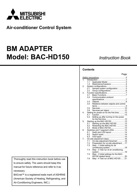
Air-conditioner Control System<br />
<strong>BM</strong> <strong>ADAPTER</strong><br />
<strong>Model</strong>: <strong>BAC</strong>-<strong>HD150</strong> Instruction Book<br />
Thoroughly read this instruction book before use<br />
to ensure safety. The users should keep this<br />
manual for future reference and refer to it as<br />
necessary.<br />
<strong>BAC</strong>net is a registered trade mark of ASHRAE<br />
(American Society of Heating, Refrigerating, and<br />
Air-Conditioning Engineers, INC.).<br />
Contents<br />
Page<br />
Safety precautions .................................................2<br />
1. Introduction....................................................3<br />
1.1 Applicable <strong>Model</strong> .................................3<br />
1.2 Restrictions/Cautions...........................4<br />
2. System configurations...................................5<br />
2.1 Sample system configuration...............5<br />
2.2 Group configurations ...........................6<br />
3. Function specifications..................................7<br />
3.1 Basic Functions ...................................7<br />
3.2 Communication protocol<br />
specifications .......................................7<br />
3.3 Objects.................................................8<br />
3.4 Relations between objects and control<br />
items ....................................................9<br />
3.5 Services.............................................10<br />
3.6 Services per object ............................12<br />
4. Setting for power-on for the first time ..........13<br />
4.1 Caution ..............................................13<br />
4.2 Setting up after turning on the power<br />
for the first time..................................13<br />
5. Starting up the <strong>BAC</strong>-<strong>HD150</strong> ........................13<br />
5.1 Starting up the <strong>BAC</strong>-<strong>HD150</strong>...............13<br />
5.2 Restarting the <strong>BAC</strong>-<strong>HD150</strong>................13<br />
5.3 Mode of <strong>BAC</strong>-<strong>HD150</strong> .........................13<br />
6. Switches and 7-segment LEDs ...................14<br />
6.1 Swith and LED layout ........................14<br />
6.2 Switch types.......................................14<br />
6.3 LED types ..........................................15<br />
7. On-site adjustment steps.............................16<br />
7.1 On-site adjustment flowchart .............16<br />
7.2 Preparation for on-site adjustment.....17<br />
7.3 Step - 1 Initial setting for air<br />
conditioning system ...........................18<br />
7.4 Step - 2 Test run of air conditioning<br />
system ...............................................19<br />
7.5 Step - 3 Initial settings for the <strong>BAC</strong>-<br />
<strong>HD150</strong> related items ..........................20<br />
7.6 Step - 4 Test run of <strong>BAC</strong>-<strong>HD150</strong> .......21
Safety precautions<br />
Before using the <strong>BAC</strong>-<strong>HD150</strong>, read the Safety Precautions section carefully to ensure proper operation.<br />
These safety precautions must be observed by anyone who operates the <strong>BAC</strong>-<strong>HD150</strong>.<br />
Keep the Instruction Book and Installation Manual for future reference. Make sure both manuals are passed on to any<br />
future air condition system users.<br />
WARNING<br />
CAUTION<br />
This symbol indicates that failure to follow the instructions exactly as stated poses the risk<br />
of serious injury of death.<br />
This symbol indicates that failure to follow the instructions exactly as stated poses the risk<br />
of injury or damage to the <strong>BAC</strong>-<strong>HD150</strong>.<br />
The unit must be installed by a dealer or technical<br />
representative.<br />
Improper installation by an unqualified person may result<br />
in electric shock and fire.<br />
Install in a location that is strong enough to<br />
withstand the weight of the unit.<br />
A weak installation area may cause the unit to fall down,<br />
resulting in a personal injury.<br />
Only use specified cables. Securely connect each<br />
cable so that the weight of the cable is not applied to<br />
the connectors.<br />
Loose or improper connections may result in heat<br />
generation or fire.<br />
If any abnormality is noticed (e.g., burning smell), stop<br />
the operation, turn off the power supply, and contact<br />
your dealer or technical representative immediately.<br />
Continuing the operation may result in damage to the<br />
<strong>BAC</strong>-<strong>HD150</strong>, electric shock, or fire.<br />
Do not install the <strong>BAC</strong>-<strong>HD150</strong> where there is a risk of<br />
leaking flammable gas.<br />
If the leaked gas accumulates around the <strong>BAC</strong>-<strong>HD150</strong>, it<br />
may ignite and cause an explosion.<br />
Do not wash the <strong>BAC</strong>-<strong>HD150</strong> with water.<br />
Doing so may cause an electric shock or malfunction.<br />
Do not use the <strong>BAC</strong>-<strong>HD150</strong> for specialized<br />
applications.<br />
This product is designed exclusively for use with the<br />
MITSUBISHI ELECTRIC building air conditioning control<br />
system. The use of this product for other purposes may<br />
result in malfunctions.<br />
Do not spray insect sprays or sprays with flammable<br />
propellants to the <strong>BAC</strong>-<strong>HD150</strong>.<br />
To avoid the risk of fire or explosion, do not place<br />
flammable sprays near the <strong>BAC</strong>-<strong>HD150</strong> or spray them<br />
directly on the <strong>BAC</strong>-<strong>HD150</strong>.<br />
Do not apply mechanical shock to <strong>BAC</strong>-HD 150.<br />
WARNING<br />
CAUTION<br />
- 2 -<br />
Ask your dealer or an authorized technician to move<br />
or reinstall the <strong>BAC</strong>-<strong>HD150</strong>.<br />
Improper installation may result in an electric shock or<br />
fire.<br />
<strong>BAC</strong>-<strong>HD150</strong> must be disposed of properly.<br />
Contact your dealer for proper disposal procedures.<br />
Do not attempt to modify or repair the <strong>BAC</strong>-<strong>HD150</strong>.<br />
Modification or improper repair may result in electric<br />
shock or fire. Consult your dealer when repairs are<br />
necessary.<br />
Stop the operation immediately and notify your<br />
dealer if the <strong>BAC</strong>-<strong>HD150</strong> does not operate, or when<br />
any abnormality is noticed.<br />
Continuing the operation may result in damage to the<br />
<strong>BAC</strong>-<strong>HD150</strong> or fire.<br />
Do not use the <strong>BAC</strong>-<strong>HD150</strong> in an environment high in<br />
oil, steam, or sulfuric gas.<br />
These substances may have adverse effects on the<br />
performance of the <strong>BAC</strong>-<strong>HD150</strong> or damage its parts.<br />
Operate the <strong>BAC</strong>-<strong>HD150</strong> within the temperature range<br />
specification.<br />
The use of controller outside of its specification may<br />
result in serious damage to the <strong>BAC</strong>-<strong>HD150</strong>. Be sure to<br />
check the temperature range specification in the<br />
Installation Manual.<br />
Use a security device such as a VPN router when<br />
connecting the <strong>BAC</strong>-<strong>HD150</strong> to the Internet to prevent<br />
unauthorized access.<br />
If no security devices are installed, the operation settings<br />
may be changed by an unauthorized person without the<br />
knowledge of the user.
1 Introduction<br />
1.1 Applicable <strong>Model</strong><br />
<strong>BAC</strong>-<strong>HD150</strong> have functions to monitor and operate air conditioning units (excl. certain models).<br />
CITY MULTI<br />
LOSSNAY<br />
OA Processing unit<br />
: Supported<br />
X : Not supported<br />
Table: <strong>Model</strong>s and available functions<br />
<strong>Model</strong> Function (Monitor/Operation)<br />
S series<br />
Y Series<br />
R2 series<br />
WY series<br />
WR2 series<br />
A-control unit (Mr Slim)<br />
(Requires an adapter)<br />
AK-control unit (Mr Slim) x<br />
K-control unit x<br />
Room air conditioner (RAC) x<br />
Air To Water Booster unit/Air To Water<br />
HEX unit<br />
x<br />
- 3 -
1.2 Restrictions/Cautions<br />
Restrictions and Cautions for <strong>BAC</strong>-<strong>HD150</strong> are as follows.<br />
(1) Restrictions on the system configuration<br />
Number of connectable units Notes<br />
M-NET One line only<br />
Indoor unit 50 units max./M-NET Includes all IC, AIC, LC, FU.<br />
Symbol IC: Indoor unit; AIC: A control indoor unit;<br />
LC: LOSSNAY; FU: OA Processing unit<br />
(2) Supports for errors<br />
• It is recommended to recover the system immediately when errors related to air conditioning are displayed on the building<br />
management system.<br />
(3) Operation during power failure<br />
• When <strong>BAC</strong>-<strong>HD150</strong> needs to be operated during power failure, a power backup device such as UPS (Uninterruptible Power<br />
Supply) is recommended to be installed.<br />
(4) Functions<br />
• Due to continuing improvement, specifications are subject to change without notice.<br />
- 4 -
2 System configurations<br />
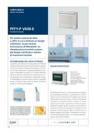
2.1 Sample system configuration<br />
HUB<br />
<strong>BAC</strong>net<br />
<strong>BAC</strong>-<strong>HD150</strong><br />
System remote controller<br />
M-NET<br />
<strong>BAC</strong>net<br />
��<br />
�<br />
�<br />
�<br />
�<br />
Outdoor unit<br />
Outdoor unit<br />
ME remote controller<br />
ME remote controller<br />
M-NET: <strong>Mitsubishi</strong> Electric air conditioning control line<br />
- 5 -<br />
Building Management System<br />
HUB<br />
M-NET<br />
M-NET<br />
HUB: Switching HUB<br />
Indoor unit LOSSNAY<br />
Indoor unit LOSSNAY
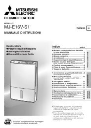
2.2 Group configurations<br />
<strong>BAC</strong>net controls each group.<br />
<strong>BAC</strong>net contol hierarchy consists of M-NET number + Group number + Member number.<br />
Refer to “3.4 Relations between objects and control items” for member number details.<br />
(1) M-NET number<br />
Fixed to 01<br />
(2) Group number<br />
Multiple indoor units (IC) can be controlled as a target group. Group number range: 1-50<br />
(3) Member number<br />
Corresponds to Monitor/Operation items of air conditioners<br />
�<br />
�<br />
�<br />
�<br />
�<br />
�<br />
�<br />
�<br />
�<br />
�<br />
�<br />
�<br />
�<br />
�<br />
�<br />
�<br />
�<br />
�<br />
<strong>BAC</strong>net<br />
<strong>BAC</strong>-<strong>HD150</strong> �<br />
M-NET<br />
Building Management System<br />
Air conditioning system<br />
IC IC IC IC<br />
01 02<br />
�<br />
Group<br />
03 04<br />
�<br />
Group<br />
No.01 No.03<br />
- 6 -<br />
IC<br />
05<br />
Unit address<br />
Group number<br />
Outdoor units, remote<br />
controllers, and etc. are omitted<br />
in this drawing.
3 Function specifications<br />
3.1 Basic Functions<br />
<strong>BAC</strong>-<strong>HD150</strong> has functions that communication from an air conditioning system is protocol converted to <strong>BAC</strong>net<br />
communication, that command from a Building Management System is converted and transmitted to an air conditioning<br />
system, and that air conditioning system status data is collected and the status change is detected. <strong>BAC</strong>-<strong>HD150</strong> also collects<br />
data on air conditioning units operation status and transmits the data upon request from the building management system.<br />
Refer to “3.4 Relations between objects and control items” for control item of <strong>BAC</strong>-<strong>HD150</strong>.<br />
3.2 Communication protocol specifications<br />
(1) General descriptions of protocol<br />
<strong>BAC</strong>net/IP which applied to ANSI/ASHRAE 135-2004 correspondingly on UDP/IP of Ethernet is used.<br />
Ethernet header IP header UDP header BVLL header NPCI APDU<br />
Ethernet is a registered trademark of Fuji Xerox, Inc.<br />
(2) Ethernet header<br />
Physical layer: Ethernet<br />
Transmission medium: 10BASE-T<br />
(3) IP header<br />
Class C private address is recommended. (*1) Subnet Mask: 255.255.255.0<br />
*1: Recommended value (range): [192.168.1.1] - [192.168.254.254]<br />
Do not use [192.168.0.0] and [192.168.255.255] as a device address.<br />
(4) UDP header<br />
The default UDP port of unicast and broadcasting is set to 47808 (0x<strong>BAC</strong>0).<br />
(5) BVLL header (BVLL: <strong>BAC</strong>net Virtual Link Layer)<br />
BVLC type (1 octet) Fixed to 0x81 (BVLL against <strong>BAC</strong>net/IP)<br />
BVLC function (1 octet) Unicast 0x0A<br />
Broadcast 0x0B<br />
BVLC length (2 octets) Variable (BVLL header (4 octets) + NPCI data length + APDU data length)<br />
(Typical examples are listed above. Refer to ANSI/ASHRAE 135-2004 for details.)<br />
(6) NPCI (NPCI: Network Layer Protocol Control Information)<br />
Version (1 octet) Fixed to 0x01<br />
Control (1 octet) Response is received. 0x04<br />
No response 0x00<br />
(Typical examples are listed above. Refer to ANSI/ASHRAE 135-2004 for details.)<br />
(7) APDU (APDU: Application Layer Protocol Data Unit)<br />
Data: 1024 octets or less<br />
(Refer to ANSI/ASHRAE 135-2004 for details.)<br />
- 7 -
3.3 Objects<br />
Supported object list is shown below.<br />
Object type Abbreviation Support Control item Notes<br />
Accumulator 23 − −<br />
Analog Input 0 AI Room Temp<br />
Analog Output 1 − −<br />
Analog Value 2 AV Set Temp<br />
Averaging 18 − −<br />
Binary Input 3 BI<br />
On Off State<br />
Alarm Signal<br />
Filter Sign<br />
Communication State<br />
Binary Output 4 BO On Off Setup<br />
Filter Sign Reset<br />
Prohibition On Off<br />
Binary Value 5 BV<br />
Prohibition Mode<br />
Prohibition Filter Sign Reset<br />
Prohibition Set Temperature<br />
System Forced Off<br />
Calendar 6 − −<br />
Command 7 − −<br />
Device 8 DEV Device object of <strong>BAC</strong>-<strong>HD150</strong><br />
Event Enrollment 9 − −<br />
File 10 − −<br />
Group 11 − −<br />
Life Safety Point 21 − −<br />
Life Safety Zone 22 − −<br />
Loop 12 − −<br />
Multi-state Input 13 MI<br />
Multi-state Output 14 MO<br />
Multi-state Value 19 − −<br />
Notification Class 15 CLS −<br />
Program 16 − −<br />
Pulse Converter 24 − −<br />
Schedule 17 − −<br />
Trend Log 20 − −<br />
: Supported<br />
− : Not supported<br />
- 8 -<br />
Error Code<br />
Operational Mode State<br />
Fan Speed State<br />
Air Direction State<br />
Ventilation Mode State<br />
Operational Mode Setup<br />
Fan Speed Setup<br />
Air Direction Setup<br />
Ventilation Mode Setup
3.4 Relations between objects and control items<br />
Object ID consists of object type + instance number.<br />
Instance number consists of M-NET number, air conditioner group number, and member number.<br />
31 22 21 0<br />
<strong>BAC</strong>net object type Instance number<br />
<strong>BAC</strong>net object type : Refer to the object type as shown in the table below.<br />
Instance number (6 digits in decimal notation) : 01 xx xx<br />
Object<br />
type<br />
Instance<br />
number<br />
Control item<br />
Inactive Active<br />
Text-1 Text-2 Text-3 Text-4 Text-5<br />
On Off Setup BO 01xx01 Stop Run<br />
On Off State BI 01xx02 Stop Run<br />
Alarm Signal BI 01xx03 Normal Error<br />
01: Normal 06: Electronic<br />
02: Other errors system error<br />
Error Code MI 01xx04 Normal<br />
03: Refrigeration<br />
system fault<br />
07: Sensor fault<br />
08: Communication<br />
04: Water system error error<br />
05: Air system error 09: System error<br />
Operational Mode Setup MO 01xx05 Cooling Heating Fan Auto Dry *1) *4)<br />
Operational Mode State MI 01xx06 Cooling Heating Fan Auto Dry<br />
*1)<br />
Fan Speed Setup MO 01xx07 Low High Mid 2 Mid 1<br />
*2) *4)<br />
Fan Speed State MI 01xx08 Low High Mid 2 Mid 1<br />
*2)<br />
Room Temp AI 01xx09 °F/°C *3)<br />
Set Temp AV 01xx10 °F/°C *3) *5)<br />
Filter Sign BI 01xx11 OFF ON<br />
Filter Sign Reset BV 01xx12 Reset Void<br />
Prohibition On Off BV 01xx13 Permit Prohibit<br />
Prohibition Mode BV 01xx14 Permit Prohibit<br />
Prohibition Filter Sign Reset BV 01xx15 Permit Prohibit<br />
Prohibition Set Temperature BV 01xx16 Permit Prohibit<br />
Communication State BI 01xx20 Normal Error<br />
System Forced Off BV<br />
01xx21<br />
019921<br />
Reset Execute<br />
Air Direction Setup MO 01xx22 Horizontal Downblow<br />
60%<br />
Air Direction State MI 01xx23 Horizontal Downblow<br />
60%<br />
Ventilation Mode State MO 01xx35<br />
Heat<br />
exchange<br />
Ventilation Mode Setup MI 01xx36<br />
Heat<br />
exchange<br />
*1 : “Dry” can be used only when “use” is selected for the “Dry” setting. (“Dry” is not used for a default.)<br />
Fan is used for a group whose attribute is LC.<br />
*2 : “Mid 1/Mid 2” can be used only when “use” is selected for the “Mid 1/Mid 2” setting.<br />
(“Mid 1/Mid 2” is not used for a default.)<br />
Low< Mid 2< Mid 1< High<br />
*3 : Initial value is returned for a group whose attribute is LC because the group is not a target item.<br />
*4 : Different operation mode settings, fan speed settings, and airflow direction settings are available on different models.<br />
*5 : Settable indoor preset temperature range varies in each operation mode.<br />
• Cooling : 19-30 °C<br />
• Heating : 17-28 °C<br />
• Auto : 19-28 °C<br />
• Dry : 19-30 °C<br />
The settable range also varies with the models.<br />
- 9 -<br />
Member number (01-99)<br />
Group number (01-50, 99)<br />
M-NET number (fixed to 01)<br />
Unit<br />
Downblow<br />
80%<br />
Downblow<br />
80%<br />
Bypass Auto<br />
Bypass Auto<br />
Downblow<br />
100%<br />
Downblow<br />
100%<br />
Swing<br />
Swing<br />
*3)<br />
*3)<br />
Notes<br />
*3) *4)<br />
*3)
3.5 Services<br />
The following table shows the supported services.<br />
Service Initiate request Execute request<br />
1. Alarm and Event Services<br />
(1) Acknowlege Alarm Service − −<br />
(2) Confirmed COV Notification Service − −<br />
(3) Confirmed Event Notification Service − −<br />
(4) Get Alarm Summary Service − −<br />
(5) Get Enrollment Summary service − −<br />
(6) Get Event Information Service − −<br />
(7) Life Safety Operation Service − −<br />
(8) Subscribe COV Service − −<br />
(9) Subscribe COV Property Service − −<br />
2. File Access Services<br />
(1) Atomic Read File Service − −<br />
(2) Atomic Write File Service − −<br />
3. Object Access Services<br />
(1) Add List Element Service − −<br />
(2) Remove List Element Service − −<br />
(3) Create Object Service − −<br />
(4) Delete Object Service − −<br />
(5) Read Property Service −<br />
(6) Read Property Conditional Service − −<br />
(7) Read Property Multiple Service −<br />
(8) Read Range Service − −<br />
(9) Write Property Service −<br />
(10) Write Property Multiple Service −<br />
4. Remote Device Management Services<br />
(1) Device Communication Control Service − −<br />
(2) Confirmed Private Transfer Service − −<br />
(3) Confirmed Text Message Service − −<br />
(4) Reinitialize Device Service − −<br />
5. Virtual Terminal Services<br />
(1) VT-Open Service − −<br />
(2) VT-Close Service − −<br />
(3) VT-Data Service6.Security Services − −<br />
: Supported<br />
− : Not supported<br />
Initiate request: Provides services<br />
Execute request: Receives and uses services<br />
- 10 -
Service Initiate request Execute request<br />
6. Security Services<br />
(1) Authenticate Service − −<br />
(2) Request Key Service − −<br />
7.Unconfirmed Services<br />
(1)I-Am −<br />
(2)I-Have −<br />
(3)Unconfirmed COV Notification Service − −<br />
(4)Unconfirmed Event Notification Service − −<br />
(5)Unconfirmed Private Transfer Service − −<br />
(6)Unconfirmed Text Message Service − −<br />
(7)Time Synchronization Service −<br />
(8)UTC Time Synchronization Service − −<br />
(9)Who-Has −<br />
(10)Who-Is −<br />
: Supported<br />
− : Not supported<br />
Initiate request: Provides services<br />
Execute request: Receives and uses services<br />
- 11 -
3.6 Services per object<br />
The following table shows the supported service per object.<br />
Object<br />
Service Device<br />
Read Property<br />
Read Property Multiple<br />
Write Property<br />
Write Property Multiple<br />
I-Am<br />
I-Have<br />
Time Synchronization<br />
Who-Has<br />
Who-Is<br />
INIT: Provides services<br />
EXEC: Receives and uses services<br />
: Supported<br />
: Changeable using setting data<br />
INIT<br />
EXEC<br />
INIT<br />
EXEC<br />
INIT<br />
EXEC<br />
INIT<br />
EXEC<br />
INIT<br />
EXEC<br />
INIT<br />
EXEC<br />
INIT<br />
EXEC<br />
INIT<br />
EXEC<br />
INIT<br />
EXEC<br />
Analog<br />
Input<br />
Analog<br />
Value<br />
- 12 -<br />
Binary<br />
Input<br />
Binary<br />
Output<br />
Binary<br />
Value<br />
Multi-State<br />
Input<br />
Multi-State<br />
Output<br />
Notes
4 Setting for power-on for the first time<br />
4.1 Caution<br />
<strong>BAC</strong>net LAN IP address for <strong>BAC</strong>-<strong>HD150</strong> is set to “192.168.1.254” at factory setting.<br />
The address may overlap one of the addresses that are assigned to other devices connected to <strong>BAC</strong>net. When turning on the<br />
power for the first time after installation, turn on the power with the <strong>BAC</strong>net LAN cable with <strong>BAC</strong>-<strong>HD150</strong> disconnected.<br />
If an address overlaps any of the addresses that are assigned to other devices, <strong>BAC</strong>net communication cannot be performed<br />
properly via <strong>BAC</strong>-<strong>HD150</strong> or other devices.<br />
Connect the LAN cable for <strong>BAC</strong>-<strong>HD150</strong> to <strong>BAC</strong>net after IP address is set by using <strong>BAC</strong>-<strong>HD150</strong> Setting Tool (abbreviated to<br />
Setting Tool below).<br />
4.2 Setting up after turning on the power for the first time<br />
Make initial setting using Setting Tool after the power to <strong>BAC</strong>-<strong>HD150</strong> is turned on.<br />
Refer to the Instruction Book that came with Setting Tool for details about Initial Setting.<br />
5 Starting up the <strong>BAC</strong>-<strong>HD150</strong><br />
5.1 Starting up the <strong>BAC</strong>-<strong>HD150</strong><br />
<strong>BAC</strong>-<strong>HD150</strong> starts up when the power is turned on.<br />
<strong>BAC</strong>net communication and M-NET communication are performed after startup.<br />
5.2 Restarting the <strong>BAC</strong>-<strong>HD150</strong><br />
<strong>BAC</strong>-<strong>HD150</strong> restarts when SW403 is pressed.<br />
5.3 Mode of <strong>BAC</strong>-<strong>HD150</strong><br />
<strong>BAC</strong>-<strong>HD150</strong> has “Online” mode and “Offline” mode.<br />
“Online” mode is an operation mode to perform <strong>BAC</strong>net communication and M-NET communication.<br />
“Offline” mode is a maintenance mode in which <strong>BAC</strong>net communication and M-NET communication are not performed.<br />
It is the mode in which the Setting Tool can configure data settings to the <strong>BAC</strong>-<strong>HD150</strong>.<br />
Mode change between “Online” and “Offline” are as follows.<br />
• Startup by turning on<br />
the power<br />
• Restart by resetting<br />
• Receiving “Change to Online mode request ”<br />
from the Setting Tool.<br />
- 13 -<br />
Online mode<br />
Offline mode<br />
• Receiving “Change to Offline mode request ”<br />
from the Setting Tool.<br />
• “Change to Offline mode” by operating the<br />
switch.
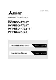
6 Switches and 7-segment LEDs<br />
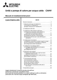
6.1 Swith and LED layout<br />
The layouts of the switches and LEDs on <strong>BAC</strong>-<strong>HD150</strong> are shown below.<br />
TB3<br />
Switch Board<br />
M-NET Board<br />
6.2 Switch types<br />
(1) Dipswitches<br />
SW601, SW602, SW603, and SW604 are available.<br />
(The above switches are for future use.)<br />
(2) Rotary switches<br />
SW606 and SW607 are available.<br />
(The above switches are for future use.)<br />
Main Board<br />
(3) Push switches<br />
SW403 and SW605 are available.<br />
(SW403 is used to restart <strong>BAC</strong>-<strong>HD150</strong>, and SW605 is for future use.)<br />
TB1<br />
Error LED<br />
SW403<br />
- 14 -<br />
7-segment LED<br />
SW601<br />
SW605<br />
SW606,SW607<br />
SW604<br />
SW603<br />
SW602
6.3 LED types<br />
(1) 7-segment LEDs<br />
Each set of two vertically aligned lines in the 7-segment LEDs display the information that is summarized in the table below.<br />
LD1 CPU status<br />
Lit : Normal<br />
Unlit : Error<br />
LD2 (Undefined) −<br />
LD3 <strong>BAC</strong>net communication status<br />
LD4 Air conditioning unit errors<br />
(2) Error LED<br />
The Error LED lights up when there is a <strong>BAC</strong>net communication error. It remains turned off when no errors are occurring.<br />
- 15 -<br />
Lit : Error<br />
Unlit : Normal<br />
Lit : At least one indoor unit is in error.<br />
Unlit : All indoor units are normal.<br />
Lit : Initial setting has not been completed.<br />
LD5 M-NET startup status<br />
Unlit : Initial setting has been completed.<br />
Blink: Initial setting in progress<br />
LD6 (Undefined) −<br />
LD7 <strong>BAC</strong>netIF mode<br />
LD8 <strong>BAC</strong>net communication service status<br />
7segment LED<br />
LD1<br />
Lit : Offline mode<br />
Unlit : Online mode<br />
LD2 LD3 LD4 LD5 LD6 LD7 LD8<br />
Lit : Communication lock (setting other than Enable)<br />
Unlit : Communication allowed (Enable)
7 On-site adjustment steps<br />
7.1 On-site adjustment flowchart<br />
Generally, on-site adjustment is divided into four steps as follows. By following these steps, the cause of trouble can be solved<br />
clearly and on-site adjustment can be identified efficiently.<br />
It is recommended to follow the steps below.<br />
Step - 1 Initial setting for air conditioning system<br />
Make the setting for the <strong>BAC</strong>-<strong>HD150</strong> system and air conditioning system group by using<br />
Setting Tool.<br />
Refer to the Instruction Book that came with the Setting Tool for <strong>BAC</strong>-<strong>HD150</strong> system setting<br />
and group setting for air conditioning system.<br />
Step - 2 Test run of air conditioning system<br />
Check that air conditioning units and controllers are system configured correctly and<br />
operate properly. (Refer to the Installation Manual that came with each device for how to<br />
perform test run.)<br />
Step - 3 Initial settings for <strong>BAC</strong>-<strong>HD150</strong> related items<br />
Make the setting for the <strong>BAC</strong>-<strong>HD150</strong> related items by using Setting Tool.<br />
Refer to the Instruction Book that came with Setting Tool for setting related to <strong>BAC</strong>net.<br />
Step - 4 Test run of <strong>BAC</strong>-<strong>HD150</strong><br />
Check that operation status of air conditioning units appears correctly on the <strong>BM</strong>S and that<br />
air conditioning units operate properly from the <strong>BM</strong>S control.<br />
<strong>BM</strong>S: Building Management System<br />
- 16 -
Step-1<br />
Step-3<br />
7.2 Preparation for on-site adjustment<br />
Have the following tools and documents ready before performing on-site adjustment and a test run.<br />
Reference<br />
Item Description Notes<br />
Tools and parts<br />
HUB<br />
<strong>BAC</strong>-<strong>HD150</strong><br />
System remote controller<br />
<strong>BAC</strong>net<br />
�<br />
M-NET<br />
�<br />
�<br />
Outdoor � unit<br />
�<br />
ME remote controller<br />
Outdoor unit<br />
ME remote controller<br />
Group configuration, IP address, Control item, and<br />
Air conditioning control system diagram<br />
etc.<br />
Instruction Book that came with <strong>BAC</strong>-<strong>HD150</strong> (This document)<br />
Instruction Book that came with Setting Tool<br />
<strong>BAC</strong>-<strong>HD150</strong> Installation Manual<br />
Relevant air-conditioner and controller’s<br />
Instructions Books and Installation Manuals<br />
Miscellaneous <strong>BAC</strong>net device list<br />
Computer For Setting Tool<br />
USB memory For setting data backup<br />
Installation CD for the Setting Tool Setup disk<br />
HUB For connection to Setting Tool<br />
LAN cable (straight cable)<br />
General tools such as a driver<br />
For connection to Setting Tool<br />
Tester<br />
Miscellaneous<br />
Use to check wiring and voltage.<br />
- 17 -<br />
Building Management System<br />
HUB<br />
M-NET<br />
M-NET<br />
Indoor unit LOSSNAY<br />
Indoor unit LOSSNAY<br />
Step-2<br />
Step-4
7.3 Step - 1 Initial setting for air conditioning system<br />
Make the initial settings for air conditioning system using Setting Tool.<br />
�<br />
Setting tool<br />
Step-1<br />
Change LAN<br />
connection<br />
HUB<br />
HUB<br />
<strong>BAC</strong>-<strong>HD150</strong><br />
System remote controller<br />
<strong>BAC</strong>net<br />
�<br />
M-NET<br />
�<br />
�<br />
Outdoor<br />
�<br />
unit<br />
�<br />
ME remote controller<br />
Outdoor unit<br />
ME remote controller<br />
(1) Installing the Setting Tool software<br />
Install the Setting Tool program on a PC, and set the IP address. (Refer to the Instruction Book that came with Setting Tool for<br />
installation and setting method.)<br />
(2) Connecting the Setting Tool<br />
To connect Setting Tool to <strong>BAC</strong>-<strong>HD150</strong>, disconnect LAN cable connecting to <strong>BAC</strong>net of <strong>BAC</strong>-<strong>HD150</strong>.<br />
Use additional HUB to connect <strong>BAC</strong>-<strong>HD150</strong> and Setting Tool.<br />
To connect <strong>BAC</strong>-<strong>HD150</strong> and the additional HUB, use LAN port (LAN1) connecting to <strong>BAC</strong>net.<br />
(3) Data setting<br />
Make the settings for the air conditioning system related items and IP address of <strong>BAC</strong>-<strong>HD150</strong> by using Setting Tool.<br />
The following table shows setting items. (Refer to the Instruction Book that came with Setting Tool for setting method.)<br />
No. Main tab Sub tab Setting item<br />
1<br />
2<br />
System Settings<br />
Basic System<br />
M-NET<br />
All setting items<br />
All setting items<br />
3<br />
4<br />
Group Settings<br />
Group<br />
LOSSNAY<br />
All setting items<br />
All setting items<br />
CAUTION<br />
When IP address is duplicated, not only <strong>BAC</strong>-<strong>HD150</strong> but also other equipments may malfunction in <strong>BAC</strong>net communication.<br />
Check IP address of <strong>BAC</strong>-<strong>HD150</strong> before setting.<br />
<strong>BAC</strong>-<strong>HD150</strong> and <strong>BAC</strong>net do not get connected in Step - 1 to 3, so the setting related to IP address in Step - 1 is not<br />
necessary. IP address is set in Step - 1 just for the case they are connected accidentally.<br />
- 18 -<br />
Building Management System<br />
HUB<br />
M-NET<br />
M-NET<br />
Indoor unit LOSSNAY<br />
Indoor unit LOSSNAY
7.4 Step - 2 Test run of air conditioning system<br />
Perform test run only on air conditioning system.<br />
�<br />
Setting tool<br />
HUB<br />
HUB<br />
<strong>BAC</strong>-<strong>HD150</strong><br />
System remote controller<br />
M-NET<br />
<strong>BAC</strong>net<br />
Outdoor unit<br />
Outdoor unit<br />
(1) Checking items before test run<br />
Check that test run of air conditioning units is completed.<br />
ME remote controller<br />
ME remote controller<br />
(2) Turning on the power of all the air conditioning units and system controllers<br />
Turn on the power of all the air conditioning units and system controllers.<br />
(3) Restarting the <strong>BAC</strong>-<strong>HD150</strong><br />
Restarting the <strong>BAC</strong>-<strong>HD150</strong>, then it becomes [Online mode].<br />
The setting data made in Step - 1 such as air conditioning system group is automatically sent from <strong>BAC</strong>-<strong>HD150</strong> to air<br />
conditioning system.<br />
(It may take about 5 minutes for the setting.)<br />
(4) Test run using system controller or remote controller<br />
Perform test run using system controller or remote controller to check operation status of each unit.<br />
* Refer to the Installation Manual that came with air conditioning unit and system controller for how to perform test run.<br />
- 19 -<br />
Building Management System<br />
HUB<br />
M-NET<br />
M-NET<br />
Indoor unit LOSSNAY<br />
Indoor unit LOSSNAY<br />
Step-2
7.5 Step - 3 Initial settings for the <strong>BAC</strong>-<strong>HD150</strong> related items<br />
Make the initial settings for <strong>BAC</strong>net using Setting Tool.<br />
�<br />
Setting tool<br />
Step-3<br />
HUB<br />
HUB<br />
<strong>BAC</strong>-<strong>HD150</strong><br />
System remote controller<br />
<strong>BAC</strong>net<br />
�<br />
M-NET<br />
�<br />
�<br />
Outdoor � unit<br />
�<br />
ME remote controller<br />
Outdoor unit<br />
ME remote controller<br />
(1) Data setting<br />
Make the settings for <strong>BAC</strong>net using Setting Tool.<br />
The following table shows setting items. (Refer to the Instruction Book that came with Setting Tool for setting method.)<br />
No. Main tab Sub tab Setting item<br />
1<br />
<strong>BAC</strong>net All setting items<br />
2<br />
3<br />
<strong>BAC</strong>net Settings<br />
Network and Device<br />
Object<br />
All setting items<br />
All setting items<br />
4 Other All setting items<br />
- 20 -<br />
Building Management System<br />
HUB<br />
M-NET<br />
M-NET<br />
Indoor unit LOSSNAY<br />
Indoor unit LOSSNAY
7.6 Step - 4 Test run of <strong>BAC</strong>-<strong>HD150</strong><br />
Connect <strong>BM</strong>S and perform test run of air conditioning system.<br />
�<br />
Setting tool<br />
Step-4<br />
Change LAN<br />
connection<br />
HUB<br />
HUB<br />
<strong>BAC</strong>-<strong>HD150</strong><br />
System remote controller<br />
<strong>BAC</strong>net<br />
(1) <strong>BAC</strong>net connection<br />
Switch LAN connection of <strong>BAC</strong>-<strong>HD150</strong> from Setting Tool to <strong>BAC</strong>net.<br />
(2) Restarting the <strong>BAC</strong>-<strong>HD150</strong><br />
Restart <strong>BAC</strong>-<strong>HD150</strong>, then it becomes [Online mode].<br />
(3) Test run items and method<br />
Refer to the next page for test run items and method.<br />
�<br />
M-NET<br />
�<br />
�<br />
Outdoor � unit<br />
�<br />
ME remote controller<br />
Outdoor unit<br />
ME remote controller<br />
- 21 -<br />
Building Management System<br />
HUB<br />
M-NET<br />
M-NET<br />
Indoor unit LOSSNAY<br />
Indoor unit LOSSNAY
On-site adjustment sheet for <strong>BAC</strong>net interface (proposal)<br />
Check these items to use the system.<br />
Control item Object Status Steps<br />
Group No. [ ]<br />
Result<br />
On Off Setup BO_01xx01<br />
On Off State BI_01xx02<br />
Alarm Signal BI_01xx03<br />
Error Code MI_01xx04<br />
Operational Mode<br />
Setup<br />
Operational Mode<br />
State<br />
MO_01xx05<br />
MI_01xx06<br />
Fan Speed Setup MO_01xx07<br />
Fan Speed State MI_01xx08<br />
Room temp AI_01xx09 °C<br />
Set Temp AV_01xx10 °C<br />
Filter Sign BI_01xx11<br />
Filter Sign Reset BV_01xx12<br />
INACTIVE: Stop<br />
ACTIVE: Run<br />
INACTIVE: Stop<br />
ACTIVE: Run<br />
INACTIVE: Normal<br />
ACTIVE: Error<br />
01 : Normal<br />
02 : Other errors<br />
03 : Refrigeration fault<br />
04 : Water error<br />
05 : Air error<br />
06 : Electronic error<br />
07 : Sensor fault<br />
08 : Communication error<br />
09 : System error<br />
01 : Cooling<br />
02 : Heating<br />
03 : Fan<br />
04 : Auto<br />
05 : Dry (*4)<br />
01 : Cooling<br />
02 : Heating<br />
03 : Fan<br />
05 : Dry (*4)<br />
01 : Low<br />
02 : High<br />
03 : Mid 2 (*5)<br />
05 : Mid 1 (*5)<br />
01 : Low<br />
02 : High<br />
03 : Mid 2 (*5)<br />
04 : Mid 1 (*5)<br />
INACTIVE : OFF<br />
ACTIVE : ON<br />
INACTIVE : RESET<br />
ACTIVE : Void<br />
• Turn ON/OFF the specific group from <strong>BM</strong>S(*1).<br />
After doing so, check that the operation status of the group<br />
renews the condition using system controller or remote<br />
controller.<br />
• Turn ON/OFF the specific group using system controller<br />
or remote controller.<br />
After doing so, check that the operation status of the group<br />
renews the condition on <strong>BM</strong>S .<br />
• Make an error on an air conditioning units of the specific<br />
group.<br />
After doing so, check that the warning signal of the group<br />
turns to (ACTIVE) on <strong>BM</strong>S. (*2)<br />
• Recover the error of the air conditioning units of the<br />
specific group.<br />
After doing so, check that the warning signal of the group<br />
turns to (INACTIVE) on <strong>BM</strong>S.<br />
• Disconnect M-NET transmission line that is connected to<br />
<strong>BAC</strong>-<strong>HD150</strong>.<br />
After doing so, check that the error code of all groups turns<br />
to Communication error (08) on <strong>BM</strong>S. (*3)<br />
• Connect M-NET transmission line to <strong>BAC</strong>-<strong>HD150</strong>.<br />
After doing so, check that the error code of all groups turns<br />
to Normal (01) on <strong>BM</strong>S.<br />
(Do not perform this check when other errors occur.)<br />
• Change operation mode of the specific group from <strong>BM</strong>S.<br />
After doing so, check that the operation mode of the group<br />
renews the mode using system controller or remote<br />
controller.<br />
• Change operation mode of the specific group using<br />
system controller or remote controller.<br />
After doing so, check that the operation mode of the group<br />
renews the mode on <strong>BM</strong>S.<br />
• Change fan speed of the specific group from <strong>BM</strong>S.<br />
After doing so, check that the fun speed of the group<br />
renews the speed using system controller or remote<br />
controller.<br />
• Change fun speed of the specific group using system<br />
controller or remote controller.<br />
After doing so, check that the fun speed of the group<br />
renews the speed on <strong>BM</strong>S.<br />
• Change intake air temperature and check if the display of<br />
<strong>BM</strong>S and system controller/remote controller are the<br />
same.<br />
• Make a setting of set room temperature of the specific<br />
group from <strong>BM</strong>S.<br />
After doing so, check that the set room temperature of the<br />
group renews the temperature using system controller or<br />
remote controller.<br />
• Change the set room temperature of the specific group<br />
using system controller or remote controller.<br />
After doing so, check that the set room temperature of the<br />
group renews the temperature on <strong>BM</strong>S.<br />
• Perform something to turn on the filter sign. (*2)<br />
After doing so, check that the filter sign of the group turns to<br />
ON(ACTIVE) on <strong>BM</strong>S.<br />
• Reset the filter sign of the group that detects filter sign<br />
[ON(ACTIVE)] from <strong>BM</strong>S. (*2)<br />
After doing so, check that the filter sign of the group turns to<br />
OFF(INACTIVE) on <strong>BM</strong>S.<br />
- 22 -
Control item Object Status Steps Result<br />
Prohibition On Off BV_01xx13<br />
Prohibition Mode BV_01xx14<br />
Prohibition Filter<br />
Sign Reset<br />
Prohibition Set<br />
Temperature<br />
Communication<br />
State<br />
BV_01xx15<br />
BV_01xx16<br />
BI_01xx20<br />
System Forced Off BV_01xx21<br />
BV_019921<br />
Air Direction Setup MO_01xx22<br />
Air Direction State MI_01xx23<br />
Ventilation Mode<br />
Setup<br />
Ventilation Mode<br />
State<br />
MO_01xx35<br />
MI_01xx36<br />
INACTIVE : Permit<br />
ACTIVE : Prohibit<br />
INACTIVE : Permit<br />
ACTIVE : Prohibit<br />
INACTIVE : Permit<br />
ACTIVE : Prohibit<br />
INACTIVE : Permit<br />
ACTIVE : Prohibit<br />
INACTIVE: Normal<br />
ACTIVE: Error<br />
INACTIVE: Reset<br />
ACTIVE: Execute<br />
01 : Horizontal<br />
02 : Downblow 60%<br />
03 : Downblow 80%<br />
04 : Downblow 100%<br />
05 : Swing<br />
01 : Horizontal<br />
02 : Downblow 60%<br />
03 : Downblow 80%<br />
04 : Downblow 100%<br />
05 : Swing<br />
01 : Heat exchange<br />
02 : Bypass<br />
03 : Auto<br />
01 : Heat exchange<br />
02 : Bypass<br />
03 : Auto<br />
• Prohibit the remote controller (ON/OFF) of the specific<br />
group from <strong>BM</strong>S.<br />
After doing so, check that the remote controller (ON/OFF) of<br />
the group turns to (ACTIVE) via the remote controller.<br />
• Permit the remote controller (ON/OFF) of the specific<br />
group from <strong>BM</strong>S.<br />
After doing so, check that the remote controller (ON/OFF) of<br />
the group turns to (INACTIVE) via the remote controller.<br />
• Operation/checking object is the same as the steps of<br />
remote controller (operation mode), but the checking<br />
method is the same as the steps of remote controller (ON/<br />
OFF).<br />
• Operation/checking object is the same as the steps of<br />
remote controller (filter sign reset), but the checking<br />
method is the same as the steps of remote controller (ON/<br />
OFF).<br />
• Operation/checking object is the same as the steps of<br />
remote controller (set temperature), but the checking<br />
method is the same as the steps of remote controller (ON/<br />
OFF).<br />
• Disconnect M-NET transmission line which is connected<br />
to <strong>BAC</strong>-<strong>HD150</strong>.<br />
After doing so, check that the communication condition of all<br />
groups turns to error (ACTIVE) on <strong>BM</strong>S. (*3)<br />
• Connect M-NET transmission line to <strong>BAC</strong>-<strong>HD150</strong>.<br />
After doing so, check that the error code of all groups turns<br />
to Normal (INACTIVE) on <strong>BM</strong>S.<br />
• Perform a forced stop of the system of the specific group<br />
from <strong>BM</strong>S.<br />
After doing so, check that the air conditioner stops on <strong>BM</strong>S.<br />
• Change the air direction of the specific group from <strong>BM</strong>S.<br />
After doing so, check that the air direction of the group<br />
renews the direction using system controller or remote<br />
controller.<br />
• Change the air direction of the specific group using<br />
system controller or remote controller.<br />
After doing so, check that the air direction of the group<br />
renews the direction on <strong>BM</strong>S.<br />
• Change the LOSSNAY ventilation mode of the specific<br />
group from <strong>BM</strong>S.<br />
After doing so, check that the LOSSNAY ventilation mode of<br />
the group renews the mode using system controller or<br />
remote controller.<br />
• Change the LOSSNAY ventilation mode of the specific<br />
group using system controller or remote controller.<br />
After doing so, check that the LOSSNAY ventilation mode of<br />
the group renews the mode on <strong>BM</strong>S.<br />
*1: <strong>BM</strong>S = Building Management System<br />
*2: Consult a <strong>Mitsubishi</strong> personnel for the confirmation method.<br />
*3: It can take up to five minutes for an error to be detected.<br />
*4: “Dry” can be used only when “use” is selected for the “Dry” setting (“Dry” is not used for a default.)<br />
*5: “Mid 1/Mid 2” can be used only when “use” is selected for the “Mid 1/Mid 2” setting. (“Mid 1/Mid 2” is not used for a default.)<br />
- 23 -
This product is designed and intended for use in the residential,<br />
commercial and light-industrial environment.<br />
The product at hand is<br />
based on the following<br />
EU regulations:<br />
• Low Voltage Directive 2006/95/EC<br />
• Electromagnetic Compatibility Directive,<br />
2004/108/EC<br />
Please be sure to put the contact address/telephone number on<br />
this manual before handing it to the customer.<br />
HEAD OFFICE: TOKYO BLDG. , 2-7-3, MARUNOUCHI, CHIYODA-KU, TOKYO 100-8310, JAPAN<br />
Authorized representative in EU: MITSUBISHI ELECTRIC EUROPE B.V.<br />
HARMAN HOUSE, 1 GEORGE STREET, UXBRIDGE, MIDDLESEX UB8 1QQ, U.K.<br />
WT05542X01<br />
Printed in Japan<br />
Recycled Paper