11-7 Force Analysis of Spur Gears Gear Free Body Diagrams ...
11-7 Force Analysis of Spur Gears Gear Free Body Diagrams ...
11-7 Force Analysis of Spur Gears Gear Free Body Diagrams ...

You also want an ePaper? Increase the reach of your titles
YUMPU automatically turns print PDFs into web optimized ePapers that Google loves.
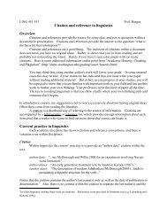
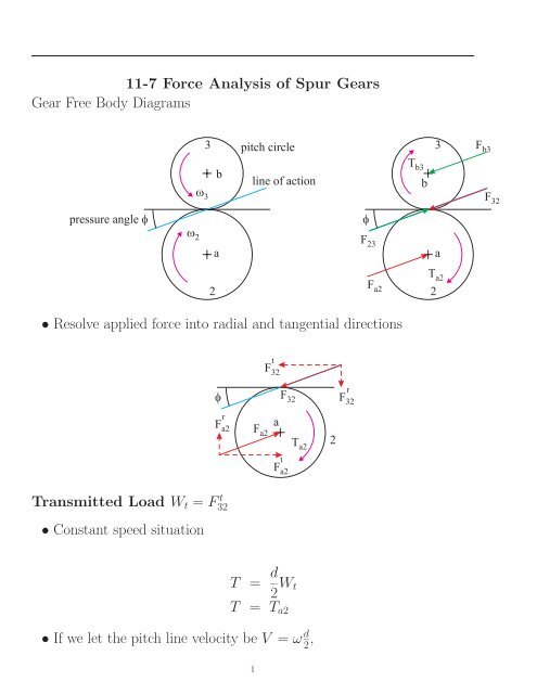
<strong>11</strong>-7 <strong>Force</strong> <strong>Analysis</strong> <strong>of</strong> <strong>Spur</strong> <strong><strong>Gear</strong>s</strong><br />
<strong>Gear</strong> <strong>Free</strong> <strong>Body</strong> <strong>Diagrams</strong><br />
pressure angle �<br />
� 2<br />
� 3<br />
3 pitch circle<br />
3<br />
b<br />
line <strong>of</strong> action<br />
a a<br />
2 2<br />
• Resolve applied force into radial and tangential directions<br />
r<br />
Fa2 Transmitted Load Wt = F t 32<br />
• Constant speed situation<br />
�<br />
F a2<br />
t<br />
F32 a<br />
F 32<br />
t<br />
Fa2 T = d<br />
2 Wt<br />
T = Ta2<br />
T a2<br />
• If we let the pitch line velocity be V = ω d<br />
2 ,<br />
1<br />
2<br />
r<br />
F32 �<br />
F 23<br />
F a2<br />
T b3<br />
b<br />
T a2<br />
F b3<br />
F 32
• In SI units:<br />
where<br />
Power = <strong>Force</strong> × Velocity<br />
Wt = (60)(1000)H<br />
πωd<br />
- Wt = tangential force in N or kN<br />
- H =powerinWorkW<br />
- ω = rotational speed in rpm<br />
- d = diameter in mm<br />
• Note that the formula above takes into account the unit conversions<br />
• In MathCAD, you can use<br />
Wt = 2H<br />
ωd<br />
in whatever units you select.<br />
• MathCAD will take care <strong>of</strong> units, as long as you specify units for all<br />
variables.<br />
• In US units:<br />
where<br />
H = WtV<br />
33000<br />
= Tω<br />
63000<br />
- Wt = tangential force in lbf<br />
- H = horsepower in HP<br />
- V = tangential speed in ft/min = πdω<br />
12<br />
- d = diameter in in<br />
2
- ω = rotational speed in rpm<br />
• We also have<br />
T = 63000H<br />
ω<br />
• The radial force acting on the gear is given by<br />
Wr = Wt tan φ<br />
• The total force acting on the gear is<br />
W = Wt<br />
cos φ<br />
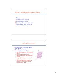
Example<br />
Shaft a has a power input <strong>of</strong> 75 kW at a speed <strong>of</strong> 1000 rpm counterclockwise.<br />
<strong><strong>Gear</strong>s</strong> have a module <strong>of</strong> 5 mm and a 20◦ pressure angle. <strong>Gear</strong><br />
3 is an idler (to change direction <strong>of</strong> the output).<br />
• Find the force F3b that gear 3 exerts on shaft b<br />
• Find the torque T4c that gear 4 exerts on shaft c<br />
4<br />
3<br />
2<br />
3<br />
c<br />
b<br />
a T 17T<br />
34T<br />
51T
Pitch diameters<br />
• gear 2: d2 =<br />
• gear 3: d3 =<br />
• gear 4: d4 =<br />
Wt =<br />
F t 32 =<br />
F r 32 =<br />
F23 =<br />
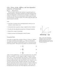
• <strong>Gear</strong> 3 is an idler so it transmits no power to its shaft<br />
t<br />
F43 t<br />
F23 F 43<br />
4<br />
r<br />
F32 F 23<br />
y<br />
Fb3 b<br />
r<br />
F23 r<br />
F43 t<br />
F32 F 32<br />
F b3<br />
x<br />
Fb3
Hence<br />
for equilibrium<br />
in the x direction only<br />
F t 43 =<br />
F r 43 =<br />
F x b3 − F t 23 − F t 43 =0 ⇒<br />
F y<br />
b3 + F r 23 − F r 43 =0 ⇒ F y<br />
b3 =0kN<br />
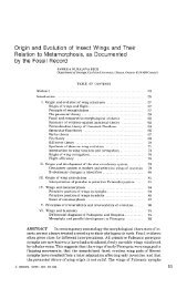
T c4<br />
� 4<br />
F3b =<br />
y<br />
Fc4 c<br />
r<br />
F34 F c4<br />
x<br />
Fc4 F 34<br />
t<br />
F34 Tc4 − F t 34d4<br />
2 =0<br />
Tc4 =<br />
5