Safety & Operating Instructions - Crowder Hydraulic Tools
Safety & Operating Instructions - Crowder Hydraulic Tools
Safety & Operating Instructions - Crowder Hydraulic Tools

Create successful ePaper yourself
Turn your PDF publications into a flip-book with our unique Google optimized e-Paper software.
LPHB<br />
©Copyright 2005<br />
ATLAS COPCO CONSTRUCTION TOOLS AB 2005-09<br />
NACKA • SWEDEN No 3392 5039 01 a<br />
www.atlascopco.com
1 English<br />
INTRODUCTION ....................................................................................................................... 2<br />
SAFETY INSTRUCTIONS ........................................................................................................ 2<br />
Introduction to safety ....................................................................................................... 2<br />
<strong>Safety</strong> symbols used ........................................................................................................ 2<br />
General safety rules.......................................................................................................... 3<br />
Protective equipment........................................................................................................ 3<br />
MARKINGS ............................................................................................................................... 4<br />
Identification...................................................................................................................... 4<br />
CE ....................................................................................................................................... 4<br />
<strong>Safety</strong> signs on the Posthole Borer ................................................................................ 4<br />
GENERAL INFORMATION....................................................................................................... 4<br />
OPERATING INSTRUCTIONS ................................................................................................. 5<br />
Torque setting ................................................................................................................... 5<br />
Starting/stopping the Posthole Borer ............................................................................. 5<br />
Connecting/disconnecting hoses ................................................................................... 6<br />
Service schedules............................................................................................................. 7<br />
Scrapping and waste disposal ........................................................................................ 7<br />
TROUBLE SHOOTING ............................................................................................................. 8<br />
TECHNICAL DATA................................................................................................................... 8<br />
Augers and bits ................................................................................................................. 8<br />
Noise declaration statement ............................................................................................ 8
English 2<br />
These operating and safety instructions must be read before operating the machine. <strong>Instructions</strong><br />
for operation and basic maintenance are included. The purpose of this booklet is to give<br />
the machine user an understanding of how to safely and efficiently use and maintain the machine.<br />
!" #<br />
SAFETY INSTRUCTIONS<br />
• Before starting, read all instructions<br />
carefully<br />
• Special attention must be<br />
paid to information<br />
alongside this symbol<br />
• Only use Atlas Copco genuine parts<br />
To reduce the risk of serious injury to yourself or others, read these safety instructions before<br />
using the Posthole Borer. Post these safety instructions at work locations, provide copies to<br />
employees, and make sure that everyone reads the safety instructions before using the Posthole<br />
Borer. Comply with all safety regulations.<br />
These instructions have been compiled from international safety standards and form part of<br />
the operating instructions. Signs and decals that are important for your safety and the care of<br />
the Posthole Borer are included with each Posthole Borer. Make sure that they are legible.<br />
New decals can be ordered using the spare parts list.<br />
$ %<br />
The indications DANGER, WARNING and CAUTION, as used in the safety instructions, have<br />
the following meanings:<br />
DANGER Immediate hazard which<br />
WILL result in serious or<br />
fatal injury if the warning is<br />
not observed<br />
WARNING Hazard or hazardous<br />
procedure which COULD<br />
result in serious or fatal<br />
injury if the warning is not<br />
observed<br />
CAUTION Hazard or hazardous<br />
procedure which COULD<br />
result in injury or damaged<br />
equipment if the warning is<br />
not observed
3 English<br />
&<br />
• The Posthole Borer must only be used for its purpose<br />
• Learn how the power source is switched off in the event of an emergency<br />
• Only qualified and trained persons may operate or maintain the Posthole Borer<br />
• The Posthole Borer must always be operated by two persons<br />
• Drill only in places, where both operators can stand firmly on the ground outside of the<br />
drill<br />
• Never operate with loose clothing on, as this might get in touch with the auger<br />
• Do not use the Posthole Borer in an explosive environment<br />
• Never change auger or bit, when the Posthole Borer is connected to the power source<br />
• Keep the Posthole Borer in a safe place out of the reach of children, locked up<br />
• Pay attention and look at what you are doing<br />
• Use your common sense<br />
• Do not use the Posthole Borer when you are tired or under influence of drugs, alcohol or<br />
anything else that may influence your vision, reaction or judgement<br />
• Always disconnect the hydraulic circuit before dismounting hoses or servicing the Posthole<br />
Borer<br />
• Never leave the Posthole Borer connected with the power source turned on<br />
• Regular maintenance is prerequisite for machine safety. Carefully follow the operating<br />
instructions. Replace damaged and worn components in good time. For major service to<br />
the Posthole Borer, contact your nearest authorized workshop. When cleaning mechanical<br />
parts with solvent, make sure to comply with current health and safety regulations and<br />
ensure sufficient ventilation<br />
' ( $<br />
Always use approved personal protective equipment. Operators and other staff in the proximity<br />
areas where work is in progress must as a minimum use the following approved protective<br />
equipment:<br />
• Hearing protection<br />
• Protective helmet<br />
• <strong>Safety</strong> glass with side protection<br />
• Respiratory protection when appropriate<br />
• Protective gloves<br />
• Protective boots
) ! * &<br />
English 4<br />
The CE marking verifies that the machine is CE approved. The marking is on the ID-tag. See<br />
the “Declaration of Conformity” supplied with the Posthole Borer for more information.<br />
& ! " ) !<br />
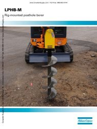
The Atlas Copco handheld Posthole Borer is a powerful hydraulic tool designed for twin-operator<br />
use for the drilling of holes down to a depth of 1-1.3 m with standard Atlas Copco augers<br />
in sizes from ø90 to ø350 mm.<br />
The Posthole Borer has reversible rotation and stops automatically, when the lever is released.<br />
The Posthole Borer has an integrated adjustable torque limiter, which prevents the Posthole<br />
Borer from rotating, if the auger hits a stone.
5 English<br />
! &<br />
To achieve standard performance, the Atlas Copco Posthole Borer requires a nominal oil<br />
supply from the power source of 15-30 l.p.m. at a pressure of 100-140 bar. The hydraulic oil<br />
filter must have a filter rating of 25 Micron or better.<br />
Hoses<br />
For connection use high-pressure hoses<br />
(inside diameter ½”) which, as a minimum,<br />
are designed for a working pressure of<br />
140 bar. We recommend the use of double<br />
wire-braided hoses that better stand outside<br />
wear. The Posthole Borer socket “P”<br />
is oil inlet (pump) and the socket “T” is oil<br />
outlet (tank).<br />
(<br />
The torque limiter positioned in the valve<br />
block can be adjusted by means of a 13<br />
mm spanner and a 4 mm Allen key.<br />
Place the Posthole Borer safely in a vice<br />
(or other fixture), so that rotation is completely<br />
stopped.<br />
Screw in the torque limiter to increase the<br />
torque and screw out to reduce the torque.<br />
Mount a pressure gauge in the pressure<br />
line from the power source and read the<br />
pressure, when the handle is activated.<br />
The torque varies with the pressure, as for<br />
example:<br />
Pressure 140 bar = Torque 315 Nm<br />
Pressure 100 bar = Torque 225 Nm<br />
Pressure 70 bar = Torque 160 Nm<br />
+ ,<br />
1. Connect the hoses to the power<br />
source by means of the quickrelease<br />
couplings<br />
2. Make sure that the Posthole Borer is<br />
supplied with correct flow according<br />
to the technical data<br />
3. Make sure that the torque limiter has<br />
not been set at a higher pressure<br />
than stated in the technical data<br />
4. Make sure that the drilling does not<br />
involve the risk of getting into con-<br />
tact with electric cables, gas mains,<br />
water pipes etc.<br />
5. Make sure that both operators are<br />
familiar with the operation of the tool<br />
6. If the auger hits a stone, hard<br />
ground etc., the rotation may stop<br />
immediately and give a hard reaction.<br />
It is therefore required that both<br />
operators hold firmly onto all four<br />
handles during operation in order to<br />
compensate for a sudden reaction<br />
7. Start the power source and allow it<br />
to run for a few minutes to warm the<br />
hydraulic oil<br />
8. Activate the control valve of the<br />
power source to start the hydraulic<br />
oil flow<br />
9. Start the Posthole Borer<br />
10. When work is finished, activate the<br />
control valve to stop the hydraulic oil<br />
flow<br />
11. Stop the engine of the power source<br />
Flow rates<br />
The European <strong>Hydraulic</strong> Tool Manufacturers<br />
Association (E.H.T.M.A.) has categorised<br />
hydraulic power packs and tools in<br />
terms of flow rate and working pressure.<br />
Our Post Puller is categorised by the<br />
E.H.T.M.A. as C, D and E.<br />
Note: The Atlas Copco hydraulic Post<br />
Puller is clearly marked with<br />
E.H.T.M.A. categories. It is important<br />
that any power source<br />
used with the Post Puller is of a<br />
compatible category. If any doubt,<br />
consult your Atlas Copco dealer.
WARNING<br />
The setting of the pressure relief<br />
valve on the power source can in<br />
some cases be higher than the prescribed<br />
max. pressure according to<br />
the E.H.T.M.A. category.<br />
A too high pressure relief valve setting<br />
can harm the Posthole Borer.<br />
Readjust the pressure relief valve<br />
on the power source if the technical<br />
specifications of the Posthole Borer<br />
prescribe a lower pressure relief<br />
valve setting than the standard<br />
setting of the power source.<br />
CAUTION<br />
Ensure that any power source you<br />
plan to use is compatible with the<br />
Posthole Borer you are using.<br />
Non-compatible power sources<br />
might harm both the Posthole Borer<br />
and the power source.<br />
Check the section Flow rates in this<br />
instruction book and compare the<br />
flow rate with the technical specifications<br />
in the instruction book for<br />
the power source.<br />
+<br />
Connecting hoses<br />
1. Prepare the power source<br />
a) Turn the by-pass valve to the<br />
OFF position<br />
b) Stop the engine<br />
2. Inspect the couplings<br />
a) Ensure that the couplings are<br />
clean and serviceable<br />
3. Connect the hoses to the Posthole<br />
Borer<br />
a) Attach the return line<br />
b) Attach the feed line<br />
c) Rotate the collar on the female<br />
coupling to secure the coupling<br />
English 6<br />
4. Check the hydraulic oil level<br />
a) Start the engine and run the<br />
power source to fill up the hydraulic<br />
circuit<br />
b) Check the hydraulic oil level<br />
Disconnecting hoses<br />
1. Prepare the power source<br />
a) Turn the by-pass valve to the<br />
OFF position<br />
b) Stop the engine<br />
2. Remove the hoses<br />
a) Rotate the collar on the female<br />
coupling<br />
b) Release the return line<br />
c) Release the feed line<br />
3. Install protective caps over the ports<br />
to prevent contamination<br />
Note: The couplings are unlocked by moving<br />
the collar back on the coupling<br />
WARNING<br />
Do not disconnect the hoses, when<br />
the power source is running, or if<br />
the hydraulic oil is hot. Hot<br />
hydraulic oil might cause serious<br />
burns.<br />
WARNING<br />
Fine jets of hydraulic oil at high<br />
pressure can penetrate the skin. Do<br />
not use your fingers to check for<br />
hydraulic oil leaks. Do not put your<br />
face close to suspected leaks. Hold<br />
a piece of cardboard close to suspected<br />
leaks and then inspect the<br />
cardboard for signs of hydraulic oil.<br />
If hydraulic oil penetrates your skin,<br />
get medical help quickly.
7 English<br />
Daily<br />
'<br />
The daily maintenance of the Posthole<br />
Borer and the quick-release couplings is<br />
confined to cleaning after use.<br />
1. Check the hoses regularly for damages.<br />
Replace if necessary<br />
2. Clean the quick-release couplings<br />
before use. Use this maintenance<br />
schedule to maximize service life<br />
Monthly<br />
1. Perform a thorough inspection of the<br />
hydraulic hoses and fittings as described<br />
above<br />
WARNING<br />
Maintenance must be done only by<br />
suitably qualified and competent<br />
persons.<br />
Before doing any maintenance,<br />
make sure that the Posthole Borer<br />
is safe and correctly sited on level<br />
ground.<br />
Recommended hydraulic oil<br />
In order to protect the environment, Atlas<br />
Copco recommends the use of biologically<br />
degradable hydraulic oil.<br />
Viscosity (preferred)....................20-40 cSt<br />
Viscosity (permitted) .................15-100 cSt<br />
Viscosity index ............................. Min. 100<br />
Standard mineral or synthetic oil can be<br />
used.<br />
The Posthole Borer must not be used, if<br />
the oil viscosity fails to remain within the<br />
permitted area, or if the working temperature<br />
of the oil does not fall between 20-<br />
40°C.<br />
Used and worn out parts must be treated<br />
and disposed of in such a way that the<br />
greatest possible part of them can be recycled<br />
and the influence on the environment<br />
kept as low as possible.<br />
-
WARNING<br />
Problem Cause Solution<br />
&<br />
Maintenance must be done only by suitably qualified and competent persons.<br />
Posthole Borer will not operate<br />
Posthole Borer operates<br />
slowly or erratically<br />
Posthole Borer operates<br />
backwards<br />
! ! !<br />
English 8<br />
Improper power source Verify that the power source<br />
meets the specifications<br />
Oil level too low Check oil level. Check system<br />
for leaks<br />
Incorrect hydraulic oil viscosity<br />
Use hydraulic oil with correct<br />
viscosity<br />
Cold hydraulic oil Allow oil to warm up to operating<br />
temperature<br />
Power source not adjusted<br />
correctly<br />
See the operating manual for<br />
the power source and set the<br />
flow and pressure<br />
Oil level too low Check oil level. Check system<br />
for leaks<br />
Air in the hydraulic system See the operating manual for<br />
the power source in order to<br />
remove air from the system<br />
Incorrect hydraulic oil viscosity<br />
Use hydraulic oil with correct<br />
viscosity<br />
Hose connections reversed Depressurize the hydraulic<br />
system and switch the hose<br />
connections<br />
Weight without auger.......................................................................................................... 20 kg<br />
Measurement (LxHxW)............................................................................. 1085 x 475 x 300 mm<br />
Oil flow ......................................................................................................................15-30 l.p.m.<br />
Working pressure......................................................................................................100-140 bar<br />
Max. back pressure in return line (measured at tool)........................................................50 bar<br />
Max. rotational speed 15 l.p.m........................................................ 90 1/min.<br />
20 l.p.m...................................................... 125 1/min.<br />
30 l.p.m...................................................... 188 1/min.<br />
Max. torque.................................................................................................... 315 Nm at 140 bar<br />
(Previous models equipped with OMR 250 motor: Max. pressure setting 80 bar)<br />
Extension rod..................................................................................................................500 mm
9 English<br />
! %<br />
Auger ø90 x 870 mm .............................................................................................3378 0050 45<br />
Bit set incl. bolts.....................................................................................................3378 0999 28<br />
Auger ø150 x 870 mm ...........................................................................................3378 0050 46<br />
Bit set incl. bolts.....................................................................................................3378 0999 30<br />
Auger ø200x 870 mm ............................................................................................3378 0050 44<br />
Bit set incl. bolts.....................................................................................................3378 0999 31<br />
Auger ø250 x 870 mm ...........................................................................................3378 0050 47<br />
Bit set incl. bolts.....................................................................................................3378 0999 32<br />
Auger ø280 x 870 mm ...........................................................................................3378 0050 49<br />
Bit set incl. bolts.....................................................................................................3378 0999 33<br />
Auger ø350 x 870 mm ...........................................................................................3378 0050 48<br />
Bit set incl. bolts.....................................................................................................3378 0999 34<br />
Tip for Posthole Borer (all sizes) ...........................................................................3378 0999 36<br />
Extension rod 0.5 m...............................................................................................3378 0050 55<br />
$<br />
Sound pressure level at work station LPA<br />
IMPORTANT<br />
< 85 dB<br />
We, Atlas Copco Construction <strong>Tools</strong> AB, cannot be held liable for the consequences<br />
of using the declared values, instead of values reflecting the actual exposure,<br />
in an individual risk assessment in a work place situation, over which we have no<br />
control.