DS 5-4 Transformers (Data Sheet) - FM Global
DS 5-4 Transformers (Data Sheet) - FM Global
DS 5-4 Transformers (Data Sheet) - FM Global

You also want an ePaper? Increase the reach of your titles
YUMPU automatically turns print PDFs into web optimized ePapers that Google loves.
<strong>FM</strong> <strong>Global</strong><br />
Property Loss Prevention <strong>Data</strong> <strong>Sheet</strong>s 5-4<br />
TRANSFORMERS<br />
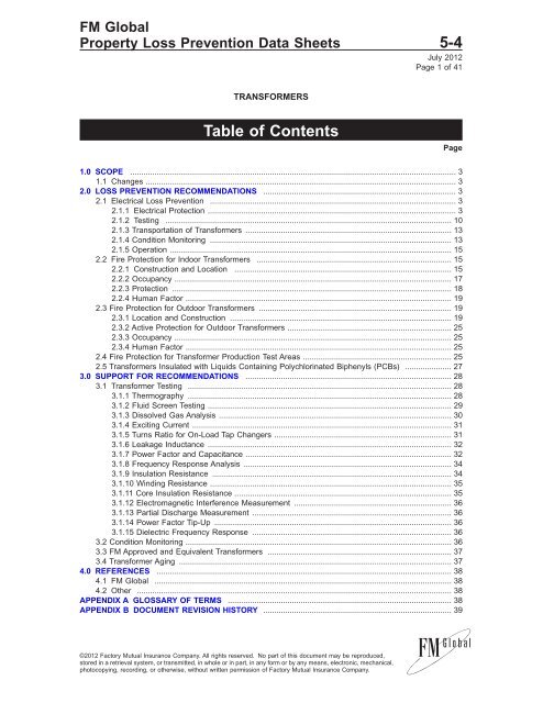
Table of Contents<br />
July 2012<br />
Page 1 of 41<br />
1.0 SCOPE ................................................................................................................................................... 3<br />
1.1 Changes ............................................................................................................................................ 3<br />
2.0 LOSS PREVENTION RECOMMENDATIONS ....................................................................................... 3<br />
2.1 Electrical Loss Prevention ............................................................................................................... 3<br />
2.1.1 Electrical Protection ................................................................................................................ 3<br />
2.1.2 Testing ................................................................................................................................. 10<br />
2.1.3 Transportation of <strong>Transformers</strong> ............................................................................................. 13<br />
2.1.4 Condition Monitoring ............................................................................................................. 13<br />
2.1.5 Operation ............................................................................................................................... 15<br />
2.2 Fire Protection for Indoor <strong>Transformers</strong> ........................................................................................ 15<br />
2.2.1 Construction and Location .................................................................................................. 15<br />
2.2.2 Occupancy ............................................................................................................................. 17<br />
2.2.3 Protection .............................................................................................................................. 18<br />
2.2.4 Human Factor ........................................................................................................................ 19<br />
2.3 Fire Protection for Outdoor <strong>Transformers</strong> ....................................................................................... 19<br />
2.3.1 Location and Construction .................................................................................................... 19<br />
2.3.2 Active Protection for Outdoor <strong>Transformers</strong> .......................................................................... 25<br />
2.3.3 Occupancy ............................................................................................................................. 25<br />
2.3.4 Human Factor ........................................................................................................................ 25<br />
2.4 Fire Protection for Transformer Production Test Areas ................................................................... 25<br />
2.5 <strong>Transformers</strong> Insulated with Liquids Containing Polychlorinated Biphenyls (PCBs) ..................... 27<br />
3.0 SUPPORT FOR RECOMMENDATIONS ............................................................................................. 28<br />
3.1 Transformer Testing ....................................................................................................................... 28<br />
3.1.1 Thermography ....................................................................................................................... 28<br />
3.1.2 Fluid Screen Testing .............................................................................................................. 29<br />
3.1.3 Dissolved Gas Analysis ......................................................................................................... 30<br />
3.1.4 Exciting Current ..................................................................................................................... 31<br />
3.1.5 Turns Ratio for On-Load Tap Changers ................................................................................ 31<br />
3.1.6 Leakage Inductance .............................................................................................................. 32<br />
3.1.7 Power Factor and Capacitance ............................................................................................. 32<br />
3.1.8 Frequency Response Analysis .............................................................................................. 34<br />
3.1.9 Insulation Resistance ............................................................................................................ 34<br />
3.1.10 Winding Resistance ............................................................................................................. 35<br />
3.1.11 Core Insulation Resistance .................................................................................................. 35<br />
3.1.12 Electromagnetic Interference Measurement ....................................................................... 36<br />
3.1.13 Partial Discharge Measurement .......................................................................................... 36<br />
3.1.14 Power Factor Tip-Up ........................................................................................................... 36<br />
3.1.15 Dielectric Frequency Response .......................................................................................... 36<br />
3.2 Condition Monitoring ........................................................................................................................ 36<br />
3.3 <strong>FM</strong> Approved and Equivalent <strong>Transformers</strong> ................................................................................... 37<br />
3.4 Transformer Aging ........................................................................................................................... 37<br />
4.0 REFERENCES ..................................................................................................................................... 38<br />
4.1 <strong>FM</strong> <strong>Global</strong> ...................................................................................................................................... 38<br />
4.2 Other .............................................................................................................................................. 38<br />
APPENDIX A GLOSSARY OF TERMS ..................................................................................................... 38<br />
APPENDIX B DOCUMENT REVISION HISTORY ..................................................................................... 39<br />
©2012 Factory Mutual Insurance Company. All rights reserved. No part of this document may be reproduced,<br />
stored in a retrieval system, or transmitted, in whole or in part, in any form or by any means, electronic, mechanical,<br />
photocopying, recording, or otherwise, without written permission of Factory Mutual Insurance Company.<br />
Page
5-4 <strong>Transformers</strong><br />
Page 2 <strong>FM</strong> <strong>Global</strong> Property Loss Prevention <strong>Data</strong> <strong>Sheet</strong>s<br />
APPENDIX C BIBLIORGRAPHY ................................................................................................................ 40<br />
List of Figures<br />
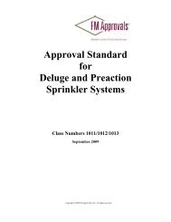
Fig. 1A. Typical protective scheme for a two-winding, delta-wye connected transformer up to<br />
10,000 kVA in size using fuses on the primary of the transformers ................................................. 4<br />
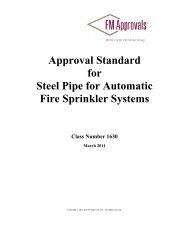
Fig. 1B. Typical protective scheme for a two-winding, delta-wye connected transformer up to<br />
10,000 kVA in size using a circuit breaker on the primary of the transformers ............................... 5<br />
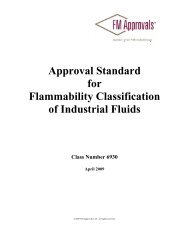
Fig. 1C. Typical protective scheme for a two-winding, delta-wye connected transformer<br />
greater than 10,000 kVA in size ...................................................................................................... 6<br />
Fig. 1D. Typical protective scheme for transformers greater than 10,000 kVA in size with a<br />
secondary selective system ............................................................................................................ 7<br />
Fig. 1E. Alternative protective devices that achieve the same level of protection as those<br />
shown in Figures 1A, 1B, and 1C ..................................................................................................... 8<br />
Fig. 2a. Locations for transformer buildings and rooms .............................................................................. 16<br />
Fig. 2b. Minimum horizontal separation distance between outdoor liquid-insulated transformers<br />
and exposed walls of main buildings .............................................................................................. 20<br />
Fig. 2c. Use of 2-hour fire barriers and separation distances for protection of exposed main<br />
building walls ............................................................................................................................... 21<br />
Fig. 2d. Determination of exposed roof area ........................................................................................... 22<br />
Fig. 2e. Fire barriers for multiple outdoor transformers ............................................................................ 24<br />
Fig. 2f. Roof level sprinkler option ............................................................................................................. 26<br />
Fig. 2g. Local sprinkler option ....................................................................................................................... 26<br />
List of Tables<br />
Table 1. Recommended Additional Protection for Specialty <strong>Transformers</strong> .................................................. 10<br />
Table 2. Routine Off-line Tests ...................................................................................................................... 12<br />
Table 3. Focused Off-Line Tests ................................................................................................................... 13<br />
Table 4. Recommended Construction for Transformer Buildings and Rooms ............................................. 16<br />
Table 5. Separation for Exposure Protection of Main Buildong Walls (also refer to Figure 2b) ................. 20<br />
Table 6. Separation and Extent of 2-hour Fire Barriers for Protection of Main Building Walls<br />
(for dimensions refer to Figure 2c) ............................................................................................... 21<br />
Table 7. Transformer Fire Exposure to Noncombustible Building Roof Where Separation from Wall<br />
is Based on a 3-hour Fire Barrier or Water Spray Protection ........................................................ 22<br />
Table 8. Minimum Separation Distances Between Adjacent <strong>Transformers</strong> .................................................. 23<br />
Table 9. Sprinkler Densities for Roof Level and Local Protection Options for Transformer Production<br />
Test Areas (see Figures 2f and 2g) .............................................................................................. 26<br />
Table 10. General Criteria for Evaluating Thermographic Scans ................................................................. 29<br />
Table 11. Tests Typically Included in a Mineral Oil Screen Test .................................................................. 29<br />
Table 12. Gases Included in a Typical DGA Report ..................................................................................... 30<br />
Table 13. Gases Represented by Chemical Formulas ................................................................................. 30<br />
Table 14. General Rules for Interpreting Power Factor Results .................................................................. 33<br />
Table 15. Power Factor Limits for <strong>Transformers</strong> .......................................................................................... 33<br />
Table 16. Interpretation of the Changes in Current Between Tests ............................................................. 33<br />
Table 17. Power Factor Limits for Dry-Type <strong>Transformers</strong> ........................................................................... 33<br />
©2012 Factory Mutual Insurance Company. All rights reserved.
<strong>Transformers</strong> 5-4<br />
<strong>FM</strong> <strong>Global</strong> Property Loss Prevention <strong>Data</strong> <strong>Sheet</strong>s Page 3<br />
1.0 SCOPE<br />
This data sheet contains loss prevention recommendations related to the fire protection of ALL types of<br />
transformers. It also contains loss prevention recommendations related to electrical protection, electrical<br />
testing, maintenance, and operation for large and critical distribution, power, and specialty transformers ONLY.<br />
For loss prevention recommendations related to electrical protection, electrical testing, maintenance, and<br />
operation of smaller and less critical transformers, see <strong>DS</strong> 5-20, Electrical Testing.<br />
Specialty transformers include network transformers, rectifier transformers, arc furnace transformers,<br />
induction furnace transformers, generator step-up transformers, series reactors, and shunt reactors.<br />
1.1 Changes<br />
July 2012. Major changes include the following:<br />
• The electrical testing, electrical protection, maintenance and operation sections of this data sheet have<br />
been substantially revised.<br />
• This data sheet no longer refers to <strong>DS</strong> 5-20 for electrical testing recommendations.<br />
• Recommendations related to specialty transformers have been added to this data sheet.<br />
• Fire protection recommendations have been re-organized for better clarity.<br />
• Total flooding gaseous systems are no longer recommended as alternatives to sprinklers for protection<br />
of indoor transformers.<br />
• Sprinkler protection criteria for indoor test areas have been revised.<br />
• Emergency drainage is recommended for indoor transformers where sprinkler protection is provided.<br />
2.0 LOSS PREVENTION RECOMMENDATIONS<br />
2.1 Electrical Loss Prevention<br />
2.1.1 Electrical Protection<br />
2.1.1.1 Perform an engineering analysis to determine the most appropriate protective scheme for each<br />
transformer, taking into account the following factors:<br />
A. The criticality of the transformer<br />
B. The lead time required to replace or repair the transformer<br />
C. The fire exposure presented by the transformer to buildings and equipment<br />
D. The effect of transformer failure on system integrity and reliability<br />
E. The service requirements of the transformer (e.g., is the transformer required to operate in a high fault<br />
environment or is it exposed to high levels of harmonics, overvoltages, and lightning?)<br />
F. The condition of the transformer (e.g., is the transformer approaching the end of its useful life, is it<br />
operated in a harsh environment, has the transformer been compromised from previous faults?)<br />
See Figure 1A for a typical protective scheme for a two-winding, delta-wye connected transformer up to 10,000<br />
kVA in size using fuses on the primary of the transformers.<br />
See Figure 1B for a typical protective scheme for a two-winding, delta-wye connected transformer up to<br />
10,000 kVA in size using a circuit breaker on the primary of the transformers.<br />
See Figure 1C for a typical protective scheme for a two-winding, delta-wye connected transformer greater<br />
than 10,000 kVA in size.<br />
See Figure 1D for a typical protective scheme for transformers greater than 10,000 kVA in size with a<br />
secondary selective system.<br />
See Figure 1E for some alternative protective devices that achieve the same level of protection as the<br />
schemes shown in Figures 1A, 1B, and 1C.<br />
©2012 Factory Mutual Insurance Company. All rights reserved.
5-4 <strong>Transformers</strong><br />
Page 4 <strong>FM</strong> <strong>Global</strong> Property Loss Prevention <strong>Data</strong> <strong>Sheet</strong>s<br />
Device<br />
No.<br />
Description Dry<br />
26 Liquid thermal<br />
device<br />
49 Winding thermal<br />
device<br />
51N 1<br />
Time delay<br />
overcurrent relay.<br />
(Ground fault<br />
protection of<br />
transformer wye<br />
winding and<br />
through faults.)<br />
51TL Time delay<br />
overcurrent relay.<br />
(Transformer<br />
overload protection)<br />
63 Sudden pressure<br />
relay<br />
Liquid<br />
(MVA)<br />
1–5 5–10<br />
I I<br />
I I<br />
T T T<br />
T T T<br />
71 Liquid Level Device I I<br />
Notes:<br />
A—Alarm, I—Indication, T—Trip<br />
1. Devices 50G, 50N/51N, 50NY/51NY, 67N and 87TN are<br />
alternatives. (See Fig 1E.)<br />
T<br />
Fig. 1A.Typical protective scheme for a two-winding, delta-wye connected transformer up to 10,000 kVA in size using fuses<br />
on the primary of the transformers<br />
©2012 Factory Mutual Insurance Company. All rights reserved.
<strong>Transformers</strong> 5-4<br />
<strong>FM</strong> <strong>Global</strong> Property Loss Prevention <strong>Data</strong> <strong>Sheet</strong>s Page 5<br />
Device<br />
No.<br />
Description Dry<br />
26 Liquid thermal<br />
device.<br />
49 Winding thermal<br />
device.<br />
Instantaneous<br />
ground overcurrent<br />
relay. (High<br />
magnitude ground<br />
fault protection of<br />
transformer delta<br />
winding and leads.)<br />
50TF Instantaneous<br />
overcurrent relay.<br />
(High magnitude<br />
transformer internal<br />
phase fault<br />
protection.)<br />
51N 1<br />
Time delay<br />
overcurrent relay.<br />
(Ground fault<br />
protection of<br />
transformer wye<br />
winding and<br />
through faults.)<br />
Time delay ground<br />
overcurrent relay.<br />
(Ground fault<br />
protection of<br />
transformer delta<br />
winding and leads.)<br />
51TF Time delay<br />
overcurrent relay.<br />
(Phase through<br />
fault protection.)<br />
51TL Time delay<br />
overcurrent relay.<br />
(Transformer<br />
overload protection)<br />
63 Sudden pressure<br />
relay<br />
50ND 2<br />
51ND 2<br />
Liquid<br />
(MVA)<br />
1–5 5–10<br />
I I<br />
I I<br />
T T T<br />
T T T<br />
T T T<br />
T T T<br />
T T T<br />
T T T<br />
71 Liquid level device I I<br />
Notes:<br />
A—Alarm, I—Indication, T—Trip<br />
1. Devices 50G, 50N/51N, 50NY/51NY, 67N and 87TN are alternatives. (See Fig 1E.)<br />
2. Device 50GD is an alternative to 50ND/51ND. (See Fig 1E.)<br />
T<br />
Fig. 1B. Typical protective scheme for a two-winding, delta-wye connected transformer up to 10,000 kVA in size using a<br />
circuit breaker on the primary of the transformers<br />
©2012 Factory Mutual Insurance Company. All rights reserved.
5-4 <strong>Transformers</strong><br />
Page 6 <strong>FM</strong> <strong>Global</strong> Property Loss Prevention <strong>Data</strong> <strong>Sheet</strong>s<br />
Device<br />
No.<br />
Description Action<br />
24 Volts/hertz relay (For unit<br />
connected transformers only)<br />
T<br />
26 Liquid thermal device A<br />
49 Winding thermal device A<br />
50ND 2<br />
Instantaneous ground<br />
overcurrent relay. (High<br />
magnitude ground fault<br />
protection of transformer delta<br />
winding and leads.)<br />
T<br />
50TF Instantaneous overcurrent relay.<br />
(High magnitude transformer<br />
internal phase fault protection)<br />
T<br />
51N 1<br />
Time delay overcurrent relay.<br />
(Ground fault protection of<br />
transformer wye winding and<br />
through faults.)<br />
T<br />
51ND 2 Time delay ground overcurrent<br />
relay. (Ground fault protection<br />
of transformer delta winding<br />
and leads.)<br />
T<br />
51TF Time delay overcurrent relay.<br />
(Phase through fault<br />
protection.)<br />
T<br />
51TL Time delay overcurrent relay.<br />
(Transformer overload<br />
protection)<br />
T<br />
63 Sudden pressure relay T<br />
71 Liquid Level Device I<br />
87T Transformer differential relay<br />
(Fault protection for transformer<br />
internal faults)<br />
T<br />
87TN 3 Transformer ground differential<br />
relay (Ground fault protection of<br />
transformer wye winding<br />
internal faults)<br />
T<br />
Notes:<br />
A—Alarm, I—Indication, T—Trip<br />
1. Devices 50G, 50N/51N, and 50NY/51NY are alternatives. (See Fig 1E.)<br />
2. Device 50GD is an alternative to 50ND/51ND. (See Fig 1E.)<br />
3. Device 67N is an alternative to 87TN. (See Fig 1E.)<br />
Fig. 1C. Typical protective scheme for a two-winding, delta-wye connected transformer greater than 10,000 kVA in size<br />
©2012 Factory Mutual Insurance Company. All rights reserved.
<strong>Transformers</strong> 5-4<br />
<strong>FM</strong> <strong>Global</strong> Property Loss Prevention <strong>Data</strong> <strong>Sheet</strong>s Page 7<br />
Note:<br />
Electrical protection shown for 10-MVA and larger transformers.<br />
Protection should be chosen per Fig. 1A, 1B, or 1C depending<br />
upon transformer size.<br />
Fig. 1D. Typical protective scheme for transformers greater than 10,000 kVA in size with a secondary selective system<br />
©2012 Factory Mutual Insurance Company. All rights reserved.
5-4 <strong>Transformers</strong><br />
Page 8 <strong>FM</strong> <strong>Global</strong> Property Loss Prevention <strong>Data</strong> <strong>Sheet</strong>s<br />
Device<br />
Description<br />
No.<br />
24 Volts/hertz relay (For unit connected<br />
transformers only)<br />
26 Liquid thermal device<br />
49 Winding thermal device<br />
50G 1<br />
Zero sequence instantaneous ground<br />
overcurrent relay. (Ground fault<br />
protection of wye winding and through<br />
faults)<br />
50GD 2 Zero sequence instantaneous ground<br />
overcurrent relay. (Ground fault<br />
protection of transformer delta winding.)<br />
50N Instantaneous ground overcurrent relay.<br />
(High magnitude ground fault protection<br />
of wye winding and through faults.)<br />
50ND Instantaneous ground overcurrent relay.<br />
(High magnitude ground fault protection<br />
of transformer delta winding and leads.)<br />
50NY Instantaneous ground overcurrent relay.<br />
(High magnitude ground fault protection<br />
of wye winding and through faults.)<br />
50TF Instantaneous overcurrent relay. (High<br />
magnitude transformer internal phase<br />
fault protection)<br />
51N Time delay overcurrent relay. (Ground<br />
fault protection of transformer wye<br />
winding and through faults.)<br />
51ND Time delay ground overcurrent relay.<br />
(Ground fault protection of transformer<br />
delta winding and leads.)<br />
51NY Time delay overcurrent relay. (Ground<br />
fault protection of transformer wye<br />
winding and through faults.)<br />
51TF Time delay overcurrent relay. (Phase<br />
through fault protection.)<br />
51TL Time delay overcurrent relay.<br />
(Transformer overload protection)<br />
63 Sudden pressure relay<br />
67N 3<br />
AC Directional neutral overcurrent relay.<br />
(Ground fault protection of transformer<br />
wye winding internal faults)<br />
71 Liquid Level Device<br />
87T Transformer differential relay (Fault<br />
protection for transformer internal faults)<br />
87TN Transformer ground differential relay<br />
(Ground fault protection of transformer<br />
wye winding internal faults)<br />
Notes:<br />
1. Devices 50G, 50N/51N, 50NY/51NY are alternatives.<br />
2. Device 50GD is an alternative to 50ND/51ND.<br />
3. Device 67N is an alternative to 87TN.<br />
Fig. 1E. Alternative protective devices that achieve the same level of protection as those shown in Figures 1A, 1B, and<br />
1C<br />
©2012 Factory Mutual Insurance Company. All rights reserved.
<strong>Transformers</strong> 5-4<br />
<strong>FM</strong> <strong>Global</strong> Property Loss Prevention <strong>Data</strong> <strong>Sheet</strong>s Page 9<br />
2.1.1.2 Provide overvoltage protection for all transformers in accordance with <strong>Data</strong> <strong>Sheet</strong> 5-11, Lightning<br />
and Surge Protection for Electrical Systems.<br />
2.1.1.3 Improve the overvoltage protection for transformers that are approaching the end of their useful life.<br />
Consult a qualified installation or repair company for upgrade options.<br />
2.1.1.4 Provide differential protection to cover all the windings on multiple winding power transformers,<br />
including specialty transformers such as rectifier, induction, and arc furnace transformers. Where the high<br />
magnetic fields of specialty transformers prohibit the use of conventional iron core current transformers, use<br />
Rogowski Coil current sensors to implement differential protection.<br />
2.1.1.5 Provide overcurrent and ground fault protection for the tertiary winding of three-winding transformers<br />
and autotransformers.<br />
2.1.1.6 Do not reenergize transformers after the operation of protective devices until it has been determined<br />
that the transformer has not suffered internal damage and any external faults have been removed. At a<br />
minimum, perform a dissolved gas analysis test (DGA) to determine if the transformer has suffered internal<br />
damage. Additional testing may be needed depending on the results of the DGA test (see Section 2.1.2).<br />
Exercise care when taking a DGA sample immediately following a fault. It may be prudent to wait several hours<br />
after the fault since fault gases may not have enough time to migrate through the bulk of the oil. Taking a<br />
DGA sample too early can produce misleading results.<br />
2.1.1.7 Provide an arc-monitoring system (e.g., ABB Arc Guard System) or <strong>FM</strong> Approved equivalent to detect<br />
arcing faults in transformer vaults with exposed energized components. Provide this additional protection<br />
when the ground fault relay cannot be set low enough to detect ground fault current due to neutral imbalance<br />
current flow.<br />
Table 1 contains a list of specialty transformers and the additional protection recommended for them.<br />
©2012 Factory Mutual Insurance Company. All rights reserved.
5-4 <strong>Transformers</strong><br />
Page 10 <strong>FM</strong> <strong>Global</strong> Property Loss Prevention <strong>Data</strong> <strong>Sheet</strong>s<br />
Table 1. Recommended Additional Protection for Specialty <strong>Transformers</strong><br />
Transformer<br />
Type Special Features Additional Protection<br />
In-phase<br />
regulating<br />
transformer<br />
Phaseshifting,<br />
quadrature<br />
booster<br />
transformer<br />
Load tap<br />
changing<br />
transformer<br />
Grounding<br />
transformer<br />
Arc furnace<br />
transformer<br />
Rectifier<br />
transformer<br />
The high impedance exciting winding (or shunt<br />
winding) makes it difficult to detect faults in this<br />
winding with a high level of sensitivity.<br />
In addition to the issues with the high impedance<br />
exciting winding mentioned above for in-phase<br />
regulating transformers, protection of phase<br />
shifting transformers also needs to consider<br />
protection requirements for the shunt and series<br />
windings.<br />
The tap winding and preventive auto transformer<br />
(if provided) will be part of the protection zone<br />
covered by the transformer protection. Therefore,<br />
dedicated protection for the tap changer is not<br />
needed. However, the tap changer needs to be<br />
taken into account when designing the protection<br />
for the transformer. For example, the tap position<br />
will affect transformer differential protection and<br />
needs to be accounted for. The separate tap<br />
changer compartment also needs to be protected<br />
from overpressure. And, protection should also be<br />
considered for the tap changer motor.<br />
A grounding transformer that is solidly or low<br />
resistance grounded is not able to withstand<br />
ground faults for long. When the grounding<br />
transformer is located within the differential<br />
protection zone of the main transformer, zero<br />
sequence current provided by the grounding<br />
transformer during external ground faults can<br />
cause a false differential protection trip.<br />
The high magnetic fields, high secondary<br />
currents, and a large harmonic content in the<br />
secondary current makes it impractical to<br />
implement differential protection using<br />
conventional iron core current transformers.<br />
The same features present in arc furnace<br />
transformers, as well as the large physical size of<br />
the bushings of the double secondary windings of<br />
some rectifier transformers, make it impractical to<br />
implement differential protection using<br />
conventional iron core current transformers.<br />
Primary protection should consist of sudden<br />
pressure relays in the main tanks as well as the<br />
tap changer compartment. Differential protection for<br />
the exciting winding is also needed. 1<br />
Primary protection should consist of sudden<br />
pressure relays in the main tanks (quadrature<br />
booster transformers usually have at least two sets<br />
of tanks to house the shunt and series<br />
transformers) as well as the tap changer<br />
compartment. Differential protection for the<br />
exciting, series, and shunt winding is also needed. 2<br />
Separate Bucholz relays should be provided if the<br />
load tap changer compartment is supplied from a<br />
separate conservator tank or from a separate<br />
compartment of the conservator tank. Sudden<br />
pressure relays are also needed for the load tap<br />
changer compartment. Overload, short circuit, and<br />
ground fault protection should be provided for the<br />
load tap changer motor.<br />
Overcurrent relay protection arranged to pick up<br />
zero sequence current should be provided to<br />
protect the grounding transformer. Differential<br />
protection may also be used for this purpose.<br />
Sudden pressure relays are needed as a primary<br />
defense against internal faults, especially for zigzag<br />
grounding transformers where the internal<br />
impedance can limit the current during internal turnto-turn<br />
faults. A zero sequence filter should be<br />
included when the grounding transformer is in the<br />
protection zone to prevent inadvertent differential<br />
protection operation.<br />
Use Rogowski Coil current sensors to implement<br />
differential protection.<br />
Use Rogowski Coil current sensors to implement<br />
differential protection.<br />
1 The CTs for the exciting winding differential protection may need to be installed internally.<br />
2 The CTs to implement differential protection for these transformers are typically located internally and need to be specified during<br />
manufacture.<br />
2.1.2 Testing<br />
2.1.2.1 Benchmark Testing<br />
Benchmark testing (or “fingerprinting”) is a valuable method of providing baseline data about the transformer.<br />
This information is used to make asset management decisions, to help with troubleshooting, and make<br />
decisions about whether to reenergize a transformer after it has tripped.<br />
2.1.2.1.1 Perform the following benchmark tests on all new transformers:<br />
• Thermography<br />
©2012 Factory Mutual Insurance Company. All rights reserved.
<strong>Transformers</strong> 5-4<br />
<strong>FM</strong> <strong>Global</strong> Property Loss Prevention <strong>Data</strong> <strong>Sheet</strong>s Page 11<br />
• Frequency Response Analysis<br />
• Exciting Current<br />
• Leakage Reactance<br />
• Partial Discharge Analysis<br />
• Acoustic Measurement of the On Load Tap Changer<br />
• Acoustic Measurement of the transformer tank<br />
• Power Factor Testing (windings and bushings)<br />
• Capacitance (windings and bushings)<br />
• Furan Analysis<br />
• Moisture in solid insulation<br />
• Corrosive sulfur in oil<br />
2.1.2.1.2 Perform benchmark tests on existing critical in-service transformers if baseline data for these<br />
transformers has never been collected.<br />
2.1.2.2 In-Service Testing<br />
2.1.2.2.1 Visually inspect transformers on a regular basis to check for problems such as cracked bushings,<br />
fouled radiators, low oil levels, low nitrogen pressure, expired desiccant, leaks, and other abnormal<br />
conditions.<br />
2.1.2.2.2 Perform the following on-line tests once a year and more frequently if warranted based on operating<br />
history, condition, and criticality:<br />
• Thermography<br />
• Dissolved gas analysis<br />
• Fluid screening<br />
Fluid screening includes the following tests as a minimum:<br />
• Color<br />
• Dielectric breakdown strength<br />
• Moisture<br />
• Power factor<br />
• Interfacial tension<br />
• Neutralization number<br />
• Inhibitor content (only for inhibited oils)<br />
2.1.2.2.3 Perform corrosive sulfur testing of transformers that were built in 2000 or later, or have recently<br />
had their oil processed or replaced and the replacement oil has not been tested for corrosive sulfur.<br />
In particular, perform corrosive sulfur testing of transformers that meet the following conditions:<br />
• The transformer fluid is a mineral oil.<br />
• The mineral oil is an uninhibited type.<br />
• The oil preservation system is sealed (not free breathing).<br />
• The transformer has a high sustained load factor.<br />
• The transformer is operating in a hot climate.<br />
• The transformer windings are bare copper.<br />
<strong>Transformers</strong> that meet these conditions are at the highest risk of failure due to corrosive sulfur contamination.<br />
©2012 Factory Mutual Insurance Company. All rights reserved.
5-4 <strong>Transformers</strong><br />
Page 12 <strong>FM</strong> <strong>Global</strong> Property Loss Prevention <strong>Data</strong> <strong>Sheet</strong>s<br />
Perform the IEC 62535 or Doble covered conductor deposition test in addition to the ASTM 1275 Modified<br />
Method B test.<br />
When corrosive sulfur is detected, add copper passivators to the transformer oil to a concentration of 100<br />
ppm. Check the concentration of the passivators on an annual basis to determine if additional passivators are<br />
needed. Add additional passivators as needed.<br />
The addition of passivators needs to be made known to the laboratory performing dissolved gas analysis,<br />
as passivators can affect the stray gassing characteristics of the transformer oil.<br />
2.1.2.2.4 Test the electrical protection system (fuses, circuit breakers, batteries, and relays) in accordance<br />
with <strong>Data</strong> <strong>Sheet</strong> 5-19, Switchgear and Circuit Breakers.<br />
2.1.2.2.5 In addition to the recommended standard fluid tests, perform the following tests on the transformer<br />
fluid every three years:<br />
• PCB<br />
• Furan analysis<br />
2.1.2.2.6 Perform the off-line tests listed in Table 2 every three years.<br />
Table 2. Routine Off-line Tests<br />
Component Test<br />
Windings Insulation resistance<br />
Winding resistance<br />
Polarization index<br />
Turns ratio<br />
Power factor/capacitance<br />
Bushings Power factor/capacitance<br />
Core Core insulation resistance<br />
On load tap changer Turns ratio<br />
Contact resistance<br />
Insulation resistance<br />
DGA<br />
Fluid screen test<br />
Motor current measurement<br />
Acoustic signature analysis<br />
2.1.2.2.7 Perform the additional tests listed in Table 3 if regular on-line tests indicate a problem with the<br />
transformer.<br />
These additional tests are also useful in making a decision about whether to reenergize the transformer after<br />
it has tripped due to the operation of protection relays.<br />
©2012 Factory Mutual Insurance Company. All rights reserved.
<strong>Transformers</strong> 5-4<br />
<strong>FM</strong> <strong>Global</strong> Property Loss Prevention <strong>Data</strong> <strong>Sheet</strong>s Page 13<br />
Table 3. Focused Off-Line Tests<br />
Test Failure Mode Transformer Condition<br />
Partial discharge • Partial discharge activity involving the transformer core,<br />
winding or bushings<br />
On-line<br />
Electromagnetic interference • Partial discharge activity involving the transformer core,<br />
winding, bushings and connections<br />
On-line<br />
Acoustic measurement • Partial discharge activity involving the transformer core,<br />
winding or tap changer<br />
On-line<br />
Exciting current • Shorted core laminations<br />
• Poor core joints<br />
• Short circuited or open circuited windings<br />
• Poor electrical connections<br />
• Tap changer problems<br />
• Core and winding movement<br />
Off-line<br />
Frequency response analysis • Radial buckling or axial deformation of windings<br />
• Core and winding movement<br />
• Clamping failure<br />
• Shorted turns<br />
Off-line<br />
Leakage inductance measurement • Core and winding movement<br />
• Winding distortion or damage<br />
Off-line<br />
Capacitance/power factor (winding) • Moisture, carbon and other internal contamination of the<br />
winding insulation<br />
Off-line<br />
Winding resistance • Shorted turns<br />
• Poor connections<br />
• Open circuited windings<br />
• Poor tap changer connections<br />
Off-line<br />
Core insulation • Unintentional core grounds<br />
• Deteriorated core ground insulation<br />
Off-line<br />
Turns ratio • Shorted turns<br />
• Open circuited windings<br />
• Tap changer problems<br />
Off-line<br />
Capacitance/power factor (bushing) • Moisture, carbon and other internal contamination of<br />
bushing<br />
• Shorted condenser layers in capacitive type bushings<br />
• Faulty bushing test taps<br />
Off-line<br />
Winding resistance • Shorted turns<br />
• Open circuited turns<br />
• Loose or high resistance connections in the tap changer<br />
• Loose or high resistance connections on the bushings<br />
Off-line<br />
Insulation resistance • Core grounds<br />
• Contaminated or deteriorated winding insulation.<br />
• Shorted turns<br />
• Open circuited turns<br />
Off-line<br />
2.1.3 Transportation of <strong>Transformers</strong><br />
2.1.3.1 Install multiple impact recorders on transformers whenever transformers need to be moved.<br />
2.1.3.2 Perform a frequency response analysis measurement of the transformer before it is moved. Repeat<br />
this measurement after the transformer has arrived at its destination to determine if any winding or core<br />
movement occurred.<br />
Note that FRA measurements will be affected by whether there is fluid in the transformer and whether<br />
bushings are installed. Perform the measurements with the transformer in the same state so the results can<br />
be compared.<br />
2.1.4 Condition Monitoring<br />
2.1.4.1 Provide on-line condition monitoring for the following types of transformers:<br />
A. High-value or critical transformers where loss of the unit will have a significant business impact<br />
©2012 Factory Mutual Insurance Company. All rights reserved.
5-4 <strong>Transformers</strong><br />
Page 14 <strong>FM</strong> <strong>Global</strong> Property Loss Prevention <strong>Data</strong> <strong>Sheet</strong>s<br />
B. <strong>Transformers</strong> with known problems such as a history of gassing, high moisture levels, winding<br />
movement, and design defects<br />
C. <strong>Transformers</strong> that are operated under onerous conditions such as in a high surge environment, constant<br />
or frequent overload operation, and high harmonic distortion<br />
D. Critical arc furnace transformers and rectifier transformers<br />
E. <strong>Transformers</strong> where the maintenance and testing intervals have to be significantly extended due to<br />
reasons such as the inability to remove the transformer from service, location in remote areas, and lack<br />
of resources<br />
F. <strong>Transformers</strong> that are on a condition-based maintenance program<br />
2.1.4.2 Provide on-line condition monitoring systems that will monitor the following parameters (several<br />
separate pieces of equipment may be needed to achieve the required level of condition monitoring):<br />
• Moisture-in-oil (with appropriate algorithms to translate this to a moisture-in-paper measurement)<br />
• Temperature<br />
• Dissolved gases<br />
• Bushing power factor<br />
• Partial discharge activity<br />
• Tap changer motor current<br />
2.1.4.2.1 In addition to online condition monitoring systems, conduct routine on-line condition monitoring<br />
using the following equipment:<br />
• Thermography cameras<br />
• Acoustic sensors<br />
• Corona cameras<br />
The online condition monitoring should be performed on an annual basis and adjusted based on Appendix<br />
D.<br />
2.1.4.3 Where transformers are frequently operated in overload condition (for contingency or emergency<br />
purposes) use transformer monitoring and control systems that give real-time thermal ratings of the<br />
transformer by measuring load, tap position, winding temperature, oil temperature, ambient temperature and<br />
moisture. These systems will adjust transformer cooling in an intelligent manner to optimize the life of the<br />
transformer and can also warn of dangerous conditions (such as when there is a high level of moisture in the<br />
paper insulation) and will prevent the transformer from being overloaded in this condition.<br />
2.1.4.4 Select on-line condition monitoring systems with the following features and capabilities:<br />
• The ability to either transmit data continuously to a manned location (SCADA), or the ability to allow remote<br />
retrieval of the data.<br />
• The ability to generate alarms when unusual conditions are detected.<br />
• The ability to analyze monitored parameters and generate a summary of the condition of the transformer.<br />
• The ability for the user to set caution and alarm levels.<br />
• The ability to store and trend monitored parameters.<br />
• Field calibration and self diagnostic capabilities.<br />
• A measurement accuracy of ±5% for DGA gases and moisture-in-oil.<br />
• A sampling rate of at least once every 4 hours, with an hourly sampling rate being the preferred option.<br />
• Robustness and immunity to electromagnetic fields.<br />
• Security to prevent unauthorized changes to alarm conditions and limits.<br />
©2012 Factory Mutual Insurance Company. All rights reserved.
<strong>Transformers</strong> 5-4<br />
<strong>FM</strong> <strong>Global</strong> Property Loss Prevention <strong>Data</strong> <strong>Sheet</strong>s Page 15<br />
2.1.5 Operation<br />
2.1.5.1 Install, operate and maintain transformers in accordance with the manufacturers’ recommendations.<br />
2.1.5.2 Follow the manufacturer’s instructions for filling new transformers with oil. Check all oil to ensure it<br />
meets the specifications for new oil. In particular, make sure the moisture content, PCB content and corrosive<br />
sulfur content are within limits.<br />
2.1.5.3 Immediately after commissioning, and periodically for several days after commissioning, inspect the<br />
transformer thoroughly for indications of overheating, oil leaks, abnormal vibration, abnormal noise, or<br />
malfunction. Proper operation and calibration of each monitoring and protective device should be verified.<br />
Perform benchmark tests as recommended in Section 2.1.2.1.<br />
As a minimum, perform dissolved-gas-in-oil analysis within 18 to 24 hours after energization, one month<br />
later, and six months later to determine if the transformer has any infant mortality problems.<br />
2.1.5.4 Do not overload the transformer. If short-term overloading is required for emergency purposes, perform<br />
studies to determine the economic, loss of life, and bubbling risks associated with overloading. Consider<br />
the use of a dynamic transformer monitoring and control system as described in Section 2.1.4.3 if frequent<br />
overloading of the transformer is expected.<br />
2.1.5.5 Do not perform on-line insulating fluid processing on a routine basis or without a proper evaluation<br />
of the need and consequences of processing the insulating fluid.<br />
2.1.5.6 Take the following precautions when insulating fluid has to be processed or replaced:<br />
A. Perform DGA and furan analysis before the insulating fluid is processed or replaced to preserve data<br />
about the transformer’s condition. Repeat DGA analysis immediately after the fluid has been processed<br />
or replaced. Perform both DGA and furan analysis about six months after the fluid has been processed or<br />
replaced.<br />
B. Take proper precautions when handling insulating fluid with high levels of combustible gas as this may<br />
present an explosion risk.<br />
C. Check replacement mineral oil for corrosive sulfur and PCB contamination.<br />
D. Ensure the equipment used to process the insulating fluid has been thoroughly cleaned to prevent<br />
PCB cross-contamination.<br />
E. Follow the manufacturer’s instructions regarding insulating fluid processing or replacement to prevent<br />
moisture contamination of the transformer’s solid insulation. For example, if the transformer has to be<br />
opened, most manufacturers limit this time to no more than 2 hours and recommend that dry air be<br />
circulated into the transformer at a specified flow rate.<br />
F. Replace tank gaskets when insulating fluid is replaced.<br />
2.1.5.7 For transformers with a bladder in the conservator tank, check the bladder for leaks once every two<br />
years. This is done by swabbing the inside of the bladder to check for oil, and also checking the oil screen<br />
and DGA results for indications of bladder leaks. Replace leaking bladders as soon as possible.<br />
The bladder in a conservator tank generally has a 10-year life. A leaking bladder will allow oxygen and<br />
moisture to enter the transformer, which accelerates its aging process. Proper maintenance of the bladder<br />
is a critical part of a transformer life management program.<br />
2.2 Fire Protection for Indoor <strong>Transformers</strong><br />
2.2.1 Construction and Location<br />
2.2.1.1 If transformers cannot be located outdoors in accordance with Section 2.3, provide a detached<br />
dedicated building or room with location and construction safeguards as described in Figure 2a and Table<br />
4.<br />
©2012 Factory Mutual Insurance Company. All rights reserved.
5-4 <strong>Transformers</strong><br />
Page 16 <strong>FM</strong> <strong>Global</strong> Property Loss Prevention <strong>Data</strong> <strong>Sheet</strong>s<br />
3<br />
Fig. 2a. Locations for transformer buildings and rooms<br />
Table 4. Recommended Construction for Transformer Buildings and Rooms<br />
Fluid Volume in Room or Building Fire Fire Protection for<br />
Transformer Type Fluid Type Largest Transformer Rating Transformer Liquids<br />
Dry or gas insulated a<br />
Not applicable Noncombustible None b<br />
<strong>FM</strong> Approved or<br />
equivalent c<br />
<strong>FM</strong> Approved liquids Any d<br />
Noncombustible None b<br />
Non-Approved <strong>FM</strong> Approved liquids Any<br />
Transformer<br />
d<br />
One-hour fire-rated None b<br />
Noncombustible Per Section 2.2.3 e<br />
Non- Approved liquids Less than 100 gal<br />
(380 L) d<br />
One-hour fire-rated None b<br />
More than 100 gal<br />
(380 L) d<br />
Three-hour fire-rated<br />
with subdivisions if<br />
multiple transformers f<br />
Three-hour fire-rated<br />
with multiple<br />
transformers and no<br />
subdivision<br />
One-hour fire-rated<br />
with single<br />
transformer<br />
None b<br />
Per Section 2.2.3 e<br />
a With no oil-filled bushings, oil-filled tap changers or other oil-filled accessories that could increase the fire hazard.<br />
b See also Section 2.2.3.4 for protection of combustibles other than transformer liquids.<br />
c Section 3.3 describes <strong>FM</strong> Approved and equivalent transformers.<br />
d Provide liquid spill containment in accordance with Section 2.2.1.5<br />
e Automatic sprinklers, foam-water sprinklers or water mist. Also provide emergency drainage for sprinkler discharge per Section 2.2.1.6<br />
f Subdivide room or building with three-hour fire-rated construction for each transformer if multiple transformers are present.<br />
2.2.1.2 Arrange transformer rooms for direct access only from outdoors.<br />
2.2.1.3 Provide construction for transformer rooms and detached buildings as follows:<br />
2<br />
Main Building<br />
(plan view)<br />
4<br />
1 - Detached building<br />
2 - Outside room with direct access from outside only<br />
3,4 - Inside room with direct access from outside only<br />
(See Table 4 for construction features)<br />
©2012 Factory Mutual Insurance Company. All rights reserved.<br />
1
<strong>Transformers</strong> 5-4<br />
<strong>FM</strong> <strong>Global</strong> Property Loss Prevention <strong>Data</strong> <strong>Sheet</strong>s Page 17<br />
A. Dry, gas-insulated and <strong>FM</strong> Approved or equivalent transformers: non-combustible construction.<br />
B. Non-Approved transformers with <strong>FM</strong> Approved transformer fluids:<br />
1. One-hour fire-rated construction if no fire protection is provided, or<br />
2. Noncombustible construction if fire protection (automatic sprinklers, <strong>FM</strong> Approved foam-water sprinklers,<br />
or <strong>FM</strong> Approved water mist) is also provided per Section 2.2.3.<br />
C. <strong>Transformers</strong> with no more than 100 gal (380 L) of Non-Approved fluids: one-hour fire-rated construction.<br />
D. <strong>Transformers</strong> with greater than 100 gal (380 L) of non-Approved fluids: three-hour fire-rated construction.<br />
If multiple transformers are present, also provide one of the following:<br />
1. Three-hour fire-rated subdivisions for each transformer, or<br />
2. Automatic sprinklers, <strong>FM</strong> Approved foam-water or <strong>FM</strong> Approved water mist protection per Section 2.2.3.<br />
2.2.1.4 Where three-hour fire-rated construction is recommended for transformer rooms with non-Approved<br />
fluids in Section 2.2.1.3 (D), also protect exposed structural steel with a 3-hour fire-proofing rated for<br />
hydrocarbon fires.<br />
2.2.1.5 Provide liquid spill containment in transformer rooms containing <strong>FM</strong> Approved and non-Approved<br />
transformer liquids as follows:<br />
A. Use blank liquid-tight walls sealed to the floor.<br />
B. If interior openings must be made in these walls, locate above the level of minimum curb height specified<br />
in item C below.<br />
C. Design curb height or pit depth for largest design spill (based on contents of one transformer) plus 2 in.<br />
(50 mm), but no less than 4 in. (100 mm) total height.<br />
D. Provide individual containment for the contents of each transformer containing non-Approved liquid to<br />
prevent spills from flowing to other transformers or important equipment in the room.<br />
2.2.1.6 Where sprinklers are provided for transformer fluid protection in accordance with Sections 2.2.1.3<br />
(B) and (D), also provide an emergency drainage system to direct the transformer fluid and sprinkler discharge<br />
out of the building to an impoundment area. Design the emergency drainage and containment in accordance<br />
with <strong>DS</strong> 7-83, Drainage for Ignitable Liquids.<br />
2.2.1.7 Where foam-water sprinklers are provided for transformer liquid protection in accordance with Sections<br />
2.2.1.3 (B) and (D), design containment pits or curbing to hold the transformer liquid contents and at least<br />
30 minutes discharge from the foam-water sprinklers.<br />
2.2.1.8 Locate transformers a minimum of 3 ft (0.9 m) from walls, or more as needed for maintenance access<br />
and ventilation requirements.<br />
2.2.1.9 If transformer rooms contain liquid-filled transformers, arrange openings to be normally closed, with<br />
<strong>FM</strong> Approved fire doors and/or fire shutters having the same fire rating as the rest of the room.<br />
2.2.1.10 Where conductors penetrate fire-rated construction in transformer rooms and detached buildings,<br />
use <strong>FM</strong> Approved fire stops with fire resistance equivalent to 1 hour or to the rating of the construction,<br />
whichever is greater.<br />
2.2.2 Occupancy<br />
2.2.2.1 Use dry-type or gas-insulated transformers if suitable for the application.<br />
2.2.2.2 Design new equipment to limit the loading of combustible materials, including transformer fluids,<br />
plastics, and insulation on grouped electrical cables.<br />
2.2.2.3 Where a liquid-filled transformer is to be located indoors, provide one of the following if an appropriate<br />
transformer or fluid is available for the application:<br />
A. An <strong>FM</strong> Approved transformer or equivalent. (See Section 3.3 for a description of <strong>FM</strong> Approved and<br />
equivalent transformers).<br />
B. An <strong>FM</strong> Approved transformer fluid.<br />
©2012 Factory Mutual Insurance Company. All rights reserved.
5-4 <strong>Transformers</strong><br />
Page 18 <strong>FM</strong> <strong>Global</strong> Property Loss Prevention <strong>Data</strong> <strong>Sheet</strong>s<br />
2.2.2.4 Visually inspect transformer rooms on a daily recorded basis:<br />
A. Check that equipment is operating in a clean, cool, dry, and tight condition with no abnormal noises,<br />
smells, vibration, or heat.<br />
B. Ensure housekeeping is satisfactory, with no dust, debris, temporary storage, or exposed combustible<br />
materials.<br />
C. If storage is necessary, use closed metal cabinets.<br />
D. Ensure emergency access routes are clear and the exterior is free of vegetation.<br />
E. Establish a reporting and tracking procedure to ensure any deficiencies identified by the visual<br />
inspections are corrected in an expedited fashion.<br />
2.2.2.5 Where the surrounding occupancy could be exposed to nonthermal damage due to an indoor<br />
transformer fire, provide one of the following:<br />
A. Locate the transformers in rooms with suitable construction so the surrounding occupancy will not be<br />
exposed or<br />
B. Equip the transformer room with a mechanical ventilation system designed to vent smoke to outdoors.<br />
Provide power for the ventilation system from an emergency source that will not be deenergized as part<br />
of the pre-fire plan.<br />
2.2.2.6 Install <strong>FM</strong> Approved ionization-type smoke detection in transformer rooms, with alarms to sound at<br />
a constantly attended location regardless of any automatic sprinkler protection or heat detection that may also<br />
be provided. The presence or absence of smoke detectors does not change the need for sprinklers. Arrange<br />
smoke detection spacing in accordance with <strong>Data</strong> <strong>Sheet</strong> 5-48, Automatic Fire Detection.<br />
2.2.2.7 In locations where dusty or corrosive atmospheres are or may be present, locate air-cooled<br />
transformers in a pressurized room. Also filter the cooling air and remove corrosive contaminants.lso filter<br />
the cooling air and remove corrosive contaminants.<br />
2.2.3 Protection<br />
Provide automatic fire protection for transformer buildings and rooms in accordance with the following<br />
recommendations.<br />
2.2.3.1 Where sprinkler protection is recommended for transformer fluids per Table 4, provide the following<br />
design:<br />
A. <strong>FM</strong> Approved transformer fluids: provide sprinkler protection over the entire room with a density of<br />
0.20 gpm/ft 2 (8 mm/min).<br />
B. <strong>Transformers</strong> using non-Approved fluids: provide sprinkler protection in accordance with <strong>Data</strong> <strong>Sheet</strong><br />
7-32 (Table 3).<br />
C. Where sprinkler protection is provided, design containment and drainage in accordance with <strong>DS</strong> 7-32,<br />
Ignitable Liquid Operations.<br />
2.2.3.2 An <strong>FM</strong> Approved foam-water sprinkler system with the following features is acceptable as an<br />
alternative to sprinkler protection for transformer liquids where recommended in Table 4.<br />
A. Designed per <strong>DS</strong> 7-32 and <strong>DS</strong> 4-12, Foam-water Sprinkler Systems.<br />
B. Containment for transformer liquid contents plus at least 30 minutes of discharge from the foam-water<br />
sprinklers.<br />
2.2.3.3 An <strong>FM</strong> Approved automatic water mist protection system with the following features is an acceptable<br />
alternative to automatic sprinkler protection for transformer liquids, where recommended in Section 2.2.1.3<br />
(B) and (D):<br />
A. The system is <strong>FM</strong> Approved for machinery spaces. Ensure the size of door openings into the room<br />
do not exceed the limitations of the Approval listing.<br />
B. The area of openings in the walls does not exceed the <strong>FM</strong> Approval listing.<br />
C. The system is designed and installed in accordance with <strong>Data</strong> <strong>Sheet</strong> 4-2, Water Mist Systems.<br />
©2012 Factory Mutual Insurance Company. All rights reserved.
<strong>Transformers</strong> 5-4<br />
<strong>FM</strong> <strong>Global</strong> Property Loss Prevention <strong>Data</strong> <strong>Sheet</strong>s Page 19<br />
2.2.3.4 Provide sprinkler protection for transformer rooms and buildings where combustible grouped electrical<br />
cables are present, per <strong>DS</strong> 5-31, Cables and Bus Bars.<br />
2.2.4 Human Factor<br />
2.2.4.1 Develop a pre-fire plan for transformer fire and electrical emergency response:<br />
A. Prepare a documented procedure to promptly isolate the transformer equipment in order to expedite<br />
firefighting activities.<br />
B. Train and authorize electrical personnel on each shift who will respond promptly to isolate the<br />
transformer for access by fire responders.<br />
2.2.4.2 Conduct transformer fire drills and review and update the pre-fire plan at least annually.<br />
2.3 Fire Protection for Outdoor <strong>Transformers</strong><br />
Apply the following recommendations to protect important buildings and equipment from exposure to fire<br />
involving outdoor transformers.<br />
2.3.1 Location and Construction<br />
The separation distances and construction features recommended in this section are intended to be<br />
implemented together with spill containment. The recommended distances for liquid-filled transformers may<br />
not protect surrounding property from damage due to overpressure and rupture of transformer casings or<br />
bushings.<br />
2.3.1.1 Exposure Protection for Main Buildings<br />
2.3.1.1.1 Provide any one of the following five alternatives to protect exterior walls of main buildings against<br />
exposure to outdoor transformer fires:<br />
A. Providing minimum separation distances according to the construction type and transformer fluid in<br />
accordance with Figure 2b and Table 5.<br />
B. Provide a 2-hour fire barrier of concrete block or reinforced concrete with separation distance and<br />
horizontal and vertical dimensions (X, Y, and Z respectively) as shown in Figure 2c and Table 6.<br />
C. Provide at least 5 ft (1.5 m) separation with a 3-hour fire rated barrier with the same horizontal and<br />
vertical extent as dimensions Y and Z in Table 6.<br />
D. Provide at least 5 ft (1.5 m) separation from fire-rated or noncombustible construction, plus water spray<br />
protection on the transformer in accordance with Section 2.3.2.<br />
E. Provide at least 5 ft (1.5m) separation from the inside edge of containment barrier and install water<br />
spray protection on the exposed building wall, over the vertical and horizontal extent (coverage area) as<br />
dimensions Y and Z in Table 6. Design water spray in accordance with Section 2.3.2.<br />
©2012 Factory Mutual Insurance Company. All rights reserved.
5-4 <strong>Transformers</strong><br />
Page 20 <strong>FM</strong> <strong>Global</strong> Property Loss Prevention <strong>Data</strong> <strong>Sheet</strong>s<br />
Main building<br />
Fig. 2b. Minimum horizontal separation distance between outdoor liquid-insulated transformers and exposed walls of main<br />
buildings<br />
Table 5. Separation for Exposure Protection of Main Buildong Walls (also refer to Figure 2b)<br />
Fluid or Transformer<br />
Type Fluid Volume,gal (m 3 )<br />
<strong>FM</strong> Approved<br />
transformer or<br />
equivalent<br />
<strong>FM</strong> Approved Liquid<br />
in non-Approved<br />
transformer<br />
Non-Approved<br />
transformer liquid<br />
Minimum Horizontal Distance from Containtment to Exposed Building<br />
Wall (Dimension X in Figure 2b)<br />
2-hour fire-rated wall,<br />
ft (m)<br />
Non-combustible<br />
wall, 1<br />
ft (m)<br />
per Approval listing 3 (0.9)<br />
Combustible Wall, 1<br />
ft (m)<br />
≤10,000 (38) 5 (1.5) 25 (7.6)<br />
>10,000 (38) 15 (4.6) 50 (15.2)<br />
5,000 (19) 25 (7.6) 50 (15.2) 100 (30.5)<br />
1 For definitions of combustible and noncombustible construction materials, see Appendix A of <strong>DS</strong> 1-1, Firesafe Building Construction and<br />
Materials.<br />
Exposed blank building wall<br />
X<br />
Plan view<br />
Containment<br />
Main building<br />
X = Minimum separation distance from inside edge of<br />
containment to wall (see Table 5)<br />
©2012 Factory Mutual Insurance Company. All rights reserved.<br />
X<br />
Elevation view<br />
Transformer
<strong>Transformers</strong> 5-4<br />
<strong>FM</strong> <strong>Global</strong> Property Loss Prevention <strong>Data</strong> <strong>Sheet</strong>s Page 21<br />
Main<br />
building<br />
Table 6. Separation and Extent of 2-hour Fire Barriers for Protection of Main Building Walls (for dimensions refer to Figure<br />
2c)<br />
Fluid Type<br />
<strong>FM</strong> Approved<br />
transformer fluid<br />
Non-Approved<br />
transformer fluid<br />
Fluid Volume<br />
gal (m 3 )<br />
≤10000<br />
(38)<br />
Dimension 1,2<br />
(See Fig. 2c)<br />
Separation and Extent of 2-hour Fire Barrier<br />
Noncombustible Wall 3<br />
ft (m)<br />
Combustible Wall 3<br />
ft (m)<br />
X 5 (1.5) (1.5)<br />
Y 5 (1.5) 25 (7.6)<br />
Z 25 (7.6) 25 (7.6)<br />
>10000 (38) x 15 (4.6) 15 (4.6)<br />
Y 15 (4.6) 50 (15.2)<br />
Z 50 (15.2) 50 (15.2)<br />
5000 (19) X 25 (7.6) 25 (7.6)<br />
Y 50 (15.2) 100 (30.5)<br />
Z 100 (30.5) 100 (30.5)<br />
1 The X distances refer to minimum separation between the closest inside edge of the spill containment barrier area and the 2 hour fire<br />
barrier. These are the same as Table 5 for 2-hour fire-rated walls. Dimension Y is the horizontal extent of the barrier starting from the<br />
respective edge of containment.<br />
2 Barrier vertical extent is dimension Z in the Table or the building height plus 30 in. (0.75 m) parapet, whichever is less.<br />
3 For definitions of combustible and noncombustible construction materials, see Appendix A of <strong>DS</strong> 1-1, Firesafe Building Construction and<br />
Materials.<br />
Plan view<br />
Exposed building wall<br />
2 hr fire barrier<br />
with minimum 30 inch<br />
(0.75 m) parapet<br />
Y Roof<br />
Y<br />
Containment<br />
X, Y, Z = minimum dimensions - see Table 6<br />
X<br />
Fig. 2c. Use of 2-hour fire barriers and separation distances for protection of exposed main building walls<br />
2.3.1.1.2 Where exposure protection is provided per alternatives C, D or E of 2.3.1.1.1, determine the extent<br />
of roof area exposed to excessive radiant heating, if any, using Figure 2d and Table 7.<br />
©2012 Factory Mutual Insurance Company. All rights reserved.<br />
Z<br />
Elevation view
5-4 <strong>Transformers</strong><br />
Page 22 <strong>FM</strong> <strong>Global</strong> Property Loss Prevention <strong>Data</strong> <strong>Sheet</strong>s<br />
Table 7. Transformer Fire Exposure to Noncombustible Building Roof Where Separation from Wall is Based on a 3-hour<br />
W-X<br />
Exposed<br />
roof area<br />
Main building<br />
with<br />
noncombustible<br />
roof<br />
Liquid Type<br />
Non-Approved transformer<br />
fluid<br />
Fire Barrier or Water Spray Protection<br />
Maximum Liquid Volume gal<br />
(m 3 )<br />
Building Height,<br />
ft (m)<br />
W (see Fig. 2d)<br />
ft (m)<br />
<strong>Transformers</strong> 5-4<br />
<strong>FM</strong> <strong>Global</strong> Property Loss Prevention <strong>Data</strong> <strong>Sheet</strong>s Page 23<br />
2. Provide a Class A roof covering for at least the horizontal distance from the transformer specified for<br />
noncombustible construction in Table 5. (See <strong>DS</strong> 1-22, Maximum Foreseeable Loss, for description of<br />
Class A roof installations.)<br />
2.3.1.3 Exposure Protection for Outdoor <strong>Transformers</strong> and Other Equipment<br />
To protect transformers and other important equipment against exposure fire from adjacent transformers,<br />
provide separation, a fire barrier, or a water spray system in accordance with any one of the following three<br />
alternatives:<br />
2.3.1.3.1 Provide separation distances for exposed transformers and other critical equipment in accordance<br />
with Table 8. Distances in Table 8 are referred to the closest edge of containment.<br />
Liquid Type<br />
<strong>FM</strong> Approved Transformer<br />
Fluid<br />
Non-Approved Transformer<br />
Fluid<br />
Table 8. Minimum Separation Distances Between Adjacent <strong>Transformers</strong><br />
<strong>FM</strong> Approved Transformer<br />
or Equivalent?<br />
Liquid Volume<br />
gal(m 3 )<br />
Distance<br />
ft(m)<br />
Yes N/A 3 (0.9)<br />
No ≤10000(38) 5 (1.5)<br />
>10000 (38) 25 (7.6)<br />
N/A 5000 (19) 50 (15.2)<br />
2.3.1.3.2 Where the separation distances in Table 8 cannot be met, provide 2-hour fire-rated barriers between<br />
transformers as shown in Figure 2e and as follows:<br />
A. Extend the barriers 1 ft (0.3 m) vertically and 2 ft (0.6 m) horizontally beyond transformer components<br />
that could be pressurized as the result of an electrical fault, including bushings, pressure-relief vents,<br />
radiators, and tap changer enclosures.<br />
B. Use concrete block or reinforced concrete construction adequate for two-hour fire-resistance for the fire<br />
barriers.<br />
C. Fire barriers constructed of materials other than concrete may be used if:<br />
1. All components are capable of withstanding a two-hour hydrocarbon fire exposure test from either side<br />
with no flame penetration to the unexposed side.<br />
2. Barriers are capable of withstanding not less than 25% of full design wind loads at maximum<br />
fired-exposed material temperatures, using design wind speeds (3-second gust) per <strong>DS</strong> 1-28, Design Wind<br />
Loads, or similar, acting concurrently with the worst-case fire exposure.<br />
©2012 Factory Mutual Insurance Company. All rights reserved.
5-4 <strong>Transformers</strong><br />
Page 24 <strong>FM</strong> <strong>Global</strong> Property Loss Prevention <strong>Data</strong> <strong>Sheet</strong>s<br />
2 Hour rated fire barrier<br />
2.3.1.3.3 For installations where the separation distances between transformers in Table 8 are not met and<br />
barriers are not provided, install water spray protection on each transformer in accordance with Section 2.3.2.<br />
2.3.1.4 Spill Containment and Emergency Drainage<br />
Fig. 2e. Fire barriers for multiple outdoor transformers<br />
Spill containment requirements for environmental protection and related regulations are outside the scope<br />
of this data sheet.<br />
2.3.1.4.1 Provide outdoor liquid-filled transformers with spill containment when accidental release of the<br />
transformer fluid could expose a main building or adjacent equipment or storage.<br />
2.3.1.4.2 Design the spill containment system in accordance with Chapter 7 of IEEE STD 980-1994 (Guide<br />
for Containment and Control of Oil Spills in Substations, 1995) or equivalent standard.<br />
2.3.1.4.3 Where water spray protection is provided for a transformer, install additional containment or direct<br />
the discharged water to an impoundment with a capacity of at least a 60-minute discharge of fire hoses plus<br />
the design flow of the water spray system. Size the drainage and containment assuming adjacent water spray<br />
systems on both sides of an exposing transformer will operate simultaneously with the original activating<br />
system. Design drainage in accordance with <strong>DS</strong> 7-83, Drainage Systems for Flammable Liquids.<br />
2.3.1.4.4 Provide a system for removal of rainwater from the containment area.<br />
2.3.1.4.5 Extend the containment perimeter at least 5 ft (1.5 m) beyond fluid-containing components, including<br />
any external coolers, for transformers with up to 1,000 gal (3.8 m 3 ); and 8 ft (2.4 m) for transformers with<br />
more than 1,000 gal (3.8 m 3 ).<br />
2.3.1.4.6 Provide containment systems for roof-mounted liquid-filled transformers as follows:<br />
A. For transformers with 500 gal (1.9 m 3 ) or less of insulating liquid, the containment system may be a<br />
welded steel pan or curbed and sealed concrete pad with capacity large enough to handle the liquid in the<br />
largest transformer.<br />
B. For mineral oil-insulated transformers with more than 500 gal (1.9 m 3 ), provide a rock-filled containment<br />
design with drainage to a suitable impoundment area.<br />
C. Open containment is acceptable for <strong>FM</strong> Approved transformer liquids.<br />
©2012 Factory Mutual Insurance Company. All rights reserved.<br />
Transformer<br />
Containment
<strong>Transformers</strong> 5-4<br />
<strong>FM</strong> <strong>Global</strong> Property Loss Prevention <strong>Data</strong> <strong>Sheet</strong>s Page 25<br />
2.3.2 Active Protection for Outdoor <strong>Transformers</strong><br />
2.3.2.1 If automatic water spray exposure sprinkler protection is provided for outdoor transformers (i.e., when<br />
the space separation distances in 2.3.1 above cannot be met and fire barriers are not provided), design as<br />
follows:<br />
A. Provide a discharge density of 0.30 gal/min ft 2 (12 mm/min) over transformer surfaces, except areas<br />
under the transformer, with equipment designed in accordance with <strong>Data</strong> <strong>Sheet</strong> 4-1N, Water Spray Fixed<br />
Systems and <strong>DS</strong> 2-0, Installation of Sprinkler Systems.<br />
B. Also provide water spray with a density of 0.30 gal/min ft 2 (12 mm/min) for the diked area around the<br />
transformer.<br />
C. Locate components of the water spray system, such as piping, spray nozzles, etc., a minimum of 18<br />
in. (45 cm) from the transformer.<br />
D. Do not pass piping over the top of the transformer or tank relief vents.<br />
E. Orient water spray nozzles to avoid water discharge onto bushings.<br />
F. For multiple transformer installations, design the water spray system based on simultaneous operation<br />
of the water spray systems for the adjacent transformers and diked areas.<br />
2.3.2.2 If automatic water spray is provided on the building wall for exposure protection (per Section<br />
2.3.1.1.1[E]), design protection as follows:<br />
A. Provide a density of 0.20 gpm/ft 2 (8 mm/min)over the coverage area.<br />
B. Determine coverage (demand) area per Section 2.3.1.1.1(E).<br />
C. Design for direct impingement application, or provide rundown application with maximum distance<br />
between levels of 10 ft (3 m).<br />
D. Use <strong>FM</strong> Approved water spray nozzles and other equipment.<br />
E. Spacing between adjacent nozzles on each level per the manufacturer’s design tables.<br />
F. Axial distance between nozzles and wall per the manufacturer’s design tables.<br />
G. Water spray equipment designed in accordance with <strong>Data</strong> <strong>Sheet</strong> 4-1N, Water Spray Fixed Systems<br />
and installed per <strong>DS</strong> 2-0, Installation of Sprinkler Systems.<br />
2.3.2.3 Where transformers present an exposure to buildings or equipment, provide a hose stream water<br />
supply using nozzles <strong>FM</strong> Approved for application on oil-filled electrical equipment in accordance with the<br />
Approval listing. Design for the following duration and flow rates:<br />
A. Adequate for 1 hour hose stream demand of 250 gpm (950 L/min) for transformers holding <strong>FM</strong> Approved<br />
liquids or up to 1000 gal (3.8 m 3 ) of mineral oil.<br />
B. Adequate for 2 hour hose stream demand of 500 gpm (1900 L/min) hose stream for greater than 1000<br />
gal (3.8 m 3 ) of mineral oil in an individual transformer.<br />
2.3.3 Occupancy<br />
Adhere to the recommendations in Section 2.2.2.<br />
2.3.4 Human Factor<br />
Adhere to the recommendations in Section 2.2.4.<br />
2.4 Fire Protection for Transformer Production Test Areas<br />
2.4.1 Provide containment and emergency drainage for transformer production test areas sized for the type<br />
of fluid and largest transformer fluid volumes to be tested, in accordance with recommendations for indoor<br />
transformer rooms (Sections 2.2.1.5-7).<br />
2.4.2 Where non-Approved transformer fluids are present in the tested transformers, provide sprinkler or<br />
foam-water protection at the roof level or locally in accordance with Figures 2f and 2g, using 286°F (141°C)<br />
temperature ratings with K11.2 or larger orifice and with design densities per Table 9.<br />
©2012 Factory Mutual Insurance Company. All rights reserved.
5-4 <strong>Transformers</strong><br />
Page 26 <strong>FM</strong> <strong>Global</strong> Property Loss Prevention <strong>Data</strong> <strong>Sheet</strong>s<br />
H (see Table 9 for densities)<br />
H (see Table 9 for densities)<br />
Table 9. Sprinkler Densities for Roof Level and Local Protection Options for Transformer Production Test Areas (see Figures<br />
2f and 2g)<br />
Height (H) of Sprinklers Above Pool,<br />
ft (m)<br />
Noncombustible roof<br />
Drained containment area<br />
Fig. 2f. Roof level sprinkler option<br />
Noncombustible roof<br />
Solid or open<br />
Drained containment area<br />
Fig. 2g. Local sprinkler option<br />
Water Density 1<br />
gpm/ft 2 (mm/min)<br />
H ≤ 15 (4.6) 0.30 (12)<br />
15 (4.6) < H ≤ 30 (9.0) 0.40 (16)<br />
30 (9.0) < H ≤ 45 (13.8) 0.80 (32)<br />
45 (13.8) < H ≤ 60 (18.5) 1.60 (64)<br />
1 Design foam-water systems in accordance with <strong>DS</strong> 7-32 and <strong>DS</strong> 4-12.<br />
2.4.3 Design roof level sprinklers for a demand area of 5,000 ft 2 (465 m 2 ).<br />
©2012 Factory Mutual Insurance Company. All rights reserved.
<strong>Transformers</strong> 5-4<br />
<strong>FM</strong> <strong>Global</strong> Property Loss Prevention <strong>Data</strong> <strong>Sheet</strong>s Page 27<br />
2.4.4 Design local sprinklers for a demand area of 5000 ft 2 (465 m 2 ) or the limits of the containment, whichever<br />
is less.<br />
2.4.5 Provide a water supply adequate for at least 2 hours, with hose stream demands as follows:<br />
A. Adequate for 1 hour hose stream demand of 250 gpm (950 L/min) for transformers holding <strong>FM</strong> Approved<br />
liquids or up to 1000 gal (3.8 m 3 ) of mineral oil.<br />
B. Adequate for 2 hour hose stream demand of 500 gpm (1900 L/min) hose stream for greater than 1000<br />
gallons (3.8 m 3 ) of mineral oil in an individual transformer.<br />
C. A standpipe with 1.5 in. (40 mm) hose connections such that all areas can be reached with at least<br />
one hose stream.<br />
2.5 <strong>Transformers</strong> Insulated with Liquids Containing Polychlorinated Biphenyls (PCBs)<br />
2.5.1 Replace PCB-filled and PCB-contaminated transformers containing more than 50 ppm of PCBs.<br />
Alternatively, flush and fill the transformers with PCB-free fluid. Use a competent and certified company to<br />
perform this work.<br />
2.5.2 Every three years, test transformers that have been flushed and refilled with a replacement liquid to<br />
verify that PCB concentrations are below 50 ppm.<br />
2.5.3 Adhere to the following recommendations pending replacement of PCB-filled and PCB-contaminated<br />
transformers.<br />
2.5.3.1 Develop a written emergency response plan to handle a PCB spill. Include the following information:<br />
• Availability of an emergency replacement power supply<br />
• Telephone numbers for critical facility staff, emergency response personnel, PCB handling and disposal<br />
companies, and, for clients, the local <strong>FM</strong> <strong>Global</strong> office<br />
• Telephone numbers of the appropriate authorities responsible for handling PCB contamination (in the United<br />
States this includes the National Spill Response Center and the nearest EPA Office)<br />
2.5.3.1.1 Perform monthly visual inspections of transformers, including stored transformers, to check for leaks.<br />
Repair any leaks immediately.<br />
2.5.3.1.2 Seal floor drains exposed to a PCB spill, with the exception of drains leading to an oil-containment<br />
system for fire protection purposes.<br />
2.5.3.2 Do the following for PCB-filled or PCB-contaminated transformers located in open facility areas:<br />
A. Provide a curbed area around each transformer or bank of transformers sufficient to contain liquid from<br />
the largest transformer.<br />
B. Isolate PCB-contaminated transformers from hazardous processes or areas of combustible storage<br />
by means of one of the following:<br />
1. A one-hour fire-rated barrier<br />
2. A minimum 15 ft (5 m) separation distance free of combustibles<br />
2.5.3.3 Do the following for PCB-filled or PCB-contaminated transformers located within rooms:<br />
A. Seal wall penetrations.<br />
B. Exhaust air directly to the outside.<br />
C. Keep the room free of combustibles.<br />
2.5.4 Take the following precautions when replacing PCB-filled or PCB-contaminated transformers:<br />
A. Develop a plan before moving PCB-filled equipment or containers to minimize exposure to plant areas<br />
and to prepare for a PCB spill.<br />
B. Provide spill containment equipment such as plastic sheeting, oil-absorbent materials, and empty drums.<br />
C. Drain PCB-contaminated liquid from transformers containing more than 100 gal (0.38 m 3 ) before<br />
moving.<br />
©2012 Factory Mutual Insurance Company. All rights reserved.
5-4 <strong>Transformers</strong><br />
Page 28 <strong>FM</strong> <strong>Global</strong> Property Loss Prevention <strong>Data</strong> <strong>Sheet</strong>s<br />
D. Pack drums containing PCB within a larger outer drum with absorbent material between the two drums.<br />
E. Remove drums containing PCBs from main facility areas and dispose of as soon as possible.<br />
F. If PCB-filled drums are stored on-site, locate the drums in detached, low-value buildings. Take the<br />
following precautions for on-site PCB storage:<br />
1. Store the drums in rooms of noncombustible construction with noncombustible occupancy.<br />
2. Provide a minimum 6 in. (15.2 cm) high curb around the drum storage sufficient to contain either<br />
twice the volume of the largest container or 25% of the volume of the PCB containers in the room,<br />
whichever is larger.<br />
3. Ensure there are no drains within the curbed area.<br />
4. Use an impervious material for the floor and curbing.<br />
2.5.5 Use a competent, certified company to perform all PCB-related work.<br />
3.0 SUPPORT FOR RECOMMENDATIONS<br />
3.1 Transformer Testing<br />
The test limits discussed in this section are only general guidelines and should not be relied on to make<br />
important decisions. Better interpretation of test results can be obtained by comparing results from past tests,<br />
comparing test results with name plate information or with results from a family of similar equipment and<br />
observing trends.<br />
Improved interpretation can also be obtained by looking at results from other relevant tests; for example,<br />
oil screen results should be checked if power factor measurements on a transformer are unexpectedly high.<br />
Complementary tests should be performed to confirm a diagnosis. For example, frequency response analysis<br />
can be used to confirm if large changes in the capacitance measurement of a transformer is indicative of<br />
winding movement.<br />
Do not rely on any single test to make an important decision.<br />
The reference temperature is ideally taken as the rated temperature for each component as provided by<br />
the manufacturer. However, this is not always readily available. It is also acceptable to use the temperature<br />
of neighboring equipment or neighboring points on the transformer as a reference. For example, when<br />
evaluating the bushings, a good reference temperature would be the coolest bushing. And, when evaluating<br />
the radiator banks, a good reference point would be the temperature of the top of the transformer tank.<br />
3.1.1 Thermography<br />
Thermography is performed with a thermographic camera with the transformer on-line. It can be used very<br />
effectively to detect the following problems:<br />
• Low fluid level in transformer or bushing<br />
• Blocked oil flow in radiators<br />
• Shut radiator banks<br />
• Eddy current heating of the tank<br />
• Overheating tap changer contacts<br />
• Loose connections at bushing terminals<br />
• Moisture contamination of surge arrestors<br />
A general criteria for evaluating thermographic scans is provided in Table 10.<br />
©2012 Factory Mutual Insurance Company. All rights reserved.
<strong>Transformers</strong> 5-4<br />
<strong>FM</strong> <strong>Global</strong> Property Loss Prevention <strong>Data</strong> <strong>Sheet</strong>s Page 29<br />
3.1.2 Fluid Screen Testing<br />
Table 10. General Criteria for Evaluating Thermographic Scans<br />
Temperature Above Reference Action<br />
0°C to 10°C Continue to monitor on regular basis.<br />
10°C to 20°C Repair at next convenient opportunity.<br />
20°C to 40°C Repair immediately.<br />
>40°C Failure imminent; shut down equipment for repair.<br />
Fluid screen testing is performed to determine if the transformer insulating fluid is suitable for continued<br />
service. The tests listed in Table 11 are typically included in a mineral oil screen test. Their parameters and<br />
acceptance limits are also included. These limits are based on IEEE C57.106 and refer to service-aged<br />
insulating oil. Different limits apply to new oil.<br />
Test<br />
Dielectric Strength<br />
ASTM D1816-97<br />
1 mm gap<br />
2 mm gap<br />
Power Factor<br />
ASTM D924-99e1<br />
25C<br />
100C<br />
Interfacial Tension<br />
ASTM D971-99a<br />
mN/m<br />
Neutralization Number<br />
ASTM D974-02<br />
Mg KOH/g<br />
Water<br />
Content<br />
Oxidation Inhibitor Content<br />
ASTM D2668-96<br />
Type II oil<br />
Table 11. Tests Typically Included in a Mineral Oil Screen Test<br />
Acceptance Limits Based on Voltage Class<br />
Less than 69 kV 69kV to 230 kV More than 230 kV<br />
23 kV min<br />
40 kV min<br />
0.5% max<br />
5.0% max<br />
28 kV min<br />
47 kV min<br />
0.5% max<br />
5.0% max<br />
30 kV min<br />
50 kV min<br />
0.5% max<br />
5.0% max<br />
25 min 30 min 32 min<br />
0.2 max 0.15 max 0.10 max<br />
50C 27 mg/kg 15% sat 12 mg/kg 8% sat 10 mg/kg 5%sat<br />
60C 35 mg/kg 15% sat 20 mg/kg 8% sat 12 mg/kg 5% sat<br />
70C 55 mg/kg 15% sat 30 mg/kg 8% sat 15 mg/kg 5% sat<br />
0.09% min 0.09% min 0.09% min<br />
The interfacial tension and neutralization number (acidity) are usually used as criteria for determining when<br />
the oil needs to be processed or replaced. At certain interfacial tension and acidity levels, the oil is prone<br />
to forming sludge that can coat the windings and lead to decreased cooling efficiency. In addition to increasing<br />
the oil-sludging tendency, acid is also a catalyst for cellulose aging and can accelerate the deterioration of<br />
the paper insulation.<br />
The tests described in the following sections may also be performed on the oil to determine if incipient faults<br />
or deterioration are present in the transformer.<br />
3.1.2.1 Furan Analysis<br />
Furanic compounds are generated when paper insulation in the transformer degrades. These compounds<br />
are concentrated in the paper, but will partition to the oil. Sampling the oil and testing for furanic compounds<br />
provides a convenient and nonintrusive means of determining the extent of degradation of the transformer’s<br />
paper insulation.<br />
There are some important factors that need to be considered:<br />
A. Type of paper insulation. <strong>Transformers</strong> with thermally up-rated (KTU) paper will generate much less<br />
furan compounds. For this reason, furan analysis on transformers with KTU paper relies on the<br />
measurement of the total furan concentration rather than just the 2FAL (2-furfural) concentration.<br />
<strong>Transformers</strong> used in North America are almost all manufactured with KTU paper, while transformers in<br />
©2012 Factory Mutual Insurance Company. All rights reserved.
5-4 <strong>Transformers</strong><br />
Page 30 <strong>FM</strong> <strong>Global</strong> Property Loss Prevention <strong>Data</strong> <strong>Sheet</strong>s<br />
the rest of the world use non-thermally up-rated (NTU) paper.<br />
B. Filtering or replacement of transformer fluid. Filtering of transformer fluid or replacement of the fluid<br />
will remove the furan compounds from the oil. However the furan compounds will repartition back into the<br />
oil from the paper and will reach equilibrium within six months. <strong>FM</strong> <strong>Global</strong> recommends the fluid be tested<br />
for furans before filtering or replacement and then again six months later to ensure valuable data is not<br />
lost.<br />
3.1.2.2 Particles in Oil<br />
The measurement of metallic as well as non-metallic particles in oil allows problems such as oil pump wear,<br />
pump bearing deterioration, electrical arcing, and contamination to be detected.<br />
3.1.3 Dissolved Gas Analysis<br />
Dissolved gas analysis is performed to determine if there are incipient faults in the transformer windings,<br />
core, and tap changer. By analyzing the concentration, ratios, and generation rates of key dissolved gases<br />
in the transformer oil, the type of fault, as well as its severity, can be determined. The key gases that are<br />
included in a typical DGA report and the most likely faults that generate these gases are listed in Table 12<br />
(see Table 13 for names of gases represented by the chemical formulas).<br />
Table 12. Gases Included in a Typical DGA Report<br />
Key Gas Secondary Key Gas Likely Cause<br />
CO 2/CO H 4, C 2H 4 Conductor overheating involving<br />
cellulose<br />
C 2H 4 CH 4, H 2, and C 2H 6 Oil overheating<br />
H 2 CH 4, C 2H 6, and C 2H 4 Partial discharge<br />
C 2H 2 H 2, CH 4, and C 2H 4 Arcing<br />
Table 13. Gases Represented by Chemical Formulas<br />
Chemical Formula Name<br />
H2 Hydrogen<br />
CH4 Methane<br />
C2H2 Acetylene<br />
C2H4 Ethylene<br />
C2H6 Ethane<br />
CO Carbon Monoxide<br />
CO2 Carbon Dioxide<br />
O2 Oxygen<br />
N2 Nitrogen<br />
Other key gases sometimes included in DGA results are propane and propylene.<br />
There are many factors that will affect the DGA results for a transformer. The interpretation of DGA results<br />
is a highly specialized field requiring an understanding of both oil and paper chemistry as well as transformer<br />
design, construction, and operation.<br />
Factors such as the oil preservation system (sealed, nitrogen blanketed, or free breathing) will influence the<br />
dissolved gas analysis results. Sealed transformers keep most of the fault gases within the oil. Free breathing<br />
transformers allow some fault gases to escape to atmosphere, while the dissolved gases in nitrogen<br />
blanketed transformers will partition between the oil and the gas blanket depending on the individual gas<br />
partial pressures. These transformers will all show different DGA patterns for the same fault.<br />
Having the tap changer in a separate compartment or within the main tank will also have an effect on the<br />
DGA pattern. Tap changers generate gases at different rates depending on factors such as the diverter switch<br />
type, number of tap changer operations, and the tap changer design. Faults with the tap changer will also<br />
generate gases. These gases can mix with the oil in the main tank and may either mask faults in the main tank<br />
or lead to a wrong conclusion that there is a fault in the main tank.<br />
©2012 Factory Mutual Insurance Company. All rights reserved.
<strong>Transformers</strong> 5-4<br />
<strong>FM</strong> <strong>Global</strong> Property Loss Prevention <strong>Data</strong> <strong>Sheet</strong>s Page 31<br />
It is important to ensure that oil sampling practices follow ASTM D3613 or equivalent standards. This is<br />
especially true if oil sampling is done by the transformer owner or a third party rather than a transformer oil<br />
testing laboratory. Improper oil sampling practices will render oil screen testing and dissolved gas analysis<br />
completely useless and, even worse, it can give misleading results that cause a bad decision to be made. For<br />
example, when taking oil samples for dissolved gas analysis, an oil sampling syringe should be used so<br />
dissolved gases are not lost to atmosphere. The syringe should also be protected from sunlight and extreme<br />
temperatures that can also cause the concentration of dissolved gases to change. Taking an oil sample for<br />
DGA from the same bottle that has been used to collect oil for oil screen tests will result in a DGA result<br />
that has higher concentrations of oxygen and nitrogen. The concentration of hydrogen and some of the other<br />
lighter gases will also be lower as these gases are lost when the oil sample is exposed to atmosphere.<br />
A proper flushing of the oil valve on the transformer is needed to ensure a good oil sample is collected. The<br />
body of the oil valve frequently collects debris, rust, and free water, which will result in misleading oil screen<br />
test results.<br />
3.1.4 Exciting Current<br />
Purpose: To detect shorted core laminations, poor core joints, short circuited or open circuited windings,<br />
poor electrical connections, tap changer problems, core and winding movement.<br />
The exciting current test is performed by applying the same AC voltage to the high side windings. The voltage<br />
is applied to one winding at a time with all other windings open circuited. The exciting current (comprising<br />
the core magnetizing current, resistive loss current and capacitive charging current) drawn by the winding is<br />
measured. This test should be performed before any DC tests have been performed. DC testing leaves a<br />
residual magnetism of the core that will influence the exciting current.<br />
It is good practice to repeat each exciting current measurement with the tap changer in neutral, raised one<br />
position and lowered one position, as well as at full raise and full lower positions. If the exciting current test<br />
is being used to diagnose problems with the tap changer, the test should be performed for all tap position.<br />
Doble Engineering has identified 12 different tap changer exciting current patterns.<br />
The exciting current test is evaluated by looking at the pattern of the exciting current.<br />
For three phase, star connected, core form transformers, the exciting current pattern is two high similar<br />
currents corresponding to the two windings on the outer core limbs and a low current corresponding to the<br />
middle winding.<br />
For three phase, delta connected, core form transformers the exciting current pattern is two high but dissimilar<br />
currents corresponding to the two windings on the outer core limbs and a low current corresponding to the<br />
middle winding.<br />
It is important to note that exciting current patterns can vary depending on transformer construction.<br />
It is possible to use the difference between the two higher currents to detect problems. As a general rule, if<br />
the exciting current is greater than 50 mA, there should not be more than 5% difference between the<br />
magnitudes of the two higher currents. If the exciting current is less than 50 mA, there should not be more<br />
than 10% difference between the magnitudes of the two higher currents.<br />
3.1.5 Turns Ratio for On-Load Tap Changers<br />
Purpose: To detect shorted turns, open circuited windings, and tap changer problems.<br />
The turns-ratio test is performed using a special test set. A known low voltage is applied to the primary winding<br />
and the induced voltage is measured on the secondary winding. In a three winding transformer, the induced<br />
voltage on the tertiary winding is also measured. The test is performed one phase at a time.<br />
The measured turns-ratio should be within 0.5% of the nameplate value. Deviations between the measured<br />
and nameplate value can indicate shorted turns, open circuits, incorrect winding connections and tap changer<br />
problems. Usually further testing or visual internal inspection of the transformer or tap changer is needed<br />
to locate a fault identified by turns-ratio testing.<br />
It is good practice to perform turns-ratio tests on each of the tap changer positions and compare these against<br />
the nameplate values to detect problems with the tap changer.<br />
©2012 Factory Mutual Insurance Company. All rights reserved.
5-4 <strong>Transformers</strong><br />
Page 32 <strong>FM</strong> <strong>Global</strong> Property Loss Prevention <strong>Data</strong> <strong>Sheet</strong>s<br />
3.1.6 Leakage Inductance<br />
Purpose: To detect core and winding movement, as well as winding distortion.<br />
Leakage inductance (also referred to as “leakage reactance” or “short circuit impedance”) is calculated by<br />
measuring the current drawn when a voltage is applied to the primary winding with the secondary winding<br />
shorted. This current is due to the transformer leakage flux and is used to calculate the transformer’s leakage<br />
inductance. This calculated value can be compared to the transformer nameplate. Difference between the<br />
nameplate leakage inductance and the calculated leakage inductance indicates winding deformation or<br />
winding movement.<br />
The leakage inductance test is often performed using the power factor test set with the addition of another<br />
module.<br />
3.1.7 Power Factor and Capacitance<br />
Purpose: Power factor and capacitance measurement is used to determine the condition of the capacitive<br />
insulation between the windings, and between the windings and the core and tank. It can detect contamination<br />
of the winding insulation by moisture, carbon, and other material.<br />
his test can also be applied to the bushings to determine the condition of condenser-type bushings. It can<br />
also detect contamination as well as deterioration of the capacitive layers in the bushing.<br />
The test is performed by applying AC voltage to one set of windings with the test set in various modes. The<br />
current and watts from the other winding, as well as flowing to ground, are measured. The three different<br />
test set modes are:<br />
• GST-ground: where all currents are measured,<br />
• GST-guard: where only currents flowing to ground are measured, and<br />
• UST: where currents that flow to ground are not measured.<br />
During the test, all the terminals, including the neutrals, are connected together to remove any inductance<br />
effects, and the neutral is ungrounded. The tap changer is set in a position off neutral. Test voltage is applied<br />
to one set of windings with the test set in the three different modes. The test is then repeated by applying<br />
the test voltage to the other set of windings. This helps reveal errors in the testing procedure since the results<br />
obtained should be similar.<br />
The power factor is calculated from the watts and current measurements. The power factor is equivalent to<br />
the dissipation factor, tan delta, or dielectric loss angle for the ranges of power factor that are of interested.<br />
The test set also measures the capacitance for each test mode. Depending on the test mode, different<br />
capacitances are measured. These capacitances are:<br />
• CH: capacitance of the insulation between the high voltage winding and the grounded tank and core<br />
including the HV bushings,<br />
• CL: capacitance between the low voltage windings and the grounded tank and core including the LV<br />
bushings, and<br />
• CHL: capacitance between the high and low voltage windings.<br />
Changes in capacitance usually indicate changes in the geometry of the windings relative to each another<br />
or to the tank and core. Since the capacitance also includes components such as the tap changer, bushings,<br />
insulating fluid pressboard barriers, and structural elements, changes in the capacitance could also be<br />
influenced by changes in these components (e.g., insulating fluid contamination, bushing and tap changer<br />
faults).<br />
Power factor test results must always be corrected for temperature. General rules for interpreting power factor<br />
results are listed in Table 14. The power factor limits for transformers are listed in Table 15, changes in the<br />
current between tests that can also be used for interpretation are listed in Table 16, and power factor limits<br />
for dry-type transformers are listed in Table 17.<br />
©2012 Factory Mutual Insurance Company. All rights reserved.
<strong>Transformers</strong> 5-4<br />
<strong>FM</strong> <strong>Global</strong> Property Loss Prevention <strong>Data</strong> <strong>Sheet</strong>s Page 33<br />
Table 14. General Rules for Interpreting Power Factor Results<br />
Power factor Interpretation<br />
1.0% Bad<br />
Table 15. Power Factor Limits for <strong>Transformers</strong><br />
Size New Service Aged<br />
500 kVA 0.5% 1.0%<br />
Table 16. Interpretation of the Changes in Current Between Tests<br />
Change in Current Interpretation<br />
10% Bad<br />
Table 17. Power Factor Limits for Dry-Type <strong>Transformers</strong><br />
Power Factor Non-Cast Resin Cast Resin<br />
CHL 2.0% 1.0%<br />
CH 3.0% 3.0%<br />
CL 4.0% 2.0%<br />
It is important to note that, as with all general guidelines for test results, better interpretation can be obtained<br />
from trends and comparing test results to similar transformers or nameplate data. Other relevant test<br />
information should also be consulted and complementary tests performed to confirm a diagnosis.<br />
The power factor test set can also be used to determine the condition of the transformer bushings. Condenser<br />
or capacitive bushings will have either a potential test tap or a power factor test tap to allow power factor<br />
and capacitance testing to be performed.<br />
The GST-ground mode is used to measure the overall power factor and capacitance of the bushing. In this<br />
test mode all the terminals of the winding under test are short circuited and the other windings are grounded.<br />
The high voltage lead is attached to the center conductor of the bushing and the bushing flange ground is<br />
connected to ground terminal of the test set. All currents flowing through the main capacitive insulation of<br />
the bushing, the upper porcelain, the lower porcelain, the sight class, and the liquid or compound filler in the<br />
bushing are being measured.<br />
The UST test mode is used to measure the power factor and capacitance of the bushing’s main insulation<br />
(C1) only. The high voltage lead is attached to the center conductor of the bushing, the low voltage lead is<br />
connected to the test tap, and the bushing flange ground is connected to ground terminal of the test set and<br />
is guarded. Only currents flowing through the main capacitive insulation of the bushing are being measured.<br />
The GST-guard mode is used to measure the power factor and capacitance of the test tap (C2). In this test<br />
the high voltage lead is connected to the test tap (it is important to make sure the applied test voltage is<br />
appropriated for the test tap so as not to damage the test tap insulation), the low voltage lead is connected<br />
to the center conductor of the bushing and guard, and the bushing flange ground is connected to the ground<br />
terminal. Only currents flowing through the test tap insulation, the ground flange, and the immediate area of<br />
the porcelain around the test tap, are measured<br />
• Overall and C1 Power Factor: Should closely match nameplate and in general be below 0.5%.<br />
• C2 Power Factor: Should closely match nameplate and in general be less than 1.0%.<br />
• Capacitance: Should match nameplate with changes of more than 10% being cause for concern.<br />
©2012 Factory Mutual Insurance Company. All rights reserved.
5-4 <strong>Transformers</strong><br />
Page 34 <strong>FM</strong> <strong>Global</strong> Property Loss Prevention <strong>Data</strong> <strong>Sheet</strong>s<br />
Non-condenser-type bushings (e.g., solid porcelain bushings, epoxy bushings, compound filled, oil-filled and<br />
gas-filled bushings) do not have a test tap. It is not possible to measure the power factor and capacitance<br />
for these bushings. A hot collar test can be performed on these bushings to measure the watts loss and<br />
current. Increase of the watts loss is an indication of contamination of the outer surface of the bushing (typical<br />
Watts loss is between 0.02 and 0.04 Watts, with a Watts loss greater than 0.1 Watts being a cause for<br />
concern). Decrease of the current is an indication of internal voids, low oil or compound levels (typical<br />
currents of 40 to 120 mA).<br />
3.1.8 Frequency Response Analysis<br />
Purpose: This test detects movement of the windings, core, and leads.<br />
This test measures the frequency response of the transformer to either a variable frequency sinusoidal voltage<br />
input (frequency response method) or to an impulse voltage input (impulse response method). In both cases,<br />
the voltage is very low and the test is nondestructive.<br />
The test protocol is as follows:<br />
For each winding, inject the signal at one end of the winding and measure the response at the other end<br />
of the same winding. For star connected windings, inject the signal at one end of the winding and measure<br />
the response at the neutral.<br />
Inject the signal into the high voltage winding and measure the response at the low voltage winding for each<br />
phase.<br />
For windings with tap changers, perform the test with the tap changer in 2 positions: the neutral position<br />
and the position that puts the entire winding in the circuit.<br />
The response (or transfer function) is displayed as a Bode Plot (amplitude vs. frequency) from power<br />
frequency to 2 MHz.<br />
The shape of the frequency response is analyzed. In particular, the resonances of the frequency response<br />
curve provide information about the mechanical disposition of the transformer windings, leads, and core. This<br />
test is sensitive to very small changes in transformer winding, lead, and core geometry and can pick up<br />
problems such as axial winding collapse, hoop buckling, movement of windings relative to each another, and<br />
shorted turns.<br />
To gain the most value from frequency response analysis, it is useful to have a previous frequency response<br />
plot to compare the readings to. However, the skill of knowledgeable experts as well as the experience in<br />
frequency response analysis has advanced to the stage where it is possible to obtain good information from<br />
a standalone test by comparing this against a database of expected results.<br />
This test does require a knowledgeable person to interpret the results. Some companies are developing<br />
expert systems to perform this analysis as well as general rules for reading the results. This will enable less<br />
knowledgeable persons to provide a preliminary diagnosis. This is particularly valuable if FRA testing is used<br />
to determine if a transformer should be reenergized after seeing a fault.<br />
3.1.9 Insulation Resistance<br />
Purpose: This test is performed by applying a DC voltage and measuring the leakage current to determine<br />
if the transformer insulation is dry and clean. The test can also pick up any unintentional grounds.<br />
A mega-ohmmeter (Megger®) is typically used. The test is performed by shorting all the windings and making<br />
sure the tank and core are grounded. The resistance to ground is then measured from the primary windings<br />
to the secondary windings, and then from the secondary windings to the primary windings, as well as from<br />
each winding to ground. In a three winding transformer, the tertiary winding is also measured.<br />
The resistance is a function of temperature (winding temperature, oil temperature, and ambient temperature).<br />
The resistance is also a function of the physical size of the transformer and its construction. Therefore, in<br />
order to evaluate insulation resistance readings, the measured 60-second resistance value should be<br />
corrected to 20C and compared to a minimum resistance value derived from the following formula:<br />
R minimum =<br />
0.8 x E<br />
√kVA<br />
©2012 Factory Mutual Insurance Company. All rights reserved.
<strong>Transformers</strong> 5-4<br />
<strong>FM</strong> <strong>Global</strong> Property Loss Prevention <strong>Data</strong> <strong>Sheet</strong>s Page 35<br />
Where:<br />
E is the voltage rating of the winding under test.<br />
kVA is the rating of the transformer.<br />
0.8 is a factor used for oil filled transformers at 20°C. A factor of 16 should be used when windings are<br />
untanked.<br />
Because of the temperature dependence of resistance measurement, dielectric absorption ratios are used<br />
to evaluate insulation cleanliness and dryness. The dielectric absorption ratio is the ratio of the 60-second<br />
insulation reading to the fifteen second insulation reading. A dielectric absorption ratio in the range of 1.3<br />
to 3 indicates a clean and dry transformer.<br />
Another insulation ratio used is the polarization index, which is a ratio of the 10-minute insulation reading<br />
to the 60-second insulation reading. A polarization index less than 1 indicates a wet or contaminated<br />
insulation. A polarization index greater than 2 indicates dry and clean insulation.<br />
It is important to discharge the windings after an insulation resistance test because any residual charge will<br />
interfere with other electrical tests and generate bad results. There is also a potential for insulation resistance<br />
testing to magnetize the core and this can also result in bad test results. For these reasons it is good practice<br />
to make insulation resistance testing the last test performed on the transformer.<br />
3.1.10 Winding Resistance<br />
Purpose: This detects shorted turns, poor connections, open circuited windings and problems with the tap<br />
changer connections.<br />
Winding resistance is measured using a low resistance ohmmeter (Ductor®). The test is performed by<br />
measuring the phase to neutral winding resistance in a wye connected winding and the phase to phase<br />
winding resistance in a delta connected winding. The phase to phase winding resistance should be resolved<br />
to individual phase winding resistances.<br />
Because winding resistance is temperature dependent, the following precautions must be taken:<br />
1. The current used to perform the measurement should not exceed 10% of the rated winding current.<br />
2. The transformer top and bottom oil temperature differential should be no more than 5°C.<br />
3. The winding temperature should be close to the average oil temperature. (Leaving a transformer<br />
deenergized for at least 3 hours is normally enough to meet the temperature requirements.)<br />
The measured winding resistance should be corrected to the same temperature at which the nameplate<br />
winding resistance has been provided, and then corrected in accordance to the following formula:<br />
Rmeasured<br />
R corrected =<br />
x (CF + CT)<br />
CF + winding temperature<br />
Where<br />
CF = 234.5 for copper windings and 225 for aluminium windings.<br />
CT = 75 for 55°C rise transformers and 85 for 65°C rise transformers.<br />
Winding temperature is given in C.<br />
There should not be more than 2% difference between the corrected measured value and the nameplate<br />
value. Differences more than 2% indicate short circuits, tap changer contact problems, or turn to turn shorts.<br />
3.1.11 Core Insulation Resistance<br />
The transformer core is typically insulated from ground with only one deliberate core ground. Multiple core<br />
grounds lead to circulating currents in the core laminations and overheating of the core.<br />
The core ground may be brought through the tank wall via a low voltage bushing or accessed by opening<br />
a man hole.<br />
Core insulation resistance testing performed on accessible core grounds can provide indication of multiple<br />
core grounds. The test is performed using a standard DC insulation resistance tester at no more than 1 kV.<br />
©2012 Factory Mutual Insurance Company. All rights reserved.
5-4 <strong>Transformers</strong><br />
Page 36 <strong>FM</strong> <strong>Global</strong> Property Loss Prevention <strong>Data</strong> <strong>Sheet</strong>s<br />
New transformers have core ground resistances greater than 1000 Mohm. Service aged transformers have<br />
core ground resistances greater than 100 Mohm. Core ground resistances less than 10 Mohm should be<br />
investigated.<br />
DGA results can be used to check if core overheating is occurring. The presence of hot metal gases (ethane,<br />
ethylene and methane) is an indicator that core overheating may be occurring. CO and CO 2 may also be<br />
present if the core overheating involves pressboard or paper insulation.<br />
3.1.12 Electromagnetic Interference Measurement<br />
Purpose: This test detects problems with the windings, core, and bushings that generate electrical noise.<br />
Electromagnetic interference measurement detects radio frequency noise using radio frequency antennae<br />
or high frequency current transformers. It is possible to apply triangulation or other methods to localize the<br />
source of radio frequency noise generated by the transformer. This test is relatively new and is often used as<br />
a complement to partial discharge measurements.<br />
3.1.13 Partial Discharge Measurement<br />
Purpose: This test detects problems with the windings, core and bushings that generate electrical noise.<br />
Partial discharge measurement may be performed using a variety of acoustic, electrical and radio frequency<br />
sensors. This test is relatively new but it is becoming more common as a factory acceptance test as well<br />
as a benchmarking test. It is also being performed more frequently as a condition monitoring or diagnostic<br />
test. Methods to triangulate the partial discharge activity have been developed that provide additional<br />
information as to the source and therefore the seriousness of the problem.<br />
3.1.14 Power Factor Tip-Up<br />
Purpose: This test detects contamination and other defects in the winding insulation.<br />
This is the same test as conventional power factor testing; however, multiple measurements are taken as<br />
the test voltage is increased in steps.<br />
Increasing power factor with increasing voltage is evidence of ionic contamination (i.e., conductive<br />
contaminants like rust, salts, and copper particles) or carbonization of the oil and/or winding. Polar<br />
contaminants such as moisture will not cause the power factor to increase with voltage.<br />
The power factor tip up test, when applied to dry-type transformers, is useful in detecting ionic contamination<br />
and voids in the insulation. These will cause the power factor to increase with increasing voltage.<br />
3.1.15 Dielectric Frequency Response<br />
Purpose: This test is used to measure the amount of moisture in the solid insulation.<br />
The validity of this test remains controversial.<br />
Dielectric frequency response is an extension of the power factor test. While the power factor test is performed<br />
at a single frequency (power frequency), the dielectric frequency response test measures the power factor<br />
of the transformer across a frequency range from 0.001 Hz to 1.0 kHz. This allows the determination of the<br />
cause of a poor power factor reading.<br />
This test in particular allows engineers to distinguish between moisture in cellulose insulation, chemical<br />
contamination of cellulose insulation, and contamination of the oil or moisture in the oil as possible causes<br />
of a poor power factor reading. Knowing the cause of a poor power factor reading allows the problem to be<br />
treated more effectively.<br />
The dielectric frequency response test is also able to provide an estimate of the moisture concentration in<br />
the cellulose insulation. This is useful in determining the aging rate and remaining life of the transformer as<br />
well as its susceptibility to bubbling.<br />
3.2 Condition Monitoring<br />
There are many commercial condition monitoring products available, and this market is constantly evolving,<br />
with new products continually being offered to the transformer owner.<br />
©2012 Factory Mutual Insurance Company. All rights reserved.
<strong>Transformers</strong> 5-4<br />
<strong>FM</strong> <strong>Global</strong> Property Loss Prevention <strong>Data</strong> <strong>Sheet</strong>s Page 37<br />
3.3 <strong>FM</strong> Approved and Equivalent <strong>Transformers</strong><br />
<strong>FM</strong> Approval is intended for liquid-filled transformers rated at 5 to 10,000 kVA. If a transformer is <strong>FM</strong> Approved<br />
per Approval Standard 3990, fire frequency is considered reduced sufficiently that fire protection is not<br />
necessary. The <strong>FM</strong> Approval program considers the transformer as a system that includes evaluation of the<br />
fire properties of the liquid, the ability of the tank and transformer components to withstand the pressure<br />
generated by a low-level electrical fault, and the ability of electrical protection to clear a fault before tank<br />
rupture. The conditions of <strong>FM</strong> Approval are as follows:<br />
Tank design strength to prevent tank rupture under low energy fault conditions.<br />
A pressure relief device to relieve pressure if a low current fault occurs until the fault can be cleared by<br />
electrical protection described in Item 3 below.<br />
Electrical protection to clear sustained low current faults. This protection could be in the form of a ground<br />
fault relay and sudden pressure relay, or other devices of equivalent reliability.<br />
Electrical protection to clear high current faults. This protection is based on the kVA rating of the transformer<br />
and is intended to electrically isolate the transformer rapidly enough to prevent pressure increase to greater<br />
than half the tank burst pressure.<br />
<strong>FM</strong> Approved transformer fluids have a fire point of 572°F (300°C) or more.<br />
For <strong>FM</strong> Approved network transformers, secondary side electrical protection is needed in addition to the<br />
above. This protection could be in the form of ground fault detection or other technology of demonstrated<br />
equivalence. This device should trip the high-side disconnect devices of the transformer experiencing the fault<br />
and other paralleled transformers in the network.<br />
An equivalent transformer is one that includes all the protection features described above.<br />
3.4 Transformer Aging<br />
The following discussion is based on rules of thumb and should only be used as a guide to qualitatively<br />
determine how different factors affect loss of transformer life. Knowledgeable experts should be used to<br />
accurately determine the remaining life of transformers.<br />
Transformer age is determined by the tensile strength of its paper insulation. The tensile strength will decrease<br />
as the paper insulation degrades. When the paper insulation loses most of its tensile strength, it is no longer<br />
able to withstand the normal electrical stresses associated with everyday operation of the transformer.<br />
Insulation failure will occur.<br />
In addition to normal operating electrical stress, the paper insulation also has to withstand mechanical and<br />
electrical stresses due to abnormal conditions such as overvoltages, electrical faults, and mechanical<br />
vibration. These stresses are typically higher than the normal operating stress.<br />
The degradation of paper insulation in transformers depends on three mechanisms:<br />
1. Pyrolysis (heat)<br />
2. Hydrolysis (water)<br />
3. Oxidation (air)<br />
These degradation mechanisms are interrelated. Heat will cause paper to degrade. Degradation of paper<br />
will generate moisture. Moisture will contribute to the degradation of paper. The assessment of transformer<br />
life is a complex problem.<br />
The following rules of thumb exist for the three degradation mechanisms:<br />
• Every 6°C increase in temperature above the rated hot spot temperature will result in a halving of<br />
transformer life.<br />
• Every doubling of the moisture content in the paper insulation above 0.5% by wt will result in a halving<br />
of transformer life.<br />
• <strong>Transformers</strong> operating in a high oxygen environment will age in the order of 2.5 times faster than<br />
transformers operating in a low oxygen environment.<br />
©2012 Factory Mutual Insurance Company. All rights reserved.
5-4 <strong>Transformers</strong><br />
Page 38 <strong>FM</strong> <strong>Global</strong> Property Loss Prevention <strong>Data</strong> <strong>Sheet</strong>s<br />
Because aging of transformers depends on these three factors, the nameplate age alone cannot be relied<br />
upon to determine when a transformer needs to be replaced.<br />
For example, a free breathing transformer with dry insulation (0.5% by wt) operating at its rated hot spot<br />
temperature will last about four years, while a sealed transformer with dry insulation, also operating at its rated<br />
hot spot temperature, will last about 18 years. If the moisture in the sealed transformer is doubled to 1.0%<br />
by wt, the transformer will fail in 9 years. If the operating temperature of the sealed transformer is increased<br />
to 6°C above its rated hot spot temperature, its life is further reduced to 4.5 years.<br />
Degradation of paper causes the long cellulose chains to break. Shorter cellulose chains provide less tensile<br />
strength. The length of cellulose chains in paper is measured in degrees of polymerization (DP). New<br />
transformers have paper insulation with a DP of 800. The IEEE has set the transformer end-of-life criterion<br />
at a DP of 200, which represents a loss of 50% tensile strength.<br />
<strong>FM</strong> <strong>Global</strong> recommends the use of oil screen tests, DGA, and furan analysis as screening tools to determine<br />
when transformers are approaching their end of life. Oil screen tests will identify transformers with high<br />
moisture in paper concentrations. The ratios and concentrations of CO and CO 2 in DGA analysis will identify<br />
transformers where thermal degradation of the paper is a serious concern. And, furan analysis will provide<br />
an approximation of the DP of the paper insulation.<br />
4.0 REFERENCES<br />
4.1 <strong>FM</strong> <strong>Global</strong><br />
<strong>Data</strong> <strong>Sheet</strong> 4-1N, Fixed Water Spray Systems for Fire Protection<br />
<strong>Data</strong> <strong>Sheet</strong> 5-11, Lightning and Surge Protection for Electrical Systems<br />
<strong>Data</strong> <strong>Sheet</strong> 5-19, Switchgear and Circuit Breakers<br />
<strong>Data</strong> <strong>Sheet</strong> 5-48, Automatic Fire Detection<br />
4.2 Other<br />
ANSI/IEEE Std. 493, Design of Reliable Industrial and Commercial Power Systems<br />
ANSI/IEEE Std. C57.91, Guide for Loading Mineral Oil-Immersed <strong>Transformers</strong><br />
ANSI/IEEE Std. C57.92, Guide for Loading Oil-Immersed Power <strong>Transformers</strong><br />
ANSI/IEEE C57.109, Transformer Through-Fault Current Duration<br />
ANSI/IEEE C37.100, Thermal Evaluation of Oil-Immersed Distribution <strong>Transformers</strong><br />
International Council on Large Electric Systems (CIGRE). Life Management Techniques for Power<br />
<strong>Transformers</strong>. WG A2.18. 2003<br />
APPENDIX A GLOSSARY OF TERMS<br />
Equivalent transformer: A transformer equivalent to an <strong>FM</strong> Approved transformer. An example is a UL<br />
transformer listed per Section 450-23 and provided with electrical protection to clear a sustained low-current<br />
fault.<br />
<strong>FM</strong> Approved: References to ‘‘<strong>FM</strong> Approved’’ in this data sheet means the product or service has satisfied<br />
the criteria for Approval by <strong>FM</strong> Approvals. Refer to the Approval Guide for a complete listing of products<br />
and services that are <strong>FM</strong> <strong>FM</strong> Approved.<br />
<strong>FM</strong> Approved transformer: A less flammable liquid filled transformer rated at 5 to 10,000 kVA. The transformer<br />
includes electrical protection to clear high current as well as sustained low current faults. A pressure relief<br />
device and tank discharge strength prevent tank rupture under a low-level electrical fault.<br />
Higher secondary voltages: Secondary voltages equal to or greater than 480 volts, including 480/277 volt<br />
systems.<br />
In or near commercial buildings: within the interior of, on the roof of, attached to the exterior wall of, in the<br />
parking area serving, or within 30 meters of a non-industrial non-substation building. Commercial buildings are<br />
typically accessible to both members of the general public and employees, and include: 1) Public assembly<br />
©2012 Factory Mutual Insurance Company. All rights reserved.
<strong>Transformers</strong> 5-4<br />
<strong>FM</strong> <strong>Global</strong> Property Loss Prevention <strong>Data</strong> <strong>Sheet</strong>s Page 39<br />
properties, 2) educational properties, 3) institutional properties, 4) residential properties, 5) stores, 6) office<br />
buildings, and 7) transportation centers (e.g., airport terminal buildings, subway stations, bus stations, or<br />
train stations).<br />
Less flammable liquid insulated transformer: A transformer insulated with an <strong>FM</strong> Approved less flammable<br />
liquid with a fire point of not less than 572 o F (300 o C). The transformer is not <strong>FM</strong> Approved.<br />
Lower secondary voltage: <strong>Transformers</strong> with secondary voltages below 480 volts.<br />
Navigable waterway: Navigable waterway is defined by 40 CFR Part 112 as:<br />
A. All waters that are currently used, were used in the past, or may be susceptible to use in interstate<br />
or foreign commerce, including all waters subject to the ebb and flow of the tide.<br />
B. All interstate waters, including interstate wetlands, mudflats, and sandflats.<br />
C. All other waters such as intrastate lakes, rivers, streams (including intermittent streams), wetlands,<br />
mudflats, sandflats, sloughs, prairie potholes, wet meadows, playa lakes, or natural ponds, the use,<br />
degradation, or destruction of which could affect interstate or foreign commerce including any waters that<br />
could be used for recreational purposes, or from which fish or shellfish could be taken and sold in interstate<br />
or foreign commerce; or that are used or could be used for industrial purposes by industries in interstate<br />
commerce.<br />
Network transformer: These transformers are located in vaults in buildings or adjacent to buildings. The vaults<br />
contain two or more power transformers. These transformers are supplied from different transmission or<br />
distribution lines and are paralleled on their low voltage side through circuit interrupting devices called<br />
‘‘network protectors’’. Typically high voltage current interrupting devices have not been used in the network<br />
vault. The low-voltage bus of a network vault may be electrically tied to a number of other vaults to form<br />
a network secondary distribution system, called a low-voltage network grid.<br />
Primary winding: The winding into which energy normally flows. The primary winding can be energized from<br />
the secondary winding under abnormal conditions.<br />
Radial transformer: A transformer that can only be energized from the primary winding.<br />
Secondary winding: The winding from which energy flows during normal operation.<br />
APPENDIX B DOCUMENT REVISION HISTORY<br />
July 2012. Major changes include the following:<br />
• The electrical testing, electrical protection, maintenance and operation sections of this data sheet have<br />
been substantially revised.<br />
• This data sheet no longer refers to <strong>DS</strong> 5-20 for electrical testing recommendations.<br />
• Recommendations related to specialty transformers have been added to this data sheet.<br />
• Fire protection recommendations have been re-organized for better clarity.<br />
• Total flooding gaseous systems are no longer recommended as alternatives to sprinklers for protection<br />
of indoor transformers.<br />
• Sprinkler protection criteria for indoor test areas have been revised.<br />
• Emergency drainage is recommended for indoor transformers where sprinkler protection is provided.<br />
May 2010. Minor editorial changes were done for this revision.<br />
January 2007. The reference goal of the recommendation 2.3.1.1.2.2.2 was classified.<br />
May 2006. New definitions were added to Appendix A, Glossary of Terms.<br />
May 2005. Editorial changes were done to the recommendation 2.3.1.2.1.1.<br />
January 2005. The following changes were done for this revision:<br />
1. Section 2.2 Indoor <strong>Transformers</strong>, recommendations 2.2.1.2.2 & 2.2.1.3.2.2. A protection alternate to CO-2<br />
of an <strong>FM</strong> Approved gaseous agent protection system or a water mist system <strong>FM</strong> Approved for machinery<br />
spaces is recommended. Also, where automatic sprinkler protection is used, the density has been increased<br />
©2012 Factory Mutual Insurance Company. All rights reserved.
5-4 <strong>Transformers</strong><br />
Page 40 <strong>FM</strong> <strong>Global</strong> Property Loss Prevention <strong>Data</strong> <strong>Sheet</strong>s<br />
to 0.3 gpm/ft 2 (15 mm/min) from 0.2 gpm/ft 2 (10 mm/min).<br />
2. Section 2.3 Outdoor Transformer, recommendation 2.3.1.2.3 for open pit containment system. Where<br />
automatic sprinkler protection is used, the sprinkler density has been increased to 0.3 gpm/ft 2 (15 mm/min)<br />
from 0.15 gpm/ft 2 (6 mm/min). Where a flame arrestor is used to increase the amount of time before burning<br />
oil enters the pit Size No 5 rather than Size No 2 ASTM D448 Standard Classification for Sizes of Aggregate<br />
for Road and Bridge Construction should be used. Size No 5 is closer to the 1.5 in (3.8 cm) washed and<br />
uniformly sized rock tested at the <strong>FM</strong> <strong>Global</strong> Research Campus.<br />
3. Section 3.1.1, Approved and Equivalent Transformer. A transformer equivalent to an <strong>FM</strong> Approved<br />
transformer is defined as a transformer with a UL listing per NEC Section 450-23 with electrical protection<br />
to clear sustained low current faults. The reference to NEC 450-23 was left out of the previous edition.<br />
<strong>Transformers</strong> complying with NEC 450-23 include four of the five safeguards requested for an <strong>FM</strong> Approved<br />
transformer. Low current fault protection is the remaining safeguard.<br />
May 2003. The following changes were done for this revision:<br />
1. Tables 2a and 2b Separation Distances. The change allows medium sized transformers containing <strong>FM</strong><br />
Approved less flammable fluids to be located as close to buildings and to other transformers as small<br />
transformers were in the previous standard. This provided there is adequate space for inspection and<br />
maintenance. Medium sized transformers may contain up to 10,000 gal (37.9 m 3 ) of fluid.<br />
2. Section 2.3.1.2 Containment. The change increases the quantity of <strong>FM</strong> Approved less flammable fluid<br />
in a transformer before a containment system is recommended. It increases the size of the transformer to<br />
1320 gal (5 m 3 ) for transformers containing all <strong>FM</strong> Approved less flammable fluids. It further increases the size<br />
to 2640 gal (10 m 3 ) if the fluid is certified as biodegradable and if a release does not expose navigable<br />
waterways. A definition is included for navigable waterways. The fluid would have to be certified as<br />
biodegradable by the responsible governmental authority.<br />
3. Minor editorial changes were made to Section 2.3.1.2.1.4.<br />
January 2001. The recommendation for the smoke detection for electrical rooms was revised to provide<br />
consistency within 5-series data sheets.<br />
September 2000. This revision of the document was reorganized to provide a consistent format.<br />
The following major changes have been made:<br />
a) Addition of emergency power supply recommendation for mechanical ventilation (Section 2.2.1.1.3).<br />
b) Change requirement for smoke detection to fire detection (Section 2.2.1.1.4).<br />
c) Add recommendation for location of rooms containing network transformers to outside wall where<br />
possible (Section 2.2.1.2).<br />
d) Addition of fire protection recommendations for multiple indoor oil insulated transformers (Section<br />
2.2.1.3.2).<br />
e) Open pits without protection acceptable containment for <strong>FM</strong> Approved less flammable fluid insulated<br />
transformer (Section 2.3.1.2.1.2 and 2.3.1.3.1).<br />
December 1998. Editorial changes were made.<br />
APPENDIX C BIBLIORGRAPHY<br />
ANSI/IEEE Std. C57.12.80<br />
Modern Power Transformer Practice, Edited by R. Feinberg, Wiley, 1979, pgs. 114, 115.<br />
ANSI/IEEE Std. C57.12.00<br />
ANSI/IEEE Std. 979<br />
Electric Utility Systems and Practices, 4th Edition, Edited by Homer M. Rustebakke, Wiley, 1983, pg. 150.<br />
Distribution Transformer Tank Pressure Study, EPRI 325 Final Report, February 1976, Prepared by Allis-<br />
Chalmers Corporation.<br />
©2012 Factory Mutual Insurance Company. All rights reserved.
<strong>Transformers</strong> 5-4<br />
<strong>FM</strong> <strong>Global</strong> Property Loss Prevention <strong>Data</strong> <strong>Sheet</strong>s Page 41<br />
The J&P Transformer Book, 11th Edition, A. C. Franklin, D. P. Franklin.RTE/ASEA Transformer Instruction<br />
Book.<br />
Johnson, D. L., Conserving Inherent Transformer Life Expectancy, Bonneville Power Administration, 51st<br />
Annual International Conference of Doble Clients.<br />
NFPA 70, National Electrical Code (NEC).<br />
NFPA 850, Electric Generating Plants.<br />
US Code of Federal Regulations, Part 761: Polychlorinated Biphenlys (PCBs).<br />
European Standard EN 50195, Code of Practice for the Safe Use of Fully Enclosed Askarel-Filled Electrical<br />
Equipment.<br />
©2012 Factory Mutual Insurance Company. All rights reserved.