Design Manual - International Wastewater Technologies
Design Manual - International Wastewater Technologies
Design Manual - International Wastewater Technologies

Create successful ePaper yourself
Turn your PDF publications into a flip-book with our unique Google optimized e-Paper software.
<strong>Design</strong> <strong>Manual</strong><br />
StormTech ®<br />
SC-310/SC-740 Chambers<br />
Chamber Systems<br />
for Stormwater Management
Table of Contents<br />
1.0 Introduction ................................................................................................................................................................2<br />
2.0 Product Information ....................................................................................................................................................3<br />
3.0 Structural Capabilities ................................................................................................................................................6<br />
4.0 Foundation for Chambers ..........................................................................................................................................8<br />
5.0 Required Materials and Row Separation....................................................................................................................9<br />
6.0 Inletting the Chambers ............................................................................................................................................10<br />
7.0 Outlets for Chambers ..............................................................................................................................................13<br />
8.0 Cumulative Storage Volumes....................................................................................................................................14<br />
9.0 Other Considerations................................................................................................................................................15<br />
10.0 System Sizing ..........................................................................................................................................................16<br />
11.0 Materials Worksheet ................................................................................................................................................17<br />
12.0 Detail Drawings ........................................................................................................................................................18<br />
13.0 Inspection and Maintenance ....................................................................................................................................21<br />
14.0 General Notes ..........................................................................................................................................................23<br />
15.0 StormTech Product Specifications............................................................................................................................24<br />
16.0 Chamber Specifications for Contract Documents....................................................................................................25<br />
StormTech Technical Services Department assists<br />
design professionals in specifying StormTech storm -<br />
water systems. This assistance includes the layout of<br />
chambers to meet the engineer’s volume requirements<br />
and the connections to and from the chambers. The<br />
Technical Department can also assist converting and<br />
cost engineering projects currently specified with ponds,<br />
pipe, concrete and other manufactured stormwater<br />
detention/retention products. Please note that it is the<br />
reponsibility of the design engineer to ensure that the<br />
chamber bed layout meets all design requirements and<br />
is in compliance with applicable laws and regulations<br />
governing this project.<br />
This manual is exclusively intended to assist engineers in the design of subsurface storm water systems using StormTech chambers.<br />
Call StormTech at 860.529.8188 or 888.892.2694 or visit our website at www.stormtech.com for technical and product information. 1<br />
7
1.0 Introduction<br />
1.1 INTRODUCTION<br />
StormTech stormwater management systems allow<br />
storm water professionals to create more profitable,<br />
environmentally sound developments. Compared with<br />
other subsurface systems, StormTech systems offer<br />
lower overall installed cost, superior design flexibility<br />
and enhanced performance. Applications include commercial,<br />
residential, agricultural and highway drainage.<br />
StormTech has invested over $7.5 million and four years<br />
in the development of StormTech chambers. These<br />
innovative products exceed the rigorous requirements<br />
of the stormwater industry.<br />
1.2 THE GOLD STANDARD IN STORMWATER<br />
MANAGEMENT<br />
The advanced designs of StormTech chambers were<br />
created by implementing an aggressive research,<br />
development, design and manufacturing protocol.<br />
StormTech chamber products establish the new gold<br />
standard in stormwater management through:<br />
• Collaborations with experts in the field of buried<br />
plastic structures and polyolefin materials<br />
• The development and utilization of new testing<br />
methods and proprietary test methods<br />
• The use of thermoformed prototypes to verify<br />
engineering models, perform in-ground testing<br />
and install observation sites<br />
• The investment in custom-designed, injection<br />
molding equipment<br />
• The utilization of polypropylene as a manufacturing<br />
material<br />
• The design of molded-in features not possible<br />
with traditional thermoformed chambers<br />
Section 3.0 of this design manual, Structural Capabilities,<br />
provides a detailed description of the research, develop -<br />
ment and design process.<br />
Many of StormTech’s unique chamber features can benefit<br />
a site developer, stormwater system designer, and installer.<br />
Where applicable, StormTech Product Specifications are<br />
referenced throughout this design manual. If StormTech’s<br />
unique product benefits are important to a stormwater system<br />
design, consider including the applicable StormTech<br />
Product Specifications on the site plans. This can prevent<br />
substitutions with inferior products. Refer to Section 15.0,<br />
StormTech Product Specifications.<br />
1.3 PRODUCT QUALITY AND DESIGN TO<br />
INTERNATIONAL STANDARDS<br />
StormTech chambers are produced to the requirements<br />
of the American Society of Testing Materials (ASTM) Inter -<br />
national specification F 2418 “Standard Specification for<br />
Polyproplylene (PP) Corrugated Wall Stormwater Collec -<br />
tion Chambers.” StormTech played an integral part in the<br />
development of this international standard by completing<br />
a cutting-edge materials research program that established<br />
the necessary 50-year creep modulus value for injection<br />
grade polypropylene for long term structural design.<br />
The ASTM F 2418 standard is linked to the American<br />
Association of State Highway Transportation Officials<br />
(AASHTO) LRFD Bridge <strong>Design</strong> Specifications Section<br />
12.12 design standard. ASTM F 2418 requires that the<br />
safety factors included in the AASHTO guidance are<br />
achieved as a prerequisite to meeting ASTM F 2418.<br />
The two standards provide both assurance of product<br />
quality and safe structural design. Refer to Section 3.0<br />
for more on structural design.<br />
For non-proprietary specifications for public bids that<br />
ensure high product quality and safe design, consider<br />
including the specification in Section 16.0 Chamber<br />
Specifications for Contract Documents.<br />
1.4 TECHNICAL SUPPORT FOR PLAN REVIEWS<br />
StormTech’s in-house technical support staff is available<br />
to review proposed plans that incorporate StormTech<br />
chamber systems. They are also available to assist with<br />
plan conversions from existing products to StormTech.<br />
Not all plan sheets are necessary for StormTech’s review.<br />
Required sheets include plan view sheet(s) with design<br />
contours, cross sections of the stormwater system<br />
including catch basins and drainage details.<br />
When specifying StormTech chambers it is recommended<br />
that the following items are included in project plans:<br />
StormTech chamber system General Notes, applicable<br />
StormTech chamber illustrations and StormTech chamber<br />
system Product Specifications. These items are available<br />
in various formats and can be obtained by contacting<br />
StormTech at 1-860-529-8188 or may be downloaded at<br />
www.stormtech.com.<br />
StormTech’s plan review is limited to the sole purpose<br />
of determining whether plans meet StormTech chamber<br />
systems’ minimum requirements. It is the ultimate<br />
responsibility of the design engineer to assure that<br />
the stormwater system’s design is in full compliance<br />
with all applicable laws and regulations. StormTech<br />
products must be designed and installed in accordance<br />
with StormTech’s minimum requirements.<br />
SEND PLANS TO:<br />
StormTech LLC, Plan Review, 20 Beaver Road, Suite 104,<br />
Wethersfield, CT 06109 E-mail: techinfo@stormtech.com.<br />
File size should not exceed 10 MB.<br />
2 Call StormTech at 860.529.8188 or 888.892.2694 or visit our website at www.stormtech.com for technical and product information.
2.0 Product Information<br />
2.1 PRODUCT APPLICATIONS<br />
StormTech chamber systems may function as storm -<br />
water detention, retention, first-flush storage, or some<br />
combination of these. The StormTech chambers can be<br />
used for commercial, municipal, industrial, recreational,<br />
and residential applications especially for installations<br />
under parking lots and commercial roadways.<br />
One of the key advantages of the StormTech chamber<br />
system is its design flexibility. Chambers may be con -<br />
figured into beds or trenches of various sizes or shapes.<br />
They can be centralized or decentralized, and fit on<br />
nearly all sites. Chamber lengths enhance the ability to<br />
develop on both existing and pre-developed projects.<br />
The systems can be designed easily and efficiently<br />
around utilities, natural or man-made structures and<br />
any other limiting boundaries.<br />
2.2 CHAMBERS FOR STORMWATER DETENTION<br />
Chamber systems have been used effectively for storm -<br />
water detention for over 15 years. A detention system<br />
temporarily holds water while it is released at a defined<br />
rate through an outlet. While some infiltration may occur<br />
in a detention system, it is often considered an environmental<br />
benefit and a storage safety factor. Over 70%<br />
of StormTech’s installations are non-watertight detention<br />
systems. There are only a few uncommon situations<br />
where a detention system might need to limit infiltration:<br />
the subgrade soil’s bearing capacity is significantly<br />
affected by saturation such as with expansive clays or<br />
karst soils, and; in sensitive aquifer areas where the<br />
depth to groundwater does not meet local guidelines.<br />
Adequate pretreatment could eliminate concerns for the<br />
latter case. A thermoplastic liner may be considered for<br />
both situations to limit infiltration. Contact StormTech’s<br />
Technical Service Department for more information on<br />
using StormTech chambers in your application.<br />
2.3 STONE POROSITY ASSUMPTION<br />
A StormTech chamber system requires the application<br />
of clean, crushed, angular stone below, between and<br />
above the chambers. This stone serves as a structural<br />
component while allowing conveyance and storage of<br />
stormwater. Storage volume examples throughout this<br />
<strong>Design</strong> <strong>Manual</strong> are calculated with an assumption that<br />
the stone has an industry standard porosity of 40%.<br />
Actual stone porosity may vary. Contact StormTech for<br />
information on calculating storm water volumes with<br />
varying stone porosity assumptions.<br />
2.4 CHAMBER SELECTION<br />
StormTech currently offers two chamber sizes for storm -<br />
water management. These chambers have been designed<br />
to optimize and balance storage volumes with respect to<br />
depth and area constraints.<br />
The SC-310 and SC-740 chambers and end plates.<br />
StormTech systems can be integrated into retrofit and new construction<br />
projects.<br />
StormTech chambers may be configured into beds or trenches.<br />
Primary considerations when selecting between the<br />
SC-740 and SC-310 chambers are the depth to<br />
groundwater, available area for subsurface storage<br />
and outfall restrictions.<br />
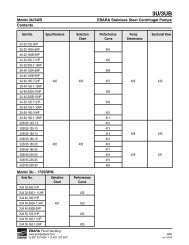
The StormTech SC-740 chamber shown in Figure 1<br />
on page 4 optimizes storage volumes in relatively small<br />
footprints. By providing 2.2 ft 3 /ft 2 (0.67 m 3 /m 2 ) [minimum]<br />
of storage, the SC-740 chambers can minimize excavation,<br />
backfill and associated costs.<br />
The StormTech SC-310 chamber shown in Figure 2 on<br />
page 4 is ideal for systems requiring low-rise and wide-span<br />
solutions. This low profile chamber allows the storage of<br />
large volumes, 1.3 ft 3 /ft 2 (0.40 m 3 /m 2 ) [minimum], at minimum<br />
depths. Product Specifications: 2.2 and 2.5<br />
Call StormTech at 888.892.2694 or visit our website at www.stormtech.com for technical and product information. 3
2.0 Product Information<br />
Figure 1 – StormTech SC-740 Chamber (not to scale)<br />
Nominal Chamber Specifications<br />
Size (W x H x Installed L) 51.0" (1295 mm) x 30.0" (762 mm) x 85.4" (2169 mm)<br />
Chamber Storage 45.9 ft 3 (1.30 m 3 )<br />
Min. Installed Storage* 74.9 ft 3 (2.12 m 3 )<br />
Weight 74 lbs (33.6 kg)<br />
30.0"<br />
(762 mm)<br />
24" (600 mm) DIA. MAX<br />
16.0"<br />
(406 mm)<br />
51.0" (1295 mm)<br />
Figure 2 – StormTech SC-310 Chamber (not to scale)<br />
Nominal Chamber Specifications<br />
Size (W x H x Installed L) 34.0" (864 mm) x 16.0" (406 mm) x 85.4" (2169 mm)<br />
Chamber Storage 14.7 ft 3 (0.42 m 3 )<br />
Min. Installed Storage* 31.0 ft 3 (0.88 m 3 )<br />
Weight 37 lbs (16.8 kg)<br />
12" (300 mm)<br />
DIA. MAX<br />
34.0" (864 mm)<br />
90.7" (2304 mm)<br />
85.4" (2169 mm) INSTALLED<br />
90.7" (2304 mm)<br />
85.4" (2169 mm) INSTALLED<br />
*This assumes a minimum of 6" (152 mm) of stone below, above and between chamber rows and 40% stone porosity.<br />
ACCEPTS 4" (100 mm)<br />
SCH 40 PIPE FOR OPTIONAL<br />
INSPECTION PORT<br />
ACCEPTS 4" (100 mm)<br />
SCH 40 PIPE FOR OPTIONAL<br />
INSPECTION PORT<br />
4 Call StormTech at 860.529.8188 or 888.892.2694 or visit our website at www.stormtech.com for technical and product information.
2.0 Product Information<br />
2.5 STORMTECH CHAMBERS<br />
StormTech chamber systems have unique features to<br />
improve site optimization and reduce product waste.<br />
The SC-740 and SC-310 chambers can be cut at the<br />
job site in approximately 6.5" (165 mm) increments to<br />
shorten a chamber’s length. <strong>Design</strong>ing and constructing<br />
chamber rows around site obstacles is easily accomplished<br />
by including specific cutting instructions or a<br />
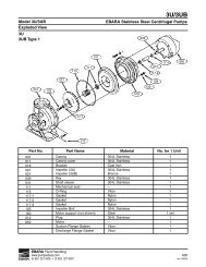
well placed “cut to fit” note on the design plans. The last<br />
chamber of a row can be cut in any of its corrugation’s<br />
valleys. An end cap placed into the trimmed corrugation’s<br />
crest completes the row. The trimmed-off piece of a<br />
StormTech chamber may then be used to start the next<br />
row. See Figure 3.<br />
To assist the contractor, StormTech chambers are<br />
molded with simple assembly instructions and arrows<br />
that indicate the direction in which to build rows. Rows<br />
are formed by overlapping the next chamber’s “Start<br />
End” corrugation with the previously laid chamber’s<br />
end corrugation. Two people can safely and efficiently<br />
form rows of chambers without complicated connectors,<br />
special tools or heavy equipment.<br />
Product Specifications: 2.2, 2.4, 2.9 and 3.2<br />
Figure 3 – Distance Between Corrugations (not to scale)<br />
CREST 14 PL<br />
5.8" (147 mm)<br />
VALLEY 13 PL<br />
6.5" (165 mm) 12 PL<br />
START END BUILD ROW IN THIS DIRECTION<br />
SC-740 chamber<br />
CREST 14 PL<br />
5.8" (147 mm)<br />
VALLEY 13 PL<br />
6.5" (165 mm) 12 PL<br />
START END BUILD ROW IN THIS DIRECTION<br />
SC-310 chamber<br />
OVERLAP NEXT<br />
CHAMBER HERE<br />
OVERLAP NEXT<br />
CHAMBER HERE<br />
2.6 STORMTECH END CAPS<br />
The StormTech end cap has features which make the<br />
chamber system simple to design, easy to build and<br />
more versatile than other products. StormTech end caps<br />
can be easily secured within any corrugation’s crest.<br />
A molded-in handle makes attaching the end cap a oneperson<br />
operation. Tools or fasteners are not required.<br />
StormTech end<br />
caps are required<br />
at each end of a<br />
chamber row to<br />
prevent stone<br />
intrusion (two per<br />
row). The SC-740<br />
end cap will<br />
accept up to a<br />
24" (600 mm)<br />
HDPE inlet pipe. The SC-310 end cap will accept up to<br />
a 12" (300 mm) HDPE inlet pipe. To aid con tractors, inlet<br />
pipe cutting guides and a blade-starting slot are molded<br />
into the end caps. See Figure 4.<br />
Product Specifications: 3.1, 3.2, 3.3 and 3.4<br />
Figure 4 – Chamber End Caps (not to scale)<br />
SC 740 CHAMBER FABRICATED END CAP (TOP AND BOTTOM FEED)<br />
PIPES SIZES RANGE FROM 6" (152 mm) TO 24" (600 mm)<br />
(INVERTS VARY WITH PIPE SIZE)<br />
SC-740 end cap<br />
SC 310 CHAMBER FABRICATED END CAP (TOP AND BOTTOM FEED)<br />
PIPES SIZES RANGE FROM 6" (152 mm) TO 12" (600 mm)<br />
(INVERTS VARY WITH PIPE SIZE)<br />
SC-310 end cap<br />
Call StormTech at 860.529.8188 or 888.892.2694 or visit our website at www.stormtech.com for technical and product information. 5
3.0 Structural Capabilities<br />
3.1 STRUCTURAL DESIGN APPROACH<br />
When installed per StormTech’s minimum requirements,<br />
StormTech products are designed to exceed American<br />
Association of State Highway and Transportation Officials<br />
(AASHTO) LRFD recommended design factors for Earth<br />
loads and Vehicular live loads. AASHTO Vehicular live<br />
loads (previously HS-20) consist of two heavy axle configurations,<br />
that of a single 32 (142 kN) kip axle and that of<br />
tandem 25 (111 kN) kip axles. Factors for impact and multiple<br />
presences of vehicles ensure a conservative design<br />
where structural adequacy is assumed for a wide range<br />
of street legal vehicle weights and axle configurations.<br />
Computer models of the chambers under shallow and<br />
deep conditions were developed. Utilizing design forces<br />
from computer models, chamber sections were evaluated<br />
using AASHTO procedures that consider thrust and<br />
moment, and check for local buckling capacity. The procedures<br />
also considered the time-dependent strength<br />
and stiffness properties of polypropylene. These procedures<br />
were developed in a research study conducted by<br />
the National Cooperative Highway Research Program<br />
(NCHRP) for AASHTO, and published as NCHRP Report<br />
438 Recommended LRFD Specifications for Plastic Pipe<br />
and Culverts. Product Specifications: 2.12.<br />
StormTech does not recommend installing StormTech<br />
products underneath buildings or parking garages. When<br />
specifying the StormTech products in close proximity to<br />
buildings, it is important to ensure that the StormTech<br />
products are not receiving any loads from these structures<br />
that may jeopardize the long term performance of the<br />
chambers.<br />
3.2 FULL SCALE TESTING<br />
After developing the StormTech chamber designs, the<br />
chambers were subjected to rigorous full-scale testing.<br />
The test programs verified the predicted safety factors<br />
of the designs by subjecting the chambers to more<br />
severe load conditions than anticipated during service<br />
life. Capacity under live loads and deep fill was investigated<br />
by conducting tests with a range of cover depths.<br />
Monitoring of long term deep fill installations has been<br />
done to validate the long term performance of the<br />
StormTech products.<br />
3.3 INDEPENDENT EXPERT ANALYSIS<br />
StormTech worked closely with the consulting firm Simpson<br />
Gumpertz & Heger Inc. (SGH) to develop and evaluate the<br />
SC-740 and SC-310 chamber designs. SGH has worldrenowned<br />
expertise in the design of buried drain age<br />
structures. The firm was the principal investigator for the<br />
NCHRP research program that developed the structural<br />
analysis and design methods recently adopted by AASHTO<br />
for thermoplastic culverts. SGH conducted design calculations<br />
and computer simulations of chamber performance<br />
under various installation and live load conditions. They<br />
worked with StormTech to design the full-scale test programs<br />
to verify the structural capacity of the chambers.<br />
SGH also observed all full-scale tests and inspected the<br />
chambers after completion of the tests. SGH continues to<br />
be StormTech’s structural consultant.<br />
6 Call StormTech at 888.892.2694 or visit our website at www.stormtech.com for technical and product information.
3.0 Structural Capabilities<br />
3.4 INJECTION MOLDING<br />
To comply with both the structural requirements of<br />
AASHTO’s LRFD design and analysis methods and<br />
product requirements of ASTM F2418 “Standard Specifi -<br />
cation for Polypropylene Corrugated Wall Stormwater<br />
Collection Chambers,” StormTech utilizes proprietary<br />
injection molding equipment to manufacture the SC-740<br />
and SC-310 chambers and end caps.<br />
In addition to meeting structural goals, injection molding<br />
allows StormTech to design added features and advantages<br />
into StormTech’s parts including:<br />
• Precise control of wall thickness throughout parts<br />
• Precise fit of joints and end caps<br />
• Molded-in inspection port fitting<br />
• Molded-in handles on end caps<br />
• Molded-in pipe guides with blade starter slots<br />
• Repeatability for Quality Control (See Section 3.6)<br />
Product Specifications: 2.1, 3.1 and 3.3<br />
3.5 POLYPROPYLENE RESIN<br />
StormTech chambers are injection molded from poly -<br />
pro pylene. Polypropylene chambers are inherently<br />
resistant to chemicals typically found in stormwater<br />
run-off. StormTech chambers maintain a greater portion<br />
of their structural stiffness through higher installation<br />
and service temperatures.<br />
StormTech polypropylene is a virgin material specially<br />
designed to achieve a high 50-year creep modulus that<br />
is necessary to provide a sound long-term structural<br />
design. Since the modulus remains high well beyond<br />
the 50-year value, StormTech chambers can exhibit a<br />
service life in excess of 50 years.<br />
3.6 QUALITY CONTROL<br />
StormTech SC-740 and SC-310 stormwater chambers<br />
are manufactured under tight quality control programs.<br />
Materials are routinely tested in an environmentally controlled<br />
lab that is verified every six months via the external<br />
ASTM Proficiency Testing Program. The chamber material<br />
properties are measured and controlled with procedures<br />
following ISO 9001:2000 requirements.<br />
Statistical Process Control (SPC) techniques are applied<br />
during manufacturing. Established upper and lower<br />
control limits are maintained on key manufacturing para -<br />
meters to maintain consistent product.<br />
Product Specifications: 2.13 and 3.6<br />
Call StormTech at 888.892.2694 or visit our website at www.stormtech.com for technical and product information. 7
4.0 Foundation for Chambers<br />
4.1 FOUNDATION REQUIREMENTS<br />
StormTech SC-740 and SC-310 chamber systems and<br />
embedment stone may be installed in various native soil<br />
types. The sub-grade bearing capacity and chamber cover<br />
height determine the required depth of clean, crushed,<br />
angular stone for the chamber foundation. The chamber<br />
foundation is the clean, crushed, angular stone placed<br />
between the subgrade soils and the feet of the chamber.<br />
As cover height increases (top of chamber to top of<br />
finished grade) the chambers foundation requirements<br />
increase. Foundation strength is the product of the subgrade<br />
soils bearing capacity and the depth of clean,<br />
crushed, angular stone below the chambers feet. Table 1<br />
specifies the required minimum foundation depth for<br />
varying cover heights and subgrade bearing capacities.<br />
The design engineer is responsible for assessing the bearing<br />
capacity of the sub-grade soil. Sub-grade soil conditions should<br />
be assessed with consideration of the range of soil moisture<br />
contents expected under a stormwater system.<br />
4.2 WEAKER SOILS<br />
For sub-grade soils with allowable bearing capacity less<br />
than 2000 pounds per square foot [(2.0 ksf) (96 kPa)],<br />
a geotech nical engineer should evaluate the specific<br />
conditions. These soils are often highly variable, may<br />
Table 1 – Minimum Required Foundation Depth in Inches (mm)<br />
contain organic materials and could be more sensitive to<br />
moisture. A geotechnical engineer’s recommendations<br />
may include increasing the stone foundation to greater<br />
than 18 inches (457 mm), improving the bearing<br />
capacity of the sub-grade soils through compaction,<br />
replacement, or other remedial measures including the<br />
use of geogrids. The use of a thermoplastic liner may<br />
also be considered for systems installed in subgrade<br />
soils that are highly affected by moisture. The project<br />
engineer is responsible for ensuring overall site settlement<br />
is within acceptable limits. A geotechnical engineer<br />
should always review installation of StormTech<br />
chambers on organic soils.<br />
4.3 CHAMBER SPACING OPTION<br />
StormTech always requires a minimum of 6" (152 mm)<br />
clear spacing between the feet of chambers rows. How -<br />
ever, increasing the spacing between chamber rows may<br />
allow the application of StormTech chambers with either<br />
less foundation stone or with weaker subgrade soils. This<br />
may be a good option where a vertical restriction on site<br />
prevents the use of a deeper foundation. Contact StormTech’s<br />
Technical Service Department for more information on this<br />
option. In all cases, StormTech recommends consulting<br />
a geotechnical engineer for subgrade soils with a bearing<br />
capacity less than 2.0 ksf (96 kPa).<br />
Cover Minimum Required Bearing Resistance for Service Loads ksf (kPa)<br />
Ht. ft. 4.1 4.0 3.9 3.8 3.7 3.6 3.5 3.4 3.3 3.2 3.1 3.0 2.9 2.8 2.7 2.6 2.5 2.4 2.3 2.2 2.1 2.0<br />
(m) (196) (192) (187) (182) (177) (172) (168) (163) (158) (153) (148) (144) (139) (134) (129) (124) (120) (115) (110) (105) (101) (96)<br />
1.5 6 6 6 6 6 6 6 6 6 6 6 6 9 9 9 9 9 12 12 12 15 15<br />
(0.46) (152) (152) (152) (152) (152) (152) (152) (152) (152) (152) (152) (152) (229) (229) (229) (229) (229) (305) (305) (305) (381) (381)<br />
2 6 6 6 6 6 6 6 6 6 6 6 9 9 9 9 9 12 12 12 15 15 15<br />
(0.61) (152) (152) (152) (152) (152) (152) (152) (152) (152) (152) (152) (229) (229) (229) (229) (229) (305) (305) (305) (381) (381) (381)<br />
2.5 6 6 6 6 6 6 6 6 6 6 9 9 9 9 9 12 12 12 15 15 15 18<br />
(0.76) (152) (152) (152) (152) (152) (152) (152) (152) (152) (152) (229) (229) (229) (229) (229) (305) (305) (305) (381) (381) (381) (457)<br />
3 6 6 6 6 6 6 6 6 6 9 9 9 9 9 12 12 12 15 15 15 18 18<br />
(0.91) (152) (152) (152) (152) (152) (152) (152) (152) (152) (229) (229) (229) (229) (229) (305) (305) (305) (381) (381) (381) (457) (457)<br />
3.5 6 6 6 6<br />
(1.07) (152) (152) (152) (152)<br />
6 6 6 6 9 9 9 9 9<br />
(152) (152) (152) (152) (229) (229) (229) (229) (229)<br />
12 12<br />
(305) (305)<br />
12 12 15 15 18 18 21<br />
(305) (305) (381) (381) (457) (457) (533)<br />
4 6 6 6 6 6 6 6 6 9 9 9 9 9 12 12 12 12 15 15 18 18 21<br />
(1.22) (152) (152) (152) (152) (152) (152) (152) (152) (229) (229) (229) (229) (229) (305) (305) (305) (305) (381) (381) (457) (457) (533)<br />
4.5 6 6 6 6 6 6 6 6 9 9 9 9 9 12 12 12 12 15 15 18 18 21<br />
(1.37) (152) (152) (152) (152) (152) (152) (152) (152) (229) (229) (229) (229) (229) (305) (305) (305) (305) (381) (381) (457) (457) (533)<br />
5 6 6 6 6 6 6 6 6 9 9 9 9 9 12 12 12 15 15 15 18 18 21<br />
(1.52) (152) (152) (152) (152) (152) (152) (152) (152) (229) (229) (229) (229) (229) (305) (305) (305) (381) (381) (381) (457) (457) (533)<br />
5.5 6 6 6 6 6 6 6 9 9 9 9 9 12 12 12 12 15 15 15 18 18 21<br />
(1.68) (152) (152) (152) (152) (152) (152) (152) (229) (229) (229) (229) (229) (305) (305) (305) (305) (381) (381) (381) (457) (457) (533)<br />
6 6 6 6 6 6 6 9 9 9 9 9 12 12 12 12 15 15 15 18 18 21 21<br />
(1.83) (152) (152) (152) (152) (152) (152) (229) (229) (229) (229) (229) (305) (305) (305) (305) (381) (381) (381) (457) (457) (533) (533)<br />
6.5 6 6 6 6 6 9 9 9 9 9 9 12 12 12 15 15 15 18 18 18 21 24<br />
(1.98) (152) (152) (152) (152) (152) (229) (229) (229) (229) (229) (229) (305) (305) (305) (381) (381) (381) (457) (457) (457) (533) (610)<br />
7 6 6 6 6<br />
(2.13) (152) (152) (152) (152)<br />
9 9 9 9 9 9 12 12 12<br />
(229) (229) (229) (229) (229) (229) (305) (305) (305)<br />
12 15<br />
(305) (381)<br />
15 15 18 18 21 21 24<br />
(381) (381) (457) (457) (533) (533) (610)<br />
7.5 6 6 6 9 9 9 9 9 12 12 12 12 12 15 15 15 18 18 21 21 24 27<br />
(2.29) (152) (152) (152) (229) (229) (229) (229) (229) (305) (305) (305) (305) (305) (381) (381) (381) (457) (457) (533) (533) (610) (686)<br />
8 6 9 9 9 9 9 9 12 12 12 12 12 15 15 15 18 18 21 21 24 24 27<br />
(2.44) (152) (229) (229) (229) (229) (229) (229) (305) (305) (305) (305) (305) (381) (381) (381) (457) (457) (533) (533) (610) (610) (686)<br />
NOTE: The design engineer is solely responsible for assessing the bearing resistance (allowable bearing capacity) of the subgrade<br />
soils and determining the depth of foundation stone. Subgrade bearing resistance should be assessed with consideration<br />
for the range of soil moisture conditions expected under a stormwater system.<br />
8 Call StormTech at 860.529.8188 or 888.892.2694 or visit our website at www.stormtech.com for technical and product information.
5.0 Required Materials/Row Separation<br />
5.1 CHAMBER ROW SEPARATION<br />
StormTech SC-740 and SC-310 chambers must be specified<br />
with a minimum 6" (152 mm) space between the<br />
feet of adjacent parallel chamber rows. Increasing<br />
the space between rows is acceptable. This will increase<br />
the storage volume due to additional stone voids.<br />
5.2 STONE SURROUNDING CHAMBERS<br />
Refer to Table 2 for acceptable stone materials. StormTech<br />
requires clean, crushed, angular stone below, between and<br />
6" (152 mm) above chambers as shown in Figure 5.<br />
Accept able gradations are listed in Table 2. Subrounded<br />
and rounded stone are not acceptable.<br />
5.3 GEOTEXTILE SEPARATION REQUIREMENT<br />
A non-woven geotextile that meets AASHTO M288 Class 2<br />
Separation requirements must be applied as a separation<br />
layer to prevent soil intrusion into the clean, crushed,<br />
Table 2 – Acceptable Fill Materials<br />
Material Location Description AASHTO M43 Compaction/Density<br />
<strong>Design</strong>ation 1 Requirement<br />
angular stone as shown in Figure 5. The geotextile is<br />
required between the clean, crushed, angular stone and<br />
the subgrade soils, the excavation’s sidewalls and the fill<br />
materials. The geotextile should completely envelope the<br />
clean, crushed, angular stone. Overlap adjacent geotextile<br />
rolls per AASHTO M288 separation guidelines. See<br />
Table 4 for a list of acceptable geotextiles.<br />
5.4 FILL ABOVE CHAMBERS<br />
Refer to Table 2 and Figure 5 for acceptable fill material<br />
above the 6" (152 mm) of clean, crushed, angular stone.<br />
StormTech requires a minimum of 18" (457 mm) and a<br />
maximum of 96" (2438 mm) of fill material [including the<br />
6" (152 mm) of stone above chambers]. StormTech<br />
requires a minimum of 24" (610 mm) of fill in non-paved<br />
installations where rutting from vehicles may occur.<br />
Table 2 provides details on soil class and compaction<br />
requirements for suitable fill materials.<br />
D Fill Material for layer D starts from Any soil/rock materials, native N/A Prepare per engineer’s plans. Installlations may have<br />
the top of the C layer to the bottom of soils or per engineer’s plans. stringent material and preparation requirements.<br />
flexible pavement or unpaved finished Check plans for pavement<br />
grade above. Note that pavement subbase<br />
may be part of the D layer.<br />
subgrade requirements.<br />
C Fill Material for layer C starts Granular well-graded soil/ 3, 357, 4, 467, Begin compaction after 12" (305 mm) of material over the<br />
from the top of the embedment stone aggregate mixtures,
6.0 Inletting the Chambers<br />
The design flexibility of a Stormtech chamber system<br />
includes many inletting possibilities. Contact StormTech’s<br />
Technical Service Department for guidance on designing<br />
an inlet system to meet specific site goals.<br />
6.1 TREATMENT TRAIN<br />
A properly designed inlet system can ensure good water<br />
quality, easy inspection and maintenance, and a long system<br />
service life. StormTech recommends a treatment train<br />
approach for inletting an underground stormwater management<br />
system under a typical commercial parking area.<br />
Treatment train is an industry term for a multi-tiered water<br />
quality network. As shown in Figure 6, a StormTech recommended<br />
inlet system can inexpensively have up to 3<br />
tiers of treatment upstream of the StormTech chambers:<br />
Tier 1 – Pre-treatment (BMP)<br />
Tier 2 - StormTech Isolator Row<br />
Tier 3 - Eccentric Pipe Manifold<br />
Figure 6 – Typical StormTech Treatment Train Inlet System<br />
6.2 PRE-TREATMENT (BMP) – TREATMENT TIER 1<br />
In some areas pre-treatment of the stormwater is<br />
required prior to entry into a stormwater system. By<br />
treating the stormwater prior to entry into the system, the<br />
service life of the system can be extended, pollutants<br />
such as hydrocarbons may be captured, and local regulations<br />
met. Pre-treatment options are often described<br />
as a Best Management Practice or simply a BMP.<br />
Pre-treatment devices differ greatly in complexity, design<br />
and effectiveness. Depending on a site’s characteristics<br />
and treatment goals, the simple, least expensive pretreatment<br />
solutions can sometimes be just as effective<br />
as the complex systems. Options include a simple<br />
deep sumped manhole with a 90° bend on its outlet,<br />
baffle boxes, swirl concentrators, sophisticated filtration<br />
devices, and devices that combine these processes.<br />
Some of the most effective pre-treatment options combine<br />
engineered site grading with vegetation such as<br />
bio-swales or grassy strips.<br />
The type of pretreatment device specified as the first<br />
level of treatment up-stream of a StormTech chamber<br />
system can vary greatly throughout the country and<br />
from site-to-site. It is the responsibility of the design<br />
engineer to understand the water quality issues and<br />
design a stormwater treatment system that will satisfy<br />
local regulators and follow applicable laws. A design<br />
engineer should apply their understanding of local<br />
weather conditions, site topography, local maintenance<br />
requirements, expected service life, etc…to select an<br />
appropriate stormwater pre-treatment system.<br />
6.3 STORMTECH ISOLATOR TM ROW – TREATMENT TIER 2<br />
StormTech has a patented technique to inexpensively<br />
enhance Total Suspended Solids (TSS) removal and provide<br />
easy access for inspection and maintenance. The<br />
StormTech Isolator Row is a row of standard StormTech<br />
chambers surrounded with appropriate filter fabrics and<br />
connected to a manhole for easy access. This application<br />
basically creates a filter/detention basin that allows<br />
water to egress through the surrounding filter fabric while<br />
sediment is trapped within. It may be best to think of the<br />
Isolator Row as a first-flush treatment device. First-Flush<br />
is a term typically used to describe the first 1⁄2" to 1" (13-25<br />
mm) of rainfall or runoff on a site. The majority of stormwater<br />
pollutants are carried in the sediments of the firstflush,<br />
therefore the Isolator Row is an effective component<br />
of a treatment train.<br />
The StormTech Isolator Row should be designed with a<br />
manhole with an overflow weir at its upstream end. The<br />
diversion manhole is multi-purposed. It can provide<br />
access to the Isolator Row for both inspection and maintenance<br />
and acts as a diversion structure. The manhole<br />
is connected to the Isolator Row with a short length of<br />
12” (300 mm) pipe for the SC-310 chamber and 24”<br />
(600 mm) pipe for the SC-740 chamber. These pipes<br />
are connected to the Isolator Row with a 12” (300 mm)<br />
fabricated end cap for the SC-310 chamber and a 24”<br />
(600 mm) fabricated end cap for the SC-740 chamber.<br />
The overflow weir typically has its crest set between the<br />
top of the chamber and its midpoint. This allows storm -<br />
water in excess of the Isolator Row’s storage/conveyance<br />
capacity to bypass into the chamber system through the<br />
downstream manifold system.<br />
Specifying and installing proper geotextiles is essential<br />
for efficient operation and to prevent damage to the<br />
system during the JetVac maintenance process. Two<br />
strips of woven geotextile that meets AASHTO M288<br />
Class 1 requirements is required between the chambers<br />
and their stone foundation. This strong filter fabric traps<br />
10 Call StormTech at 860.529.8188 or 888.892.2694 or visit our website at www.stormtech.com for technical and product information.
6.0 Inletting the Chambers<br />
Figure 7 – StormTech Isolator TM Row Detail<br />
CATCH<br />
BASIN<br />
OR<br />
MANHOLE<br />
SUMP<br />
DEPTH BY<br />
DESIGN<br />
ENGINEER<br />
SC-740 – 24'' (600 mm) PIPE<br />
SC-310 – 12'' (300 mm) PIPE<br />
INSPECTION PORT<br />
LOCATION PER ENGINEER'S<br />
DRAWING<br />
sediments and protects the stone base during maintenance.<br />
A strip of non-woven AASHTO M288 Class 2<br />
geotextile is draped over the Isolator chamber row. This<br />
6-8 oz. (217-278 g/m 2 ) non-woven filter fabric prevents<br />
sediments from migrating out of the chambers perforations<br />
while allowing modest amounts of water to flow out<br />
of the Isolator Row. Figure 7 is a detail of the Isolator<br />
Row that shows proper application of the geotextiles.<br />
Inspection is easily accomplished through the upstream<br />
manhole or optional inspection ports. Maintenance of an<br />
Isolator Row is fast and easy using the JetVac process<br />
through the upstream manhole. Section 13.0 explains the<br />
inspection and main tenance process in more detail.<br />
Each SC-740 chamber in an Isolator Row will store 45.9 ft 3<br />
(1.3 m 3 ) of first-flush stormwater. During and between<br />
storm events an Isolator Row will allow stormwater to<br />
egress at a rate of 0.25 cfs (7.1 l/s) or less per chamber.<br />
A bed of StormTech chambers may have multiple Isolator<br />
Rows to accommodate required first-flush volumes.<br />
6.4 ECCENTRIC MANIFOLD SYSTEM – TREATMENT TIER 3<br />
The third tier of the treatment train is the eccentric manifold<br />
system. This is much like a typical manifold system<br />
except that the inlet pipe stubs are smaller and located<br />
at a higher invert than the main trunk of the manifold.<br />
This is accomplished by building the manifold system<br />
with reducer tees installed upside down so a “sump” is<br />
created within the large dia meter header pipe as shown<br />
in Figure 8. A typical eccentric system might have a 48"<br />
(1200 mm) pipe with 18" (450 mm) manifolds creating a<br />
30" (750 mm) header sump.<br />
The upstream end of the eccentric manifold system will<br />
typically be connected directly to the downstream side of<br />
the Isolator Row’s weired manhole as shown in Figure 6.<br />
Pipe companies can provide more detailed information on<br />
designing a header system optimized for trapping TSS.<br />
COVER ENTIRE ROW WITH AASHTO M288<br />
CLASS 2 NON-WOVEN GEOTEXTILE<br />
SC-740 — 8' (2.4 m) WIDE STRIP<br />
SC-310 — 5' (1.5 m) WIDE STRIP<br />
2 LAYERS OF WOVEN GEOTEXTILE THAT MEETS AASHTO M288 CLASS 1<br />
REQUIREMENTS, BETWEEN STONE BASE AND CHAMBERS<br />
SC-740 — 5' (1.5 m) WIDE STRIP<br />
SC-310 — 4' (1.2 m) WIDE STRIP<br />
Figure 8 – Typical Eccentric Header System<br />
HEADER PIPE<br />
MANHOLE<br />
MANIFOLD PIPES<br />
STORMWATER<br />
CHAMBERS<br />
STORMTECH<br />
ENDCAP<br />
6.5 TREATMENT TRAIN CONCLUSION<br />
The treatment train is a highly effective water-quality<br />
approach that does not add significant cost to a StormTech<br />
system being installed under commercial parking areas.<br />
The StormTech Isolator Row adds a significant level<br />
of treatment, easy inspection and maintenance, while<br />
maintaining storage volume credit for the cost of a<br />
modest amount of geotextile. Finally, a pipe manifold<br />
system is a well recognized component of a chamber<br />
inlet system. Inverting the reducer tees creates an<br />
eccentric manifold system that can be easily inspected<br />
and maintained. This treatment train concept provides<br />
three levels of treatment, inspection and maintenance<br />
upstream of the StormTech detention/retention bed<br />
with little additional expense.<br />
6.6 OTHER INLET OPTIONS<br />
While the three-tiered treatment train approach is the<br />
recommended method of inletting StormTech chambers<br />
for typical under-commercial parking applications, there<br />
are other effective inlet methods that may be considered.<br />
For instance, Isolator Rows, while adding an inexpensive<br />
level of confidence, are not always necessary. A<br />
header system with fewer inlets can be designed to further<br />
minimize the cost of a StormTech system. There may<br />
be applications where stormwater pre-treatment may not<br />
be necessary at all and the system can be inlet directly<br />
from the source. Contact StormTech’s Technical Service<br />
Department to discuss inlet options.<br />
Call StormTech at 860.529.8188 or 888.892.2694 or visit our website at www.stormtech.com for technical and product information. 11
6.0 Inletting the Chambers<br />
6.7 LATERAL FLOW RATES<br />
The embedment stone surrounding the StormTech<br />
chambers allows the rapid conveyance of stormwater<br />
between chamber rows. Stormwater will rise and fall<br />
evenly within a bed of chambers. A single StormTech<br />
chamber is able to release or accept stormwater at a<br />
rate of at least 0.5 cfs (14.2 l/s) through the surrounding<br />
stone.<br />
6.8 INLETTING PERPENDICULAR TO A ROW OF CHAMBERS<br />
There is an easy, inexpensive method to perpendicularly<br />
inlet a row of chambers. Simply replace the chamber<br />
with a tee where the inlet pipe intersects the row. From<br />
the tee, short lengths of pipe may be used to penetrate<br />
the endcaps used to terminate the two new openings in<br />
the row. Figure 9 is a typical detail of the perpendicular<br />
inlet methods.<br />
Figure 9 – Perpendicular Inlet<br />
6.9 MAXIMUM INLET PIPE VELOCITIES TO PREVENT<br />
SCOURING OF THE STONE FOUNDATION<br />
This section is applicable to the classic manifold and<br />
emergency overflow inlet piping. Isolator Rows are protected<br />
from scouring by the woven geotextile.<br />
To prevent scouring of the foundation stone, inlet pipe<br />
flow velocities must not exceed those listed in Table 3.<br />
Flow velocities greater than those listed may cause<br />
excess scouring at the inlet water’s impact zone, which<br />
can be detrimental to the stone’s performance as a<br />
structural foundation. In these cases, scour control<br />
measures must be implemented. Simple scour control<br />
measures include applying rip-rap, geotextile material or<br />
splash dissipators to the inlet water’s projected impact<br />
zone. Many designers implement scour control measures<br />
as a general practice, regardless of flow velocity.<br />
StormTech recommends 12.5' (3.8 m) of AASHTO M288<br />
Class 1 woven geotextile at each inlet row.<br />
Table 3 – Maximum Inlet Velocity in Feet Per Second to Prevent<br />
Scouring of an Unprotected 3/4" to 2" (19 mm to 50 mm) Angular<br />
Stone Foundation<br />
Inlet Pipe Diameter Maximum Inlet Pipe Velocities<br />
in. (mm) feet per second (meters per second)<br />
4 (100) 2.43 (0.74)<br />
6 (150) 2.61 (0.80)<br />
8 (200) 2.73 (0.83)<br />
10 (250) 2.44 (0.74)<br />
12 (300) 2.19 (0.67)<br />
15 (375) 2.00 (0.61)<br />
18 (450) 1.88 (0.57)<br />
24 (600) 1.74 (0.53)<br />
Table 4 – Some Suitable Geotextiles<br />
Manufacturer AASHTO M288 AASHTO M288<br />
Class 2<br />
Non-Woven*<br />
Class 1 Woven**<br />
Belton Industries — Beltech 977<br />
Carthage Mills FX-60HS, FX-80HS FX-66<br />
Contech Const. Products NW6, NW8 —<br />
GSE Lining Technology —<br />
Maccaferri MacTex MX245<br />
MacTex MX275<br />
—<br />
Pavco - Amanco NT 3000, NT 4000 TR 4000<br />
Propex Geotex 651 Geotext 315ST<br />
Geotex 861 Geotex 2X2HF<br />
Geotex 601<br />
Geotex 701<br />
Geotex 801<br />
Geotex 250ST<br />
SKAPS Industries GT 160NW<br />
GT 180NW<br />
W315<br />
Tencate Mirafi Mirafi 160N Mirafi 600X<br />
Mirafi 180N Filterweave 403<br />
Filterweave 404<br />
Geolon HP570<br />
Geolon HP665<br />
Geolon HP770<br />
TNS Advanced Tech. R 060, R070<br />
R 080, R100<br />
—<br />
US Fabrics US 205NW-C,<br />
US160NW<br />
US 315<br />
*AASHTO M288 Class 2 Non-Woven Geotextile Application: 1. Separation layer<br />
between angular stone cover and fill to prevent fines intrusion. 2. Filter layer over<br />
the chambers of the Stormtech Isolator Row to prevent fines migration out of<br />
row while maintaining adequate hydraulic flows.<br />
**AASHTO M288 Class 1 Woven Geotextile Application: 1. Stabilization layer for<br />
the angular stone foundation of the StormTech Isolator Row to prevent scouring<br />
of the foundation stone during the JetVac maintenance procedure, modest hydraulic<br />
flows maintained. 2. At each inlet row to prevent scouring of the foundation stone.<br />
12 Call StormTech at 860.529.8188 or 888.892.2694 or visit our website at www.stormtech.com for technical and product information.
7.0 Outlets for Chambers<br />
7.0 OUTLETS FOR STORMTECH CHAMBER SYSTEMS<br />
The majority of StormTech installations are detention<br />
systems and have some type of outlet structure. An outlet<br />
manifold is generally designed to ensure that peak flows<br />
can be conveyed to the outlet structure.<br />
To drain the system completely, an underdrain system is<br />
located at or below the bottom of the foundation stone.<br />
Although it’s not usually necessary, some beds may be<br />
designed with a pitched base to ensure complete<br />
drainage of the system. A grade of 1⁄2% is usually satisfactory.<br />
An outlet pipe may be located at a higher invert within a<br />
bed. This allows a designed volume of water to infiltrate<br />
while excess volumes are outlet as necessary. This is an<br />
excellent method of recharging groundwater, replicating<br />
a site’s pre-construction hydraulics.<br />
Depending on the bed layout and inverts, outlet pipes<br />
should be placed in the embedment stone along the<br />
bed’s perimeter as shown in Figures 10 and 11. Solid outlet<br />
pipes may also be used to penetrate the StormTech end<br />
caps at the designed outlet invert as shown in Figure 12.<br />
An Isolator Row should not be directly penetrated with<br />
an outlet pipe. For systems requiring higher outlet flow<br />
rates, a combination of connections may be utilized as<br />
shown in Figure 13.<br />
In detention and retention applications the discharge<br />
of water from the stormwater management system is<br />
determined based on the hydrology of the area and the<br />
hydraulic design of the system. It is the design engineer’s<br />
responsibility to design an outlet system that meets<br />
their hydraulic objectives while following local laws and<br />
regulations.<br />
Figure 10 – Underdrain Parallel<br />
BED PERIMETER<br />
BED PERIMETER<br />
SECTION A_A<br />
PERFOR ATED<br />
UNDERDRAIN PIPE<br />
TO OUTLET<br />
CONTROL<br />
STRUCTURE<br />
STORMTECH<br />
CHAMBER<br />
STONE BASE<br />
BENEATH<br />
CHAMBER<br />
AASHTO M288<br />
CLASS 2 NON-WOVEN<br />
GEOTEXTILE<br />
STONE BEDDING<br />
UNDER DRAINAGE<br />
PIPE (PER DESIGN)<br />
Call StormTech at 860.529.8188 or 888.892.2694 or visit our website at www.stormtech.com for technical and product information. 13<br />
A<br />
A<br />
Figure 11 – Underdrain Perpendicular<br />
B B<br />
Figure 12 – Outlet Manifold<br />
BED PERIMETER<br />
ISOLATOR ROW<br />
C C<br />
STORMTECH<br />
CHAMBER<br />
STONE BASE<br />
BENEATH<br />
CHAMBER<br />
AASHTO M288<br />
CLASS 2 NON-WOVEN<br />
GEOTEXTILE<br />
TO OUTLET CONTROL<br />
STRUCTURE<br />
STORMTECH<br />
CHAMBER<br />
STONE<br />
BASE<br />
BENEATH<br />
CHAMBER<br />
TO OUTLET CONTROL<br />
STRUCTURE<br />
Figure 13 – Combination Outlet<br />
NUMBER AND SIZE OF UNDER-<br />
DRAINS PER ENGINEER DESIGN<br />
BED PERIMETER<br />
OUTLET CONTROL STRUCTURE<br />
PER ENIGNEER'S DESIGN<br />
B<br />
A<br />
B<br />
A<br />
STORMTECH<br />
CHAMBER<br />
FOUNDATION<br />
STONE BENEATH<br />
CHAMBER<br />
STORMTECH<br />
CHAMBER<br />
FOUNDATION<br />
STONE<br />
BENEATH<br />
CHAMBER<br />
STONE BEDDING<br />
UNDER DRAINAGE<br />
PIPE (PER DESIGN)<br />
SECTION B_B<br />
SECTION C_C<br />
SECTION B_B<br />
PERFORATED<br />
UNDERDRAIN PIPE<br />
STONE BEDDING<br />
UNDER DRAINAGE<br />
PIPE (PER DESIGN)<br />
SECTION A_A<br />
MANIFOLD<br />
OUTLET<br />
PIPING<br />
OUTLET<br />
CONTROL<br />
STRUCTURE<br />
AASHTO M288<br />
CLASS 2<br />
NON-WOVEN<br />
GEOTEXTILE<br />
PERFORATED<br />
UNDERDRAIN PIPE<br />
AASHTO M288<br />
CLASS 2<br />
NON-WOVEN<br />
GEOTEXTILE
8.0 Cumulative Storage Volumes<br />
Table 5 and Table 6 provide cumulative storage volumes<br />
for SC-310 and SC-740 chamber systems. This infor -<br />
ma tion may be used to calculate a detention/retention<br />
system’s stage storage volume. A spreadsheet is available<br />
at www.stormtech.com in which the number of<br />
chambers can be input for quick cumulative storage<br />
calculations<br />
Product Specifications: 1.1, 2.2, 2.3, 2.4 and 2.6<br />
TABLE 5 – SC-310 Cumulative Storage Volumes Per Chamber<br />
Assumes 40% Stone Porosity. Calculations are Based<br />
Upon a 6" (152 mm) Stone Base Under the Chambers.<br />
Depth of Water Cumulative Total System<br />
in System Chamber Storage Cumulative Storage<br />
Inches (mm) ft 3 (m 3 ) ft 3 (m 3 )<br />
28 (711) 14.70 (0.416) 31.00 (0.878)<br />
27 (686) 14.70 (0.416) 30.21 (0.855)<br />
26 (680) Stone 14.70 (0.416) 29.42 (0.833)<br />
25 (610) Cover 14.70 (0.416) 28.63 (0.811)<br />
24 (609) 14.70 (0.416) 27.84 (0.788)<br />
23 (584) 14.70 (0.416) 27.05 (0.766)<br />
22 (559) 14.70 (0.416) 26.26 (0.748)<br />
21 (533) 14.64 (0.415) 25.43 (0.720)<br />
20 (508) 14.49 (0.410) 24.54 (0.695)<br />
19 (483) 14.22 (0.403) 23.58 (0.668)<br />
18 (457) 13.68 (0.387) 22.47 (0.636)<br />
17 (432) 12.99 (0.368) 21.25 (0.602)<br />
16 (406) 12.17 (0.345) 19.97 (0.566)<br />
15 (381) 11.25 (0.319) 18.62 (0.528)<br />
14 (356) 10.23 (0.290) 17.22 (0.488)<br />
13 (330) 9.15 (0.260) 15.78 (0.447)<br />
12 (305) 7.99 (0.227) 14.29 (0.425)<br />
11 (279) 6.78 (0.192) 12.77 (0.362)<br />
10 (254) 5.51 (0.156) 11.22 (0.318)<br />
9 (229) 4.19 (0.119) 9.64 (0.278)<br />
8 (203) 2.83 (0.081) 8.03 (0.227)<br />
7 (178) 1.43 (0.041) 6.40 (0.181)<br />
6 (152) 0 4.74 (0.134)<br />
5 (127) 0 3.95 (0.112)<br />
4 (102) Stone 0 3.16 (0.090)<br />
3 (76) Foundation 0 2.37 (0.067)<br />
2 (51) 0 1.58 (0.046)<br />
1 (25) 0 0.79 (0.022)<br />
Note: Add 0.79 ft 3 (0.022 m 3 ) of storage for each additional<br />
inch (25 mm) of stone foundation.<br />
TABLE 6 – SC-740 Cumulative Storage Volumes Per Chamber<br />
Assumes 40% Stone Porosity. Calculations are Based<br />
Upon a 6" (152 mm) Stone Base Under the Chambers.<br />
Depth of Water Cumulative Total System<br />
in System Chamber Storage Cumulative Storage<br />
Inches (mm) Ft 3 (m 3 ) Ft 3 (m 3 )<br />
42 (1067) 45.90 (1.300) 74.90 (2.121)<br />
41 (1041) 45.90 (1.300) 73.77 (2.089)<br />
40 (1016) Stone 45.90 (1.300) 72.64 (2.057)<br />
39 (991) Cover 45.90 (1.300) 71.52 (2.025)<br />
38 (965) 45.90 (1.300) 70.39 (1.993)<br />
37 (948) 45.90 (1.300) 69.26 (1.961)<br />
36 (914) 45.90 (1.300) 68.14 (1.929)<br />
35 (889) 45.85 (1.298) 66.98 (1.897)<br />
34 (864) 45.69 (1.294) 65.75 (1.862)<br />
33 (838) 45.41 (1.286) 64.46 (1.825)<br />
32 (813) 44.81 (1.269) 62.97 (1.783)<br />
31 (787) 44.01 (1.246) 61.36 (1.737)<br />
30 (762) 43.06 (1.219) 59.66 (1.689)<br />
29 (737) 41.98 (1.189) 57.89 (1.639)<br />
28 (711) 40.80 (1.155) 56.05 (1.587)<br />
27 (686) 39.54 (1.120) 54.17 (1.534)<br />
26 (660) 38.18 (1.081) 52.23 (1.479)<br />
25 (635) 36.74 (1.040) 50.23 (1.422)<br />
24 (610) 35.22 (0.977) 48.19 (1.365)<br />
23 (584) 33.64 (0.953) 46.11 (1.306)<br />
22 (559) 31.99 (0.906) 44.00 (1.246)<br />
21 (533) 30.29 (0.858) 41.85 (1.185)<br />
20 (508) 28.54 (0.808) 39.67 (1.123)<br />
19 (483) 26.74 (0.757) 37.47 (1.061)<br />
18 (457) 24.89 (0.705) 35.23 (0.997)<br />
17 (432) 23.00 (0.651) 32.96 (0.939)<br />
16 (406) 21.06 (0.596) 30.68 (0.869)<br />
15 (381) 19.09 (0.541) 28.36 (0.803)<br />
14 (356) 17.08 (0.484) 26.03 (0.737)<br />
13 (330) 15.04 (0.426) 23.68 (0.670)<br />
12 (305) 12.97 (0.367) 21.31 (0.608)<br />
11 (279) 10.87 (0.309) 18.92 (0.535)<br />
10 (254) 8.74 (0.247) 16.51 (0.468)<br />
9 (229) 6.58 (0.186) 14.09 (0.399)<br />
8 (203) 4.41 (0.125) 11.66 (0.330)<br />
7 (178) 2.21 (0.063) 9.21 (0.264)<br />
6 (152) 0 6.76 (0.191)<br />
5 (127) 0 5.63 (0.160)<br />
4 (102) Stone 0 4.51 (0.125)<br />
3 (76) Foundation 0 3.38 (0.095)<br />
2 (51) 0 2.25 (0.064)<br />
1 (25) 0 1.13 (0.032)<br />
Note: Add 1.13 ft 3 (0.032 m 3 ) of storage for each additional<br />
inch (25 mm) of stone foundation.<br />
14 Call StormTech at 860.529.8188 or 888.892.2694 or visit our website at www.stormtech.com for technical and product information.
9.0 Other Considerations<br />
9.1 EROSION CONTROL<br />
Erosion and sediment control measures must be integrated<br />
into the plan to protect the stormwater system both during<br />
and after construction. These practices may have a direct<br />
impact on the system’s infiltration performance and<br />
longevity. Vegetation, temporary sediment barriers (silt<br />
fences, hay bales, fabric-wrapped catch basin grates),<br />
and strategic storm water runoff management may be<br />
used to control erosion and sedimentation. StormTech<br />
recommends the use of pipe plugs on the inlet pipe until<br />
the system is in service.<br />
9.2 SITE IMPROVEMENT TECHNIQUES<br />
When site conditions are less than optimal, StormTech<br />
recognizes many methods for improving a site for con -<br />
struc tion. Some techniques include the removal and<br />
replacement of poor materials, the use of engineered<br />
subgrade materials, aggregates, chemical treatment,<br />
and mechanical treatments including the use of geo -<br />
syn thetics. StormTech recommends referring to AASHTO<br />
M-288 guidelines for the appropriate use of geotextiles.<br />
StormTech also recognizes geogrid as a potential component<br />
of an engineered solution to improve site conditions<br />
or as a construction tool for the experienced contractor.<br />
StormTech chamber systems are compatible with the<br />
use of geosynthetics. The use of geosynthetics or any<br />
other site improvement method does not eliminate or<br />
modify any of StormTech’s requirements. It is the ultimate<br />
responsibility of the design engineer to ensure<br />
that site conditions are suitable for a StormTech<br />
chamber system.<br />
9.3 CONFORMING TO SITE CONSTRAINTS<br />
StormTech chambers have the unique ability to conform to<br />
site constraints such as utility lines, light posts, large trees,<br />
etc. Rows of chambers can be ended short or interrupted<br />
by placing an end cap at the desired location, leaving the<br />
required number of chambers out of the row to get by<br />
the obstruction, then starting the row of chambers again<br />
with another end cap. See Figure 14 for an example.<br />
Figure 14 – Ability to Conform to Site Constraints<br />
9.4 LINERS<br />
StormTech chambers offer the distinct advantage and<br />
versatility that allow them to be designed as an open<br />
bottom detention or retention system. In fact, the vast<br />
majority of StormTech installations and designs are open<br />
bottom detention systems. Using an open bottom system<br />
enables treatment of the storm water through the underlying<br />
soils and provides a volume safety factor based on<br />
the infiltrative capacity of the underlying soils.<br />
In some applications, however, open bottom detention<br />
systems may not be allowed. StormTech’s Tech Sheet #2<br />
provides guidance for the design and installation of thermoplastic<br />
liners for detention systems using StormTech<br />
chambers. The major points of the memo are:<br />
• Infiltration of stormwater is generally a desirable<br />
stormwater management practice, often required by<br />
regulations. Lined systems should only be specified<br />
where unique site conditions preclude significant<br />
infiltration.<br />
• Thermoplastic liners provide cost effective and viable<br />
means to contain stormwater in StormTech subsurface<br />
systems where infiltration is undesirable.<br />
• PVC and LLDPE are the most cost effective, installed<br />
membrane materials.<br />
• Enhanced puncture resistance from angular aggregate<br />
on the water side and from protrusions on the soil side<br />
can be achieved by placing a non-woven geotextile<br />
reinforcement on each side of the geomembrane. A<br />
sand underlayment in lieu of the geotextile reinforcement<br />
on the soil side may be considered when cost<br />
effective.<br />
• StormTech does not design, fabricate, sell or install<br />
thermoplastic liners. StormTech recommends consulting<br />
with liner professionals for final design and<br />
installation advice.<br />
Figure 15 – Chamber bed placed around light post.<br />
Call StormTech at 860.529.8188 or 888.892.2694 or visit our website at www.stormtech.com for technical and product information. 15
10.0 System Sizing<br />
For quick calculations, refer to the Site Calculator on<br />
StormTech’s website at www.stormtech.com.<br />
10.1 SYSTEM SIZING<br />
The following steps provide the calculations necessary to<br />
size a system. The worksheet on page 17 itemizes these<br />
calculations and costs. If you need assistance determining<br />
the number of chambers per row or customizing the<br />
bed configuration to fit a specific site, call StormTech’s<br />
Technical Services Department at 1-888-892-2694.<br />
1) Determine the amount of storage volume (V S )<br />
required.<br />
It is the design engineer’s sole responsibility to determine<br />
the storage volume required by local codes.<br />
TABLE 7 – Storage Volume Per Chamber<br />
Bare Chamber and Stone<br />
Chamber Foundation Depth<br />
Storage in. (mm)<br />
ft<br />
Note: Storage volumes are in cubic feet per chamber. Assumes 40%<br />
porosity for the stone plus the chamber volume.<br />
3 (m3 ) 6 (152) 12 (305) 18 (457)<br />
StormTech SC-740 45.9 (1.3) 74.9 (2.1) 81.7 (2.3) 88.4 (2.5)<br />
StormTech SC-310 14.7 (0.4) 31.0 (0.9) 35.7 (1.0) 40.4 (1.1)<br />
2) Determine the number of chambers (C) required.<br />
To calculate the number of chambers needed for<br />
adequate storage, divide the storage volume (Vs)<br />
by the volume of the selected chamber, as follows:<br />
C = Vs / Volume per Chamber<br />
3) Determine the required bed size (S).<br />
To find the size of the bed, multiply the number<br />
of chambers needed (C) by either:<br />
StormTech SC-740<br />
bed area per chamber = 33.8 ft2 (3.1 m3 )<br />
StormTech SC-310<br />
bed area per chamber = 23.7 ft2 (2.2 m3 )<br />
S = (C x bed area per chamber) +<br />
[1 foot (0.3 m) x bed perimeter in feet (meters)]<br />
NOTE: It is necessary to add one foot (0.3 m) around the perimeter<br />
of the bed for end caps and working space.<br />
4) Determine the amount of clean, crushed, angular<br />
stone (Vst) required.<br />
TABLE 8 – Amount of Stone Per Chamber in Tons (kg)<br />
Stone Foundation Depth<br />
ENGLISH 6" 12" 18"<br />
StormTech SC-740 3.8 (2.8 yd<br />
Note: Assumes 6" (152 mm) of stone above, and between chambers.<br />
3 ) 4.6 (3.3 yd3 ) 5.5 (3.9 yd3 )<br />
StormTech SC-310 2.1 (1.5 yd3 ) 2.7 (1.9 yd3 ) 3.4 (2.4 yd3 )<br />
METRIC 152 mm 305 mm 457 mm<br />
StormTech SC-740 3450 (2.1 m3 ) 4170 (2.5 m3 ) 4490 (3.0 m3 )<br />
StormTech SC-310 1830 (1.1 m3 ) 2490 (1.5 m3 ) 2990 (1.8 m3 )<br />
To calculate the total amount of clean, crushed, angular<br />
stone required, multiply the number of chambers (c) by<br />
the selected weight of stone from Table 8.<br />
NOTE: Clean, crushed, angular stone is also required around the<br />
perimeter of the system.<br />
5) Determine the volume of excavation (Ex) required.<br />
6) Determine the area of filter fabric (F) required.<br />
TABLE 9 – Volume of Excavation Per Chamber<br />
Stone Foundation Depth<br />
6" (152 mm) 12" (305 mm) 18" (457 mm)<br />
StormTech SC-740 5.5 (4.2) 6.2 (4.7) 6.8 (5.2)<br />
StormTech SC-310 2.9 (2.2) 3.4 (2.6) 3.8 (2.9)<br />
Note: Volumes are in cubic yards (cubic meters) per chamber.<br />
Assumes 6" (152 mm) of separation between chamber rows and 18"<br />
(457 mm) of cover. The volume of excavation will vary as the depth<br />
of the cover increases.<br />
Each additional foot of cover will add a volume of excavation of<br />
1.3 yds 3 (1.0 m 3 ) per SC-740 and 0.9 yds 3 (0.7 m 3 ) per SC-310<br />
chamber.<br />
The bottom and sides of the bed and the top of the<br />
embedment stone must be covered with a non-woven<br />
geotextile (filter fabric) that meets AASHTO M288 Class<br />
2 requirement. The area of the sidewalls must be calculated<br />
and a 2 foot (0.6 m) overlap must be included<br />
where two pieces of filter fabric are placed side-by-side<br />
or end-to-end. Geotextiles typically come in 15 foot (4.6<br />
m) wide rolls.<br />
7) Determine the number of end caps (E C ) required.<br />
Each row of chambers requires two end caps.<br />
E C = number of rows x 2<br />
16 Call StormTech at 860.529.8188 or 888.892.2694 or visit our website at www.stormtech.com for technical and product information.
11.0 Materials Worksheet<br />
Project ____________________________________<br />
By ________________________________________<br />
SYSTEM COST<br />
Location __________________________________<br />
SYSTEM REQUIREMENTS STORMTECH SC-310 STORMTECH SC-740<br />
1. Required storage volume (V s ) V s ____ ft 3 (m 3 ) ____ ft 3 (m 3 )<br />
2. Number of chambers (C) required: C ____ (V s ) / chamber storage ____ (V s ) / chamber storage<br />
3. Required bed size (S): S ____ [(C) x 23.7 ft 2 ] + (1 ft. x bed perimeter) ____ [(C) x 33.8 ft 2 ] + (1 ft. x bed perimeter)<br />
____ [(C) x 2.2 m 2 ] + (0.3 m x bed perimeter) ____ [(C) x 3.1 m 2 ] + (0.3 m x bed perimeter)<br />
4. Tons of stone (V st ) required: V st ____ Number from Table 8 x (C) ____ Number from Table 8 x (C)<br />
5. Volume of excavation (E x ): E x ____ Number from Table 9 x (C) ____ Number from Table 9 x (C)<br />
6. Area of filter fabric (F) required = F ____ yd 2 (m 2 ) ____ yd 2 (m 2 )<br />
7. Quantity of end caps required<br />
[2 x number of rows (E c )]: E c ____ End caps ____ End caps<br />
Note: Round up to the nearest whole number.<br />
Quantity Cost Total<br />
Chambers (C) _______________ x $ ______________/Chamber = $ ________________________<br />
Stone (Tst ) _______________ x $ ______________/Tons (kg) = $ ________________________<br />
Excavation (Ex ) _______________ x $ ______________/yd3 (m3 ) = $ ________________________<br />
Filter fabric (F) _______________ x $ ______________/yd2 (m2 ) = $ ________________________<br />
End caps (Ec ) _______________ x $ ______________/End caps = $ ________________________<br />
SUBTOTAL* : $ ________________________<br />
COST PER FT 3 (m 3 ) (subtotal ÷ required storage (V s ): $ ________________________<br />
Refer to StormTech’s website www.stormtech.com for an interactive version of this worksheet.<br />
* Chamber costs may not be inclusive of shipping. For general estimate purposes only. Calculations do not reflect changes in geographical costs or<br />
contractor’s overhead, profit and other miscellaneous expenses.<br />
Call StormTech at 860.529.8188 or 888.892.2694 or visit our website at www.stormtech.com for technical and product information. 17
12.0 Detail Drawings<br />
Figure 16 – Plan View Detail – StormTech Chambers (not to scale)<br />
AASHTO M288 CLASS 2<br />
NON-WOVEN GEOTEXTILE<br />
STORMTECH CHAMBER<br />
STORMTECH END CAP<br />
Figure 17 – Typical Cross Section Detail – StormTech Chambers (not to scale)<br />
THE INSTALLED CHAMBER SYSTEM SHALL PROVIDE<br />
THE LOAD FACTORS SPECIFIED IN THE AASHTO LRFD<br />
BRIDGE DESIGN SPECIFICATIONS SECTION 12.12 FOR<br />
EARTH AND LIVE LOADS, WITH CONSIDERATION FOR<br />
IMPACT AND MULTIPLE VEHICLE PRESENCES.<br />
3/4-2" (19-51 mm) CLEAN, CRUSHED, ANGULAR STONE<br />
SC-740 CHAMBER<br />
AASHTO M288 CLASS 2<br />
NON-WOVEN GEOTEXTILE<br />
DESIGN ENGINEER IS RESPONSIBLE FOR<br />
ENSURING THE REQUIRED BEARING CAPACITY<br />
OF SUBGRADE SOILS*<br />
6" (152 mm) MIN.<br />
FOR UNPAVED INSTALLATION WHERE<br />
RUTTING FROM VEHICLES MAY OCCUR,<br />
INCREASE COVER TO 24" (610 MM)<br />
PAVEMEN T<br />
51" (1295 mm) MIN.<br />
PAVEMENT SUB-BASE<br />
COMPACTED FILL PER<br />
STORMTECH'S TABLE OF<br />
ACCEPTABLE FILL MATERIALS*<br />
AASHTO M288 CLASS 2<br />
NON-WOVEN GEOTEXTILE<br />
6" (152 mm) MIN. DEPTH OF<br />
3/4-2" (19-51 mm) CLEAN,<br />
CRUSHED, ANGULAR<br />
STONE BACKFILL<br />
3/4-2" (19-51 mm) CLEAN, CRUSHED<br />
ANGULAR STONE BENEATH AND<br />
AROUND CHAMBER BED. DEPTH TO<br />
BE DETERMINED BY DESIGN ENGINEER*<br />
CHAMBERS SHALL MEET ASTM F 2418-05 “STANDARD<br />
SPECIFICATION FOR POLYPROPYLENE (PP) CORRUGATED<br />
WALL STORMWATER COLLECTION CHAMBERS.”<br />
GRANULAR WELL GRADED SOIL/AGGREGATE<br />
MIXTURES,
12.0 Detail Drawings<br />
Figure 18 – Inlet and Outlet Detail – StormTech Non-Isolator Row (not to scale)<br />
SUMP<br />
Figure 19 – StormTech Isolator TM Row (not to scale)<br />
CATCH<br />
BASIN<br />
OR<br />
MANHOLE<br />
SUMP<br />
DEPTH BY<br />
DESIGN<br />
ENGINEER<br />
CATCH BASIN<br />
OR<br />
MANHOLE<br />
PAVEMENT<br />
DESIGN ENGINEER IS<br />
RESPONSIBLE FOR ENSURING<br />
THE REQUIRED BEARING CAPACITY<br />
OF SUBGRADE SOILS*<br />
*See Section 4 of this <strong>Design</strong> <strong>Manual</strong>.<br />
SC-740 – 24'' (600 mm) PIPE<br />
SC-310 – 12'' (300 mm) PIPE<br />
GRANULAR WELL GRADED SOIL / AGGREGATE MIXTURES,
12.0 Detail Drawings<br />
12.0 AVAILABLE DETAIL DRAWINGS<br />
Below are examples of some of the CAD and PDF drawings that are available at www.stormtech.com.<br />
MANHOLE WITH<br />
OVERFLOW WEIR<br />
ECCENTRIC<br />
HEADER<br />
TREATMENT<br />
TIER 3<br />
4" PVC RISER<br />
SC-740 CHAMBER<br />
Technical Specifications<br />
ISOLATOR ROW<br />
TREATMENT TIER 2<br />
LANDSAVER CHAMBERS<br />
Classic Manifold Detail<br />
FLOOR BOX FRAME AND LID W/S.S.<br />
CAP SCREW LID CLOSURE<br />
INSPECTION PORT WITH SCREW-IN CAP<br />
CLASS "C" CONCRETE<br />
AASHTO M288 CLASS 2<br />
NON-WOVEN GEOTEXTILE<br />
18"<br />
96"<br />
MIN.<br />
MAX.<br />
FOR STORMTECH PURCHASING<br />
INFORMATION CALL 1-888-892-2694<br />
STORMTECH SC-740 CHAMBER SYSTEM<br />
INSPECTION PORT DETAIL<br />
NOT TO SCALE<br />
Inspection Port Detail<br />
Isolator Profile View<br />
THE INSTALLED CHAMBER SYSTEM SHALL PROVIDE<br />
THE LOAD FACTORS SPECIFIED IN THE AASHTO LRFD<br />
BRIDGE DESIGN SPECIFICATIONS SECTION 12.12 FOR<br />
EARTH AND LIVE LOADS, WITH CONSIDERATION FOR<br />
IMPACT AND MULTIPLE VEHICLE PRESENCES.<br />
3/4-2" (19-51 mm) CLEAN, CRUSHED, ANGULAR STONE<br />
SC-740 CHAMBER<br />
AASHTO M288 CLASS 2<br />
NON-WOVEN GEOTEXTILE<br />
AASHTO M288 CLASS 2<br />
NON-WOVEN GEOTEXTILE<br />
STORMTECH SC-740 CHAMBER SYSTEM<br />
PLAN VIEW DETAIL<br />
NOT TO SCALE<br />
CHAMBERS SHALL MEET ASTM F 2418-05 “STANDARD<br />
SPECIFICATION FOR POLYPROPYLENE (PP) CORRUGATED<br />
WALL STORMWATER COLLECTION CHAMBERS.”<br />
GRANULAR WELL GRADED SOIL/AGGREGATE<br />
MIXTURES,
13.0 Inspection and Maintenance<br />
13.1 ISOLATOR ROW INSPECTION<br />
Regular inspection and maintenance are essential to assure<br />
a properly functioning stormwater system. Inspec tion is<br />
easily accomplished through the manhole or optional<br />
inspection ports of an Isolator Row. Please follow local<br />
and OSHA rules for a confined space entry.<br />
Inspection ports can allow inspection to be accomplished<br />
completely from the surface without the need for a confined<br />
space entry. Inspection ports provide visual access<br />
to the system with the use of a flashlight. A stadia rod<br />
may be inserted to determine the depth of sediment.<br />
If upon visual inspection it is found that sediment has<br />
accumulated to an average depth exceeding 3" (76 mm),<br />
cleanout is required.<br />
A StormTech Isolator Row should initially be inspected<br />
immediately after completion of the site’s construction.<br />
While every effort should be made to prevent sediment<br />
from entering the system during construction, it is during<br />
this time that excess amounts of sediments are most<br />
likely to enter any stormwater system. Inspection and<br />
maintenance, if necessary, should be performed prior<br />
to passing responsibility over to the site’s owner. Once<br />
in normal service, a StormTech Isolator Row should be<br />
inspected bi-annually until an understanding of the sites<br />
characteristics is developed. The site’s maintenance<br />
manager can then revise the inspection schedule based<br />
on experience or local requirements.<br />
13.2 ISOLATOR ROW MAINTENANCE<br />
JetVac maintenance is recommended if sediment has<br />
been collected to an average depth of 3" (76 mm) inside<br />
the Isolator Row. More frequent maintenance may be<br />
required to maintain minimum flow rates through the<br />
Isolator Row. The JetVac process utilizes a high pressure<br />
water nozzle to propel itself down the Isolator Row while<br />
scouring and suspending sediments. As the nozzle is<br />
retrieved, a wave of suspended sediments is flushed back<br />
into the manhole for vacuuming. Most sewer and pipe<br />
maintenance companies have vacuum/ JetVac combination<br />
vehicles. Fixed nozzles designed for culverts or<br />
large dia meter pipe cleaning are preferable. Rear facing<br />
jets with an effective spread of at least 45" (1143 mm)<br />
are best. The JetVac process shall only be performed<br />
on StormTech Rows that have AASHTO class 1 woven<br />
geotextile over their foundation stone.<br />
Looking down the Isolator Row.<br />
A typical JetVac truck. (This is not a StormTech product.)<br />
Examples of culvert cleaning nozzles appropriate for Isolator Row<br />
maintenance. (These are not StormTech products.)<br />
Call StormTech at 860.529.8188 or 888.892.2694 or visit our website at www.stormtech.com for technical and product information. 21
13.0 Inspection & Maintenance<br />
STORMTECH ISOLATOR ROW - STEP-BY-STEP<br />
MAINTENANCE PROCEDURES<br />
Step 1) Inspect Isolator Row for sediment<br />
A) Inspection ports (if present)<br />
i. Remove lid from floor box frame<br />
ii. Remove cap from inspection riser<br />
iii. Using a flashlight and stadia rod, measure<br />
depth of sediment<br />
iv. If sediment is at, or above, 3" (76 mm)<br />
depth proceed to Step 2. If not proceed<br />
to Step 3.<br />
B) All Isolator Rows<br />
i. Remove cover from manhole at upstream<br />
end of Isolator Row<br />
ii. Using a flashlight, inspect down Isolator<br />
Row through outlet pipe<br />
1. Follow OSHA regulations for confined<br />
space entry if entering manhole<br />
2. Mirrors on poles or cameras may be<br />
used to avoid a confined space entry<br />
iii. If sediment is at or above the lower row of<br />
sidewall holes [approximately 3" (76 mm)]<br />
proceed to Step 2. If not proceed to Step 3.<br />
Step 2) Clean out Isolator Row using the JetVac process<br />
A) A fixed culvert cleaning nozzle with rear<br />
facing nozzle spread of 45" (1143 mm) or<br />
more is preferable<br />
B) Apply multiple passes of JetVac until backflush<br />
water is clean<br />
C) Vacuum manhole sump as required during<br />
jetting<br />
Step 3) Replace all caps, lids and covers<br />
Step 4) Inspect and clean catch basins and manholes<br />
upstream of the StormTech system following local<br />
guidelines.<br />
Figure 20 – StormTech Isolator Row (not to scale)<br />
4<br />
1) B)<br />
2<br />
1) A)<br />
13.3 ECCENTRIC PIPE HEADER INSPECTION<br />
Theses guidelines do not supercede a pipe manufacturer’s<br />
recommended I&M procedures. Consult with the<br />
manufacturer of the pipe header system for specific I&M<br />
procedures. Inspection of the header system should<br />
be carried out quarterly. On sites which generate higher<br />
levels of sediment more frequent inspections may be<br />
necessary. Headers may be accessed through risers,<br />
access ports or manholes. Measurement of sediment<br />
may be taken with a stadia rod or similar device. Clean -<br />
out of sediment should occur when the sediment volume<br />
has reduced the storage area by 25% or the depth<br />
of sediment has reached approximately 25% of the<br />
diameter of the structure.<br />
13.4 ECCENTRIC PIPE MANIFOLD MAINTENANCE<br />
Cleanout of accumulated material should be accomplished<br />
by vacuum pumping the material from the header.<br />
Cleanout should be accomplished during dry weather.<br />
Care should be taken to avoid flushing sediments out<br />
through the outlet pipes and into the chamber rows.<br />
Eccentric Header Step-by-Step Maintenance<br />
Procedures<br />
1. Locate manholes connected to the manifold system<br />
2. Remove grates or covers<br />
3. Using a stadia rod, measure the depth of sediment<br />
4. If sediment is at a depth of about 25% pipe volume<br />
or 25% pipe diameter proceed to step 5. If not<br />
proceed to step 6.<br />
5. Vacuum pump the sediment. Do not flush sediment<br />
out inlet pipes.<br />
6. Replace grates and covers<br />
7. Record depth and date and schedule next inspection<br />
Figure 21 – Eccentric Manifold Maintenance<br />
Please contact StormTech’s Technical Services<br />
Department at 888-892-2894 for a spreadsheet to<br />
estimate cleaning intervals.<br />
22 Call StormTech at 860.529.8188 or 888.892.2694 or visit our website at www.stormtech.com for technical and product information.<br />
3, 4, 5<br />
1, 2, 6
14.0 General Notes<br />
1. StormTech LLC (“StormTech”) requires installing<br />
contractors to use and understand StormTech’s<br />
latest Installation Instructions prior to beginning<br />
system installation.<br />
2. Our Technical Services Department offers installation<br />
consultations to installing contractors. Contact<br />
our Technical Service Representatives at least 30<br />
days prior to system installation to arrange a preinstallation<br />
consultation. Our representatives can<br />
then answer questions or address comments on the<br />
StormTech chamber system and inform the Installing<br />
contractor of the minimum installation requirements<br />
before beginning the system’s construction. Call<br />
860-529-8188 to speak to a Technical Service<br />
Representative or visit www.stormtech.com to<br />
receive a copy of our Installation Instructions.<br />
3. StormTech’s requirements for systems with pavement<br />
design (asphalt, concrete pavers, etc.): Mini mum<br />
cover is 18" (457 mm) not including pavement;<br />
Maximum cover is 96" (2438 mm) including pavement<br />
design. For installations that do not include<br />
pave ment, where rutting from vehicles may occur,<br />
minimum required cover is 24" (610 mm), maximum<br />
cover is 96" (2438 mm).<br />
4. The contractor must report any discrepancies with<br />
the bearing capacity of the chamber foundation<br />
materials to the design engineer.<br />
5. AASHTO M288 Class 2 non-woven geotextile (filter<br />
fabric) must be used as indicated in the project plans.<br />
6. Stone placement between chamber rows and around<br />
perimeter must follow instructions as indicated in<br />
the most current version of StormTech’s Installation<br />
Instructions.<br />
7. Backfilling over the chambers must follow requirements<br />
as indicated in the most current version of<br />
StormTech's Installation Instructions.<br />
8. The contractor must refer to StormTech’s Installation<br />
Instructions for a Table of Acceptable Vehicle Loads<br />
at various depths of cover. This information is also<br />
available at StormTech’s website:<br />
www.stormtech.com. The contractor is responsible<br />
for preventing vehicles that exceed StormTech’s<br />
requirements from traveling across or parking over<br />
the stormwater system. Tem po rary fencing, warning<br />
tape and appropriately located signs are commonly<br />
used to prevent unauthorized vehicles from entering<br />
sensitive construction areas.<br />
9. The contractor must apply erosion and sediment con -<br />
trol measures to protect the stormwater sys tem during<br />
all phases of site construction per local codes and<br />
design engineer’s specifications.<br />
10. STORMTECH PRODUCT WARRANTY IS LIMITED.<br />
Contact StormTech for warranty information.<br />
Call StormTech at 860.529.8188 or 888.892.2694 or visit our website at www.stormtech.com for technical and product information. 23
15.0 StormTech Product Specifications<br />
1.0 GENERAL<br />
1.1 StormTech chambers are designed to control<br />
storm water runoff. As a subsurface retention system,<br />
StormTech chambers retain and allow effective<br />
infiltration of water into the soil. As a subsurface<br />
detention system, StormTech chambers detain and<br />
allow for the metered flow of water to an outfall.<br />
2.0 CHAMBER PARAMETERS<br />
2.1 The Chamber shall be injection molded of<br />
Poly propylene resin to be inherently resistant to<br />
environmental stress cracking (ESCR), and to<br />
maintain adequate stiffness through higher temper -<br />
atures experienced during installation and service.<br />
2.2 The nominal chamber dimensions of the StormTech<br />
SC-740 shall be 30.0" (762 mm) tall, 51.0" (1295 mm)<br />
wide and 90.7" (2304 mm) long. The nominal chamber<br />
dimensions of the StormTech SC-310 shall be<br />
16.0" (406 mm) tall, 34.0" (864 mm) wide and 90.7"<br />
(2304 mm) long. The installed length of a joined<br />
chamber shall be 85.4" (2169 mm).<br />
2.3 The chamber shall have a continuously curved<br />
section profile.<br />
2.4 The chamber shall be open-bottomed.<br />
2.5 The chamber shall incorporate an overlapping<br />
corrugation joint system to allow chamber rows of<br />
almost any length to be created. The overlapping<br />
corrugation joint system shall be effective while<br />
allowing a chamber to be trimmed to shorten its<br />
overall length.<br />
2.6 The nominal storage volume of a joined StormTech<br />
SC-740 chamber shall be 74.9 ft 3 (2.1 m 3 ) per<br />
chamber when installed per StormTech’s typical<br />
details (includes the volume of crushed angular<br />
stone with an assumed 40% porosity). This equates<br />
to 2.2 ft 3 (0.67 m 3 ) of storage/square foot of bed.<br />
The nominal storage volume of an installed StormTech<br />
SC-310 chamber shall be 31.0 ft 3 (0.88 m 3 ) per<br />
chamber when installed per StormTech’s typical<br />
details (includes the volume of crushed angular<br />
stone with an assumed 40% porosity). This equates<br />
to 1.3 ft 3 (0.40 m 3 /m 2 ) of storage/square foot of bed.<br />
2.7 The chamber shall have forty-eight orifices<br />
penetrating the sidewalls to allow for lateral<br />
conveyance of water.<br />
2.8 The chamber shall have two orifices near its top to<br />
allow for equalization of air pressure between its<br />
interior and exterior.<br />
2.9 The chamber shall have both of its ends open to<br />
allow for unimpeded hydraulic flows and visual<br />
inspections down a row’s entire length.<br />
2.10 The chamber shall have 14 corrugations.<br />
2.11 The chamber shall have a circular, indented, flat<br />
surface on the top of the chamber for an optional<br />
4" (100 mm) inspection port or clean-out.<br />
2.12 The chamber shall be analyzed and designed using<br />
AASHTO methods for thermoplastic culverts contained<br />
in the LRFD Bridge <strong>Design</strong> Specifications, 2nd<br />
Edi tion, including Interim Specifications through<br />
2001. <strong>Design</strong> live load shall be the AASHTO HS20<br />
truck. <strong>Design</strong> shall consider earth and live loads as<br />
appro priate for the minimum to maximum specified<br />
depth of fill.<br />
2.13 The chamber shall be manufactured in an<br />
ISO 9001:2000 certified facility.<br />
3.0 END CAP PARAMETERS<br />
3.1 The end cap shall be injection molded of Polypro py -<br />
lene resin to be inherently resistant to environmental<br />
stress cracking, and to maintain adequate stiffness<br />
through higher temperatures experienced during<br />
installation and service.<br />
3.2 The end cap shall be designed to fit into any<br />
corruga tion of a chamber, which allows: capping a<br />
chamber that has its length trimmed; segmenting<br />
rows into storage basins of various lengths.<br />
3.3 The end cap shall have saw guides to allow easy<br />
cutting for various diameters of pipe that may be<br />
used to inlet the system.<br />
3.4 The end cap shall have excess structural adequacies<br />
to allow cutting an orifice of any size at any invert<br />
elevation.<br />
3.5 The primary face of an end cap shall be curved<br />
outward to resist horizontal loads generated near<br />
the edges of beds.<br />
3.6 The end cap shall be manufactured in an<br />
ISO 9001:2000 certified facility.<br />
24 Call StormTech at 860.529.8188 or 888.892.2694 or visit our website at www.stormtech.com for technical and product information.
16.0 Chamber Specifications for Contract Documents<br />
STORMWATER CHAMBER SPECIFICATIONS:<br />
1. Chambers shall be StormTech SC-740, SC-310 or<br />
approved equal.<br />
2. Chambers shall conform to the requirements of ASTM<br />
F2418, “Standard Specification for Polypropylene (PP)<br />
Corrugated Wall Stormwater Collection Chambers.”<br />
3. Chamber rows shall provide continuous, unobstructed<br />
internal space with no internal support panels.<br />
4. The structural design of the chambers, the structural<br />
backfill and the installation requirements shall ensure<br />
that the load factors specified in the AASHTO LRFD<br />
Bridge <strong>Design</strong> Specifications, Section 12.12 are met<br />
for: 1) long-duration dead loads and 2) short-duration<br />
live loads, based on the AASHTO <strong>Design</strong> Truck with<br />
consideration for impact and multiple vehicle presences.<br />
5. Only chambers that are approved by the engineer<br />
will be allowed. The contractor shall submit (3 sets)<br />
of the following to the engineer for approval before<br />
delivering chambers to the project site:<br />
• A structural evaluation by a registered structural<br />
engineer that demonstrates that the load factors<br />
specified in the AASHTO LRFD Bridge <strong>Design</strong><br />
Specifications, Section 12.12 are met. The 50-year<br />
creep modulus data specified in ASTM 2418 must<br />
be used as part of the AASHTO structural evaluation<br />
to verify long-term performance.<br />
6. Chambers shall be produced at an ISO 9001 certified<br />
manufacturing facility.<br />
7. All design specifications for chambers shall be in<br />
accordance with the manufacturer’s latest design<br />
manual.<br />
8. The installation of chambers shall be in accordance<br />
with the manufacturer’s latest installation instructions.<br />
Call StormTech at 860.529.8188 or 888.892.2694 or visit our website at www.stormtech.com for technical and product information. 25
20 Beaver Road, Suite 104 Wethersfield Connecticut 06109<br />
860.529.8188 888.892.2694 fax 866.328.8401 fax 860-529-8040 www.stormtech.com<br />
StormTech products are covered by one or more of the following patents: U.S. Patents: 5,401,459; 5,511,903; 5,716,163; 5,588,778; 5,839,844;<br />
Canadian Patents: 2,158,418 Other U.S. and Foreign Patents Pending<br />
MADE IN THE U.S.A.<br />
Printed in U.S.A. © Copyright. All rights reserved. StormTech LLC, 2009 S070109