Create successful ePaper yourself
Turn your PDF publications into a flip-book with our unique Google optimized e-Paper software.
1<br />
<strong>CATERPILLAR</strong><br />
Service Technician Workbench<br />
Getting Started Guide<br />
Version 2006A
Notice<br />
The information contained in this package may be used by Caterpillar dealers or customers under a<br />
signed License Agreement, including the requirement that the information be maintained in confidence,<br />
and no part shall be transferred to, disclosed to, or used by others. As updates to data libraries and<br />
upgrades to software are received from Caterpillar, all previous versions of such software and data<br />
libraries must be removed from use and destroyed. Service Technician Workbench CDs/DVDs should be<br />
locked in a cabinet or desk when not in use and access limited to those requiring the information for the<br />
internal operations of the license.<br />
2
Table of Contents<br />
Introduction.................................................................................................................................... 6<br />
About Service Technician Workbench ................................................................................... 6<br />
Computer/Software Hardware Recommendations ....................................................................... 7<br />
Desktop......................................................................................................................................... 7<br />
Laptop .......................................................................................................................................... 7<br />
STW Installation Instructions ....................................................................................................... 8<br />
Uninstalling Using the Installation CD ...................................................................................... 16<br />
Frequently Asked Questions........................................................................................................ 17<br />
Cat ET Standalone Computer Hardware Recommendations ............................................ 22<br />
Challenger Technician ................................................................................................................ 31<br />
Purpose..................................................................................................................................... 31<br />
Instructions.............................................................................................................................. 31<br />
To start Challenger Technician:............................................................................................ 31<br />
M300 Technician ......................................................................................................................... 31<br />
Purpose..................................................................................................................................... 31<br />
Instructions.............................................................................................................................. 31<br />
To start M300 Technician:..................................................................................................... 31<br />
Caterpillar Electronic Technician Read Me File ....................................................................... 32<br />
Purpose..................................................................................................................................... 32<br />
Instructions.............................................................................................................................. 32<br />
Dataview ....................................................................................................................................... 33<br />
Flash File Search (FFS) ............................................................................................................. 33<br />
Purpose..................................................................................................................................... 33<br />
Installation............................................................................................................................... 34<br />
Operation................................................................................................................................. 34<br />
DBS Labor Entry and Approval Setup........................................................................................ 35<br />
DBS Reference document: Adding Labor – DBS Chapter 6 or Direct Labor Approval –<br />
DBS Chapter 6 ........................................................................................................................ 35<br />
Access to DBS Screens Needed to Setup the STW Labor Upload...................................... 35<br />
MNTWOCTL (Direct Labor to Approval Indicator) ......................................................... 36<br />
MNTWOCTL (Direct Labor to Approval Indicator) ......................................................... 37<br />
MNTWOAPPV .......................................................................................................................45<br />
3
Labor Approval Setup – DBS ................................................................................................ 47<br />
Upload - Multi-segment..........................................................................................................47<br />
Upload Travel Time Using the Service Report and the Upload Utility ............................. 47<br />
Labor Upload Using the Service Report and the Upload Utility - Explanation................ 48<br />
“End of Job” Labor Upload Using the SIMS/DBS Upload Utility..................................... 48<br />
“Daily” Labor Upload Using the SIMS/DBS Upload Utility .............................................. 48<br />
Labor Upload –End of Job Setup.......................................................................................... 49<br />
Labor Upload End of Job Process......................................................................................... 50<br />
Create a template:................................................................................................................... 52<br />
Save the report template: .......................................................................................................53<br />
Labor Upload - Daily Process ................................................................................................ 54<br />
Example of file name and save: ............................................................................................. 57<br />
Miscellaneous Costs and Mileage - Service Report ………………………………………….. 57<br />
Additional Assistance................................................................................................................... 58<br />
Help Contents.......................................................................................................................... 58<br />
Tutorial .................................................................................................................................... 58<br />
Getting Started Guide............................................................................................................. 58<br />
Help Desk................................................................................................................................. 58<br />
Release Notes ........................................................................................................................... 58<br />
ET Support Folder.................................................................................................................. 58<br />
Component Based Troubleshooting (CBT)................................................................................. 59<br />
Accessing CBT Information from within STW .......................................................................... 60<br />
Using CBT with SIS DVDs..................................................................................................... 60<br />
Using CBT with Network SIS .............................................................................................. 60<br />
Technical Analysis ....................................................................................................................... 62<br />
Service Information System (SIS) ............................................................................................... 70<br />
Purpose..................................................................................................................................... 70<br />
Installation Instructions for SIS DVD 2005B ....................................................................... 70<br />
Windows 2000 issues, or Windows XP: ....................................................................... 70<br />
SIS Software (New Installation) ............................................................................................ 71<br />
SIS Software (Upgrade)..........................................................................................................76<br />
SIS Data ................................................................................................................................... 80<br />
Uninstall Instructions for SIS Windows 2002B or earlier .................................................. 82<br />
Service Information System Web (SIS Web) ....................................................................... 83<br />
Purpose..................................................................................................................................... 83<br />
4
Installation............................................................................................................................... 83<br />
Operation................................................................................................................................. 83<br />
Parts Integrator....................................................................................................................... 85<br />
Purpose..................................................................................................................................... 85<br />
Setup......................................................................................................................................... 85<br />
Preferences............................................................................................................................... 86<br />
Integration Process ................................................................................................................. 86<br />
More information.................................................................................................................... 90<br />
Training Information…………………………………………………………………………90<br />
5
Introduction<br />
About Service Technician Workbench<br />
Service Technician Workbench (STW) is Caterpillar's latest achievement in<br />
delivering service support information to dealerships.<br />
The Caterpillar version of STW is a software tool that provides access to<br />
applications that provide service support information to service technicians.<br />
As information is gathered an electronic Service Report is generated and<br />
portions of can be populated.<br />
Information is accessed through the following STW components:<br />
• Component Based Troubleshooting (CBT)<br />
• Technical Analysis (TA)<br />
• Caterpillar Electronic Technician (Cat ET)<br />
• Challenger Technician:<br />
(CT - for servicing Challenger 35, 45, and 55 agricultural tractors M300<br />
Technician (M300 - for servicing M300 series Excavators)<br />
• Service Information System (SIS)<br />
• Data View<br />
• Flash File Search (FFS)<br />
Caterpillar Inc. recommends the use of<br />
the latest version of STW, ET, and SIS<br />
Data. This insures that you are using the<br />
most up to date technical data.<br />
6
Computer/Software Hardware Recommendations<br />
While Caterpillar continues to strive for the highest quality software solutions, it is<br />
impossible for our developers to test every solution on the limitless combinations of<br />
hardware available. It is for this reason that Caterpillar strongly recommends that<br />
dealers purchase IBM, Dell, or Hewlett Packard products. For best performance of<br />
these applications follow the computer specifications below. The following configuration<br />
is recommended to run Service Technician Workbench on a desktop computer:<br />
Desktop<br />
• 2.4 Ghz MHz Pentium-compatible processor<br />
• 512 MB RAM (256MB) Minimum (1 GB recommended)<br />
• 40 GB hard disk drive with at least 1.5 GB hard drive space available<br />
• File transfer device (such as a 3.5" disk drive or USB port and compatible Jump-drive)<br />
• Third generation DVD drive<br />
• 17" VGA (1024 x 768 256 Colors) adapter and monitor.<br />
• Hewlett Packard LaserJet V or compatible printer<br />
• Pointing device built in or external, such as Microsoft Ballpoint Mouse<br />
• Emulation or LAN adapter and software suitable for the dealer host computer<br />
• Microsoft Windows 2000 or XP<br />
• Microsoft Internet Explorer versions 5.5 and 6.0; browser must support Java Script and HTML,<br />
Version 2<br />
• TCP/IP Dial-up Adapter (needed only for communicating between Service Information System<br />
and Service Advisor or DBS through Parts Integrator). Also need TCP/IP Dial-up Adapter to send<br />
and receive Feedback in STW.<br />
• RS232 port with 16550AF UART or PCMCIA card to RS232 adapter or USB to RS232 adapter<br />
(Cat part # 237-7547)<br />
• Ethernet or USB port (needed only for users with Data View II)<br />
Laptop<br />
• 1.4 GHz Pentium-compatible processor<br />
• 512 MB RAM Minimum (1 GB recommended)<br />
• 20 GB hard disk drive with at least 1.5 GB hard drive space available<br />
• File transfer device (such as a 3.5" disk drive or USB port and compatible Jump-drive)<br />
• Third generation DVD drive<br />
• 11" or larger active matrix color screen<br />
• Hewlett Packard LaserJet V or compatible printer<br />
• Pointing device, built-in or external<br />
• Emulation or LAN adapter and software suitable for the dealer host computer<br />
• Microsoft Windows ( 2000 or XP)<br />
• Microsoft Internet Explorer versions 5.5 and 6.0; browser must support Java Script and HTML,<br />
Version 2<br />
• TCP/IP Dial-up Adapter (needed only for communicating between Service Information System<br />
and Service Advisor or DBS through Parts Integrator). Also need TCP/IP Dial-up Adapter to send<br />
and receive Feedback in STW.<br />
• RS232 port with 16550AF UART or PCMCIA card to RS232 adapter or USB to RS232 adapter<br />
(Cat part # 237-7547)<br />
• Ethernet or USB port (needed only for users with Data View II)<br />
7
STW Installation Instructions<br />
Establish if Cat ET or SIS is currently installed. If not, find and write down the<br />
computer’s serial number as it will be required to license STW and “unlock” the tool.<br />
NOTE: Before beginning the STW installation write down your Caterpillar Electronic<br />
Technician (CAT ET) serial number.<br />
Know the account number that Cat ET or SIS will be charged to.<br />
After install is complete, update SIS with current month’s Setup CD. After update, log<br />
into STW and make certain CBT, SIS and, if installed, Cat ET (if possible) all perform as<br />
expected.<br />
The Service Technician Workbench Installation consists of one CD. This CD installs all<br />
the applications (SIS, ET, TA, CBT, Data-view etc.).<br />
Use a subscription copy of the Service Information System (SIS) Setup DVD, (one that<br />
came with your latest monthly SIS DVD library) which insures that you are using the<br />
newest technical data.<br />
Step 1.<br />
To install STW, insert the STW CD into the CD or DVD drive. The installation procedure<br />
will automatically start if the computer has the auto run feature enabled.<br />
Note: If the installation procedure does not automatically start, do the following:<br />
A. Insert the STW CD into the DVD drive.<br />
B. Select the “Start” button from the Windows desktop screen, select<br />
“Run”, and then select “Browse”.<br />
C. Navigate to the CD or DVD drive, select the file named “stw.exe” (or<br />
setup), and then click on the “Open” button. The Run window should have<br />
“stw.exe” listed in the open dropdown box.<br />
D. Select “OK” in the Run window. The Service Technician Workbench<br />
installation process will now begin.<br />
E. The “Choose Setup Language” dialog should appear.<br />
8
If you do not have Service Technician workbench installed the following screens will<br />
appear when the Service Technician Workbench installation is launched.<br />
Choose Setup Language<br />
The Choose Setup Language dialog determines the language in which the installation<br />
instructions will be displayed.<br />
Illustration 1: Choose Setup Language dialog box<br />
Choose a language and select the “OK” button.<br />
Illustration 2: Select language to display during installation<br />
9
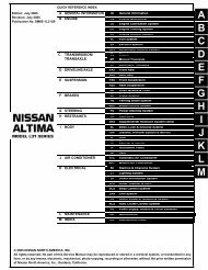
Step 2 Installation Screen<br />
A dialog will be displayed with five installation options.<br />
Illustration 3: Installation: STW dialog box<br />
It is recommended that users also have Internet Explorer 6.0 and Adobe Acrobat 6.0<br />
they are available during this installation. A Third Party CD is included.<br />
Select "STW for Earthmoving" to launch the Service Technician Workbench 2006A<br />
installation. Service Technician Workbench will be installed with the exception of<br />
Engine Performance Estimator.<br />
Refer to Step 3 to follow further installation instructions.<br />
Select "STW for Engines" to launch the Service Technician Workbench 2003B<br />
installation. Service Technician Workbench will be installed with the exception of M300<br />
Technician and Challenger Technician.<br />
Refer to Step 3 to follow further installation instructions.<br />
Select "SIS Standalone" to launch the Service Information System 2006A installation.<br />
With this selection the SIS icon will be placed on the users desktop.<br />
Select "CAT ET Standalone" to launch the Electronic Technician 2006A installation.<br />
With this selection the ET icon will be placed on the users desktop. Note: To install ET<br />
standalone and STW, first install ET standalone, then re-start the installation and install<br />
STW. This will put both the ET and STW icon on the desktop.<br />
10
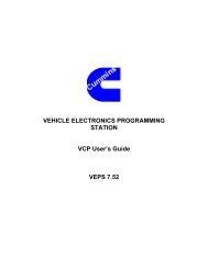
Illustration 4: The STW setup will check your setup<br />
Step 3 Close All Programs<br />
A dialog will be displayed to remind you to close all other programs before running the<br />
Service Technician Workbench installation. If you have programs open click “Cancel”,<br />
close all programs and restart the STW installation. If all programs are closed click “OK”<br />
to continue with the installation.<br />
Illustration 5:<br />
Click “OK” to continue with the setup program.<br />
Step 4 Welcome Screen<br />
The Welcome Screen will appear the first time Service Technician Workbench is<br />
installed on a computer.<br />
Select the “Next” button.<br />
11
Illustration 6: Welcome dialog box<br />
Step 5 Software License Agreement<br />
Illustration 7: Software License Agreement dialog box<br />
The Software License Agreement dialog is used to display the terms of the License<br />
Agreement that Caterpillar Inc. expects from its users. All applications will be<br />
represented under this single License Agreement. Please read the Agreement.<br />
12
Select the “Yes” button to continue. If you select the “No” button, your STW installation<br />
will terminate.<br />
Step 6 Installation Information – Please read the installation information.<br />
This screen provides an explanation of the installation process.<br />
Illustration 8: Select the “Next” button.<br />
Illustration 8: Information dialog box<br />
Step 7 Select Languages<br />
The Select Languages dialog is used to select the languages that all STW applications<br />
will be able to support.<br />
13
Illustration 9: Select Language dialog box<br />
Select the language(s) that you want Service Technician Workbench and Service<br />
Information System to use. Select the “Next” button.<br />
All Service Technician Workbench applications support English.<br />
14
Step 8 Select Components<br />
The Select Components dialog allows the user to select the applications to be installed<br />
as well as the location (drive and subdirectory). Flash File Search will be installed if SIS<br />
was previously installed. You may uncheck any applications you do not wish to install.<br />
All the selected applications will be reinstalled to the same folder as the previous<br />
installation. To deselect an application, click on the check box in front of the name.<br />
Illustration 10: Select Components dialog box<br />
If you accept the default locations, select the “Next” button and go to Step 11. If you<br />
choose to install some components on alternative drives, continue below.<br />
The Select Components dialog box indicates how much disk space your hard drive has<br />
available and how much is needed for the components you have chosen. If there isn’t<br />
enough disk space available then you need to do one or more of the following:<br />
A. Deselect some of the components.<br />
B. Install some of the components to another hard drive (if you have another one)<br />
by selecting the “Change Folder” button. You will need to highlight each component and<br />
do this.<br />
C. Remove some other files or applications from your hard drive to provide<br />
additional disk space.<br />
Select the applications to be installed by placing a check in each box. Select the “Next”<br />
button.<br />
NOTE: When Setup is Complete It is recommended that the user restart (reboot) the<br />
computer before operating Service Technician Workbench.<br />
15
This section will describe the recommended steps necessary to uninstall the Service<br />
Technician Workbench applications. To uninstall the software a user must use the STW<br />
Installation CD. The STW Installation CD is the only recommended method of<br />
uninstalling STW.<br />
Uninstalling Using the Installation CD<br />
Step 1 To uninstall STW, insert the STW CD into the CD or DVD drive. The<br />
installation procedure will automatically start if the computer has the autorun feature<br />
enabled. Skip ahead to<br />
Step 2.<br />
If the installation procedure does not automatically start, do the following:<br />
A. Insert the STW CD into the CD or DVD drive.<br />
B. Select the “Start” button from the Windows desktop screen, select “Run”, and<br />
then select “Browse.”<br />
C. Navigate to the CD or DVD drive, select the file named “stw.exe” (or setup), and<br />
then click on the “Open” button. The “Run” window should have stw.exe listed in the<br />
open dropdown box.<br />
D. Select the “OK” button in the Run window. The Service Technician Workbench<br />
installation process will now begin.<br />
E. The Choose Setup Language dialog should appear.<br />
Step 2 Choose Setup Language<br />
The Choose Setup Language dialog determines the language in which the installation<br />
instructions will be displayed. It does not determine which languages will be installed for<br />
Service Technician Workbench.<br />
Step 3 Select “Remove All…” from the Installation dialog.<br />
Step 4 A verification dialog will verify you want to uninstall STW. Select “Yes.”<br />
Step 5 The progress indicator will display what is being uninstalled.<br />
Step 6 If SIS was installed, the SIS installation will start.<br />
16
Frequently Asked Questions<br />
If you are having a problem installing or using your software, here are some tips to get<br />
you started! First, please make sure you have thoroughly read the Getting Started<br />
section of this booklet. If you have followed the directions and are still having trouble<br />
installing or operating the software, here are some frequently asked questions and<br />
solutions that might help solve your problem.<br />
Q) Why is there no longer a SIS icon on the desktop after installing STW?<br />
A) The SIS icon is removed when STW is installed because SIS is now accessed<br />
through STW.<br />
Q) Cat ET was licensed on my PC, but the license did not transfer after I installed<br />
STW?<br />
A) On most PC'S the Cat ET license transfers automatically to STW. Use on-line<br />
licensing at https://on-linelicensing.cat.com./<br />
Q) Are TCP/IP and Dial-up Networking needed for STW and SIS to communicate?<br />
A) TCP/IP and Dial-up Networking are not needed for STW to communicate with<br />
SIS. They are needed for SIS to communicate with Service Advisor or DBS<br />
through Parts Integrator. TCP/IP and Dial-up Networking are also needed to<br />
send and receive Feedback from STW.<br />
Q) How do I access SIS Web through STW?<br />
A) Click on the same icon in the STW launch pad that you would to access SIS<br />
Windows. There is a preference setting in STW that indicates which application<br />
should launch. In STW Select View > Preferences and then select the SIS tab.<br />
Select SIS WEB. You must restart STW before the setting will take affect.<br />
Q) Why do I have to sign into SIS Web even though I’ve already signed into STW?<br />
A) The STW and SIS Web users exist independently of each other. Your SIS Web<br />
user is based on your Corporate Web Security (CWS) ID. To get through Caterpillar’s<br />
internet security, you will still need to sign in using your CWS ID and password which is<br />
not currently tied to the STW users created on your machine.<br />
Q) Why do M300 Technician, Challenger Technician, and DataView launch over the<br />
top of STW in their own window, Cat ET, SIS DVD, SIS Web, CBT, run within the STW<br />
window?<br />
A) These applications are not integrated with STW and launch outside of the STW<br />
container.<br />
Q) How do I get a SIS Web account?<br />
A) Talk to the SIS Coordinator or SIS Administrator at your dealership. He/She<br />
should be able to help you get a CWS user ID and then give you access to SIS Web. If<br />
your SIS Coordinator has questions, have them contact the DCS support center at 800-<br />
765-0999 or dcs_support_center@cat.com.<br />
Q) Why won’t my old SIS library work with STW?<br />
A) If your SIS library is pre-May 2006, You will need to have a new SIS library<br />
version. May 2006 or later. You can get this by calling your SIS Coordinator.<br />
17
Q) How do I send Feedback?<br />
A) Click on the Feedback icon (first icon on tool bar) and answer questions.<br />
- If you are connected to your dealer network, click on the<br />
“Send/Receive” button.<br />
- If you are not connected to a network, then click on<br />
“Export” and then “Feedback to Caterpillar” and save it on a<br />
floppy.<br />
- If you get a message that you were not able to transmit to<br />
the ftp.cat.com connection, then contact your Information<br />
Systems (IS) department. Your dealership’s firewall may be<br />
preventing you from sending Feedback. Your IS contact<br />
can contact the Help Desk (Service Systems Support<br />
Center) for help on this issue. The DCS Support Center’s contact<br />
information is near the end of this document.<br />
Q) How is SIS Web feedback different from STW feedback?<br />
A) All feedback comes into the DCS support center. Feedback from SIS Web will<br />
record the page that you were on when you selected to send feedback. In a similar way,<br />
STW feedback will record what you were doing in the application you were in when you<br />
selected to send feedback. Sending feedback from the appropriate application will help<br />
first and second level support correctly diagnose the issue or assign it to the appropriate<br />
team.<br />
Q) Why is Internet Explorer 6.0 (IE 5.5) required for the Service Technician Workbench<br />
to operate?<br />
A) STW requires IE 6.0 or higher for the STW Report Utility.<br />
Q) Why does the SIS user name and password have to be the same as the STW<br />
user name and password?<br />
A) Using the same password allows the user to sign in just one time in order to use<br />
all the STW tools.<br />
Q) Why are there two different user administration tools? Why can't SIS and STW<br />
use the same user administration tool?<br />
A) These programs will continue to be improved. We are in the process of<br />
integrating the two software packages. A single user administration tool is<br />
planned for a future release of Workbench. We’ll keep you updated.<br />
Q) Why is Flash File Search (FFS) not working with Network SIS on my computer?<br />
A) If you installed May SIS Setup CD to use SIS CD’s/DVD’s, FFS is installed on<br />
your PC Hard Disk Drive. If you now decide to point SIS to Network data, install<br />
the May SIS Network Setup CD to enable FFS to work with Network SIS.<br />
Q) Why isn’t the FFS icon on the launchpad?<br />
A) FFS icon is not displayed when the SIS preference is set to SIS Web. You must<br />
change the SIS preference settings to SIS DVD.<br />
18
Q) How do I subscribe to SIS and/or Cat ET?<br />
A) It’s simple! Contact Caterpillar Media and Product Information Logistics at<br />
https://on-linelicensing.cat.com. You may also e-mail: media-logistics@cat.com.<br />
Q) What do I need to do if I get a new computer?<br />
A) With your old computer, first export Bookmarks to a floppy or network drive. Next,<br />
copy Service Reports that are in the .pdf and .xml formats to a floppy or network drive<br />
(default location is Program Files/STW/STW/Rptfile).<br />
When the new computer is in place, make certain STW has been installed. Go<br />
into the STW User Administration, which is on the desktop, and populate as much<br />
information as possible. Doing so will allow some of this same information to be<br />
populated when generating Feedback or a Service Report. If STW is installed, log into<br />
STW and import the Feedback and Bookmarks from floppy or network drive. Next you<br />
will need to Transfer the license to the new computer after STW is installed. Go to:<br />
https://on-linelicensing.cat.com or contact your SIS coordinator to transfer the license. Make<br />
certain that STW is working as expected on the NEW pc. Uninstall STW from old PC to<br />
prevent any unauthorized usage.<br />
Q) How do I receive responses to “Feedback”?<br />
A) Click the “Feedback” icon then click “Send/Receive”. This button is used to both<br />
send and receive “Feedback” communication. If you have received a “Feedback”<br />
response then you will have a dialog box with instructions on viewing or saving the<br />
response.<br />
Q) Why does the Feedback feature not work?<br />
A) STW uses the internet to send the Feedback to Caterpillar. Make sure the<br />
computer’s modem is properly configured. Go to your computer desktop, then to<br />
Start/Settings/Control Panel. Highlight “Network/TCP/IP -> Dial-Up Adapter” and choose<br />
Properties/DNS Configuration/Enable DNS. Then contact your IS department to obtain<br />
your “Host” and “Domain Suffix Search Order” and enter these in the appropriate boxes<br />
and click “OK”. Restart your computer when prompted. If you are still having problems,<br />
refer to the previous questions and answers related to sending and receiving Feedback.<br />
Q) How do I save a completed Service Report?<br />
A) The STW user now has the choice to save the Service Report in either the .xml<br />
format or .pdf format. The Adobe .pdf should be used only if the service report<br />
does not need to be updated. The .xml format should be used to allow update<br />
and share with the office administrators. To save a service report click the “Save”<br />
icon on the STW tool bar<br />
Q) How do I open a completed Service Report?<br />
A) The service report must be saved using the .xml format to open in STW. Select<br />
File>Session>From Report to open a service report back into the STW session.<br />
19
Q) How can I have the logo for my dealership appear in the top right hand corner of<br />
the STW Service Report?<br />
A) First, find the image you want and name it “dealer.jpg”. Next, copy the file into:<br />
“C:\Program Files\Caterpillar Inc\Service Report\Themes\Logos”. Restart STW and the<br />
next time an STW Service Report is generated your image will be in the top right hand<br />
corner.<br />
Q) Why aren’t my digital images, Cat ET reports, or Cat ET graphics being displayed<br />
in the STW Service Report?<br />
A) Launch the STW Service Report and choose View, Preferences from the menu.<br />
The Service Report Preference tab will be displayed. Verify that the checkboxes for<br />
Digital Images is selected.<br />
20
Purpose<br />
If communicating Service Information System (SIS) with DBS through Parts Integrator<br />
or SIS with Service Advisor, then a computer protocol named TCP/IP needs to be<br />
installed on your PC.<br />
Sending and receiving Feedback using STW also requires the computer protocol<br />
TCP/IP.<br />
If SIS does not communicate with DBS through Parts Integrator or Service Advisor, then<br />
follow the instructions below to resolve the problem. Also refer to the following<br />
instructions if you are unable to send or receive Feedback in STW.<br />
Step 1 Installing Dial-up Networking<br />
Windows 2000:<br />
A. Double click the “My Computer” icon on your desktop.<br />
B. In “My Computer”, double click the “Control Panel” icon.<br />
C. In the “Control Panel”, choose “Network” and “Dial-Up Connections”.<br />
D. Choose “Local Area Connection Status”.<br />
E. Click on “Properties” and choose “Install”.<br />
F. Select “Protocol: and then the “Add...” button.<br />
G. Choose “TCP/IP” from the list.<br />
H. Installation will proceed.<br />
I. After the installation has completed, restart your computer.<br />
Windows XP:<br />
TCP/IP is automatically installed with Windows XP.<br />
Step 3 If communicating between SIS and DBS through Parts Integrator, then try<br />
to use it. If communicating between SIS and Service Advisor, then try to use it.<br />
If sending and receiving Feedback in STW, then try to use it.<br />
Contact the DCS Support Center if you continue to have problems. The DCS Support<br />
Center’s contact information is near the end of this document.<br />
21
Cat ET Standalone Computer Hardware Recommendations<br />
In order to successfully run Caterpillar Electronic Technician in standalone mode, you will need the<br />
following computer hardware:<br />
Cat ET Standalone PC Configuration<br />
• IBM® PC compatible with Pentium IV 2.4 GHz processor<br />
• 512 MB RAM<br />
• 1 GB of available hard disk drive<br />
• 40X speed CD-ROM drive or 8X speed DVD drive<br />
• File Transfer Devise (USD Key or 3.5" 1.44 MB floppy disk drive, etc.)<br />
• 14.1 inch XGA color monitor or display (800x600)<br />
• Windows 2000, XP<br />
• RS232 port with 16550AF UART or PCMCIA card to RS232 adapter or USB to RS232<br />
adapter (Cat part # 237-7547)<br />
• Built in pointing device or mouse<br />
• Microsoft® Internet Explorer 5.5 or higher<br />
You will also need the following communication hardware, cables, and software to run<br />
Caterpillar Electronic Technician:<br />
171-4400 Caterpillar Communication Adapter II Group<br />
Included in this group is:<br />
Part Number Description<br />
171-4401 Caterpillar Communication Adapter II<br />
207-6845 Data Link Cable (24-inch)<br />
This cable must be used for J1939/11 communications<br />
196-0055 Serial PC Cable (25-foot)<br />
6V-3072 Carrying Case<br />
177-4595 Block/Foam for carrying case<br />
NEHS0758 Communication Adapter II CD and User’s Manual<br />
Optional Cables:<br />
Part Number Description<br />
7X-1686 In-Cab Adapter Cable for ATA<br />
157-4829 In-Cab Adapter Cable for the J1939/11<br />
160-0142 Serial PC Cable (10-foot)<br />
This cable can only be used with the<br />
Caterpillar Communication Adapter II 171-4401<br />
139-4166 ATA/CDL Unicable from Communication Adapter II to the service<br />
connector<br />
Note: You may also use the 7X-1412 ATA or 7X-1570 CDL cable. However, these are<br />
no longer available for purchase from Caterpillar Inc.<br />
140-9442 ATA/CDL T-Adapter (not required for all applications)<br />
167-9225 Cable Assembly used when Cab<br />
Diagnostic Connector is not available (not required for all applications)<br />
225-5985 Parallel Cable<br />
237-7547 USB to Serial Adapter<br />
22
- OR -<br />
7X-1700 - Caterpillar Communication Adapter Group<br />
Also requires:<br />
Part Number Description<br />
NEXG4523 Communication Adapter Software SPM (Service Program Module)<br />
Version 1.2 or greater<br />
7X-1425 RS232 Serial PC Cable<br />
This cable can only be used with the<br />
Caterpillar Communication Adapter<br />
7X-1701<br />
139-4166 ATA/CDL Unicable from Communication Adapter II to the service<br />
connector<br />
Note: You may also use the 7X-1412 ATA or 7X-1570 CDL cable. However, these are<br />
no longer available for purchase from Caterpillar Inc.<br />
140-9442 ATA/CDL T-Adapter (not required for all applications)<br />
- OR -<br />
MPSI Pro-Link® 9000 (only for On Highway Truck engines and certain commercial<br />
applications).<br />
Also requires:<br />
Description<br />
MPSI PC/Terminal Cable<br />
MPSI Caterpillar Cartridge (version 1.07 or greater)<br />
Exceptions:<br />
The requirements for Challenger Technician (CT), M300 Technician (M300), and<br />
Hydraulic Excavators are:<br />
CT 1U-9100 Cable Assembly - Challenger to PC Adapter cable<br />
M300 126-7877 Cable Assembly - M300 to PC Adapter cable<br />
HEX: 127-9797 Cable Assembly - HEX to PC Adapter cable<br />
Requirements<br />
171-4400 - Caterpillar Communication Adapter II Group<br />
Included in this group is the following equipment:<br />
Part Number Description<br />
171-4401 Caterpillar Communication Adapter II<br />
207-6845 Data Link Cable (24-inch)<br />
This cable must be used for J1939/11 communications<br />
196-0055 Serial PC Cable (25-foot)<br />
6V-3072 Carrying Case<br />
177-4595 Block/Foam for carrying case<br />
NEHS0758 Communication Adapter II CD-ROM and User’s Manual<br />
Optional Cables:<br />
Part Number Description<br />
7X-1686 In-Cab Adapter Cable for ATA<br />
23
157-4829 In-Cab Adapter Cable for the J1939/11<br />
160-0142 Serial PC Cable (10-foot)<br />
This cable can only be used with the<br />
Caterpillar Communiction Adapter II<br />
171-4401<br />
139-4166 ADA/CDL Unicable from a Caterpillar communication adapter to the<br />
service connector<br />
Note: You may also use the 7X1412 ATA or 7X1570 CDL cable. However, these are no<br />
longer available for purchase from Caterpillar Inc.<br />
140-9442 ATA/CDL T-Adapter (not required for all applications)<br />
167-9225 Cable Assembly used to connect your service tool directly to the ECM<br />
Instructions<br />
To connect the Communication Adapter II to the PC, perform the following steps:<br />
Step 1 Align and attach one end of the serial cable to the PC cable connection on<br />
the Communication Adapter II.<br />
Step 2 Connect the other end of the cable to the serial port of your PC.<br />
To connect the Communication Adapter II to the data link, perform the following steps:<br />
Step 1 After you have connected the Communication Adapter II to your PC,<br />
connect one end of the data link cable to the data link connection on the<br />
Communication Adapter II.<br />
Step 2 Connect the other end of the data link cable to the service connector on<br />
the product you wish to test. If the data link is powered (machine power is on), the<br />
Power light on the Communication Adapter will glow and the diagnostic test will begin.<br />
The lights on the front of the Communication Adapter II will sequentially glow from the<br />
bottom to the top of the device. You are now ready to start the service tool.<br />
Requirements<br />
7X1700 - Caterpillar Communication Adapter Group<br />
Also requires:<br />
Part Number Description<br />
NEXG4523 Communication Adapter Software SPM (Service Program Module)<br />
Version 1.2 or greater<br />
7X-1425 RS232 Serial PC Cable<br />
This cable can only be used with the<br />
Caterpillar Communication Adapter 7X1701<br />
139-4166 ATA/CDL Unicable from a Caterpillar communication adapter to the<br />
service connector<br />
Note: You may also use the 7X1412 ATA or 7X1570 CDL cable. However, these are no<br />
longer available for purchase from Caterpillar Inc.<br />
140-9442 ADA/CDL T-Adapter (not required for all applications)<br />
167-9225 Cable Assembly used to connect your service tool directly to the ECM<br />
24
Instructions<br />
To set up the Communication Adapter, perform the following steps:<br />
Step 1 Connect the 7X-1425 RS232 cable to an available COM Port on your PC<br />
and to the Service Tool connector on the Communication Adapter.<br />
Step 2 Connect the 139-4166 Unicable to the Control connector on the<br />
Communication Adapter and to the service connector on the product that you are<br />
servicing. You are now ready to start your service tool.<br />
Requirements<br />
MPSI Pro-Link® 9000 (only for On Highway Truck engines and certain commercial<br />
applications).<br />
This package also requires the following equipment:<br />
Description<br />
MPSI PC/Terminal Cable<br />
MPSI Caterpillar Cartridge (version 1.07 or greater)<br />
Instructions<br />
Perform the following steps to set up the Pro-Link® 9000:<br />
Step 1 Insert the MPSI Caterpillar Cartridge in the Pro-Link® 9000.<br />
Step 2 Connect the Pro-Link® 9000 to your PC's serial port using the MPSI<br />
PC/Terminal cable.<br />
Step 3 Connect the Pro-Link® 9000 to the product and turn the ignition key<br />
of the vehicle on to power the Pro-Link.<br />
Step 4 Select Pro-Link from the main menu or push the "Func" key to<br />
recall data if no engine data is received.<br />
Step 5 Select the Com Adapter Link function from the Pro-Link<br />
menu, and push "Enter" to initiate the Com Adapter Link mode. The Pro-Link will display<br />
a screen showing that the Com Adapter Link is active. You are now ready to start the<br />
service tool.<br />
See Installing STW on page 10 of this manual.<br />
Purpose<br />
Trainer runs the service tool in a training mode. This allows you to become familiar with<br />
the service tool without needing to be connected to an Electronic Control Module (ECM)<br />
or Communications Adapter. There is no charge for Trainer, and authorization is not<br />
required.<br />
Illustration 30: Trainer menu functions<br />
Instructions<br />
Using Trainer:<br />
Step 1 Select Caterpillar ET from the Programs menu, and then select Electronic<br />
Technician from the submenu. The Connection message box is displayed.<br />
Connection message box<br />
Step 2 Press the "Stop Connect" pushbutton. The service tool main screen is<br />
displayed.<br />
25
Step 3 Select Trainer from the Help menu, and then select Enable from the<br />
submenu, or push the Enable Trainer icon on the toolbar (if default is set). The Trainer<br />
dialog box is displayed.<br />
Trainer dialog box<br />
Step 4 Select a product from the Application drop-down list.<br />
Step 5 Press "OK." The Connection message box is displayed. The ECM<br />
Summary screen displays in the trainer mode (Refer to Illustration 33). Trainer<br />
simulates some of the service tool functions.<br />
Press "Cancel" to exit Trainer. You will return to the service tool main screen.<br />
Trainer screen<br />
To change the product simulated within Trainer:<br />
Step 1 Select Trainer from the Help menu, and then select Properties from<br />
the submenu. The Trainer dialog box is displayed.<br />
Step 2 Select a different product from the Application drop-down list.<br />
Step 3 Press "OK." The Connection message box is displayed. Then the new<br />
product is displayed.<br />
To exit Trainer:<br />
Select Trainer from the Help menu, and then select Disable on the submenu, or<br />
push the Disable Trainer icon from the toolbar (if default is set).<br />
Purpose<br />
What's New allows you to view a list of new functions and major enhancements<br />
available in the installed version of the service tool.<br />
What's New launches your browser when it is selected from the Help drop down. What's<br />
New is displayed in the language selected as default in the Select Default Language<br />
dialog box during the installation of your service tool. If an Internet browser is not<br />
installed on the PC, What's New is displayed in *.txt format.<br />
What’s New screen using a browser<br />
Instructions<br />
To view the What's New screen, select What's New from the Help menu<br />
Power Management<br />
Turn off Power Management (for example a screen saver or "sleep" mode) when using<br />
your service tool. Communication to the ECM might be interrupted if the PC "suspends."<br />
Infrared Communication Problems<br />
If your computer supports infrared communication, you may experience some<br />
communication problems with the service tool. It is recommended that you disable the<br />
infrared option. If you need help with this procedure, please contact the computer<br />
manufacturer.<br />
Disk Defragmentation/Disk Compression<br />
26
The service tool will remain unaffected by Disk Compression and/or Defragmentation<br />
programs as long as the compression/defragmentation programs do not move hidden or<br />
system files during the process.<br />
Windows 2000, and XP Installation<br />
Administrative rights are required to install Cat ET for the first time. Most upgrades do<br />
not require administrative rights.<br />
Error Code LIC0102<br />
The Windows (tm) driver appears not to be serving this directory.<br />
The CrypKey License service is not started, or the service is not protecting the Cat ET<br />
directory. To determine if the CrypKey License service is started, select Services from<br />
the Control Panel (in Windows(tm) 2000, select Administrative Tools from the Control<br />
Panel), then select services. CrypKey License should appear in the service list. If the<br />
CrypKey License service is not started, then the service needs to be started. If it is not<br />
there, then re-install the service tool.<br />
Note: The user must have administrative rights to add a directory.<br />
To start the service:<br />
Run the SETUP_CK.EXE program located in the windows directory (i.e. C:\WINDOWS\<br />
). Once the CrypKey License service is started, it automatically starts every time the<br />
system starts (Any user can then log in and use the CrypKey License service.).<br />
If the CrypKey License service is running and you still get the LIC0102 error code, then<br />
the problem may be that the service tool path is not protected. Run the<br />
CKCONFIG.EXE program located in the Windows (tm) directory (i.e. C:\WINDOWS\ ).<br />
The service tool directory must be listed in the CrypKey NT Server Configure window. If<br />
it is not, it must be added.<br />
To add the service tool directory, do the following:<br />
Press the "Add" pushbutton. The Open dialog box is displayed. Choose ETECH.EXE in<br />
the service tool directory (i.e. C:\Program Files\Caterpillar Electronic Technician\), and<br />
press "OK." Press the "Close" pushbutton. If you get an "Internal Error Open SC<br />
Manager" failure when the CrypKey NT Server Configure program was closed, you may<br />
not have Administrator privileges. Therefore, the CrypKey License server was not<br />
updated.<br />
Selecting the Correct Port<br />
Select Preferences… on the Utilities menu. The Preferences dialog box is displayed.<br />
Select the Communications tab.<br />
Laptops:<br />
If you use the built-in pointing device on your laptop PC, your first available port is<br />
usually COM 1.<br />
Personal Computer (PC):<br />
If your PC has a mouse with a round plug, your first available port is usually COM 1. If<br />
your PC has a mouse that DOES NOT have a round plug, your first available port is<br />
usually COM 2. If your PC DOES NOT have a mouse, your first available port is usually<br />
COM 1.<br />
Communication Errors<br />
Two types of error messages display when communication problems occur.<br />
Understanding these messages can help you correct the situation.<br />
27
"Unable to Communicate with an ECM!"<br />
This is a problem between the communication interface device and the ECM. The PC<br />
did detect the communication interface device. Make sure all connections between the<br />
communication interface device and the ECM are secure and intact. If the error displays<br />
again, verify that you are using the correct cables for your application.<br />
A. Check all connections between the PC and the ECM.<br />
B. Verify that you are using the correct cables for your application.<br />
C. Verify that the ECM has power.<br />
"Unable to Communicate with the Caterpillar Communication Adapter!"<br />
This error refers to a problem between the PC and the Communication Adapter.<br />
D. Check all connections between the PC and the ECM.<br />
E. Check that the Communication Adapter is receiving external power. The product<br />
being serviced must have the key switch on for power, unless it is connected directly to<br />
a battery.<br />
F. Verify in Preferences, under the Settings menu, that the correct port is selected.<br />
G. Verify in Preferences, under the Settings menu, that the correct Communication<br />
Interface Device is selected.<br />
H. If the error displays again, verify that you are using the correct cables for your<br />
application.<br />
I. Verify that your PC Comm Port is set up correctly and is not in use by another<br />
device (for example Palm Pilot Software). Try using another Comm Port, if it is<br />
available.<br />
Caterpillar Communication Adapter II Error Codes:<br />
When calling for software support, report the error code number to the support staff<br />
member. This will aid in solving the communication problem. The chart below is a list of<br />
error codes and the possible solutions to those errors.<br />
Error<br />
Code Error Description Suggestion<br />
--- No initialization file present. Un-install and re-install the Cat Comm Adapter<br />
II software. Make sure you reboot the PC after the installation is complete.<br />
--- Unable to read Cat<br />
Communication Adapter (RP1210) Initialization File. If the PC has Cat Comm Adapter<br />
II software installed, try rebooting the PC first. If this does not cure the problem, reinstall<br />
the Cat Comm Adapter II software. Make sure you reboot the PC after the<br />
installation is complete.<br />
--- Unable to load CA2RP32.DLL If the PC has Cat Comm Adapter II software<br />
installed, try rebooting the PC first. If this does not cure the problem, re-install the Cat<br />
Comm Adapter II software. Make sure you reboot the PC after the installation is<br />
complete.<br />
142* The interface hardware is not connected. Check the cables. Make sure the<br />
data link cable and serial communication cables are<br />
properly connected.<br />
Verify the Cat Comm Adapter II "Power" light is on.<br />
Check that Caterpillar<br />
Electronic Technician is configured for the correct communications port.<br />
28
202 A required INI file was not located. Un-install and then re-install the Cat<br />
Comm Adapter II software. Make sure you reboot the PC after the installation is<br />
complete.<br />
204 A required INI file<br />
section was not found. Un-install and then re-install the Cat Comm Adapter II<br />
software. Make sure you reboot the PC after the installation is complete.<br />
205 A necessary INI file key was not found. Un-install and re-install the Cat Comm<br />
Adapter II software. Make sure you reboot the PC after the installation is complete.<br />
206 An INI file value was invalid Un-install and then re-install the Cat Comm<br />
Adapter II software. Make sure you reboot the PC after the installation is complete.<br />
230 Port not open Another program or device is currently using the com port or<br />
the com port's resources.<br />
Identify the source and remove or disable it. Palm Pilot software commonly causes this<br />
error.<br />
231 Invalid Comm Port The selected comm port is not set up properly in the PC's<br />
BIOS or operating system.<br />
300 A device driver could not be opened. Un-install and then re-install the Cat<br />
Comm Adapter II software. Make sure you reboot the PC after the installation is<br />
complete.<br />
301 Cannot open the<br />
configuration file. Un-install and then re-install the Cat Comm Adapter II software.<br />
Make sure you reboot the PC after the installation is complete.<br />
302 The session identifier was not found in the<br />
configuration file. Un-install and then re-install the Cat Comm Adapter II software.<br />
Make sure you reboot the PC after the installation is complete.<br />
303 An error was found in the configuration file format. Un-install and then reinstall<br />
the Cat Comm Adapter II software. Make sure you reboot the PC after the<br />
installation is complete.<br />
308 A 16-bit client<br />
application is trying to use the Comm Adapter II, but the APISRV32.EXE file is missing<br />
or not in the default Windows<br />
directory. This only applies to Windows<br />
95/98. Re-install the Comm Adapter II software. Make sure you reboot the PC after the<br />
installation is complete.<br />
405 The PC had a problem while trying to establish the communication baud rate with<br />
the Comm Adapter II. Power cycle the Comm Adapter II and reboot the PC. If the<br />
error persists, lower the<br />
communication baud rate.<br />
406 The PC tried to establish a connection to the Comm Adapter II, but ran into a<br />
problem during the communication<br />
initialization phase. This error code occurs during the communication initialization<br />
phase when the specific stage is not identified. Error codes 142, 405, 441, or 453 relate<br />
to<br />
specific stages in the<br />
initialization process.<br />
441 The requested protocol is not compatible with an existing data link. Cycle the<br />
power on the Cat Comm Adapter II and ECM. If this does not correct the<br />
problem, reboot the PC, and try again. Do not launch the Comm Adapter II Toolkit while<br />
Cat ET is running.<br />
29
446* The drivers software and the communiaction adapter Firmware are not<br />
compatible Install the appropriate Firmware onto the Communications Adapter II.<br />
453* The Communicaion Adapter has been detected but is not responding The<br />
Serial.vdx file in your<br />
Windows/System folder may be<br />
corrupt. Reinstall the Serial vdx file provided with Windows<br />
*For more information on Error Codes 142, 443, and 453, consult the Comm Adapter II<br />
Read Me file located in the Caterpillar Comm Adapter II Group Box (select Caterpillar<br />
Comm Adapter II from the Programs menu, then select Read Me from the submenu).<br />
Installation Error Codes:<br />
When calling for software support, report the error code number to the support staff<br />
member. This will aid in solving the communication problem. The chart below is a list of<br />
error codes and the possible solutions to those errors.<br />
Error<br />
Code Error Description Suggestion<br />
300 Unable to load DLL. Restart computer and run<br />
installation again.<br />
301 License Validation Failed (bad checksum on the file). A file may be damaged, try<br />
reinstalling the Cat ET Software.<br />
302 License validation Failed (Cat ET Version Check Failed). A file may be<br />
damaged, try<br />
reinstalling the Cat ET Software.<br />
303 License Validation Failed (An old serial number has been detected on this<br />
computer and cannot be updated). Need a new license before upgrading.<br />
304 You must have<br />
administrative rights to install Crypkey Service. Logon as an administrator and run setup<br />
again.<br />
305 Crypkey Installation Failed. Restart computer. logon as an administrator<br />
and run setup again.<br />
400 Cat ET must be installed into a subdirectory. Select a folder on the "Select<br />
Components" screen during setup (i.e. C:\Cat ET).<br />
403 "Version 1.6 or earlier was detected. Version 2001A cannot upgrade this from<br />
version. Upgrade to Version 2.1 first." Install ET 2.1 first. Run /ET21/Disk1/setup.exe<br />
on the ET CD, and then run Cat ET 2002A setup again.<br />
404 Cat ET cannot be installed onto a network drive. Please try again. Select a local<br />
drive (i.e. c: or d:) on the "Select Components" screen during setup.<br />
--- "The ODBC Setup Library is being used and is locked. Make sure no other<br />
program is running. Setup cannot continue." Close all programs and run setup again.<br />
You may need to restart the computer and run setup again. When using<br />
Windows. make sure there are no services using ODBC, such as "SQL Server." Make<br />
sure Control Panel is not open.<br />
30
Challenger Technician<br />
Purpose<br />
The Challenger Technician program is used to service Challenger 35, 45, and 55. For<br />
more information on Challenger Technician, refer to Challenger Technician Online Help.<br />
Equipment: 1U9100 Cable Assembly - Challenger to PC Adapter cable<br />
Instructions<br />
To connect your PC to the Challenger, do the following:<br />
Step 1 Connect the 1U9100 cable to the Diagnostic and Maintenance<br />
(DAM) connector, located in the cab of the Challenger.<br />
Step 2 Connect the remaining end of the 1U9100 cable to an available<br />
serial communication port on the PC.<br />
To start Challenger Technician:<br />
Select Caterpillar ET from the Programs menu, and then select Challenger Technician<br />
from the submenu. The Challenger Technician screen is displayed.<br />
M300 Technician<br />
Purpose<br />
The M300 Technician program supports the M312, M315, M318, and M320 excavators.<br />
For more information on M300 Technician, refer to the M300 Technician Online Help.<br />
Equipment: 126-7877 Cable Assembly - M300 to PC Adapter cable<br />
Instructions<br />
To connect your PC to the M300 series excavator:<br />
Step 1 Connect the 126-7877 cable to the service connector, located in the cab of<br />
the excavator.<br />
Step 2 Connect the remaining end of the 126-7877 cable to an available serial<br />
communication port on the PC.<br />
To start M300 Technician:<br />
Select Caterpillar ET from the Programs menu, and then select M300 Technician from<br />
the submenu. The M300 Technician screen is displayed.<br />
Caterpillar Electronic Technician Online Help<br />
Purpose:<br />
The Help Contents function allows you to access the online help file for your service<br />
tool. This file gives valuable information about each feature and provides step-by-step<br />
instructions for all service tool functions.<br />
Instructions<br />
To access the Help contents either:<br />
a. Select "Contents" from the Help menu.<br />
b. Push the F1 key (content sensitive).<br />
c. Press the Help icon on the toolbar, if the default is set.<br />
d. Select Caterpillar ET from the Programs menu, and then<br />
e. Select Electronic Technician Online Help from the submenu.<br />
31
Caterpillar Electronic Technician Read Me File<br />
Purpose<br />
The readme.txt file can be found on the service tool Install CD-ROM. It is also displayed<br />
as an icon in the service tool Group Box. This file contains last minute information about<br />
your service tool.<br />
Instructions<br />
Select Caterpillar ET from the Programs menu, then select Read Me from the submenu.<br />
The readme.txt file is displayed.<br />
Caterpillar Electronic Technician Infocast Website<br />
Illustration 35: Caterpillar Electronic Technician Infocast Website dialog box<br />
Overview<br />
Caterpillar Electronic Technician is available on the Infocast Website at the following<br />
locations:<br />
O. NACD Infocast:<br />
https://nacd.cat.com/infocast/frames/psfulfill/sfulfill/et/<br />
P. CAPL APDNet:<br />
https://catasia.cat.com/infocast/frames/pss/service/stw/et/<br />
Q. CCL APDNet:<br />
https://catchina.cat.com/infocast/frames/pss/service/stw/et/<br />
R. Power Net:<br />
https://engines.cat.com/infocast/frames/truck/service/catet/<br />
At this site you can:<br />
S. Learn about Caterpillar Electronic Technician.<br />
T. Download Caterpillar Electronic Technician, it's Service Packs, and<br />
Communication Adapter II software.<br />
U. Obtain part numbers and media numbers to order Caterpillar Electronic<br />
Technician.<br />
V. Review the PC Requirements to run Caterpillar Electronic Technician.<br />
W. Obtain the latest support information for Caterpillar Electronic Technician and<br />
Communication Adapter II.<br />
32
Dataview<br />
DataView measures and logs temperature, pressure, blow-by, position, RPM, frequency<br />
and pulse width on all Caterpillar products. Also monitors and tests the sensors on<br />
Caterpillar electronic controls either removed from the product or installed.<br />
You will need one of the following hardware/software packages to run DataView:<br />
131-5051 DataView Portable TechStation Group<br />
This group contains all of the cables and accessories needed to operate DataView,<br />
except the sensors. They must be ordered separately or can be taken from other<br />
Caterpillar Diagnostic tool groups you may have.<br />
131-5050 DataView Group<br />
This very basic group includes only the DataView hardware unit and the accessories<br />
necessary to power it and connect it to the PC. No sensors or sensor adapter cables<br />
are included. The memory card for data logging is not supplied and must be purchased<br />
separately, if desired.<br />
Flash File Search (FFS)<br />
Flash File Search (FFS) allows the user quick access to the latest Flash File information<br />
based on the Engine/Product Serial Number or Flash File Software Part Number.<br />
Users will need a SIS CD/DVD subscription, or they can select Network data in SIS<br />
Preferences as the SIS data source.<br />
Illustration 49: Flash File Search dialog box<br />
FFS will only work when the Flash File data CD's are the same month as the SIS Setup<br />
CD.<br />
Field SIS users can use the Flash File data CD's they receive every other month<br />
(without the SIS Setup CD). Use the "Update the Flash File database" icon on the FFS<br />
toolbar. This button will update the local SIS data. Users who receive SIS libraries every<br />
month do not need to click on the "Update the Flash File Database" icon.<br />
• Flash File Search Option: Type in either the Engine/Product Serial Number, or<br />
the Flash File Part Number, and click on the "Find Latest" button. Product<br />
searches will not include the engine. Engines must be searched separately.<br />
• Current Flash File Part Number: The latest three Flash File Part Numbers are<br />
displayed in a hierarchy. The newest Flash File is displayed first followed by two<br />
older Flash Files. Next to each Flash File part number will be the CD location.<br />
• Save: Select the latest file from the list and click on the "Save" button. From the<br />
Windows dialog displayed, choose the location to save.<br />
• Launch WinFlash: The user can select the "Launch WinFlash" button to go to<br />
WinFlash. The Flash File name (Part Number) and directory path will be passed<br />
from FFS to WinFlash. An example is: C:\Flash\Software\1234456.FLS.<br />
• Print: The user can also print the latest Flash File result by selecting the "Print"<br />
button and choosing a printer.<br />
Purpose<br />
The STW Report Utility is a standalone application included on the STW installation CD.<br />
The Report Utility allows for the creation of a new Service Report in STW Format (.xml)<br />
in 71 different languages. It also enables Service Reports saved in the STW Format<br />
(.xml) from within STW to be opened, edited, printed, and saved outside of STW. The<br />
33
STW Report Utility is for dealer personnel, such as clerks, who need to view, edit and<br />
print a service technician's Service Reports. The STW Report Utility is installed when<br />
STW is installed, but can be installed separately and used on a PC without STW.<br />
Installation<br />
A. Insert the STW CD into the PC's CD or DVD drive.<br />
B. Use "My Computer" or "Windows Explorer" to locate the folder titled "Report<br />
Utility”. Open this folder and double click on "Setup.exe".<br />
C. "Setup.exe" will install the STW Report Utility on the hard drive and also create a<br />
shortcut on the PC's desktop.<br />
Operation<br />
Double click on the STW Report Utility's shortcut icon on the desktop to launch the<br />
Report Utility. A blank Service Report will be displayed along with menu options and a<br />
toolbar.<br />
• To Create a New Service Report: Choose New from the File menu or click on the<br />
New icon in the toolbar.<br />
• To Open an Existing Service Report Saved in STW Format (.xml): Choose File,<br />
Open from the menu or click on the Open icon in the toolbar.<br />
• To Preview or Print a Service Report: Choose Print Preview or Print from the File<br />
menu or click on the Print Preview or Print icons in the toolbar.<br />
• To Save a Service Report: Choose Save from the File menu or click on the Save<br />
icon in the toolbar.<br />
File Menu<br />
• To Cut, Copy, or Paste Text: Choose Cut, Copy, or Paste from the Edit menu or<br />
click on the Cut, Copy, or Paste icons in the toolbar.<br />
Edit Menu<br />
• To Change the Language Settings: Choose Language Preferences from the<br />
View menu.<br />
View Menu<br />
• To Access Help: Select Help from the menu or click on the Help icon in the<br />
toolbar.<br />
Help Menu<br />
• To Add Lines to a Particular Section of the Service Report: Click on the Add Line<br />
button for that section.<br />
34
• To Delete Existing Lines from a Particular Section of the Service Report: Click on<br />
the Delete Line button for that section. Those lines with checkmarks next to them will<br />
be removed.<br />
DBS Labor Entry and Approval Setup<br />
DBS Reference document: Adding Labor – DBS Chapter 6 or Direct Labor<br />
Approval – DBS Chapter 6<br />
DBS must be setup to approve labor before labor is uploaded using the SIMS DBS<br />
utility. Approval is required for all labor that is uploaded to DBS using the SIMS DBS<br />
upload utility. The list of commands that follow is required to setup and approve labor in<br />
the DBS system. When the initial setup is complete, the approver will use the<br />
MNTWOAPPV screen to approve labor. The technician uploading labor to DBS will not<br />
need additional DBS access to complete the labor upload.<br />
Access to DBS Screens Needed to Setup the STW Labor Upload<br />
The screens listed below are required to setup direct labor approval within DBS. The<br />
person setting up this functionality should check to see if they are permitted access to<br />
each of the screens that follow before beginning the labor approval setup process. If<br />
necessary, make a list of the screens below that the setup person cannot access and<br />
then call the DBS person responsible for granting access to these screens. This will<br />
eliminate the need to call the DBS administrator numerous times.<br />
MNTWOCTL (Direct Labor to Approval Indicator) The direct labor to approval indicator<br />
must be set to YES to enable labor to be uploaded through the SIMS/DBS upload utility.<br />
Uploaded labor through the STW upload utility requires approval.<br />
MNTWOAPR (Approver Maintenance) Setup the persons responsible for approving<br />
labor with this screen.<br />
MNTWOSHF (Work Day Maintenance) The workday (hours) for the employee is setup<br />
and assigned a code. Each technician will be assigned a workday code within the<br />
MNTWOEMP@ screen.<br />
MNTWOEMP2 (Empl. Maint.-Lbr Collection) (Employee cross reference) The employee<br />
ID, approver group and workday code will be entered in this area to permit the<br />
employee to enter and upload labor to DBS.<br />
MNTWOEMP (Employee Function) Maintain the employee’s personal information with<br />
this screen.<br />
MNTWOAPPV (Accept labor entries) The people responsible for approving labor will<br />
use this screen to review and approve labor.<br />
DSPWOEMP (Employee Inquiry) Obtain work order information from this screen. (Not<br />
discussed in this document. Refer to the DBS reference document listed earlier.)<br />
LSTWOARCH (Archive Labor Audit) Manage or archive information from this DBS<br />
screen (Not discussed in this document. Refer to the DBS reference document listed<br />
earlier.)<br />
35
Illustration 11:<br />
This document provides the directions to complete the Work Day Code, Employee<br />
Cross Reference and the Approver Id and Group screens within DBS. These screens<br />
are necessary to implement the DBS labor approval process. The Labor Sell Rate and<br />
the Employee screens within DBS are not discussed in this document. Third Party<br />
Software may supply an employee badge number. If the number is different than the<br />
DBS employee ID, it may be necessary to include that information. Refer to the third<br />
party software for more information if third party software is an issue.<br />
MNTWOCTL (Direct Labor to Approval Indicator)<br />
Labor Approval<br />
Labor Approval in DBS is used to approve pending labor records, update<br />
(split) a pending labor record, and change pending labor records. Labor<br />
approval is required when a time clock is used or if DBS is set up with Direct<br />
Labor to Approval Indicator set to Yes. The indicator is located within the<br />
(MNTWOCTL) function, under Store Print Queues (F10).<br />
When labor detail is added to a work order, it is held in a Pending Approval<br />
file. You can view both unapproved and approved labor using the Employee<br />
Labor Inquiry (DSPWOLBR) function. This function may also be used to<br />
analyze other aspects of employee labor records.<br />
Labor approval is completed in the Approve Labor (MNTWOAPPV) function.<br />
In order to access this function, you must be set up with an approver ID and be<br />
assigned to at least one approval group. The Approver Maintenance<br />
(MNTWOAPR) function is used to inquire and perform maintenance to<br />
approver identification information.<br />
Approved labor records remain on the system until they are archived and/or<br />
purged. The Archive Labor Audit (LSTWOARCH) function provides access to<br />
a batch process that can save these records to a diskette or tape and remove<br />
them from DBS.<br />
36
MNTWOCTL (Direct Labor to Approval Indicator)<br />
Labor Approval<br />
From within DBS, enter the MNTWOCTL command. The above screen may appear if<br />
MNTWOCTL has not been accessed in the past. Enter an appropriate store and name<br />
and select enter.<br />
37
Illustration 12: Select CF10 to go to the Labor Approval parameter. Enter CF10 again if<br />
the labor approval indicator is not visible.<br />
Illustration 13: Direct Labor to Approval must be set to Y (Yes) to upload labor to DBS<br />
from the SIMS DBS Upload Utility. All labor uploaded with the DBS upload utility will<br />
require approval by the appropriate personnel.<br />
MNTWOAPR (Approver Maintenance)<br />
a. The Approver Maintenance: (MNTWOAPR) function is used to inquire on<br />
and perform maintenance to approver identification information. This<br />
process will setup the people responsible for approving labor. Enter<br />
MNTWOAPR in the Transfer to data entry line and select enter.<br />
b.<br />
38
Illustration 14: Enter the intended approver’s ID and the approval group name,<br />
example FLD for field technicians and select F6 to add. The approver ID will be<br />
the person approving the labor for the group. The group name is the<br />
administrators’ choice. It might be FLD (field), SHP (shop), TVL (travel) ENG<br />
(engine) etc. Separate approval groups are required for each group of users that<br />
will upload labor or time. An approver can be responsible for more than one<br />
approval group. Select F6 to add the approver. Select F7 to change a current<br />
approvers group name. F7 is used to delete an approver’s responsibilities.<br />
39
Illustration 15: Enter the approver name and approval group description.<br />
Example screen. R Morse will be the approver for the shop technicians. The<br />
group name is SHP. Create as many approval groups as required. If more than<br />
one group of shop technicians is required, and specific technicians are to report<br />
to a specific approver, more than one group will need to be created. An example<br />
might be SHP1, and SHP2. Enter the approval group name for field technicians if<br />
field technicians will be uploading labor to DBS. A common group name for field<br />
technicians is FLD. If more than one group for field technicians is needed, give<br />
each group a unique name, FLD1, FLD2 etc. Assign the technicians to the<br />
specific approver and approver group. Creating two groups will enable two<br />
approvers and two groups of shop technicians. Repeat this procedure until all of<br />
the approvers and approver groups are set up. Multiple approvers may be setup<br />
to approve a group of technicians.<br />
40
Illustration 16: A question mark can be used to determine what groups an<br />
individual is responsible for. Enter the approver ID and a question mark in the<br />
approval group to query which groups the approver is responsible for.<br />
Illustration 17: R Morse is responsible for approving field technicians (FLD) and<br />
shop technicians (SHP).<br />
41
MNTWOSHF (Work Day Maintenance)<br />
Use the Work Day Maintenance (MNTWOSHF) function to review, add, change,<br />
and delete workday codes and start/stop rounding times. Workday codes are a<br />
required field in the Employee Cross Reference screens (MNTWOEMP2 that will<br />
be completed later.<br />
Illustration 18: Transfer to the MNTWOSHF screen. Enter/create the work day<br />
shift code or enter a question mark to query what shifts are available. Code 73<br />
could represent the day shift, from 7:00AM until 3:30 PM. If creating a new<br />
workday code, enter the workday code and select F6 to add.<br />
42
Illustration 19: Other shift time examples and code examples. A question mark<br />
was entered instead of a workday code in order to display all of the available<br />
workday codes.<br />
Illustration 20: Enter the workday start time, stop time and rounding if desired.<br />
Four characters are required in the start and stop times. To enter 7:00 AM enter<br />
0700. Enter 1530 for 3:30 PM. Repeat this procedure for all of the workday codes<br />
required.<br />
43
Transfer to the MNTWOEMP2 (Empl. Maint.-Lbr Collection) (Employee<br />
cross reference) screen.<br />
An employee cross-reference record is required for automatic labor functions.<br />
It is used to assign employees to an approver group and establish a link<br />
between an external badge number and the DBS employee number. In most<br />
cases the outside badge number and employee ID are the same number.<br />
When you add an employee cross-reference record, a badge number,<br />
approval group, default charge code, workday code, and work order/non-work<br />
order indicator is also required. The Empl Maint-Lbr Collection<br />
(MNTWOEMP2) function is used to create the employee cross-reference<br />
record.<br />
Illustration 21: Enter the employee ID and approver group name that will<br />
upload labor to the work order. The approval group is entered if an employee<br />
is being added, then select F6. Enter the employee ID and select F7 to<br />
change the employee approval group information. The approver group name<br />
was created earlier in the MNTWOAPR (approver maintenance) screen.<br />
44
Illustration 22: Enter the appropriate approval group, word day code etc. in the<br />
screen for the employee. The approval group name will determine the person<br />
responsible for approving the uploaded labor. The approval group name and<br />
approver were set up in the MNTWOAPR screens. Repeat this process until all of<br />
the technicians that will use the direct labor approval process are assigned the<br />
appropriate fields.<br />
MNTWOAPPV<br />
Transfer to the MNTWOAPPV screen. This screen permits the approver to<br />
approve uploaded labor.<br />
Illustration 23: The approver will enter their Employee ID, approval group and then<br />
select enter.<br />
45
Illustration 24: If the approver has pending labor to be approved, a screen will appear<br />
with the labor that requires approval. Place a 1 in the Opt field to the left of the labor<br />
record in order to select the labor record. Select enter to approve the selected labor<br />
record(s).<br />
The completion of these DBS setup steps should allow the dealership to enable and<br />
utilize the labor upload capability within the STW upload utility. For additional DBS labor<br />
handling information refer to the DBS reference document mentioned at the beginning<br />
of these procedures or contact the person responsible for DBS training in your area.<br />
46
Labor Approval Setup – DBS<br />
DBS must be setup to approve labor before labor is uploaded using the SIMS DBS<br />
utility. Approval is required for all labor that is uploaded to DBS using the SIMS DBS<br />
upload utility. Consult the IS department and the person responsible for administering<br />
DBS to complete the DBS setup. The DBS setup procedure is also explained in the<br />
Getting Started Guide in STW. This information can also be found on the Knowledge<br />
Network at https://kn.cat.com/cat.cfm?id=5079&cd=1#current . A CWS login is required<br />
to access the Knowledge Network. The Direct Labor Approval - Chapter 6.pdf is the<br />
DBS reference document used to create this DBS Setup information.<br />
Upload - Multi-segment<br />
Starting with STW 2004B, a service report created in STW can contain more than one<br />
segment. To prevent uploading duplicate Repair Comments to DBS, upload the service<br />
report after all segments have been completed. This is an “End of Job” upload. A<br />
separate service report should be created for a segment that needs to be uploaded<br />
before other segments in the same work order are completed.<br />
Upload Travel Time Using the Service Report and the Upload Utility<br />
The travel start time and travel stop time may be uploaded to DBS during the labor<br />
upload process. A travel code needs to exist within DBS the same as the Field<br />
Technician labor code or FLD needs to exist. TVL is the travel code example used for<br />
this explanation.. Travel time is approved from within the employees default labor code<br />
screen, FLD, SHP OFC etc. Travel time may be uploaded daily with labor or as an end<br />
of job report process.<br />
Illustration 25: Enter the travel start time and travel stop time within the labor section of<br />
the service report. This is done the in the same manner as labor time except the Labor<br />
Code is different. This example uses TVL as the labor code. TVL represents the amount<br />
of time spent traveling to or from a work site. The travel time is uploaded with the labor<br />
start and stop time.<br />
47
Illustration 26: (DBS Screen) The FLD Labor start and stop times and the TVL travel<br />
start and stop times are uploaded to the employees default approval group. In this<br />
example, TVL appears in the FLD approval group. The approver accesses this screen<br />
with their employee ID and approval group name. The approver enters 1 in the Opt field<br />
of each of the labor and travel records to approve the times. This example is from the<br />
DBS MNTWPAPPV screen for approvers.<br />
Labor Upload Using the Service Report and the Upload Utility - Explanation<br />
The technician may upload the start time and stop time labor hours from the STW<br />
electronic service report to the appropriate DBS work order and segment. Two possible<br />
processes are discussed within this document. The two processes to upload labor to<br />
DBS using the STW SIMS/DBS Upload Utility are the “end of job” labor upload and the<br />
“daily” labor upload.<br />
“End of Job” Labor Upload Using the SIMS/DBS Upload Utility<br />
An “End of Job” upload is the simplest method to upload parts causing failure, service<br />
meter units, repair comments and labor/travel start/stop times. Complete all of the<br />
necessary segments and required sections for each segment including labor. Upload all<br />
of this information when the repair is complete. Multiple days may be entered in the<br />
labor section. Open the SIMS/DBS upload utility and select the sections to upload in the<br />
upload settings window. Then process the report.<br />
“Daily” Labor Upload Using the SIMS/DBS Upload Utility<br />
Daily labor uploads require additional file management to prevent uploading duplicate<br />
information to DBS. A service report XML file that has been successfully uploaded<br />
through the STW upload utility is prevented from being uploaded again in order to<br />
prevent duplicate information within the DBS work order.<br />
To upload labor on a daily basis, a service report must be created for each days labor<br />
instead of each job. The user will fill out the service report and upload only the labor<br />
portion of the service report. Minimal information is required to upload labor information.<br />
A service report template can be created to streamline daily labor entries. Because a<br />
service report XML file can be uploaded only once, a new service report will need to be<br />
created for each days labor. A separate service report is created for the repair<br />
comments, parts causing failure and the service meter units. This information is<br />
uploaded separately at the end of the job.<br />
48
Labor Upload –End of Job Setup<br />
Illustration 27: Select file from the upload utility menu and select the Upload Settings<br />
tab. Place a check in the Upload Labor and Travel time by clicking in the white box to<br />
the left of the Labor and Travel Time title with the left mouse button. Also check those<br />
items to be uploaded with Labor and Travel Time.<br />
49
Labor Upload End of Job Process<br />
Illustration 28: Enter the labor in the service report section that is performed on the work<br />
order and segment. Multiple days may be entered in the labor section if the job and<br />
segment required more than one day to complete. The upload utility will upload multiple<br />
days and multiple segments to DBS. Select New for a new line or select a line and<br />
select Copy to duplicate a line. Duplicating a line may be more efficient during the data<br />
entry process. Change the appropriate information within the new line. Enter all of the<br />
data that is required in the other sections of the service report if this information has not<br />
been entered. Save the service report before closing the service report and beginning<br />
the upload process.<br />
50
Illustration 29: Open the SIMS DBS Upload Utility. Check the upload settings in the<br />
File/Upload settings area. Select Upload Labor and Travel times for labor only upload.<br />
Select Save.<br />
Illustration 30:<br />
Select the file to be uploaded. Select Process Reports to upload the service report<br />
information including the labor performed.<br />
51
Labor Upload - Daily Setup<br />
Illustration 31:<br />
Create a template:<br />
Open the service report and fill out the necessary Report Header Information. The<br />
service report utility might be the best choice for daily labor reporting due to the<br />
flexibility to enter prefix and serial number information.<br />
Fill out the information required by your dealership. The upload utility requires the Work<br />
Order number, segment, employee ID, date, start and stop times to process and upload<br />
to DBS. Set the correct service date and employee ID. Rename the segment to the<br />
correct segment number if necessary. Each dealership may require additional<br />
information be submitted during the upload process. Setup your regular hours for this<br />
template. An example is provided above. To create a line, select the New button. This<br />
example requires the Header information and the Labor information only. No other fields<br />
need to be completed.<br />
52
Illustration 32: Save the report template:<br />
Select File in the menu bar. Then select Save As to save the service report template.<br />
Give the service report template an appropriate name such as<br />
AA00510_0970_11_00-00-04_LO_Temp.xml. The AA00510 is the Work Order number.<br />
The 0970 is the Employee ID. The 11 is the segment number followed by the date 00-<br />
00-04. The LO could represent labor only to remind the user and processor this is a<br />
Labor only service report. “Temp” is a reminder this service report is a template.<br />
53
Labor Upload - Daily Process<br />
Illustration 34: Open the SIMS/DBS Upload Utility. Select file in the upper left corner and<br />
then select Upload Settings.<br />
Illustration 35:<br />
54
Select the Upload Settings Tab and then place a check in the Upload Labor and Travel<br />
Times. Un-check all other upload categories. Select Save to save the settings.<br />
Illustration 36: Select the labor template and select View Report.<br />
55
Illustration 37:<br />
Change the information that needs to be changed such as the work order, segment, date and the<br />
labor information in the labor section. Then choose Save As from the file menu. Give the file an<br />
appropriate name. Change the file name to reflect the correct work order, employee ID, segment,<br />
date and labor only (LO) designation. Delete the letters temp from the file name. Refer to the<br />
illustration that follows.<br />
Illustration 38:<br />
56
Example of file name and save:<br />
AA00510_0970_11_07-19-04_LO_.xml. Delete the letters temp from the file name if<br />
necessary but leave the LO. Then select save. The dealer has the option to use a<br />
different naming convention.<br />
Illustration 39:<br />
Open the SIMS DBS upload Utility. Select the XML file that contains the labor only<br />
information to be uploaded. Select process report. The start and stop time labor<br />
information will be uploaded to the appropriate DBS work order, segment, date and<br />
employee ID.<br />
57
Miscellaneous Costs and Mileage<br />
The 2006A STW Service Report split the Miscellaneous Costs and Mileage sections.<br />
The mileage sections requires fewer fields. Splitting the sections will make it simpler to<br />
enter information in the mileage section. Enter the miscellaneous mileage costs in the<br />
mileage section and enter the miscellaneous costs in the miscellaneous costs section.<br />
If the mileage or miscellaneous costs will be uploaded using the DBS upload utility, the<br />
description fields and comments field do not need to be completed. A re-price function<br />
is completed in DBS and the description and cost fields are filled in and totaled within<br />
DBS.<br />
Refer to the What’s New for 2006A document or the Flash Files Search DVD Training<br />
Folder – STW folder for more information. Refer to the document, Service Report or<br />
Service Report Fields that Upload to DBS.<br />
Additional Assistance<br />
The following resources are available in Service Technician Workbench and its<br />
associated components to provide additional assistance:<br />
Help Contents<br />
To read the On-line Help, select the Contents choice from the Help option in the menu<br />
bar of the STW main screen.<br />
Tutorial<br />
To view the STW Training Tutorial, see the Service Technician Workbench Tutorial and<br />
Support disk NEHS0812.<br />
Getting Started Guide<br />
To view the STW getting started guide from STW. Click the Help-pull down menu and<br />
select Getting Started guide<br />
Illustration 80: Service Technician Workbench - STW Home dialog box<br />
Help Desk<br />
Displays information about obtaining assistance for STW from the DCS Support Center.<br />
Refer to<br />
page 104 for Hotline Support.<br />
Release Notes<br />
To read the Release Notes:<br />
1. Click the Help pull-down menu from the STW Home Page.<br />
2. Click on the Release Notes option.<br />
ET Support Folder<br />
The ET support folder is located on the Service Technician Workbench Tutorial and<br />
Support disk NEHS0812.<br />
ECM Hotline<br />
58
1-877-598-8920<br />
DCS Support Center:<br />
- Voice: (800) 765-0999 (North America ONLY)<br />
(309) 675-4000 (Outside North America)<br />
- Fax: (309) 674-4080<br />
- E-mail: dcs_support_center@cat.com<br />
DCS Support Center (Lotus Notes)<br />
- Hours: 7:30 am-6:00 pm Monday Through Friday (Central Time)<br />
Caterpillar Media and Product Information Logistics:<br />
- 1-800-566-7782 (North America ONLY)<br />
- 309-266-0942 (Outside North America)<br />
- E-mail: media-logistics@cat.com<br />
Component Based Troubleshooting (CBT)<br />
CBT is designed to help the technician troubleshoot symptoms and codes for Caterpillar<br />
engines and machines. After identifying a symptom, the technician is presented with a<br />
list of components that, if not operating properly, may cause the symptom . By using<br />
the information provided for each component, the technician can identify the root cause<br />
of the symptom and fix the problem. The technician is also presented with a list of<br />
available ECMs and codes for the selected model to troubleshoot codes. In addition,<br />
CBT gives the technician links to related information for symptoms and codes in the<br />
Service Information System (SIS).<br />
59
Illustration 40:<br />
Accessing CBT Information from within STW<br />
Using CBT with SIS DVDs<br />
If SIS DVD is the SIS data source within STW, each user must perform the following steps to<br />
make CBT information available:<br />
1. Run the SIS Setup CD on the computer as usual<br />
2. In STW, select the View Menu and the Preferences menu item<br />
3. Select the SIS Preference tab<br />
4. Select DVD as the Connection Type<br />
5. Click the Advanced SIS Configuration button<br />
6. If your DVD drive is not shown in the Data Locations list, click the Add button and enter<br />
your DVD drive letter in the format “drive letter:\:” and click the OK button<br />
7. Click the Save button<br />
Using CBT with Network SIS<br />
If Network SIS is the SIS data source within STW, the network administrator must perform the<br />
following steps each month to make CBT information available to users:<br />
60
1. Run the SIS Setup CD on the network server as usual<br />
2. Go the drive where the SIS data was installed and the open the “appfiles\CBT” directory<br />
3. Double-click on each of the two self-extracting zip files in the directory, cbtdata.exe and<br />
datasets.exe, to extract the CBT data to the correct directories. Please extract in the order<br />
listed.<br />
Each user must perform the following steps to make CBT information available:<br />
1. In STW, select the View Menu and the Preferences menu item<br />
2. Select the SIS Preference tab<br />
3. Select Network as the Connection Type<br />
4. In the Data Location box, select or enter the mapped drive letter for the server drive that<br />
contains the “appfiles\CBT” directory described above and click the OK button<br />
Using CBT with SIS Web<br />
If Web is the SIS data source within STW, each user must perform the following steps to make<br />
CBT information available:<br />
1. In STW, select the View Menu and the Preferences menu item<br />
2. Select the SIS Preference tab<br />
3. Select Web as the Connection Type<br />
4. The Component Based Troubleshooting box should contain the default URL<br />
https://cbt.cat.com. Click the OK button.<br />
61
Technical Analysis<br />
The Technical Analysis inspection program is designed to increase engine and machine<br />
productivity and availability by inspecting the health and condition of the machine.<br />
Illustration 41: A TA1 inspection consists of Visual Inspections of the machine’s systems.<br />
A TA2 inspection can be used to take technical snapshots of the machine’s systems.<br />
The Technical Analysis application currently supports Spanish and English.<br />
Illustration 42:<br />
• Menus and Toolbar<br />
o File Menu<br />
�<br />
� Open<br />
• To open an existing TA inspection:<br />
o From the File menu, select Open.<br />
o The File Open dialog box is displayed.<br />
62
o Select the TA inspection to open.<br />
� Save<br />
• To save a newly created TA inspection:<br />
o From the File menu, select Save.<br />
o The Save As dialog box is displayed.<br />
o New TA inspection is saved.<br />
• While editing an existing TA inspection:<br />
o From the File menu, select Save.<br />
o The inspection is saved using the previously saved<br />
file name.<br />
� Save As<br />
• To save a TA inspection to another directory or file name:<br />
o From the File menu, select Save As.<br />
o The Save As dialog box is displayed.<br />
o The new TA inspection is saved in the directory<br />
selected from the Save As dialog box.<br />
� Report<br />
• Add to Service Report.<br />
o Detailed TA inspection information is sent to the<br />
Service Report.<br />
o A confirmation message will be displayed.<br />
o TA Reports Menu<br />
�<br />
� TA1 and TA2<br />
• System Status Summary Report<br />
o The System Status Summary Report provides the<br />
status, comments and repair recommendation for TA1<br />
and TA2 inspections. It consists of the following:<br />
� Header<br />
• Serial Number<br />
• Dealer<br />
• Model<br />
• Work Order<br />
• Customer<br />
• Inspector<br />
• Temperature<br />
• Date and Time<br />
� Overall System Status<br />
• Status<br />
• Description<br />
• Comments<br />
• Repair Recommendation<br />
• Detailed Inspection Report<br />
63
o The Detailed Inspection Report provides inspection<br />
details for all TA1 and TA2 inspections and consists<br />
of the following:<br />
� Header<br />
• Same as System Status Summary<br />
report header<br />
� Inspection Tests<br />
• Information regarding each TA1 or TA2<br />
inspection.<br />
o TA1 test details:<br />
� Status<br />
� Description<br />
� Comments<br />
� Repair Recommendation<br />
o TA2 test details:<br />
� Status<br />
� Description<br />
� Units<br />
� Observation<br />
� Specification<br />
� (+/-) Tolerances<br />
� Comments<br />
� Repair Recommendation<br />
• Action and Repair Summary Report<br />
o The Action and Repair Summary Report contains TA1<br />
and TA2 inspections with action and/or repair<br />
recommendations. It consists of the following:<br />
� Header<br />
• Same as System Status Summary<br />
Report Header<br />
� Action and Repair summary<br />
• Status<br />
• Description<br />
• Comments<br />
• Repair Recommendation<br />
• Blank Paper Inspection Report<br />
o The Blank Paper Inspection Report contains<br />
information regarding each TA1 or TA2 inspection<br />
without any test inspection data for each system. It<br />
consists of the following:<br />
� Header<br />
• Same as System Status Summary<br />
report header<br />
� Inspection tests<br />
o Tools Menu<br />
64
�<br />
� Illustration 43: TA Search<br />
• Perform TA Search<br />
o Specify the folder with previously saved inspections to<br />
be searched in the Search in: field.<br />
o Enter search criteria in one or more fields in the TA<br />
Search dialog box.<br />
o The search criteria is based upon the values of the<br />
following fields of search dialog box:<br />
� Dealer Code<br />
� Work Order<br />
� Serial Number<br />
� Model<br />
� Inspector<br />
� Customer<br />
� Search Path<br />
o Click Search button in the Search dialog box.<br />
o Results will display on the right side of the dialog box.<br />
o Select the file to be opened.<br />
o Click the Open button.<br />
o If the currently displayed inspection has been<br />
changed, you will be prompted to save the inspection.<br />
o Help Menu<br />
�<br />
� Illustration 44: The Help menu consists of the following options:<br />
• About TA<br />
o The version information for the Technical Analysis<br />
program is displayed.<br />
• Contents<br />
o Opens a dialog box to select TA Help topics.<br />
• Help Desk<br />
o Help desk contact information is displayed.<br />
o Toolbar<br />
� Open<br />
• To open an existing TA Inspection:<br />
65
• Header<br />
o Click on the Open icon.<br />
o The File Open dialog box is displayed.<br />
o Select the TA Inspection to open<br />
� Save<br />
• To save a newly created TA Inspection:<br />
o Click on the Save icon.<br />
o The Save As dialog box is displayed.<br />
o The new TA Inspection is saved.<br />
• While editing an existing TA Inspection:<br />
o Click on the Save icon on the toolbar.<br />
o The inspection is saved using the previously saved<br />
file name.<br />
� TA Search<br />
• Click on the TA Search icon on the toolbar.<br />
• Follow the instruction for the TA Search menu item.<br />
� Add to Service Report<br />
• Click the Add to Service Report icon on the toolbar.<br />
o Detailed TA inspection information is sent to the<br />
Service Report.<br />
o A confirmation message will be displayed.<br />
o<br />
o Illustration 45: The TA header section can be expanded or collapsed, and<br />
the following fields of the header edited:<br />
� Serial Number, Model, Dealer, Work Order and Customer<br />
• Pre-populated from STW if the values are entered in STW.<br />
• Click on these fields to edit their values.<br />
� Date<br />
• Expand the Date field and select the date from the calendar.<br />
� Temperature<br />
• Enter the Temperature value and select the Units<br />
(Fahrenheit or Celsius).<br />
� Time<br />
• Click on the Time field and select the Time value.<br />
o Expand or collapse the Header section<br />
� Click on the twisty to expand or collapse the Header section.<br />
• Navigation<br />
66
o<br />
o Illustration 46: The TA Navigation section consists of the following:<br />
� Product Family<br />
• Expand the Product Family selection box and select a<br />
Product Family to perform inspections.<br />
� Inspection forms and related systems<br />
• The inspection navigation consists of TA1 and TA2<br />
inspections.<br />
• TA1 and TA2 inspections contain the systems for the<br />
selected product.<br />
• Product Family<br />
o A TA inspection can be performed on the any of the Product Families<br />
listed in the Product Family selection box in the Navigation section. For<br />
example:<br />
� Hydraulic Excavator<br />
� Off Highway Truck<br />
� Track Type Tractor<br />
� Wheel Type Loader<br />
• Tests<br />
o The Test section consists of TA1 and TA2 inspections.<br />
o The instructions to use TA application are displayed until a TA1 or TA2<br />
inspection is selected<br />
o TA1<br />
�<br />
� TA1 test section consists of Visual Inspections for the selected<br />
system.<br />
� The following columns are displayed in the Test section for TA1<br />
tests:<br />
67
o TA2<br />
• Status<br />
o<br />
o Following are items and their background color in the<br />
Status column:<br />
o Action - Red.<br />
o Monitor - Yellow.<br />
o Normal -Green.<br />
o Resolved - White.<br />
• Indicate the status of a test by selecting an item from the<br />
Status dropdown list. The background color for each Status<br />
item is different and changes according to the item selected<br />
from the Status dropdown list.<br />
• Description<br />
o The Description column is pre-populated with tests for<br />
inspection.<br />
o To add more tests, enter the new test in the last row<br />
of the tests.<br />
• Comments and Repair Recommendation<br />
o Enter the Comments and Repair Recommendations<br />
in the last column.<br />
�<br />
� Illustration 47: TA2 test section consists of technical snapshots for<br />
the selected system.<br />
� The following columns are displayed in the test section for TA2<br />
tests:<br />
• Status<br />
o<br />
68
o Following are items and their background color in the<br />
Status Column:<br />
o Action - Red.<br />
o Monitor - Yellow.<br />
o Normal - Green.<br />
o Resolved - White.<br />
• Indicate the status of a test by selecting an item from the<br />
Status dropdown list. The background color for each Status<br />
item is different and changes according to the item selected<br />
from the Status dropdown list.<br />
• Description<br />
o The Description column lists the tests for inspection.<br />
o To add more tests, enter the new test in the last row<br />
of the tests.<br />
• Units<br />
o<br />
o Select the units for measurement from the drop down<br />
box in the Units column.<br />
• Observation, Specification, (+) Tolerance and (-) Tolerance<br />
o Enter the observation, specification and high and low<br />
tolerance in these columns<br />
• Comments and Repair Recommendation<br />
o Enter Comments or Repair Recommendation in the<br />
respective column.<br />
69
Service Information System (SIS)<br />
Purpose<br />
Service Information System (SIS) allows you to access parts and service information on<br />
all Caterpillar products shipped since 1977. SIS contains over 420,000 graphics,<br />
837,140 part numbers and information equal to 30,100 paper documents.<br />
Installation Instructions for SIS DVD 2005B<br />
Step 1 Close all other programs running under Windows including any antivirus<br />
software.<br />
Step 2 Place the STW Software CD into the CD-ROM/DVD drive. The installation<br />
should start automatically. However, some computers are not configured to<br />
automatically launch programs when a CD is inserted into the CD-ROM/DVD drive. If it<br />
does launch, proceed to step 8. If it does not launch, continue below.<br />
Step 3 From the Windows Desktop, select the “Start” button on the taskbar.<br />
Step 4 Select the “Run” option.<br />
Step 5 In the Run window, type the drive letter belonging to your CD-ROM/DVD drive in<br />
the open box (usually D), type a colon (:), then click on the “Browse…” button.<br />
Step 6 Highlight the “setup.exe” file by clicking on it, and then click on the “Open”<br />
button.<br />
Step 7 Click on the “OK” button.<br />
Windows 2000 issues, or Windows XP:<br />
Users need a minimum of Power Users permission on Windows 2000 to install the<br />
SIS software. However, users should have Administrators permission to install all the<br />
necessary third party software like Internet Explorer.<br />
To use SIS 2005B on Windows 2000 workstations, users must be part of the<br />
Administrators group, Power Users group, or Users group.<br />
Only the user who installs SIS will be able to uninstall SIS.<br />
Step 8 In the Choose Setup Language dialog box, select the installation language to be<br />
used during the install process by clicking on the drop-down list arrow. When the<br />
desired language has been selected, click on the “OK” button.<br />
Illustration 48: Choose Setup Language dialog box<br />
70
Step 9 On the STW installation main menu, click on the “Install Now” link next to the<br />
Service Information System software option.<br />
Illustration 49: STW Installation Main Menu<br />
SIS Software (New Installation)<br />
Step 10 In the SIS installation main menu, verify that the required and recommended<br />
applications are installed. To help determine if you need to install an application, click<br />
on the “More Information” link related to the product in question. When you are ready to<br />
install a product, click the “Install Now” link next to the desired application.<br />
71
Illustration 50: SIS Installation Main Menu<br />
Step 11 In the Welcome dialog box, click on the “Next” button.<br />
Illustration 51: SIS Welcome dialog<br />
72
Step 12 In the Software License Agreement dialog box, choose the radio button next to<br />
“I accept the terms in the license agreement,” then click the “Next” button.<br />
Illustration 52: License Agreement dialog<br />
Step 13 In the SIS Configuration dialog, select the data drive(s) to be used to access<br />
SIS data libraries from the choices in the "Data Locations:" box. The data drive(s)<br />
should be either local or network CD-ROM/DVD drive(s). When mapping a DVD drive,<br />
you only need to specify the drive letter (example: D:\); when mapping DVD data that<br />
has been copied onto a hard drive, you need to map to the root folder containing the<br />
DVD data (example: W:\DVDR0001). This means that for data copied on a hard drive,<br />
all the DVDs in the subscription need to be added to the Data Locations box.<br />
The Port Number settings are used by SIS to communicate to other external<br />
applications like DBS and should only be changed by the system administrator.<br />
SIS DVD now has two pieces: the interface and the supporting applications. The "Start<br />
SIS at computer startup" checkbox will be automatically selected. This will cause the<br />
supporting software to launch at computer startup without launching the interface.<br />
Launching the supporting software at startup will allow the SIS interface to start and<br />
stop more promptly during use. To keep SIS from launching at startup, uncheck the<br />
checkbox.<br />
After setting the installation parameters, click on the “Next” button.<br />
73
Illustration 53: SIS Configuration dialog<br />
Step 14 On the Ready to Install dialog, click the “Install” button.<br />
Illustration 54: Ready to Install dialog<br />
74
Step 15 After the files have been copied, the Installation Complete dialog will be<br />
displayed. Click the “Finish” button to end the installation. Be sure to install the SIS<br />
data. See instruction below to install SIS data.<br />
Illustration 55: Installation Complete dialog<br />
Note: SIS is not ready to use. As of 2004B, SIS DVD will need to be licensed before it<br />
will work. Also, data profiles and users will need to either be created on the computer or<br />
imported before users will be able to fully operate the software. Please see the SIS<br />
DVD Installation and Administration.pdf for more information. This file is located in the<br />
training folder on the root drive of STW installation CD.<br />
75
SIS Software (Upgrade)<br />
Step 10 On the SIS installation Main Menu in Step 9, choose the Install Now link next to<br />
Service Information System. On the Welcome dialog box, click the “Next” button.<br />
Illustration 56: SIS Welcome dialog<br />
Step 11 On the Program Maintenance dialog, choose the Repair radio button if you<br />
simply want to upgrade the software. If you would like to change install options for SIS,<br />
choose the Modify button. Click Next.<br />
76
Illustration 57: Program Maintenance dialog<br />
Step 12 The SIS Configuration dialog will appear if you chose to Modify the installation.<br />
Select the data drive(s) to be used to access SIS data libraries from the choices in the<br />
"Data Locations:" box. The data drive(s) should be either local or network CD-<br />
ROM/DVD drive(s). When mapping a DVD drive, you only need to specify the drive<br />
letter (example: D:\); when mapping DVD data that has been copied onto a hard drive,<br />
you need to map to the root folder containing the DVD data (example: W:\DVDR0001).<br />
This means that for data copied on a hard drive, all the DVDs in the subscription need<br />
to be added to the Data Locations box.<br />
The Port Number settings are used by SIS to communicate to other external<br />
applications like DBS and should only be changed by the system administrator.<br />
SIS DVD now has two pieces: the interface and the supporting applications. The "Start<br />
SIS at computer startup" checkbox will be automatically selected. This will cause the<br />
supporting software to launch at computer startup without launching the interface.<br />
Launching the supporting software at startup will allow the SIS interface to start and<br />
stop more promptly during use. To keep SIS from launching at startup, uncheck the<br />
checkbox.<br />
After setting the installation parameters, click on the “Next” button.<br />
77
Illustration 58: SIS Configuration dialog<br />
Step 13 Click “Install” on the Ready to Repair dialog.<br />
Illustration 59: Installation Complete dialog<br />
78
Step 17 After the files have been copied, the Installation Complete dialog will be<br />
displayed. Click the “Finish” button to end the installation. Be sure to install the SIS<br />
data. See instruction below to install SIS data.<br />
Illustration 60: Installation Complete dialog<br />
79
SIS Data<br />
Step 1 Install the data. Close all applications running on the computer; be sure to shut<br />
down the SIS supporting software. Do this by clicking on the SIS system tray icon and<br />
clicking the “Shutdown & Exit” menu option. For more information on supporting<br />
software and the system tray icon, please see the SIS online help files. Locate the most<br />
recent SIS data library available to you. Put the SIS Setup CD into the CD/DVD drive.<br />
The setup disk will autorun. Note: If Auto-play is disabled or the setup disk doesn’t run,<br />
Go-to My Computer and right click on the DVD drive and then select explore. Doubleclick<br />
the setup.exe file to start the monthly SIS update. A shortcut to the SIS DVD<br />
setup.exe can be placed on the Windows Desktop. Refer to Windows Help “Placing a<br />
shortcut on the Desktop” for instructions on creating this shortcut.<br />
Step 2 Choose the setup language and click the “OK” button.<br />
Illustration 61: Choose Setup Language Dialog box<br />
Step 3 Click “Next” on the Monthly Data Setup Welcome dialog.<br />
Illustration 62: Monthly Data Update dialog box<br />
Step 3 Click “Finish” on the Monthly Data Setup Complete dialog. Reboot the computer.<br />
80
Illustration 63: Monthly Data Update Complete dialog box<br />
81
Uninstall Instructions for SIS Windows 2002B or earlier<br />
Note: uninstalling a version of SIS Windows after a version of SIS DVD has been<br />
installed will corrupt the DvJu plug-in. It is recommended and you uninstall SIS<br />
Windows immediately before updating or installing SIS DVD 2006A.<br />
Step 1 Close all other programs running under Windows including any antivirus<br />
software.<br />
Step 2 Navigate to the Control Panel, and choose Add/Remove Programs.<br />
Step 3 Select “Service Information System” and click the “Change/Remove” button.<br />
Step 4 Click “Yes” to confirm the deletion.<br />
Step 5 Follow the steps in the uninstall wizard and reboot the computer.<br />
82
Service Information System Web (SIS Web)<br />
Purpose<br />
Like SIS DVD, SIS Web allows you to access parts and service information on all<br />
Caterpillar products shipped since 1977. The data contains more information types and<br />
is up to 12 weeks more current than DVD data.<br />
Installation<br />
To access SIS Web, you need access to the internet, a CWS user ID, and SIS Web<br />
user. Contact your SIS Coordinator or SIS Administrator for help. To access SIS Web<br />
through STW, you need to install or upgrade to STW 2003B or later. SIS Web was<br />
added as an option to the list of applications that can be installed by STW. If you are<br />
installing STW for the first time or doing an "add/remove" of applications, check the SIS<br />
Web option when selecting applications to be installed. If you are doing an "update,"<br />
SIS Web will be automatically installed.<br />
Operation<br />
To launch SIS Web within STW, click on the SIS icon on the STW launchpad. The same<br />
icon in the STW launchpad will launch both SIS Windows and SIS Web. A preference<br />
setting in STW determines which application will be launched. To change the SIS<br />
application preference setting in STW:<br />
Step 1 From the STW home page, click the "View" menu option, and select<br />
"Preferences...".<br />
Illustration 64: Service Technician Workbench Home dialog box<br />
Step 2 Click on the "SIS Preference" tab.<br />
Step 3 Select the “Connected” radio button in the “Configuration” section.<br />
Step 4 Click the "Apply" button and then click the "OK" button on the dialog telling you<br />
to shut down STW.<br />
Step 5 Click the "OK" button on the "View Preferences" dialog, and restart STW. Be<br />
sure to also restart SIS. If the SIS icon is in the system tray, click on it, and choose<br />
“Shutdown & Exit” before restarting STW.<br />
83
Illustration 65: View Properties - SIS Preference dialog box<br />
Step 6 Once STW is restarted, click on the SIS icon in the STW launchpad, and SIS<br />
Web will be started within STW. If you entered a prefix in STW, it will be passed to SIS<br />
Web and will appear in the Product Identification section.<br />
NOTE: You will have to login to SIS Web using your valid CWS user ID and<br />
password.<br />
84
Parts Integrator<br />
Purpose<br />
Parts Integrator functionality allows users to pass parts lists directly from SIS to<br />
DBS/DBSi. Integration with DBS works the same whether you are using SIS DVD, SIS<br />
Network, or SIS Web; however, the setup process is different for each application. For<br />
more information on setting up SIS Network users to integrate with DBS, see the “Parts<br />
Integrator Setup & Use. pdf” file in the Training folder on the root of the SIS Network<br />
installation CD.<br />
Setup<br />
Both SIS Web and SIS DVD need to have integration software running before<br />
integration is attempted. When SIS DVD is installed, the integration software is installed<br />
automatically. Users must download the integration software from SIS Web manually.<br />
Step 1 Click on the Downloads link from the Main Menu of SIS Web.<br />
Illustration 66: View Properties - SIS Preference dialog box<br />
Step 2 Find the SIS Integration Software Downloads section and click on the<br />
“ClientIntegrationSetup.exe” link in the File Name column.<br />
Illustration 67: View Properties - SIS Preference dialog box<br />
Step 3 Download the file and run the executable to install all the necessary integration<br />
software. The additional info link provides access to the individual files needed for<br />
integration. Java 1.5 is compatible with SIS Version 2005B.<br />
85
Preferences<br />
After integration files have been installed, they have to be started before integration will<br />
work.<br />
Step 1 Click on the Preferences link on the bottom left hand side of the SIS Main Menu<br />
to set integration startup options.<br />
Illustration 68:<br />
Step 2 Scroll down to the Integration Preferences part of the page. There are three<br />
options for staring integration.<br />
1. Auto- Choosing this option will start and stop integration automatically when the user<br />
starts and stops SIS.<br />
2. Prompt- Choosing this option will cause a prompt to be displayed (Graphic 2) each<br />
time the user starts SIS.<br />
3. Do Not Start- Choosing this option will allow the user to start integration manually<br />
when integration is desired. Click on the Start Now link to start integration manually.<br />
Graphic 1<br />
Graphic 2<br />
Illustration 69:<br />
Integration Process<br />
Before attempting integration be sure that:<br />
– SIS Web has been launched.<br />
86
– The integration software has been downloaded and is started.<br />
– only one version of SIS is running (make sure only SIS Web is running and not SIS<br />
DVD or SIS Network as well).<br />
Step 1 Start DBS; enter DBS page CRTSHPRQ (for parts counter sales the DBS page<br />
would be CRTCTRSL). Press CF5 to produce a shop req.<br />
Step 2 Input "Delivery Loc" & "Instructions." Verify "Store" (should be store where order<br />
is coming from, this could change for field tech). Input "Ordered By" field (should be<br />
tech's 4 digit ID, this will allow analysis of ordering and returns by technician). Press<br />
CF6 for Parts Entry/Review.<br />
Step 3 Press CF2 for Parts Integrator.<br />
Illustration 70:<br />
Step 4 Type in the Serial Number if desired. (Serial number will be passed to SIS.).<br />
Press enter for option 1 "Process Parts List in SIS" to access SIS.<br />
Illustration 71:<br />
87
Step 5 Once in SIS, select the link for the desired component. Select the Part<br />
Identification link. Select the link for the desired group to view the parts consist list.<br />
Illustration 72:<br />
Step 6 Select the parts needed by clicking in the Qty box. After selecting all of your<br />
parts, click the “Add to Parts List” button. Click on the “View Parts List” button.<br />
Illustration 73:<br />
Step 7 Confirm the parts list is correct. Click the Process List button to send the parts<br />
to DBS.<br />
88
Illustration 74:<br />
Step 8 Once the “Process List” button has been selected, you will be asked if you want<br />
to continue working in SIS.<br />
Click "Yes" to return to the parts list page in SIS Web. A “Return” button will be<br />
available to return to DBS.<br />
Click "No" to return to DBS; the parts will be shown on the Parts Entry & Review<br />
Screen.<br />
Illustration 75:<br />
Step 9 Press CF7 to finish the document.<br />
89
Illustration 76:<br />
More information<br />
For more information on parts lists, preferences, integration, or any other topic, please<br />
see the SIS Web Online User's Guide. Access it from the Help link on the bottom left<br />
hand of the SIS Main Menu.<br />
The Frequently Asked Questions (FAQ) file is a list of answers to the questions many<br />
users have about using SIS. The link is available under the highlights section of the SIS<br />
Main Menu.<br />
Lastly, several detailed training and What’s New presentations have been created. To<br />
find them on the web, navigate to https://psmktg.cat.com/srvtrng/elearn/stw/index.htm,<br />
click the "SIS Web Presentations" link. They are also located on the software<br />
installation disk in the training folder.<br />
Contact the DCS Support center for further assistance.<br />
DCS_support_center@cat.com<br />
DCS Support Center - Global Call Center Contact Information<br />
Peoria 1-309-675-4000<br />
Manila 011-632-845-7000<br />
Dublin 011-353-1-480-5700<br />
Buenos Aires 011-54-11-4846-6000<br />
Local numbers are for the EAME, APD, and LACD dealers to call and request help in<br />
their own language. The local support person will collect as much information as<br />
possible and pass it onto the Peoria team.<br />
Training Information<br />
STW and SIS training information is located on the Flash Files Search DVD and the Knowledge<br />
Network. Refer to the training folder on the Flash File DVD.<br />
90
Refer to the STW Knowledge Entry list – Training Material subject at<br />
https://kn.cat.com/cat.cfm?id=5079&ke=1#currentKE<br />
Refer to the SIS Knowledge Entry list – Training Material subject at<br />
https://kn.cat.com/cat.cfm?id=5090&ke=1#currentKE<br />
Call 309 675-1123 with your training questions or email Morse_Ronald_C@cat.com<br />
91