acoustic mirrors 09-03-22 - FKFS
acoustic mirrors 09-03-22 - FKFS
acoustic mirrors 09-03-22 - FKFS

Create successful ePaper yourself
Turn your PDF publications into a flip-book with our unique Google optimized e-Paper software.
1 Summary<br />
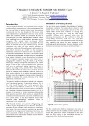
Sound Source Localisation with Acoustic Mirrors<br />
Martin Helfer<br />
Forschungsinstitut für Kraftfahrwesen und Fahrzeugmotoren Stuttgart, Germany<br />
e-mail:martin.helfer@fkfs.de<br />
Acoustic <strong>mirrors</strong>, also known as sound <strong>mirrors</strong>, have been<br />
used for sound source detection and localisation for many<br />
years even though they were not very common. Probably<br />
their first application took place on the military field as early<br />
warning systems for adversary aircraft. In recent years many<br />
of them have been used for sound source determination in<br />
rail and road transport. Especially in aero<strong>acoustic</strong> wind<br />
tunnels sound <strong>mirrors</strong> have become one of the preferred<br />
measurement techniques for the investigation of exterior<br />
sound radiation of vehicles and planes. One of their<br />
favourable properties is the simple setup which allows easy<br />
identification and estimation of the main sources without<br />
requiring extensive data processing. On the other hand a<br />
complete documentation of the radiated sound pattern may<br />
be quite time-consuming.<br />
2 Functional principle and configuration<br />
of <strong>acoustic</strong> <strong>mirrors</strong><br />
Acoustic <strong>mirrors</strong> consist of a paraboloid or ellipsoid mirror<br />
body with a microphone positioned at the focal point which<br />
records the sound reflected by the mirror surface. In case of<br />
paraboloid <strong>mirrors</strong> beams entering parallel to the mirror axis<br />
are registered (see fig. 1); in the case of ellipsoid <strong>mirrors</strong><br />
those beams are registered which emanate from the second<br />
focal point of the ellipsoid on the mirror axis (see fig. 2).<br />
Fig. 1: Function scheme of a paraboloid <strong>acoustic</strong> mirror [1]<br />
Fig. 2: Function scheme of an ellipsoid <strong>acoustic</strong> mirror [1]<br />
Owing to their use in communication technology paraboloid<br />
<strong>mirrors</strong> are more easily available than ellipsoid <strong>mirrors</strong><br />
which normally must be custom-built. Consequently,<br />
paraboloid <strong>mirrors</strong> are used most in the development of<br />
<strong>acoustic</strong> <strong>mirrors</strong> today. Their slightly poorer spatial<br />
resolution can in part be headed off by an ellipsoid-oriented<br />
positioning of the microphone.<br />
This requires first of all a precise determination of the shape<br />
of the selected mirror and the coefficient m in the mathematical<br />
equation of the underlying parabola<br />
y ⋅<br />
2<br />
= m x .<br />
The ideal microphone position (B) for a required measurement<br />
distance (position of the second focal point Q) can be<br />
determined according to fig. 3 by the equation<br />
2<br />
2<br />
a − mx<br />
b = mx + xtan(<br />
π − 2 arctan 2mx<br />
− arctan ) .<br />
x<br />
Fig. 3: Determination of microphone position in the<br />
<strong>acoustic</strong> mirror for a certain measuring distance, acc. to [1]<br />
As the equation shows, the result depends on the point of<br />
reflection on the mirror (x). Hence no single-valued result<br />
can be indicated for the microphone position. Due to the<br />
fact, however, that the number of reflected beams increases<br />
linearly with the distance from the mirror centre (x=0),<br />
determination of the optimal microphone position can be<br />
carried out by linear weighting of the calculated results over<br />
the parameter x. In this way a characteristic curve can be<br />
determined. It represents the relationship between the<br />
optimal distance of the microphone and the distance of the<br />
noise source from the apex of the parabolic mirror. An<br />
example is shown in fig. 4.<br />
Fig. 4: Relationship between measuring distance and<br />
microphone position (example) [1]<br />
3 Historical background<br />
Devices for amplifying and localising sound based on the<br />
principle of reflection have been known for centuries. As<br />
early as in the 2 nd century the Roman doctor Archigenes<br />
mentioned an ear trumpet against hardness of hearing and a<br />
miniature from the 12 th century shows King Arthur hunting
with an ear trumpet, which probably served to detect sound<br />
sources. The first person to describe this instrument was<br />
Athanasius Kircher in 1650, who is thus considered its<br />
inventor. In the 18 th and 19 th century ear trumpets existed in<br />
a variety of designs. Some of them were even integrated into<br />
furniture (armchairs). The last ear trumpet manufacturer, F.<br />
C. Rein & Son in London, shut down in 1963.<br />
The first technical applications go back to the 19 th century.<br />
The most famous of them is probably the 'topophone' of the<br />
American scientist Professor Alfred M. Mayer (1836-1897).<br />
Presented in 1880, this consisted essentially of two<br />
adjustable hearing cones. By regulating the distance of these<br />
cones from each other and their spatial orientation it was<br />
possible for sailors to identify the position of other ships' fog<br />
horns around them (see fig. 5).<br />
Fig. 5: Application of Alfred M. Mayer’s 'topophone' [2]<br />
In the 20 th century other systems were used for military<br />
purposes. One example is the sound locator of the German<br />
Armed Forces shown in fig. 6, which was used to localise<br />
enemy aircraft. Also the first real <strong>acoustic</strong> <strong>mirrors</strong> were<br />
developed as early warning systems for the detection of<br />
enemy airships or planes. They were set up in the years from<br />
about 1915 to 1930 along the south and east coast of<br />
England, consisting of a concave-shaped concrete body with<br />
an integrated listening device. Frequently this device<br />
consisted of a receiving funnel positioned at the focal point<br />
of the mirror. The sound was forwarded by means of pipes to<br />
a shelter nearby where it was monitored. Some applications<br />
also already used microphones.<br />
Fig. 6: Sound locator ('Ringrichtungshörer RRH' of the<br />
German Armed Forces (photo courtesy of Helge Fykse)<br />
Several of these concave mirror systems still exist and can<br />
be visited. As an example fig. 7 shows the mirror on the<br />
headland of Dungeness (county of Kent) which was<br />
probably already equipped with a microphone.<br />
Fig. 7: Acoustic mirror with a diameter of about 9 m on the<br />
headland of Dungeness in Kent (photo courtesy of Andrew<br />
Grantham)<br />
In vehicle <strong>acoustic</strong>s <strong>acoustic</strong> <strong>mirrors</strong> are nowadays mostly<br />
used for localising noise when measurements in proximity of<br />
the vehicle are too complicated or impossible. They are<br />
particularly well suited for use in aero<strong>acoustic</strong> wind tunnels<br />
with an open-jet test section for determination of exterior<br />
aerodynamic noise [1] (see fig. 8). For higher effectiveness<br />
these systems are often equipped with an additional video<br />
camera for observation of the measurement area and a<br />
positioning laser for precise adjustment of the device.<br />
Fig. 8: Acoustic mirror in an aero<strong>acoustic</strong> wind tunnel<br />
4 Properties<br />
Just like microphone arrays, <strong>acoustic</strong> <strong>mirrors</strong> have certain<br />
localisation and signal amplification properties. These<br />
depend on the distance from the test object as well as on the<br />
size and set-up of the measuring system. The larger the<br />
mirror diameter and the smaller the measuring distance, the<br />
more precise is in general the spatial resolution of the<br />
<strong>acoustic</strong> mirror. Moreover, the frequency of the measuring<br />
signal also plays an important role. Here, higher frequencies<br />
are advantageous for both the spatial resolution and signal<br />
amplification.<br />
For a point source with a certain frequency the <strong>acoustic</strong><br />
mirror shown on the left in fig. 9 measures the signal<br />
strength shown on the right when it propagates in xdirection.<br />
The position of the mimima above and below the<br />
major lobe can be determined [3] by the equation<br />
and<br />
λ<br />
α = 1 . <strong>22</strong> ⋅<br />
D<br />
sin min
= A⋅<br />
tanα<br />
or respectively<br />
min<br />
λ<br />
b ≈ A ⋅1<br />
. <strong>22</strong> ⋅<br />
(for b
5 Special designs<br />
For special applications array-based <strong>acoustic</strong> <strong>mirrors</strong><br />
prooved to be efficient in the recent years [1,7]. In these<br />
<strong>mirrors</strong> a number of closely spaced microphones (instead of<br />
just one) are positioned on a plane vertical to the mirror axis.<br />
As illustrated in fig. 14, each of these microphones is<br />
positioned at a special focal point corresponding to an ‘own’<br />
ellipsoid, of which the mirror constitutes a partial section.<br />
So, each of the microphones focuses, via this focal point, on<br />
its own measurement point on the test object (the second<br />
focus of the respective ellipsoid). This permits the<br />
simultaneous measurement of the radiation pattern of an<br />
entire surface without any need of traversing the <strong>acoustic</strong><br />
mirror. Fig. 15 shows the application of such a system in an<br />
aero<strong>acoustic</strong> wind tunnel.<br />
Fig. 14: Function scheme of an array-based <strong>acoustic</strong> mirror<br />
Fig. 15: Application of an array-based <strong>acoustic</strong> mirror in an<br />
aero<strong>acoustic</strong> wind tunnel (photo courtesy of Daimler AG)<br />
6 Examples of use<br />
Acoustic <strong>mirrors</strong> are primarily used in wind tunnels with<br />
open-jet test section. The first objects to be tested came from<br />
aerospace research [4,5]. Later, also investigations on rail<br />
vehicles (e.g. pantographs [7]) and road vehicles were<br />
carried out [1]. As an example fig. 16 shows the<br />
aerodynamic sound source distribution of a vehicle in a wind<br />
tunnel. However, <strong>acoustic</strong> <strong>mirrors</strong> have also been used for in<br />
situ measurements of traffic noise. Some of the array-based<br />
versions, for example, have prooved to be very effective to<br />
localise noise sources of passing trains [6].<br />
Acoustic <strong>mirrors</strong> can also be used to advantage when it is<br />
not necessary to record the overall sound source distribution.<br />
For example, individual vehicle sections can already be<br />
<strong>acoustic</strong>ally optimised in wind tunnels, when it is not yet<br />
possible to carry out interior sound measurements (e.g. in the<br />
model phase). The a-pillars or windshield wipers, for<br />
example, can be <strong>acoustic</strong>ally assessed by carrying out<br />
measurements with an <strong>acoustic</strong> mirror positioned above the<br />
vehicle measuring only two to three radiation points on the<br />
appropriate device in each case.<br />
Fig. 16: Sound radiation pattern of a vehicle in an aero<strong>acoustic</strong><br />
wind tunnel for the 2.5 kHz third octave band [1]<br />
5 References<br />
[1] Helfer, M.: Hohlspiegelmikrofone. Workshop 'Mess-<br />
und Analysetechnik in der Fahrzeugakustik', <strong>09</strong>.-<br />
10.10.2007, at <strong>FKFS</strong> in Stuttgart<br />
[2] N.N.: Appareil acoustique pour reconnaître en mer le<br />
lieu de production d’un son. La Nature, no. 391,<br />
27.11.1880, p. 401<br />
[3] Sommerfeld, A.: Vorlesungen über theoretische Physik<br />
- Bd. IV: Optik. Frankfurt: Harry Deutsch Verlag,<br />
1989, ISBN 978-3871443770<br />
[4] Grosche, F.-R.; Stiewitt, H.; Binder, B.: Sound Source<br />
Location and Discrimination from Background Noise<br />
in Wind-Tunnel Tests. International Congress on<br />
Instrumentation in Aerospace Simulation Facilities<br />
(ICIASF’75), Ottawa (CDN), <strong>22</strong>.-24.<strong>09</strong>.1975<br />
[5] Grosche, F.-R.; Jones, J. H.; Wilhold, G. A.:<br />
Measurement of the Distribution of Sound Source<br />
Intensities in Turbulent Jets. In: Duct Acoustics<br />
(Progress in Astronautics and Aeronautics, Vol. 37,<br />
AIAA, 1975), pp. 79-92<br />
[6] Grosche, F.-R.: Application Possibilities of Acoustic<br />
Mirrors for Noise Source Localization. DGLR Workshop<br />
on the Aero<strong>acoustic</strong>s of Cars, 16.-17.11.1992 at<br />
DNW in Noordoostpolder, The Netherlands<br />
[7] Grosche, F.-R.: Source Location and Investigation of<br />
Aerodynamic Sound Sources by the Elliptic-Mirror-<br />
Microphone System in the DNW and other Wind<br />
Tunnels. First CEAS-ASC Workshop on Wind Tunnel<br />
Testing in Aero<strong>acoustic</strong>s, 05-06.11.1997 at DNW in<br />
Noordoostpolder, The Netherlands<br />
[8] Helfer, M.: Beurteilung von Hohlspiegelmikrofonen<br />
zur Schallquellenortung. In: Ahmed, S. R.: Akustik und<br />
Aerodynamik des Kraftfahrzeugs. Renningen: Expert-<br />
Verlag, 1994. ISBN 3-8169-1190-0