

YVAA Style A Air-Cooled Screw Liquid Chillers ... - Johnson Controls
YVAA Style A Air-Cooled Screw Liquid Chillers ... - Johnson Controls
YVAA Style A Air-Cooled Screw Liquid Chillers ... - Johnson Controls

You also want an ePaper? Increase the reach of your titles
YUMPU automatically turns print PDFs into web optimized ePapers that Google loves.
FORM 201.28-NM1.1<br />
SECTION 5 - TECHNICAL DATA<br />
ISSUE DATE: 8/29/2012<br />
CTION 5 - TECHNICAL DATA FORM_201.28-NM1.1.EN (1106)<br />
weight 78<br />
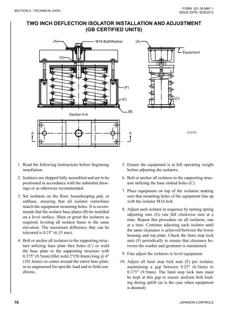
TWO INCH DEFLECTION ISOLATOR INSTALLATION AND ADJUSTMENT<br />
(GB CERTIFIED UNITS)<br />
TWO INCH DEFLECTION ISOLATOR INSTALLATION AND ADJUSTMENT<br />
(A)<br />
(G)<br />
Section A-A<br />
M16<br />
M16 Bolt/Washer<br />
Bolt/Washer<br />
A AA<br />
1. Read the following instructions before beginning<br />
installation.<br />
1. Read the following instructions before beginning<br />
installation.<br />
2. Isolators 2. Isolators are shipped are shipped fully fully assembled assembled and and are are to to be be<br />
positioned positioned in accordance in accordance with with the the submittal draw- draw-<br />
ings or as ings otherwise or as otherwise recommended.<br />
3. Set isolators on the floor, housekeeping pad, or<br />
subbase, ensuring that all isolator centerlines<br />
match the equipment mounting holes. It is recommends<br />
that the isolator base plates (B) be installed<br />
on a level surface. Shim or grout the isolators as<br />
required, leveling all isolator bases to the same<br />
elevation. The maximum difference that can be<br />
tolerated is 0.25" (6.35 mm).<br />
3. Set isolators on floor, housekeeping pad, or subbase,<br />
ensuring that all isolator centerlines match<br />
the equipment mounting holes. It is recommends<br />
that the isolator base plates (B) be installed on a<br />
level surface. Shim or grout as required, leveling<br />
all isolator base plates to the same elevation<br />
(0.25"(6.35mm) maximum difference can be<br />
tolerated).<br />
4. Bolt or anchor all isolators to the supporting structure<br />
utilizing base plate thru holes (C) or weld<br />
the base plate to the supporting structure with<br />
0.375" (9.5mm) fillet weld 2"(50.8mm) long @ 4"<br />
(101.6mm) on center around the entire base plate;<br />
or as engineered for specific load and or field conditions.<br />
4. Bolt or anchor all isolators to supporting structure<br />
utilizing base plate thru holes (C) or weld base<br />
plate to supporting structure with 0.375"(9.5mm)<br />
fillet weld 2"(50.8mm) long @ 4"(101.6mm) on<br />
centre around entire base plate or as engineered<br />
for specific load and or field conditions.<br />
5. The adjustment process can only begin after the<br />
equipment or machine is at its full operating<br />
6. Bolt or anchor all isolators to supporting structure<br />
(F)<br />
(C)<br />
(B)<br />
(A)<br />
(C)<br />
Equipment<br />
LD16183<br />
.<br />
7. Place equipment on top of isolators making sure<br />
that mounting holes of the equipment line up with<br />
5. Ensure the equipment is at full operating weight<br />
before adjusting the isolators.<br />
6. Bolt isolator or anchor M16 all bolt. isolators to the supporting structure<br />
utilizing the base slotted holes (C).<br />
8. Adjust each isolator in sequence by turning spring<br />
adjusting nuts (G) one full clockwise turn at a<br />
time. Repeat this procedure on all isolators, one<br />
at a time. Continue adjusting each isolator until<br />
same clearance is achieved between the lower<br />
housing and top plate. Check the limit stop lock<br />
nuts (F) periodically to ensure that clearance<br />
between the washer and grommet is maintained.<br />
7. Place equipment on top of the isolators making<br />
sure that mounting holes of the equipment line up<br />
with the isolator M16 bolt.<br />
8. Adjust each isolator in sequence by turning spring<br />
adjusting nuts (G) one full clockwise turn at a<br />
time. Repeat this procedure on all isolators, one<br />
at a time. Continue adjusting each isolator until<br />
the same clearance is achieved between the lower<br />
housing and top plate. Check the limit stop lock<br />
8. Fine adjust isolators to level equipment.<br />
nuts (F) periodically to ensure that clearance between<br />
the washer and grommet is maintained.<br />
9. Adjust all limit stop lock nuts (F) per isolator,<br />
maintaining 0.25"(6.3mm) to 0.375"(9.5mm) gap.<br />
The limit stop nuts must be kept at this gap to<br />
ensure uniform bolt loading during uplift (as the<br />
9. Fine adjust the isolators to level equipment.<br />
10. Adjust all limit stop lock nuts (F) per isolator,<br />
maintaining a gap between 0.25" (6.3mm) to<br />
0.375" case when (9.5mm). equipment The limit is stop drained) lock nuts must<br />
be kept at this gap to ensure uniform bolt loading<br />
during uplift (as is the case when equipment<br />
is drained)<br />
JOHNSON CONTROLS


