SUNNY ISLAND 5048 - Technical Description - Wind & Sun Ltd.
SUNNY ISLAND 5048 - Technical Description - Wind & Sun Ltd.
SUNNY ISLAND 5048 - Technical Description - Wind & Sun Ltd.

Create successful ePaper yourself
Turn your PDF publications into a flip-book with our unique Google optimized e-Paper software.
Electrical Connection SMA Solar Technology AG<br />
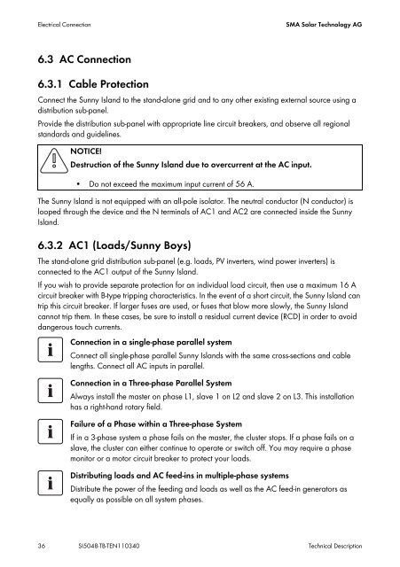
6.3 AC Connection<br />
6.3.1 Cable Protection<br />
Connect the <strong>Sun</strong>ny Island to the stand-alone grid and to any other existing external source using a<br />
distribution sub-panel.<br />
Provide the distribution sub-panel with appropriate line circuit breakers, and observe all regional<br />
standards and guidelines.<br />
NOTICE!<br />
Destruction of the <strong>Sun</strong>ny Island due to overcurrent at the AC input.<br />
• Do not exceed the maximum input current of 56 A.<br />
The <strong>Sun</strong>ny Island is not equipped with an all-pole isolator. The neutral conductor (N conductor) is<br />
looped through the device and the N terminals of AC1 and AC2 are connected inside the <strong>Sun</strong>ny<br />
Island.<br />
6.3.2 AC1 (Loads/<strong>Sun</strong>ny Boys)<br />
The stand-alone grid distribution sub-panel (e.g. loads, PV inverters, wind power inverters) is<br />
connected to the AC1 output of the <strong>Sun</strong>ny Island.<br />
If you wish to provide separate protection for an individual load circuit, then use a maximum 16 A<br />
circuit breaker with B-type tripping characteristics. In the event of a short circuit, the <strong>Sun</strong>ny Island can<br />
trip this circuit breaker. If larger fuses are used, or fuses that blow more slowly, the <strong>Sun</strong>ny Island<br />
cannot trip them. In these cases, be sure to install a residual current device (RCD) in order to avoid<br />
dangerous touch currents.<br />
Connection in a single-phase parallel system<br />
Connect all single-phase parallel <strong>Sun</strong>ny Islands with the same cross-sections and cable<br />
lengths. Connect all AC inputs in parallel.<br />
Connection in a Three-phase Parallel System<br />
Always install the master on phase L1, slave 1 on L2 and slave 2 on L3. This installation<br />
has a right-hand rotary field.<br />
Failure of a Phase within a Three-phase System<br />
If in a 3-phase system a phase fails on the master, the cluster stops. If a phase fails on a<br />
slave, the cluster can either continue to operate or switch off. You may require a phase<br />
monitor or a motor circuit breaker to protect your loads.<br />
Distributing loads and AC feed-ins in multiple-phase systems<br />
Distribute the power of the feeding and loads as well as the AC feed-in generators as<br />
equally as possible on all system phases.<br />
36 SI<strong>5048</strong>-TB-TEN110340 <strong>Technical</strong> <strong>Description</strong>