
You also want an ePaper? Increase the reach of your titles
YUMPU automatically turns print PDFs into web optimized ePapers that Google loves.
8 © 2008<br />
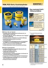
<strong>Swing</strong> <strong>cylinders</strong><br />
<strong>Swing</strong> Cylinders<br />
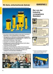
<strong>Enerpac</strong>’s complete line of swing <strong>cylinders</strong> provide<br />
maximum clamping force in the smallest possible<br />
package. With several mounting and operation styles<br />
available, <strong>Enerpac</strong> can fi t any clamping need you<br />
can think of. Our unique patented clamp arm design<br />
is an industry exclusive, and makes <strong>Enerpac</strong>’s swing<br />
cylinder line more versatile than ever before. Made<br />
to the highest quality standards, <strong>Enerpac</strong> swing<br />
<strong>cylinders</strong> will provide maximum performance and<br />
trouble free operation.<br />
Work Supports<br />
<strong>Enerpac</strong>’s line of work support <strong>cylinders</strong> gives you<br />
maximum holding force in a compact package.<br />
Incorporating innovative material combinations,<br />
our work supports feature the lowest lock-up<br />
pressures in the industry. Also, the use of corrosion<br />
resistant materials enables <strong>Enerpac</strong> work supports<br />
to stand up time and time again to even the most<br />
abrasive applications.<br />
Technical support<br />
Refer to the “Yellow Pages”<br />
of this catalog for:<br />
Safety instructions<br />
Basic hydraulic information<br />
Advanced hydraulic technology<br />
FMS (Flexible Machining Systems)<br />
technology<br />
Conversion charts and hydraulic symbols<br />
161 �<br />
www.enerpac.com
& Work supports<br />
<strong>Swing</strong> cylinder range overview<br />
Upper fl ange swing <strong>cylinders</strong><br />
Lower fl ange swing <strong>cylinders</strong><br />
Threaded body swing <strong>cylinders</strong><br />
Cartridge model swing <strong>cylinders</strong><br />
Additional swing <strong>cylinders</strong><br />
Positive locking swing <strong>cylinders</strong> [Collet-Lok ® ]<br />
Clamp arms<br />
Pivoting T-arms<br />
Upreach clamp arms<br />
Work support range overview<br />
Hydraulic advance work supports<br />
Spring advance work supports<br />
Positive locking work supports [Collet-Lok ® ]<br />
Work support mounting dimensions<br />
▼ series ▼ page<br />
SU<br />
SL<br />
ST<br />
SC<br />
SC, ASC<br />
WTR<br />
WP<br />
CA<br />
CAC<br />
CAPT<br />
CAU<br />
WF<br />
WS<br />
WP<br />
WF, WS<br />
10 - 11<br />
10 12 - 13 11<br />
14 - 15<br />
16 - 17<br />
18 - 19<br />
20 - 23<br />
24 - 25<br />
26 - 27<br />
28 - 29<br />
30 - 31<br />
32 - 33<br />
34 - 35<br />
36 - 37<br />
38 - 39<br />
40 - 41<br />
© 2008 9<br />
C<br />
D<br />
A<br />
B
<strong>Swing</strong> <strong>cylinders</strong><br />
Work supports<br />
98-037<br />
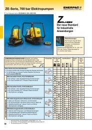
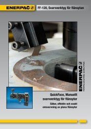
<strong>Swing</strong> <strong>cylinders</strong> Application & selection<br />
Shown: SCRD-122, STLD-21, WPFL-50<br />
<strong>Enerpac</strong> swing <strong>cylinders</strong> allow unobstructed<br />
part fi xturing and placement. The plunger rod and<br />
the attached clamp arm rotate 90 degrees in either a<br />
clockwise or counter-clockwise direction, then travel<br />
down an additional distance to clamp against the<br />
fi xtured part. Upon release of clamping pressure,<br />
the clamp arm rotates back 90 degrees in the<br />
opposite direction to allow for part removal<br />
and new part placement.<br />
Roller in groove<br />
Double index provides low height<br />
design to minimize fi xture height<br />
Overload clutch allows clamp to<br />
disengage if needed to prevent<br />
damage due to improper<br />
part loading<br />
Ball in groove<br />
Rotation direction can be changed<br />
on-site to reduce spare inventory<br />
by 2/3 (67%)<br />
Ball and cam rotation ensures<br />
smooth accurate operation<br />
❚ <strong>Swing</strong> <strong>cylinders</strong> used in conjunction with work supports<br />
and other <strong>Enerpac</strong> components to positively hold the<br />
workpieces during machining operations.<br />
98-001<br />
Compact and full featured design<br />
Compact design allows for effi cient fi xture layout<br />
Variety of mounting styles to meet design needs<br />
Double and single-acting <strong>cylinders</strong> to suit a variety<br />
of hydraulic requirements<br />
Choice of porting styles to meet system and<br />
design requirements<br />
All <strong>cylinders</strong> are available as left and right turning models<br />
Large ball and cam design on 21, 51 and 121 models allows<br />
swing rotation to be changed easily<br />
Kick-out mechanism on 92, 201, and 351 models prevents<br />
damage to cylinder from high fl ow rates or misapplication<br />
Select your swing cylinder type:<br />
Single acting<br />
The obvious choice when there<br />
are few system restrictions, and<br />
there are not many units retracting<br />
simultaneously<br />
Fewer valving requirements which<br />
results in a less complex circuit<br />
Innovative clamp arm design allows<br />
quick and secure arm positioning<br />
Double acting<br />
Used when greater control is required<br />
during the unclamp cycle<br />
When timing sequences are critical:<br />
less sensitive to system back<br />
pressures, resulting from long tube<br />
lengths or numerous components<br />
being retracted at the same time<br />
Innovative clamp arm design allows<br />
quick and secure arm positioning<br />
Collet-Lok ® positive locking<br />
<strong>Enerpac</strong> Collet-Lok ® positive<br />
locking <strong>cylinders</strong> are designed to<br />
mechanically hold the workpiece<br />
while hydraulic pressure is removed.<br />
After machining, hydraulic pressure<br />
is applied to unclamp the workpiece<br />
Used when live hydraulics are not<br />
available during the clamp cycle or<br />
when parts must be held for long<br />
periods of time<br />
This design is an industry exclusive<br />
For Collet-Lok ® positive locking<br />
swing <strong>cylinders</strong>, see 24 �<br />
10<br />
© 2008<br />
www.enerpac.com
Select your mounting method:<br />
SU series, Upper fl ange mounting<br />
Flexible design allows for manifold or<br />
threaded oil port connection<br />
Fixture hole does not require tight tolerances<br />
Easy installation with only 3 or 4 mounting bolts<br />
SL series, Lower fl ange mounting<br />
Flexible design allows for manifold<br />
or threaded port connection<br />
No fi xture hole required<br />
Easy installation with only 3 or 4 mounting bolts<br />
ST series, Threaded body mounting<br />
Body thread for precise cylinder height positioning<br />
Threaded oil port connection<br />
Can be threaded directly into the fi xture and secured<br />
in position by means of standard fl ange nuts<br />
SC series, Cartridge mounting<br />
Minimal space required on fi xture<br />
External plumbing not required<br />
Allows close positioning of adjoining units<br />
Cylinder can be completely recessed in fi xture<br />
Product selection<br />
12 �<br />
14 �<br />
16 �<br />
18 �<br />
Clamping Stroke Upper fl ange Lower fl ange Threaded body Cartridge<br />
force 1)<br />
in<br />
lbs clamping total<br />
▼ Single acting Model number 2)<br />
475 .32 .65 SURS-21 SLRS-21 STRS-21 SCRS-22<br />
1100 .39 .89 SURS-51 SLRS-51 STRS-51 SCRS-52<br />
1800 .47 .87 SURS-92 SLRS-92 STRS-92 –<br />
2400 .50 1.12 SURS-121 SLRS-121 STRS-121 SCRS-122<br />
3900 .55 1.10 SURS-201 SLRS-201 STRS-201 –<br />
7450 .63 1.18 SURS-351 SLRS-351 STRS-351 –<br />
▼ Double acting Model number2) ▼ Collet Lok ® positive locking Model number2) 500 .32 .65 SURD-21 SLRD-21 STRD-21 SCRD-22<br />
1250 .39 .89 SURD-51 SLRD-51 STRD-51 SCRD-52<br />
2025 .47 .87 SURD-92 SLRD-92 STRD-92 –<br />
2025 1.26 1.65 SURDL-92* – – –<br />
2600 .50 1.12 SURD-121 SLRD-121 STRD-121 SCRD-122<br />
2600 1.25 1.87 SURDL-121 – – –<br />
4200 .55 1.10 SURD-201 SLRD-201 STRD-201 –<br />
7600 .63 1.18 SURD-351 SLRD-351 STRD-351 –<br />
7600 1.25 1.83 SURDL-351* – – –<br />
1000 .32 .94 – WPFR-50 – –<br />
2000 .47 1.10 – WPFR-100 WPTR-100 –<br />
8500 .39 1.65 – WPFR-300* WPTR-300* –<br />
1) With standard clamp arm. Clamp arms are sold separately ( 26). Clamping forces for single-acting models are reduced<br />
in order to overcome return spring force. 2) For left turning swing <strong>cylinders</strong> replace the R in the model number<br />
for an L. Note: Call <strong>Enerpac</strong> to order models with metric thread and BSPP port connections.<br />
* This product is made to order. Please contact <strong>Enerpac</strong> for delivery information before specifying in your design.<br />
<strong>Swing</strong> <strong>cylinders</strong><br />
Force: 500 - 8500 lbs<br />
Stroke: .32 - 1.87 inch<br />
Pressure: 500 - 5000 psi<br />
E Cilindros giratorios<br />
F Vérins de bridage pivotants<br />
D Schwenkspannzylinder<br />
Options<br />
Available as<br />
both left and<br />
right turning<br />
Clamp arms<br />
26 �<br />
Work supports<br />
Accessories<br />
32 �<br />
78 �<br />
Important<br />
3<br />
2<br />
1<br />
4<br />
Left Right<br />
90°<br />
Actual clamping may only<br />
take place when the cylinder<br />
has completed its 90° swing.<br />
Clamping<br />
Total stroke<br />
All swing <strong>cylinders</strong> have swing<br />
angle repeatability<br />
of ± 1°.<br />
Other swing angles available<br />
upon request.<br />
Contact <strong>Enerpac</strong> for info.<br />
11<br />
<strong>Swing</strong> <strong>cylinders</strong><br />
Work supports<br />
Linear <strong>cylinders</strong> Power sources Valves<br />
System<br />
components<br />
Yellow pages
<strong>Swing</strong> <strong>cylinders</strong><br />
Work supports<br />
98-038<br />
98-003<br />
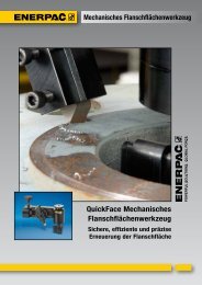
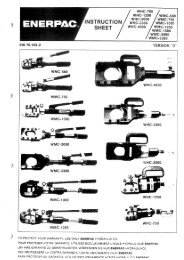
<strong>Swing</strong> <strong>cylinders</strong> - Upper fl ange model<br />
Shown: SURS-201, SURS-51<br />
12<br />
SU series<br />
The <strong>Enerpac</strong> upper fl ange<br />
swing <strong>cylinders</strong> are designed for<br />
integrated manifold mounting<br />
solutions. Hydraulic connections<br />
are made through SAE or BSPP<br />
oil connection or the standard<br />
integrated O-ring ports.<br />
SAE oil connection<br />
Integrated O-ring port<br />
❚ <strong>Enerpac</strong> upper fl ange swing<br />
clamps integrated into a fully<br />
automated machining system.<br />
Minimal mounting height<br />
…when space is at a premium<br />
Flexible design allows for manifold or threaded port connection<br />
Low profi le mounting style allows body to be below mounting surface<br />
Simple mounting preparation and easy installation – 3 or 4 mounting bolts<br />
Double oil connection – threaded port or manifold mount<br />
Symmetrical rectangular fl ange design enables clamping<br />
at three sides of the cylinder<br />
30, 45, and 60 degree swing angles available on request<br />
Left<br />
turning<br />
models<br />
Product selection<br />
Clamping Stroke Left Right Cylinder Oil Max. Standard<br />
force1) turning turning effective area capacity oil clamp arm<br />
fl ow 1)<br />
in in2 in3 Sold<br />
Un- Un- separately<br />
lbs Clamp Total Clamp clamp Clamp clamp in3 /min 22 �<br />
▼ Single acting Model number 2)<br />
▼ Double acting Model number 2)<br />
90° 90°<br />
475 .32 .65 SULS-21 SURS-21 .12 – .08 – 12 CAS-21<br />
1100 .39 .89 SULS-51 SURS-51 .28 – .25 – 25 CAS-51<br />
1800 .47 .87 SULS-92 SURS-92 .49 – .42 – 60 CAS-92<br />
2400 .50 1.12 SULS-121 SURS-121 .63 – .70 – 100 CAS-121<br />
3900 .55 1.10 SULS-201 SURS-201 1.10 – 1.22 – 140 CAS-201<br />
7450 .63 1.18 SULS-351 SURS-351 1.92 – 2.27 – 240 CAS-351<br />
500 .32 .65 SULD-21 SURD-21 .12 .24 .08 .16 12 CAS-21<br />
1250 .39 .89 SULD-51 SURD-51 .28 .59 .25 .53 25 CAS-51<br />
2025 .47 .87 SULD-92 SURD-92 .49 1.25 .42 1.08 60 CAS-92<br />
2025 1.26 1.65 SULDL-92* SURDL-92* .49 1.25 .81 1.86 60 CAS-92<br />
2600 .50 1.12 SULD-121 SURD-121 .63 1.23 .70 1.40 100 CAS-121<br />
2600 1.25 1.87 SULDL-121 SURDL-121 .63 1.23 .97 2.30 100 CAS-121<br />
4200 .55 1.10 SULD-201 SURD-201 1.10 2.35 1.22 2.60 140 CAS-201<br />
7600 .63 1.18 SULD-351 SURD-351 1.92 3.68 2.27 4.35 240 CAS-351<br />
7600 1.25 1.83 SULDL-351* SURDL-351* 1.92 3.68 3.53 6.77 240 CAS-351<br />
1) With standard clamp arm. Clamp arms are sold separately ( 26). Clamping forces<br />
for single-acting models are reduced in order to overcome return spring force.<br />
2) For models with straight plunger movement, replace L or R with S.<br />
* This product is made to order. Please contact <strong>Enerpac</strong> for delivery information<br />
before specifying in your design.<br />
Note: Call <strong>Enerpac</strong> to order<br />
models with BSPP port<br />
connections.<br />
Dimensions in inches [ ]<br />
A B C C1 D D1 D2 F H K M<br />
Ø Ø<br />
▼ Single acting<br />
SULS-21 4.41 2.32 1.04 1.69 1.10 1.86 1.77 .39 .43 .63 –<br />
SULS-51 5.31 2.71 1.08 1.97 1.37 2.13 2.25 .63 .39 .75 –<br />
SULS-92 5.67 3.00 1.10 1.97 1.88 2.76 2.13 .98 .51 .98 .61<br />
SULS-121 6.75 3.37 1.06 2.18 1.87 2.63 2.88 .87 .39 1.19 –<br />
SULS-201 6.57 3.46 1.10 2.20 2.46 3.35 2.76 1.26 .51 1.18 .93<br />
SULS-351 7.46 3.97 1.10 2.28 3.02 3.94 3.50 1.50 .51 1.58 1.10<br />
▼ Double acting<br />
SULD-21 4.41 2.32 1.04 1.69 1.10 1.86 1.77 .39 .43 .63 –<br />
SULD-51 5.31 2.71 1.08 1.97 1.37 2.13 2.25 .63 .39 .7 5 –<br />
SULD-92 5.67 3.00 1.10 1.97 1.88 2.76 2.13 .98 .51 .98 –<br />
SULDL-92* 7.24 3.78 1.10 2.75 1.88 2.76 2.13 .98 .51 .98 –<br />
SULD-121 6.75 3.37 1.06 2.18 1.87 2.63 2.88 .87 .39 1.19 –<br />
SULDL-121 9.00 4.12 1.06 2.93 1.87 2.62 2.88 .87 .39 1.19 –<br />
SULD-201 6.56 3.45 1.10 2.20 2.46 3.35 2.76 1.26 .51 1.18 –<br />
SULD-351 7.45 3.96 1.10 2.28 3.02 3.94 3.50 1.50 .51 1.58 –<br />
SULDL-351* 8.69 4.58 1.10 2.93 3.02 3.94 3.50 1.50 .51 1.58 –<br />
NOTE: dimensions shown with standard clamp arm.<br />
* This product is made to order. Please contact <strong>Enerpac</strong> for delivery information before specifying in your design.<br />
www.enerpac.com
A<br />
B<br />
Installation dimensions in inches<br />
Clamping Fixture Mounting Min. Manifold O-ring 2)<br />
force 1) hole thread depth ARP number or<br />
lbs Ø D3 J UNF J2 inside Ø x thickness<br />
500 1.110 #10-32 .65 568-010<br />
1250 1.380 .250-28 .65 568-011<br />
2025 1.895 M6 .59 .17 x .139<br />
2600 1.880 .312-24 .80 568-011<br />
4200 2.475 .312-24 .67 .17 x .139<br />
7600 3.035 .375-24 .74 .17 x .139<br />
1) With standard clamp arm.<br />
2) Polyurethane, 92 Durometer<br />
-21, 51, 121<br />
D2<br />
U<br />
A<br />
= Clamping<br />
= Unclamping<br />
(venting)<br />
30˚<br />
60˚<br />
S<br />
W<br />
120˚<br />
(3x)<br />
H<br />
B<br />
A<br />
type 21 SAE #2<br />
51, 121 SAE #4<br />
1.00<br />
A<br />
B<br />
Q<br />
D1<br />
X<br />
F<br />
D<br />
Note: Mounting bolts and<br />
O-rings included.<br />
N<br />
V<br />
P<br />
K<br />
T<br />
B<br />
C1 C<br />
-92, 201, 351<br />
D2<br />
M<br />
A<br />
Dimensions & options SU series<br />
R<br />
type 92 G1/4"<br />
201, 351 SAE #4<br />
S<br />
W<br />
Manifold<br />
O-ring<br />
N P Q R S T U V W X<br />
UN ø lbs<br />
B<br />
A<br />
A<br />
B<br />
H<br />
V<br />
Q<br />
X<br />
D1<br />
F<br />
D<br />
U<br />
D3<br />
N<br />
J<br />
J2<br />
P T<br />
K<br />
C1<br />
B<br />
U<br />
Right<br />
turning<br />
models<br />
Single acting ▼<br />
.61 .96 .250-20 – 0.825 1.20 1.58 .225 2.09 0.714 1.0 SURS-21<br />
.75 1.58 .312-18 – 1.614 1.90 1.97 .268 2.60 0.565 2.5 SURS-51<br />
1.06 1.77 M10x1,5 1.02 0.934 2.20 1.65 .270 2.68 1.128 4.4 SURS-92<br />
1.00 2.00 .375-16 – 2.048 2.40 2.50 .347 3.38 0.717 3.5 SURS-121<br />
1.38 2.17 .500-13 1.02 1.145 2.80 2.16 .335 3.11 1.382 7.7 SURS-201<br />
1.75 2.68 .625-11 1.02 1.370 3.30 2.76 .425 3.48 1.634 12.1 SURS-351<br />
Double acting ▼<br />
.61 .96 .250-20 – 0.825 1.20 1.58 .225 2.09 0.714 1.0 SURD-21<br />
.75 1.58 .312-18 – 1.614 1.90 1.97 .268 2.60 0.565 2.5 SURD-51<br />
1.06 1.77 M10x1,5 1.02 0.934 2.20 1.65 .270 2.68 1.128 4.4 SURD-92<br />
1.06 2.00 M10x1,5 1.02 0.934 2.20 1.65 .270 3.46 1.128 5.7 SURDL-92*<br />
1.00 2.00 .375-16 – 2.048 2.40 2.50 .347 3.38 0.717 3.5 SURD-121<br />
1.00 2.00 .375-16 – 2.048 2.40 2.50 .347 4.88 0.717 4.0 SURDL-121<br />
1.38 2.17 .500-13 1.02 1.145 2.80 2.16 .335 3.11 1.382 7.7 SURD-201<br />
1.75 2.68 .625-11 1.02 1.370 3.30 2.76 .425 3.48 1.634 12.1 SURD-351<br />
1.75 2.68 .625-11 1.02 1.370 3.30 2.76 .425 4.11 1.634 15.1 SURDL-351*<br />
NOTE: U = bolt circle<br />
1.00<br />
63<br />
ø .19<br />
.004<br />
C<br />
Force: 500 - 7600 lbs<br />
Stroke: .32 - 1.87 inch<br />
Pressure: 500 - 5000 psi<br />
E Cilindros giratorios<br />
F Vérins de bridage pivotants<br />
D Schwenkspannzylinder<br />
Options<br />
Clamp arms<br />
26 �<br />
Work supports<br />
32 �<br />
Collet-Lok ®<br />
swing <strong>cylinders</strong><br />
Accessories<br />
24 �<br />
78 �<br />
Important<br />
30, 45, and 60 degree<br />
rotations are available upon<br />
request. Add -30, -45 or -60<br />
to end of standard model<br />
number to order directly<br />
from <strong>Enerpac</strong>. To order<br />
rotation limiter separately,<br />
see page 26.<br />
Custom <strong>cylinders</strong> including<br />
longer stroke lengths are<br />
available on request.<br />
In case there is a risk of<br />
machining coolants and<br />
debris being inhaled via<br />
the breather vent, it is<br />
recommended to pipe this<br />
port to an area outside the<br />
fi xture that is protected<br />
from machining coolants<br />
and debris.<br />
Do not exceed<br />
maximum fl ow rates.<br />
© 2008 13<br />
<strong>Swing</strong> <strong>cylinders</strong><br />
Work supports<br />
Linear <strong>cylinders</strong> Power sources Valves System<br />
components<br />
Yellow pages
<strong>Swing</strong> <strong>cylinders</strong><br />
Work supports<br />
98-039<br />
98-002<br />
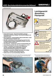
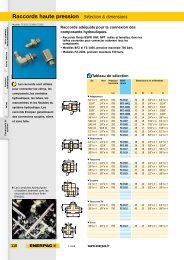
<strong>Swing</strong> <strong>cylinders</strong> - Lower fl ange models<br />
Shown: SLRD-51, SLRS-201<br />
14<br />
SL series<br />
<strong>Enerpac</strong> lower fl ange series swing<br />
<strong>cylinders</strong> can be bolted to the<br />
fi xture, allowing easy installation<br />
of the unit and does not require<br />
machined fi xture holes. Hydraulic<br />
connections are made through<br />
SAE or BSPP oil connection or the<br />
standard integrated O-ring ports.<br />
SAE oil connection<br />
Integrated O-ring port<br />
❚ Lower fl ange swing <strong>cylinders</strong><br />
mounted to the face of the fi xture.<br />
No fi xture hole required<br />
© 2008<br />
…cylinder can be bolted directly to fi xture<br />
Flexible design allows for manifold or threaded port connection<br />
No fi xture hole preparation required<br />
Easiest mounting preparation in the swing cylinder line<br />
Symmetrical rectangular fl ange design enables clamping at<br />
three sides of the cylinder<br />
Allows extra large parts to be clamped<br />
30, 45 and 60 degree swing angles available on request<br />
Product selection<br />
Clamping Stroke Left Right Cylinder Oil Max. Standard<br />
force1) turning turning effective area capacity oil clamp arm<br />
fl ow 1)<br />
in in2 in3 Sold<br />
Un- Un- separately<br />
lbs Clamp Total Clamp clamp Clamp clamp in3 90° 90°<br />
/min 26 �<br />
▼ Single acting Model number 2)<br />
475 .32 .65 SLLS-21 SLRS-21 .12 – .08 – 12 CAS-21<br />
1100 .39 .89 SLLS-51 SLRS-51 .28 – .25 – 25 CAS-51<br />
1800 .47 .87 SLLS-92 SLRS-92 .49 – .42 – 60 CAS-92<br />
2400 .50 1.12 SLLS-121 SLRS-121 .63 – .70 – 100 CAS-121<br />
3900 .55 1.10 SLLS-201 SLRS-201 1.10 – 1.22 – 140 CAS-201<br />
7450 .63 1.18 SLLS-351 SLRS-351 1.92 – 2.27 – 240 CAS-351<br />
▼ Double acting Model number 2)<br />
500 .32 .65 SLLD-21 SLRD-21 .12 .24 .08 .15 12 CAS-21<br />
1250 .39 .89 SLLD-51 SLRD-51 .28 .59 .25 .52 25 CAS-51<br />
2025 .47 .87 SLLD-92 SLRD-92 .49 1.25 .42 1.08 60 CAS-92<br />
2600 .50 1.12 SLLD-121 SLRD-121 .63 1.23 .70 1.40 100 CAS-121<br />
4200 .55 1.10 SLLD-201 SLRD-201 1.10 2.35 1.22 2.60 140 CAS-201<br />
7600 .63 1.18 SLLD-351 SLRD-351 1.92 3.68 2.27 4.35 240 CAS-351<br />
1) With standard clamp arm. Clamp arms are sold separately (26). Clamping forces<br />
for single-acting models are reduced in order to overcome return spring force.»<br />
2) For models with straight plunger movement, replace L or R with S.<br />
Left<br />
turning<br />
models<br />
Dimensions in inches [ ]<br />
▼ Single acting<br />
Note: Call <strong>Enerpac</strong> to order<br />
models with BSPP port<br />
connections.<br />
A C C1 D D1 D2 F H K M<br />
▼ Double acting<br />
SLLD-21 4.41 3.13 3.78 1.10 1.86 1.77 .39 .54 .63 –<br />
SLLD-51 5.31 3.68 4.57 1.37 2.13 2.25 .63 .55 .75 –<br />
SLLD-92 5.94 4.09 4.96 1.87 2.76 2.13 .98 .49 .98 –<br />
SLLD-121 6.75 4.44 5.56 1.87 2.63 2.88 .87 .62 1.19 –<br />
SLLD-201 6.88 4.48 5.63 2.51 3.35 2.76 1.26 .49 1.18 –<br />
SLLD-351 7.77 4.85 5.94 3.14 3.94 3.50 1.50 .49 1.58 –<br />
NOTE: dimensions shown with standard clamp arm.<br />
Ø Ø<br />
SLLS-21 4.41 3.13 3.78 1.10 1.86 1.77 .39 .54 .63 –<br />
SLLS-51 5.31 3.68 4.57 1.37 2.13 2.25 .63 .55 .75 –<br />
SLLS-92 5.94 4.09 4.96 1.88 2.76 2.13 .98 .49 .98 .61<br />
SLLS-121 6.75 4.44 5.56 1.87 2.63 2.88 .87 .62 1.19 –<br />
SLLS-201 6.88 4.48 5.63 2.51 3.35 2.76 1.26 .49 1.18 .93<br />
SLLS-351 7.77 4.85 5.94 3.14 3.94 3.50 1.50 .49 1.58 1.10<br />
www.enerpac.com
A<br />
B<br />
Installation dimensions in inches<br />
Clamping Mounting Minimum Manifold O-ring 2)<br />
force 1) thread thread depth ARP number or<br />
lbs J J2 inside Ø x thickness<br />
500 #10-32 .65 568-010<br />
1250 .250-28 .65 568-011<br />
2025 M6 .59 .17 x .139<br />
2600 .312-24 .80 568-011<br />
4200 .312-24 .67 .17 x .139<br />
7600 .375-24 .74 .17 x .139<br />
1) With standard clamp arm.<br />
2) Polyurethane, 92 Durometer<br />
-21, 51, 121<br />
120˚<br />
(3x) D1<br />
-92, 201, 351<br />
N<br />
V<br />
D2 U<br />
= Clamping<br />
= Unclamping<br />
(venting)<br />
30˚<br />
60˚<br />
H<br />
B<br />
A<br />
type 21 SAE #2<br />
51, 121 SAE #4<br />
.98<br />
S<br />
A<br />
B<br />
Q<br />
X<br />
Note: Mounting bolts and<br />
O-rings included.<br />
F<br />
D<br />
P<br />
T<br />
K<br />
C C1<br />
A<br />
D2<br />
Dimensions & options SL series<br />
R<br />
type 92 G1/4"<br />
201, 351 SAE #4<br />
S<br />
H<br />
Manifold<br />
O-ring<br />
N P Q R S T U V X<br />
B<br />
A<br />
A<br />
B<br />
D1<br />
V<br />
UN ø lbs<br />
Q<br />
X<br />
F<br />
D<br />
U<br />
N<br />
J<br />
P T<br />
K<br />
C<br />
U<br />
M<br />
A<br />
J2<br />
Right<br />
turning<br />
models<br />
Single acting ▼<br />
.61 .96 .250-20 – 0.825 1.22 1.58 .22 0.714 1.0 SLRS-21<br />
.75 1.58 .312-18 – 1.614 1.89 1.97 .27 0.565 2.5 SLRS-51<br />
1.06 1.77 M10x1,5 1.02 0.934 2.20 1.65 .27 1.128 4.4 SLRS-92<br />
1.00 2.00 .375-16 – 2.048 2.43 2.50 .35 0.717 3.5 SLRS-121<br />
1.38 2.17 .500-13 1.02 1.145 2.76 2.16 .33 1.382 7.7 SLRS-201<br />
1.75 2.68 .625-11 1.02 1.370 3.27 2.76 .42 1.634 12.1 SLRS-351<br />
Double acting ▼<br />
.61 .96 .250-20 – 0.825 1.22 1.58 .22 0.714 1.0 SLRD-21<br />
.75 1.58 .312-18 – 1.614 1.89 1.97 .27 0.565 2.5 SLRD-51<br />
1.06 1.77 M10x1,5 1.02 0.934 2.20 1.65 .27 1.128 4.4 SLRD-92<br />
1.00 2.00 .375-16 – 2.048 2.43 2.50 .35 0.717 3.5 SLRD-121<br />
1.38 2.17 .500-13 1.02 1.145 2.76 2.16 .33 1.382 7.7 SLRD-201<br />
1.75 2.68 .625-11 1.02 1.370 3.27 2.76 .42 1.634 12.1 SLRD-351<br />
NOTE: U = bolt circle<br />
.98<br />
63<br />
ø .19<br />
.004<br />
C1<br />
Force: 500 - 7600 lbs<br />
Stroke: .32 - 1.18 inch<br />
Pressure: 500 - 5000 psi<br />
E Cilindros giratorios<br />
F Vérins de bridage pivotants<br />
D Schwenkspannzylinder<br />
Options<br />
Clamp arms<br />
26 �<br />
Work supports<br />
32 �<br />
Collet-Lok ®<br />
swing <strong>cylinders</strong><br />
Accessories<br />
24 �<br />
78 �<br />
Important<br />
30, 45, and 60 degree<br />
rotations are available upon<br />
request. Add -30, -45 or -60<br />
to end of standard model<br />
number to order directly<br />
from <strong>Enerpac</strong>. To order<br />
rotation limiter separately,<br />
see page 26.<br />
Custom <strong>cylinders</strong> including<br />
longer stroke lengths are<br />
available on request.<br />
In case there is a risk of<br />
machining coolants and<br />
debris being inhaled via<br />
the breather vent, it is<br />
recommended to pipe this<br />
port to an area outside the<br />
fi xture that is protected<br />
from machining coolants<br />
and debris.<br />
Do not exceed<br />
maximum fl ow rates.<br />
© 2008 15<br />
<strong>Swing</strong> <strong>cylinders</strong><br />
Work supports<br />
Linear <strong>cylinders</strong> Power sources Valves System<br />
components<br />
Yellow pages
<strong>Swing</strong> <strong>cylinders</strong><br />
Work supports<br />
98-040<br />
98-014<br />
<strong>Swing</strong> <strong>cylinders</strong> - Threaded body models<br />
Shown: STRD-51, STRD-201<br />
16<br />
ST series<br />
<strong>Enerpac</strong> threaded body swing<br />
<strong>cylinders</strong> are threaded directly into<br />
the fi xture.<br />
The cylinder height is adjusted to<br />
the appropriate height, and then<br />
locked in place using a fl ange<br />
nut ( 78).<br />
SAE oil connection<br />
Flange nut<br />
❚ Threaded body swing <strong>cylinders</strong><br />
allow the clamp to be buried<br />
in the fi xture to minimize the<br />
required area, while the height<br />
remains adjustable.<br />
Cylinders can be threaded directly into fi xture<br />
© 2008<br />
…can be secured at any height<br />
Body thread for precise cylinder height positioning<br />
Threaded port connection<br />
Easy installation and removal<br />
Greatest fl exibility in fi xture design<br />
30, 45 and 60 degree swing angles available on request<br />
Product selection<br />
Clamping Stroke Left Right Cylinder Oil Max. Standard<br />
force1) turning turning effective area capacity oil clamp arm<br />
fl ow 1)<br />
in in2 in3 Sold<br />
Un- Un- separately<br />
lbs Clamp Total Clamp clamp Clamp clamp in3 90° 90°<br />
/min 26 �<br />
▼ Single acting Model number 2)<br />
475 .32 .65 STLS-21 STRS-21 .12 – .08 – 12 CAS-21<br />
1100 .39 .89 STLS-51 STRS-51 .28 – .25 – 25 CAS-51<br />
1800 .47 .87 STLS-92 STRS-92 .49 – .42 – 60 CAS-92<br />
2400 .50 1.12 STLS-121 STRS-121 .63 – .70 – 100 CAS-121<br />
3900 .55 1.10 STLS-201 STRS-201 1.10 – 1.22 – 140 CAS-201<br />
7450 .63 1.18 STLS-351 STRS-351 1.92 – 2.27 – 240 CAS-351<br />
▼ Double acting Model number 2)<br />
500 .32 .65 STLD-21 STRD-21 .12 .24 .08 .15 12 CAS-21<br />
1250 .39 .89 STLD-51 STRD-51 .28 .59 .25 .52 25 CAS-51<br />
2025 .47 .87 STLD-92 STRD-92 .49 1.25 .42 1.08 60 CAS-92<br />
2600 .50 1.12 STLD-121 STRD-121 .63 1.23 .70 1.40 100 CAS-121<br />
4200 .55 1.10 STLD-201 STRD-201 1.10 2.35 1.22 2.60 140 CAS-201<br />
7600 .63 1.18 STLD-351 STRD-351 1.92 3.68 2.27 4.35 240 CAS-351<br />
1) With standard clamp arm. Clamp arms are sold separately ( 26). Clamping forces<br />
for single-acting models are reduced in order to overcome return spring force.<br />
2) For models with straight plunger movement, replace L or R with S.<br />
Left<br />
turning<br />
models<br />
Dimensions in inches [ ]<br />
▼ Single acting<br />
Note: Call <strong>Enerpac</strong> to order<br />
models with BSPP<br />
port connections.<br />
A B C C1 C2 D D1 D2 F H J1<br />
Ø Ø<br />
STLS-21 4.41 2.32 1.04 1.69 .98 1.125-16 UNF 1.55 1.30 .39 .39 2.09<br />
STLS-51 5.31 2.71 1.08 1.97 .98 1.375-18 UNF 1.87 1.50 .63 .38 2.60<br />
STLS-92 5.67 3.20 1.30 2.17 1.18 M48 x 1,5 2.46 1.89 .98 .51 1.69<br />
STLS-121 6.75 3.37 1.06 2.18 1.00 1.875-16 UNF 2.38 2.00 .87 .38 3.38<br />
STLS-201 6.57 3.74 1.38 2.48 1.26 2.500-16 UNF 2.99 2.56 1.26 .51 2.06<br />
STLS-351 7.46 4.24 1.38 2.56 1.27 3.125-16 UNF 3.48 3.15 1.50 .51 2.57<br />
▼ Double acting<br />
STLD-21 4.41 2.32 1.04 1.69 .98 1.125-16 UNF 1.55 1.30 .39 .39 2.09<br />
STLD-51 5.31 2.71 1.08 1.97 .98 1.375-18 UNF 1.87 1.50 .63 .38 2.60<br />
STLD-92 5.67 3.20 1.30 2.17 1.18 M48 x 1,5 2.46 1.89 .98 .51 1.69<br />
STLD-121 6.75 3.37 1.06 2.18 1.00 1.875-16 UNF 2.38 2.00 .87 .38 3.38<br />
STLD-201 6.57 3.74 1.38 2.48 1.26 2.500-16 UNF 2.99 2.56 1.26 .51 2.06<br />
STLD-351 7.46 4.24 1.38 2.56 1.27 3.125-16 UNF 3.48 3.15 1.50 .51 2.57<br />
NOTE: dimensions shown with standard clamp arm.<br />
www.enerpac.com
A<br />
B<br />
Accessory Chart<br />
Model Nos. Mounting Flange<br />
Left Right fl ange nut<br />
turning turning<br />
90°<br />
Sold<br />
Separately<br />
Sold<br />
Separately<br />
79 78<br />
▼ Single acting<br />
STRS-21 STRS-21 — MF-281 FN-281<br />
STRS-51 STRS-51 AW-5 MF-351 FN-351<br />
STRS-92 STRS-92 — MF-482 FN-482<br />
STRS-121 STRS-121 AW-89 MF-481 FN-481<br />
STRS-201 STRS-201 AW-19 MF-651 FN-651<br />
STRS-351 STRS-351 AW-90 MF-801 FN-801<br />
▼ Double acting<br />
STRD-21 STRD-21 — MF-281 FN-281<br />
STRD-51 STRD-51 AW-5 MF-351 FN-351<br />
STRD-92 STRD-92 — MF-482 FN-482<br />
STRD-121 STRD-121 AW-89 MF-481 FN-481<br />
STRD-201 STRD-201 AW-19 MF-651 FN-651<br />
STRD-351 STRD-351 AW-90 MF-801 FN-801<br />
-21, 51, 121<br />
25˚ B<br />
D2 50˚<br />
A<br />
C2<br />
J1<br />
H<br />
A<br />
type 21 SAE #2<br />
51, 121 SAE #4<br />
K<br />
Q<br />
D1<br />
= Clamping<br />
= Unclamping (venting)<br />
F<br />
D<br />
N<br />
P<br />
T<br />
C<br />
B<br />
C1<br />
-92, 201, 351<br />
22,5˚<br />
D2 45˚<br />
type 92 G1/4"<br />
201, 351 SAE #4<br />
M<br />
K<br />
Q<br />
D1<br />
A C2<br />
F<br />
C<br />
H<br />
K M N P Q T W<br />
W<br />
J1<br />
B<br />
A<br />
D<br />
N<br />
P T<br />
B<br />
C1<br />
Right<br />
turning<br />
models<br />
Single acting ▼<br />
.63 – .61 .96 .250-20 unc 1.22 – 1.1 STRS-21<br />
.75 – .75 1.58 .312-18 unc 1.89 – 2.5 STRS-51<br />
.98 .61 .94 1.77 M10 x 1,5 2.20 2.48 4.4 STRS-92<br />
1.19 – 1.00 2.00 .375-16 unc 2.43 – 3.5 STRS-121<br />
1.18 .93 1.28 2.17 .500-13 unc 2.76 2.83 7.1 STRS-201<br />
Dimensions & options ST series<br />
1.58 1.10 1.57 2.68 .625-11 unc 3.27 3.21 12.1 STRS-351<br />
Double acting ▼<br />
.63 – .61 .96 .250-20 unc 1.22 – 1.1 STRD-21<br />
.75 – .75 1.58 .312-18 unc 1.89 – 2.5 STRD-51<br />
.98 – .94 1.77 M10 x 1,5 2.20 2.48 4.4 STRD-92<br />
1.19 – 1.00 2.00 .375-16 unc 2.43 – 3.5 STRD-121<br />
1.18 – 1.28 2.17 .500-13 unc 2.76 2.83 7.7 STRD-201<br />
1.58 – 1.57 2.68 .625-11 unc 3.27 3.21 12.1 STRD-351<br />
lbs<br />
Force: 500 - 7600 lbs<br />
Stroke: .32 - 1.18 inch<br />
Pressure: 500 - 5000 psi<br />
E Cilindros giratorios<br />
F Vérins de bridage pivotants<br />
D Schwenkspannzylinder<br />
Options<br />
Clamp arms<br />
26 �<br />
Work supports<br />
32 �<br />
Collet-Lok ®<br />
swing <strong>cylinders</strong><br />
Accessories<br />
24 �<br />
78 �<br />
Important<br />
30, 45, and 60 degree<br />
rotations are available upon<br />
request. Add -30, -45 or -60<br />
to end of standard model<br />
number to order directly<br />
from <strong>Enerpac</strong>. To order<br />
rotation limiter separately,<br />
see page 26.<br />
Custom <strong>cylinders</strong> including<br />
longer stroke lengths are<br />
available on request.<br />
In case there is a risk of<br />
machining coolants and<br />
debris being inhaled via<br />
the breather vent, it is<br />
recommended to pipe this<br />
port to an area outside the<br />
fi xture that is protected<br />
from machining coolants<br />
and debris.<br />
Do not exceed<br />
maximum fl ow rates.<br />
© 2008 17<br />
<strong>Swing</strong> <strong>cylinders</strong><br />
Work supports<br />
Linear <strong>cylinders</strong> Power sources Valves System<br />
components<br />
Yellow pages
<strong>Swing</strong> <strong>cylinders</strong><br />
Work supports<br />
98-041<br />
30007-4<br />
<strong>Swing</strong> <strong>cylinders</strong> - Cartridge models<br />
Shown: SCRD-122, SCRD-52<br />
SC series<br />
<strong>Enerpac</strong> cartridge swing <strong>cylinders</strong><br />
are designed for integrated<br />
manifold mounting. This eliminates<br />
the need for fi ttings and tubing on<br />
the fi xture.<br />
Cartridge swing <strong>cylinders</strong> simplify<br />
mounting and optimize clamping<br />
effectiveness.<br />
❚ Hydraulic fi xture with components<br />
on two faces for more effi cient<br />
production.<br />
18<br />
Eliminates the need for tubing and fi ttings<br />
© 2008<br />
… <strong>cylinders</strong> can be designed into narrow fi xture plates<br />
as thru-hole mounting is fully functional<br />
Minimal space required on fi xture<br />
Can be completely recessed in fi xture<br />
External plumbing not required<br />
Allows close positioning of adjoining units<br />
30, 45 and 60 degree swing angles available on request<br />
Product selection<br />
Clamping Stroke Left Right Cylinder Oil Max. Standard<br />
force1) turning turning effective area capacity oil<br />
fl ow<br />
clamp arm<br />
1)<br />
in in2 in3 Un- Un-<br />
Sold<br />
separately<br />
lbs Clamp Total Clamp clamp Clamp clamp in3 90°<br />
/min 26 �<br />
▼ Single acting Model number 2)<br />
▼ Double acting Model number 2)<br />
500 .32 .65 SCLD-22 SCRD-22 .12 .24 .08 .15 12 CAS-21<br />
1250 .39 .89 SCLD-52 SCRD-52 .28 .59 .25 .52 25 CAS-51<br />
2600 .50 1.12 SCLD-122 SCRD-122 .63 1.23 .70 1.40 100 CAS-121<br />
1) With standard clamp arm. Clamp arms are sold separately ( 26). Clamping forces for single-acting models are<br />
reduced in order to overcome return spring force.<br />
2) For models with straight plunger movement, replace L or R with S.<br />
Left<br />
turning<br />
models<br />
<strong>Enerpac</strong> compact design cartridge model swing <strong>cylinders</strong> used in conjunction<br />
with a cartridge model work support in a typical clamping application.<br />
475 .32 .65 SCLS-22 SCRS-22 .12 - .08 - 12 CAS-21<br />
1100 .39 .89 SCLS-52 SCRS-52 .28 - .25 - 25 CAS-51<br />
2400 .50 1.12 SCLS-122 SCRS-122 .63 - .70 - 100 CAS-121<br />
Dimensions in inches [ ]<br />
▼ Single acting<br />
A B C C1 C2 D1 D2 E F<br />
Ø Ø<br />
hexagon<br />
SCLS-22 4.41 2.18 .90 1.55 .84 1.50 1.00 1.38 .39<br />
SCLS-52 5.31 3.13 1.49 2.25 1.27 2.25 1.37 2.00 .63<br />
SCLS-122 6.75 3.69 1.38 2.50 1.32 3.00 2.25 2.75 .87<br />
▼ Double acting<br />
SCLD-22 4.41 2.18 .90 1.55 .84 1.50 1.00 1.38 .39<br />
SCLD-52 5.31 3.00 1.36 2.25 1.27 2.25 1.37 2.00 .63<br />
SCLD-122 6.75 3.69 1.38 2.50 1.32 3.00 2.25 2.75 .87<br />
NOTE: dimensions shown with standard clamp arm.<br />
www.enerpac.com
-22, 52, 122 models<br />
D1<br />
A<br />
C2<br />
W<br />
J1<br />
E<br />
øF<br />
Q<br />
øD2<br />
øJ<br />
P<br />
K<br />
C<br />
T<br />
B<br />
C1<br />
1.07-1.43<br />
1.88 min.**<br />
1.19-1.62<br />
2.00 min.**<br />
1.18-1.20<br />
1.62 min.**<br />
-22 models<br />
-52 models<br />
-122 models<br />
Dimensions & options SC series<br />
Installation dimensions<br />
in inches<br />
.05-.07<br />
R and Blend<br />
* Minimum plate height for single-acting models.<br />
** Minimum plate height for double-acting models.<br />
J J1 K P Q T W<br />
Right<br />
turning<br />
lbs models<br />
Single acting ▼<br />
M28 x 1,5 .59 .63 .96 .250-20 UNC 1.22 2.23 1.0 SCRS-22<br />
M42 x 1,5 .66 .75 1.58 .312-18 UNC 1.89 2.31 2.0 SCRS-52<br />
M60 x 1,5 .62 1.19 2.00 .375-16 UNC 2.43 2.94 5.5 SCRS-122<br />
Double acting ▼<br />
M28 x 1,5 .59 .63 .96 .250-20 UNC 1.22 2.23 1.0 SCRD-22<br />
M42 x 1,5 .66 .75 1.58 .312-18 UNC 1.89 2.31 2.0 SCRD-52<br />
M60 x 1,5 .62 1.19 2.00 .375-16 UNC 2.43 2.96 5.5 SCRD-122<br />
.62-.65<br />
.57-.59<br />
.54-.56<br />
ø.07-.09<br />
.08-.10<br />
ø.18-.20<br />
.11-.13<br />
ø.18-.20<br />
.15-.17<br />
ø1.51-1.53<br />
ø1.19-1.21<br />
M28 x 1,5<br />
30˚<br />
63<br />
20˚<br />
ø1.06-1.08<br />
ø2.26-2.28<br />
ø1.67-1.69<br />
M42 x 1,5<br />
30˚<br />
63<br />
20˚<br />
ø1.40-1.42<br />
ø3.01-3.03<br />
ø2.38-2.40<br />
M60 x 1,5<br />
30˚<br />
63<br />
20˚<br />
ø2.30-2.32<br />
63<br />
.05-.07<br />
.12 max<br />
ø1.000-1.002<br />
63<br />
.05-.07<br />
.12 max<br />
.08-.10<br />
ø1.375-1.377<br />
63<br />
.05-.07<br />
.12 max<br />
.08-.10<br />
ø2.250-2.252<br />
.68-.70<br />
1.00 min.*<br />
.70-.74<br />
1.00 min.*<br />
.64-.68<br />
1.00 min.*<br />
Force: 475 - 2600 lbs<br />
Stroke: .65 - 1.12 inch<br />
Pressure: 500 - 5000 psi<br />
E Cilindros giratorios<br />
F Vérins de bridage pivotants<br />
D Schwenkspannzylinder<br />
Options<br />
Clamp arms<br />
Accessories<br />
26 �<br />
Work supports<br />
32 �<br />
Collet-Lok ®<br />
swing <strong>cylinders</strong><br />
Sequence<br />
valves<br />
24 �<br />
78 �<br />
136 �<br />
Important<br />
30, 45, and 60 degree<br />
rotations are available upon<br />
request. Add -30, -45 or -60<br />
to end of standard model<br />
number to order directly<br />
from <strong>Enerpac</strong>. To order<br />
rotation limiter separately,<br />
see page 26.<br />
Custom <strong>cylinders</strong> including<br />
longer stroke lengths are<br />
available on request.<br />
In case there is a risk of<br />
machining coolants and<br />
debris being inhaled via<br />
the breather vent, it is<br />
recommended to pipe this<br />
port to an area outside the<br />
fi xture that is protected<br />
from machining coolants<br />
and debris.<br />
Do not exceed<br />
maximum fl ow rates.<br />
© 2008 19<br />
<strong>Swing</strong> <strong>cylinders</strong><br />
Work supports<br />
Linear <strong>cylinders</strong> Power sources Valves System<br />
components<br />
Yellow pages
<strong>Swing</strong> <strong>cylinders</strong><br />
Work supports<br />
99-083 <strong>Swing</strong><br />
<strong>cylinders</strong> SC series<br />
Shown: SC-3, SC-1<br />
SC series<br />
These swing <strong>cylinders</strong> rotate<br />
90˚ as they begin their stroke,<br />
continuing without rotation for the<br />
fi nal clamping stroke. Cylinders<br />
can be changed to left swing,<br />
right swing, or pull applications<br />
by loosening the side plug and<br />
then rotating the plunger to a<br />
desired position.<br />
The SC-1 and SC-3 include a<br />
retract spring for single-acting<br />
operation. Both <strong>cylinders</strong> can<br />
be operated as double-acting<br />
<strong>cylinders</strong> by connecting a retract<br />
line to the vent port.<br />
Model<br />
number<br />
20<br />
Changeable swing function<br />
A<br />
P<br />
B<br />
… with 360° fully adjustable clamp arm<br />
Changeable swing function: clamp arm<br />
movement can be adjusted to left or right<br />
swing, or straight pull function<br />
88-92° clamp arm swing arc<br />
Easy installation: built-in mountings<br />
and brackets<br />
Compact design for use in limited<br />
space applications<br />
Easy and precise locating of arm for<br />
clamp positioning<br />
Single or double-acting <strong>cylinders</strong> to suit<br />
variety of hydraulic requirements<br />
Selection chart<br />
Product dimensions in inches [ ]<br />
Clamping Stroke Model Cylinder Oil<br />
force 1) number effective capacity<br />
area<br />
in in 2 in 3<br />
lbs Clamp Total Pull Push Pull Push<br />
2164 .50 1.50 SC-1 .98 1.767 1.47 2.65<br />
500 .25 .75 SC-3 .245 .442 .184 .331<br />
1) With standard clamp arm (included with cylinder).<br />
Note: - Long clamps arms can be fabricated by the user.<br />
- For long clamp arms, use VFC series fl ow control valves.<br />
SC-1 SC-3<br />
G<br />
D2<br />
H<br />
© 2008<br />
.40<br />
U<br />
G<br />
Q<br />
F<br />
.50<br />
D1<br />
U1<br />
.500-13 UNC<br />
G1<br />
D<br />
90°<br />
H1<br />
C1 C<br />
W<br />
D2 U<br />
P<br />
Q<br />
A<br />
B<br />
G<br />
H<br />
E Cilindros giratorios<br />
F Vérins de bridage pivotants<br />
D Schwenkspannzylinder<br />
F<br />
Pressure: 1500 - 3000 psi<br />
G1<br />
Force: 500 - 2100 lbs<br />
Stroke: .25 - .50 inch<br />
Arm Max. Clamping<br />
length pressure force<br />
in psi lbs<br />
▼ SC-1<br />
2) Standard clamp arm (included).<br />
.20<br />
– 3000 2640<br />
2.00 2) 3000 2164<br />
3.00 3000 1960<br />
4.00 3000 1740<br />
5.00 2400 1200<br />
6.00 2000 840<br />
▼ SC-3<br />
– 3000 700<br />
1.00 2) 3000 500<br />
2.00 2000 250<br />
D1<br />
U1<br />
.312-24 UNF<br />
D<br />
90°<br />
H1<br />
C1 C<br />
A B C C1 D D1 D2 F G G1 H H1 P Q U U1 W<br />
UN NPT NPT UN lbs<br />
SC-1 8.88 7.37 5.87 5.74 1.875-16 2.90 1.88 1.00 .250-18 .125-27 3.31 .88 2.00 .38-16 1.28 2.06 2.87 6<br />
SC-3 5.27 4.26 3.71 3.48 1.00-12 2.00 1.13 .50 .125-27 .125-27 2.15 .63 1.00 .250-20 .75 1.50 2.03 2<br />
W<br />
www.enerpac.com
<strong>Swing</strong> clamps ASC series<br />
Force: 1375 - 4375 lbs Adjustable clamping stroke<br />
Stroke: .25 - .43 inch<br />
Pressure: 1200 - 2500 psi<br />
E Cilindros giratorios<br />
F Vérins de bridage pivotants<br />
D Schwenkspannzylinder<br />
E<br />
L<br />
F<br />
D<br />
… turns clockwise or counter-clockwise<br />
Adjustable bolt in clamp arm for clamping<br />
stroke adjustment<br />
Low profi le, ideal for limited space<br />
applications<br />
Quick swing action allows clamp arm to swing<br />
free of cutter and reclamp after it has passed<br />
94-100° clamp arm swing arc<br />
ASC-30, -100<br />
C<br />
K<br />
B<br />
94-100˚<br />
Cylinder Stroke Model Operating Cylinder Oil Max.<br />
capacity number pressure effective capacity oil fl ow<br />
area<br />
Model<br />
number<br />
Selection chart<br />
Clamping position<br />
Rest position<br />
lbs in psi in 2 in 3 in 3 /min lbs<br />
1375 .25 ASC-30 1200 - 2500 .55 .30 115 6<br />
4375 .43 ASC-100 1200 - 2500 1.76 1.22 115 18<br />
Product dimensions in inches [ ]<br />
A B C D E F G H J K L N U V<br />
J<br />
N<br />
A<br />
NPT UN ø<br />
ASC-30 5.00 3.38 .50 .25 3.50 .75 .125-27 2.75 1.63 .500-13 2.75 2.50 2.50 .41<br />
ASC-100 7.00 4.50 .53 .43 5.25 .73 .125-27 4.25 2.25 .500-13 4.00 3.50 3.50 .63<br />
V<br />
H<br />
U<br />
G<br />
Shown: ASC-30<br />
ASC series<br />
Clamping arm rotates 97°<br />
clockwise or counter-clockwise<br />
(requires easily changed rotation<br />
spring) to position itself over<br />
the workpiece. Then, a vertical<br />
plunger exerts an upward thrust<br />
on the back end of the swing arm<br />
providing a powerful downward<br />
pressure to clamp the workpiece.<br />
Important<br />
For high cycle applications<br />
use double-acting <strong>cylinders</strong>.<br />
❚ View of a machining fi xture with<br />
ASC-30 clamping <strong>cylinders</strong>.<br />
© 2008 21<br />
<strong>Swing</strong> <strong>cylinders</strong><br />
Work supports<br />
Linear <strong>cylinders</strong> Power sources Valves System<br />
components<br />
Yellow pages
<strong>Swing</strong> <strong>cylinders</strong><br />
Work supports<br />
98-043<br />
Three-position swing cylinder Application & selection<br />
Shown: WTR-24<br />
22<br />
WTR series<br />
The three position swing cylinder<br />
rotates 90° only after the plunger<br />
has completely extended. This<br />
feature allows the clamp to be<br />
mounted beneath the workpiece,<br />
where the clamp travels through<br />
the part for clamping.<br />
Unobstructed part loading<br />
Plunger rotates only when cylinder is fully extended,<br />
to minimize obstructions<br />
Ideal for mounting beneath the fi xture, as the clamp<br />
does not rotate until the workpiece has been cleared<br />
Stainless steel body for additional corrosion resistance<br />
Three port design for fewer hydraulic connections<br />
Fully threaded body for easy installation<br />
Standard two sided clamp arm included<br />
Clamp arm design makes mounting easy<br />
Operation sequence<br />
The three position swing cylinder is ideal for parts which have a through hole.<br />
The clamp allows completely unobstructed part loading.<br />
B<br />
A C<br />
Step 1<br />
Pressurize<br />
port A.<br />
Plunger<br />
extends<br />
through<br />
workpiece.<br />
B<br />
A C<br />
Step 2<br />
Keep port A<br />
pressurized.<br />
Pressurize<br />
port C.<br />
Plunger<br />
makes 90° fl at<br />
rotation.<br />
Selection chart<br />
B<br />
A C<br />
Step 3<br />
Keep port C<br />
pressurized.<br />
Pressurize<br />
port B.<br />
Plunger<br />
retracts:<br />
clamp force<br />
is applied.<br />
B<br />
A C<br />
Step 4<br />
Keep port C<br />
pressurized.<br />
Pressurize<br />
port A.<br />
Plunger<br />
extends:<br />
clamp force<br />
is released.<br />
B<br />
A C<br />
Step 5<br />
Keep port A<br />
pressurized.<br />
Depressurize<br />
port C.<br />
Plunger<br />
makes 90° fl at<br />
rotation.<br />
B<br />
A C<br />
Step 6<br />
Pressurize<br />
port B.<br />
Plunger<br />
retracts<br />
through<br />
workpiece.<br />
Clamping Stroke Model Cylinder Oil capacity Max. Maximum<br />
force 1) number 2) effective<br />
area<br />
oil fl ow cycle rate<br />
in2 in3 cycles<br />
lbs in Clamp. Unclamp. Clamp. Unclamp. in3 /min /min<br />
5000 2.50 WTR-24* .98 1.77 2.5 4.4 116 4<br />
1) When using optional CA-28 clamp arm, max. operating pressure is 2000 psi.<br />
2) Standard clamp arm included.<br />
* This product is made to order. Please contact <strong>Enerpac</strong> for delivery information before specifying in your design.
98-044b<br />
11.31<br />
WTR-24<br />
8.81<br />
1.25<br />
1.00<br />
B<br />
A = Advance<br />
B = Retract<br />
C = Rotate 90°<br />
2.38<br />
2 3 /4"-16UN<br />
C<br />
www.enerpac.com<br />
ø 1.00<br />
Optional CA-28 clamp arm<br />
A<br />
4.62<br />
SAE #4<br />
7.75<br />
The WTR-24 has a two-sided standard clamp arm included. The CA-28 clamp<br />
arm can be used to secure the workpiece on one side only, though the clamping<br />
pressure must be reduced to 2000 psi maximum.<br />
1.25<br />
1.00<br />
Dimensions & options WTR series<br />
15 /16"-20 UNEF<br />
1.19<br />
2.25<br />
3.85<br />
5 /16"-20 UNF<br />
5 /16"-24 UNF<br />
.50<br />
Pressure: 2000 - 5000 psi<br />
E Cilindros giratorios<br />
F Vérins de bridage pivotants<br />
D Schwenkspannzylinder<br />
3<br />
2<br />
1<br />
Force: 1960 - 5000 lb<br />
Stroke: 2.50 inch<br />
Options<br />
High pressure<br />
fi lters<br />
Fittings<br />
Valves<br />
157 �<br />
158 �<br />
122 �<br />
Important<br />
It is highly recommended that<br />
system fi ltration be used to<br />
ensure reliable operation.<br />
Do not exceed maximum<br />
pressure and fl ow rates.<br />
For recommended valving<br />
schemes, please refer to our<br />
“Yellow pages”<br />
Clamp arm movement:<br />
90° ± 3° fl at rotation.<br />
Clamping<br />
stroke<br />
161 �<br />
© 2008 23<br />
<strong>Swing</strong> <strong>cylinders</strong><br />
Work supports<br />
Linear <strong>cylinders</strong> Power sources Valves System<br />
components<br />
Yellow pages
<strong>Swing</strong> <strong>cylinders</strong><br />
Work supports<br />
98-004 98-042<br />
<strong>Swing</strong> <strong>cylinders</strong> - Collet-Lok® design<br />
Shown: WPFR-100, WPTR-100<br />
❚ Lower fl ange Collet-Lok ® swing<br />
cylinder mounted on a pallet.<br />
24<br />
WP series<br />
<strong>Enerpac</strong> Collet-Lok ® <strong>cylinders</strong> are<br />
designed to mechanically hold the<br />
workpiece after hydraulic pressure<br />
is removed. Clamping capacities<br />
range from 1000 lbs. to 8500 lbs.<br />
SAE oil connection<br />
Flange nut<br />
Collet<br />
Wedge<br />
Hydraulic pressure pushes the<br />
collet up a wedge, locking the<br />
plunger in the clamping position.<br />
Ideal when live hydraulics are not available<br />
Selection chart<br />
Clamping Stroke Left Right Cylinder Oil Max. Standard<br />
force1) turning turning effective area capacity oil<br />
fl ow<br />
clamp arm<br />
1)<br />
in in2 in3 Un- Un-<br />
Sold<br />
separately<br />
lbs Clamp Total Clamp clamp Clamp clamp in3 90°<br />
/min 26 �<br />
▼ Lower fl ange Model number<br />
8500 .39 1.65 WPFL-300* WPFR-300* 2.05 3.45 3.40 5.70 600 CA-3070<br />
▼ Threaded body Model number<br />
2000 .47 1.10 WPTL-100 WPTR-100 .50 1.11 .55 1.22 305 CA-1050<br />
1) Using standard clamp<br />
arm. Clamp arms are sold<br />
separately ( 26).<br />
… clamping is maintained mechanically so live hydraulics<br />
are not required during the machining cycle<br />
Double acting Collet-Lok ® action allows fully automated operation<br />
Additional level of safety since live hydraulics are not required to maintain<br />
clamping force<br />
Collet-Lok ® swing <strong>cylinders</strong> can be mounted by the fl ange, or threaded into the<br />
fi xture. Flanged models for manifold mount are available as a custom option.<br />
1000 .32 .94 WPFL-50 WPFR-50 .25 .71 .24 .67 122 CA-540<br />
2000 .47 1.10 WPFL-100 WPFR-100 .50 1.11 .55 1.22 305 CA-1050<br />
8500 .39 1.65 WPTL-300* WPTR-300* 2.05 3.45 3.40 5.70 600 CA-3070<br />
Left<br />
turning<br />
models<br />
Collet-Lok ® sequence<br />
4<br />
3<br />
2<br />
1<br />
Step 1<br />
Pressurize port #1.<br />
Plunger turns 90°<br />
and clamps part.<br />
Product dimensions in inches [ ]<br />
▼ Lower fl ange<br />
Note: - Call <strong>Enerpac</strong> for models with metric thread and BSPP port connections.<br />
- Mini mum working pressure for Collet-Lok ® system is 1400 psi.<br />
* This product is made to order. Please contact <strong>Enerpac</strong> for delivery information before<br />
specifying in your design.<br />
4<br />
3<br />
2<br />
1<br />
Step 2<br />
Keep port #1<br />
pressurized.<br />
Pressurize port #2.<br />
Plunger will be<br />
locked in clamped<br />
position.<br />
▼ Threaded body<br />
WPTL-100 8.39 7.29 3.68 3.56 1.875-16 un 2.76 .88 1.24 2.63 2.96<br />
WPTL-300* 12.21 10.55 4.78 4.53 3.125-16 un 3.66 1.38 1.50 3.60 3.96<br />
Note: Dimensions shown with standard clamp arm.<br />
* This product is made to order. Please contact <strong>Enerpac</strong> for delivery information before specifying in your design.<br />
4<br />
3<br />
2<br />
1<br />
Step 3<br />
Depressurize<br />
port #1 and #2.<br />
Uncouple cylinder<br />
from hydraulic<br />
power source.<br />
Part will be held in<br />
place.<br />
4<br />
3<br />
2<br />
1<br />
Step 4<br />
Pressurize<br />
port #3.<br />
Plunger will be<br />
unlocked and<br />
the clamp force<br />
released.<br />
A B C C1 D D1 F H1 H2 H3<br />
Ø Ø Ø<br />
WPFL-50 7.91 6.97 5.79 .98 2.28 3.35 .75 .39 .50 –<br />
WPFL-100 8.78 7.68 6.50 .98 2.68 3.94 .88 .39 .50 –<br />
WPFL-300* 12.63 11.02 9.17 .98 3.54 5.19 1.38 .43 .50 –<br />
4<br />
3<br />
2<br />
1<br />
Step 5<br />
Keep port #3<br />
pressurized.<br />
Pressurize<br />
port #4.<br />
Plunger will extend<br />
and turn to its<br />
original position.<br />
www.enerpac.com
A<br />
B<br />
Installation dimensions<br />
in inches<br />
Clamping Fixture Mounting Minimum<br />
force 1) hole thread depth<br />
lbs Ø D3 J mm J2<br />
▼ Lower fl ange<br />
1000 2.301 ±.012 M6 x 1,00 .68<br />
2000 2.701 ±.012 M8 x 1,25 .72<br />
8500 3.565 ±.012 M10 x 1,50 .72<br />
Clamping Fixture Mounting Mounting<br />
force1) hole fl ange nut<br />
Sold Sold<br />
separately separately<br />
lbs Ø D3 79 � 78 �<br />
▼ Threaded body<br />
2000 1.875-16 un MF-481 FN-481<br />
8500 3.125-16 un MF-801 FN-801<br />
1) With standard clamp arm.<br />
WPF models<br />
H2<br />
30˚<br />
60˚<br />
(6x)<br />
J1<br />
2<br />
60˚<br />
(3x)<br />
3<br />
4<br />
1<br />
øJ<br />
øF<br />
øD<br />
T<br />
P<br />
Q<br />
C1<br />
øD1 H1<br />
SAE #4<br />
V<br />
K<br />
C<br />
W U<br />
A<br />
B<br />
H3<br />
H2<br />
J1<br />
H1<br />
Dimensions & options WP series<br />
øD3<br />
X<br />
3<br />
2<br />
øJ<br />
øF<br />
øD<br />
J<br />
4 1<br />
øD1<br />
J2<br />
Oil port functions<br />
1 90° Rotation and clamp<br />
2 Locks system<br />
3 Unlocks system<br />
4 Unclamp and 90° rotation<br />
WPT models<br />
X<br />
T<br />
P<br />
X = 45° WPT-100 models<br />
X = 30° WPT-300 models<br />
J J1 K L P Q T U V W<br />
UN UN lbs<br />
Q<br />
C1<br />
L<br />
3<br />
2<br />
SAE #2<br />
4 1<br />
øD3<br />
K<br />
C<br />
W<br />
Flange Nut<br />
Right<br />
turning<br />
models<br />
Lower fl ange ▼<br />
.625-18 .31 1.18 – 1.57 .312-18 2.13 2.76 .35 .55 5.1 WPFR-50<br />
.750-16 .35 1.18 – 1.97 .375-24 2.52 3.31 .35 .55 7.7 WPFR-100<br />
1.250-12 .39 1.85 – 2.76 .625-18 3.66 4.41 .43 .55 26.5 WPFR-300*<br />
Threaded body ▼<br />
.750-16 .35 1.18 1.63 1.97 .375-24 2.52 – – 1.18 6.6 WPTR-100<br />
1.250-12 .39 1.85 3.35 2.76 .625-18 3.66 – – 1.18 24.2 WPTR-300*<br />
E Cilindros giratorios<br />
F Vérins de bridage pivotants<br />
D Schwenkspannzylinder<br />
3<br />
2<br />
1<br />
4<br />
Stroke: .94 - 1.65 inch<br />
Pressure: 1400 - 5000 psi<br />
Custom Options Available<br />
Intermediate<br />
capacities<br />
Manifold mounting<br />
© 2008 25<br />
60°<br />
Options<br />
26 �<br />
38 �<br />
136 �<br />
78 �<br />
Different fl ange<br />
locations<br />
60°<br />
Flexible Machining Systems<br />
See Yellow Pages ( 184)<br />
Clamp arms<br />
Collet-Lok ®<br />
work supports<br />
Sequence<br />
valves<br />
Force: 1000 - 8500 lbs<br />
Accessories<br />
Important<br />
Minimum unlock pressure<br />
must be at least 1500 psi<br />
above lock pressure.<br />
<strong>Swing</strong> <strong>cylinders</strong><br />
Work supports<br />
Linear <strong>cylinders</strong> Power sources Valves System<br />
components<br />
Yellow pages
<strong>Swing</strong> <strong>cylinders</strong><br />
Work supports<br />
98000<br />
Clamp arms for swing <strong>cylinders</strong><br />
Shown: CAL-122, CAS-121<br />
<strong>Enerpac</strong>’s patented<br />
clamp arm design attaches to<br />
the hydraulic swing cylinder,<br />
allowing parts to be clamped<br />
at various distances from<br />
the hydraulic cylinder. Clamp<br />
arms are available in a variety<br />
of lengths, or you can use<br />
custom machining dimensions<br />
to create your own clamp arm<br />
confi guration.<br />
26<br />
Ordering rotation limiting spacers<br />
BUILD YOUR PART NUMBER:<br />
SP -<br />
- 186<br />
Clamp force Angle<br />
02 = 500 lbs 30<br />
05 = 1250 lbs 45<br />
09 = 2025 lbs 60<br />
12 = 2600 lbs<br />
20 = 4200 lbs<br />
35 = 7600 lbs<br />
Example:<br />
SP-12 45-186 converts a<br />
2600 lb. swing cylinder to<br />
45 degree rotation.<br />
The addition of this spacer<br />
requires minor disassembly<br />
of the clamp. If you are<br />
uncomfortable doing<br />
this, please contact an<br />
authorized <strong>Enerpac</strong><br />
Service Center.<br />
© 2008<br />
Patented Design<br />
Easy and precise location of the clamp arm in any position<br />
Arm can be easily installed and fastened while the cylinder is<br />
mounted in the fi xture to allow exact arm positioning<br />
Vise not required for fastening arms<br />
Pressure vs clamping force<br />
The use of different length clamp arms requires reduction in applied pressure and<br />
resulting clamp force. The charts below show this relationship.<br />
-21 models Max. allowable arm weight = .24 lbs<br />
Clamping force (lbs) Ë<br />
Á Pressure (psi)<br />
5000 3575 2500 2000 1785 1570 1360<br />
600<br />
500<br />
400<br />
300<br />
200<br />
100<br />
0<br />
.98 1.00 1.50 2.50 3.00<br />
CAS Arm length (in) Ë CAL<br />
12 Á Max. flow (in 6<br />
3 /min)<br />
5000<br />
2250<br />
2000<br />
1750<br />
1500<br />
1250<br />
1000<br />
750<br />
500<br />
250<br />
3785 2860 2285 1930 1640 1430<br />
0<br />
1.77 2.0 2.5 3.0 4.5 4.0 4.5 5.0 5.5 6.0 6.30<br />
CAS Arm length (in) Ë<br />
CAL<br />
61 Á Max. flow (in 36<br />
3 -92 models Max. allowable arm weight = 1.34 lbs<br />
Á Pressure (psi)<br />
/min)<br />
Clamping force (lbs) Ë<br />
-201 models Max. allowable arm weight = 2.86 lbs<br />
Clamping force (lbs) Ë<br />
Á Pressure (psi)<br />
5000<br />
4500<br />
3625 3100 2540 2175 1885 1740<br />
4000<br />
3500<br />
3000<br />
2500<br />
2000<br />
1500<br />
1000<br />
500<br />
0<br />
2.17 3.00 4.00 5.00 6.00 7.00<br />
CAS Arm length (in) Ë<br />
CAL<br />
152 Á Max. flow (in 75<br />
3 /min)<br />
-51 models Max. allowable arm weight = .55 lbs<br />
Clamping force (lbs) Ë<br />
-121 models Max. allowable arm weight = 1.54 lbs<br />
Clamping force (lbs) Ë<br />
Á Pressure (psi)<br />
5000<br />
3000<br />
3625 2900 2465 1960 1450<br />
2500<br />
2000<br />
1500<br />
1000<br />
500<br />
8000<br />
6000<br />
4000<br />
2000<br />
0<br />
2.00 3.00 4.00 5.00 6.00 6.36<br />
CAS Arm length (in) Ë<br />
CAL<br />
98 Á Max. flow (in 49<br />
3 /min)<br />
-351 models Max. allowable arm weight = 4.85 lbs<br />
Clamping force (lbs) Ë<br />
Á Pressure (psi)<br />
5000 3850 2700 2150 1775 1425<br />
1250<br />
1000<br />
750<br />
250<br />
0<br />
1.57 2.00 2.50 3.00 3.50 4.00 4.50 5.00<br />
CAS Arm length (in) Ë<br />
CAL<br />
24 Á Max. flow (in 12<br />
3 /min)<br />
Á Pressure (bar)<br />
5000 3845 3120 2685 2320 2100<br />
0<br />
2.68 3.00 4.00 5.00 6.00 7.00<br />
CAS Arm length (in) Ë<br />
CAL<br />
244 Á Max. flow (in 122<br />
3 /min)<br />
www.enerpac.com
CAS models Standard clamp arms<br />
CAL models<br />
G D<br />
E<br />
E<br />
G<br />
C<br />
D2<br />
L<br />
P<br />
J<br />
A<br />
K1<br />
K2<br />
Q H<br />
F<br />
ø.003" [0,08 mm] A<br />
A<br />
C P<br />
A<br />
J Q<br />
øD1<br />
G D<br />
G<br />
E<br />
K2<br />
Y<br />
F<br />
C L<br />
J<br />
CA models Positive locking<br />
Custom design (for SU, SL, ST and SC models only)<br />
Dimensions in inches [ ]<br />
A<br />
C J<br />
Z Z<br />
Y H øO<br />
L<br />
K1<br />
Dimensions & options CA series<br />
Long clamp arms<br />
115˚-125˚<br />
D2<br />
Clamp. Model<br />
force number<br />
lbs<br />
A C D E F G H J L P Q<br />
▼ Standard clamp arms<br />
▼ Long clamp arms<br />
Clamp. Model<br />
force number<br />
lbs<br />
A C D1<br />
ø<br />
D2<br />
UNF<br />
E G J<br />
UNF<br />
K1 K2 P Q<br />
UNF lbs<br />
▼ Positive locking clamp arms<br />
D1<br />
E<br />
øP<br />
H<br />
F<br />
R<br />
UNC lbs<br />
500 CAS-21 1.60 .38 .392-.396 .63 .40 .76 .50 .250-28 UNF 1.22 .98 .250-20 .1<br />
1250 CAS-51 2.39 .50 .628-.632 .75 .45 1.00 .62 .312-24 UNF 1.89 1.57 .312-18 .8<br />
2025 CAS-92 2.99 .79 .982-.986 .98 .63 1.57 .89 M10x1,25 2.20 1.77 M10x1,5 .7<br />
2600 CAS-121 3.13 .70 .873-.877 1.19 .63 1.39 .82 .375-24 UNF 2.43 2.00 .375-16 1.0<br />
4200 CAS-201 3.71 .95 1.257-1.261 1.18 .82 1.90 1.20 .500-20 UNF 2.76 2.17 .500-13 1.0<br />
7600 CAS-351 4.65 1.38 1.494-1.498 1.58 1.16 2.76 1.24 .625-18 UNF 3.27 2.68 .625-11 3.0<br />
500 CAL-22 2.85 .30 .392-.396 .63 .40 .76 .44 M6x1 3.25 – – .2<br />
1250 CAL-52 5.81 .50 .628-.632 .75 .45 1.00 .55 M8x1 5.31 – – 1.0<br />
2025 CAL-92 7.09 .79 .982-.986 .98 .63 1.57 .71 M10x1,25 6.30 – – 1.2<br />
2600 CAL-122 7.06 .70 .873-.877 1.19 .63 1.39 .72 M10x1,5 6.36 – – 1.5<br />
4200 CAL-202 7.95 .95 1.257-1.261 1.18 .82 1.90 1.00 M12x1,25 7.00 – – 1.5<br />
7600 CAL-352 8.47 1.38 1.494-1.498 1.58 1.33 2.76 1.18 M16x1,50 7.09 – – 4.2<br />
1000 CA-540 2.84 .71 .749-.750 .63-18 1.18 1.26 .313-24 .75 .39 1.57 .313-24 1.2<br />
2000 CA-1050 3.27 .75 .878-.879 .75-16 1.18 1.38 .313-24 .71 .39 1.97 .375-24 1.2<br />
8500 CA-3070 5.04 1.38 1.377-1.378 1.25-12 1.85 2.32 .313-24 1.26 .67 2.76 .625-18 5.0<br />
Force: 500 - 8500 lbs<br />
Stroke: 500 - 5000 psi<br />
E Brazos de amarre<br />
F Bras de bridage<br />
D Spannarme<br />
Options<br />
Gauges<br />
Flow control<br />
valves<br />
154 �<br />
138 �<br />
Important<br />
Do not exceed maximum<br />
oil fl ow.<br />
If fl ow rates are exceeded, swing<br />
cylinder indexing mechanism<br />
may be permanently damaged.<br />
Index<br />
mechanism<br />
When designing custom clamp<br />
arms, the fl ow rates must be<br />
further reduced. This rating<br />
should be in proportion to the<br />
mass and the center of gravity<br />
of the clamp arm.<br />
Example:<br />
If the mass of the arm is twice<br />
that of the long arm, fl ow rates<br />
must be reduced by 50%.<br />
Clamp.<br />
force<br />
lbs<br />
▼ Custom design clamp arms<br />
© 2008 27<br />
2) C D1<br />
(Recommended machining dimensions)<br />
1) Surface roughness for D1 should be 63 micro inches.<br />
2) Not for use with positive locking <strong>cylinders</strong>.<br />
1) D2 E F G H J K1 K2 L O P R<br />
ø ø ø ø<br />
500 .61 .393-.394 .495-.497 .63 .06-.12 .79 .37 M5x0,8 .122-.138 .33 .98-1.10 .22 .49 .22<br />
1250 .79 .623-.631 .727-.729 .75 .06-.12 1.18 .53 M6x1,0 .161-.177 .39 1.38-1.57 .26 .43 .26<br />
2025 1.18 .984-.985 1.096-1.100 .98 .06-.12 1.57 .87 M8x1,25 .154-.165 .49 2.17-2.36 .35 .55 .35<br />
2600 1.12 .8756-.8766 1.002-1.006 1.18 .06-.12 1.38 .70 .375-24 UNF .272-.287 .50 2.05-2.25 .39 .63 .31<br />
4200 1.38 1.260-1.261 1.398-1.402 1.18 .06-.12 2.36 .98 M10x1,5 .201-.217 .59 2.44-2.64 .43 .67 .43<br />
7600 1.57 1.496-1.497 1.634-1.638 1.57 .06-.12 2.76 1.18 M10x1,5 .193-.209 .79 3.15-3.35 .43 .67 .43<br />
<strong>Swing</strong> <strong>cylinders</strong><br />
Work supports<br />
Linear <strong>cylinders</strong> Power sources Valves System<br />
components<br />
Yellow pages
<strong>Swing</strong> <strong>cylinders</strong><br />
Work supports<br />
01_001_1<br />
01_0002<br />
Pivoting T-Arms for double-acting swing <strong>cylinders</strong><br />
Shown: CAC-202, CAPT-202; CAC-352, CAPT-352<br />
Clamp arms are used to<br />
transmit the force generated<br />
by the swing cylinder to the<br />
workpiece. The T-arm clamps<br />
two workpieces simultaneously<br />
with one swing cylinder.<br />
<strong>Enerpac</strong> recommends using the<br />
pivoting T-arms with doubleacting<br />
swing <strong>cylinders</strong> of the<br />
SU, SL, ST and SC-series.<br />
❚ Two workpieces are clamped<br />
simultaneously with one doubleacting<br />
swing cylinder by using the<br />
<strong>Enerpac</strong> pivoting T-arm.<br />
28<br />
Clamping two workpieces with one cylinder<br />
© 2008<br />
… quick and precise clamp arm positioning<br />
Easy and precise location of the clamp arm<br />
in any position<br />
Arm can be easily installed and fastened while<br />
the cylinder is mounted in the fi xture to allow exact<br />
arm positioning<br />
Vise not required for fastening arms<br />
or threaded into the fi xture<br />
CAC-92, -202 and -352 are only to be used on<br />
double-acting <strong>cylinders</strong><br />
Allowable fl ow vs arm length<br />
The distribution of the clamp arm force<br />
is based upon the length of the T-arm as<br />
measured from the pivoting point.<br />
-51,-92, -121 models Allowable Oil Flow<br />
Oil Flow (in 3 /min) Ë<br />
125<br />
100<br />
75<br />
50<br />
25<br />
-121<br />
-92<br />
-51<br />
0<br />
0 2 4 6 8 10<br />
T-Arm Length L (in) Ë<br />
F1<br />
Important<br />
L1<br />
FT = F1 + F2<br />
L<br />
FT<br />
L2<br />
F2<br />
L2<br />
L = L1 + L2 F1 = FT x<br />
L1 + L2<br />
-351<br />
-201<br />
L1<br />
F2 = FT x<br />
L1 + L2<br />
-201, -351 models Allowable Oil Flow<br />
Oil Flow (in 3 /min) Ë<br />
250<br />
200<br />
150<br />
100<br />
50<br />
0<br />
0 2 4 6 8 10<br />
T-Arm length L (in) Ë<br />
www.enerpac.com
01_003<br />
01_004<br />
Shown: CAC-202<br />
D2<br />
Dimensions & options CAC, CAPT series<br />
F<br />
A<br />
CA models<br />
Collars - Dimensions in inches [ ]<br />
Clamp. Model Max. tilt A B C D1 D2 E F G H<br />
force<br />
lbs<br />
number angle<br />
mm lbs<br />
▼ Collars for T-arms<br />
Shown: CAPT-202<br />
A<br />
K<br />
G<br />
H<br />
E<br />
B<br />
C<br />
D1<br />
CAPT models<br />
T-arms – Dimensions in inches [ ]<br />
J<br />
H<br />
T-arms (for SU, SL, ST and SC swing <strong>cylinders</strong>)<br />
L<br />
L1 L2<br />
C C<br />
Clamp. Model A C D1* D2 G H J K L L1 L2<br />
force number<br />
lbs mm lbs<br />
▼ Pivoting T-arms<br />
Installation dimensions in inches [ ]<br />
Clamping T-arm SU- SU-L- SL- ST- SCforce<br />
model series series series series series<br />
lbs C C C C C<br />
▼ T-arm installation dimensions - Fully unclamped position<br />
1250 -52 2.90 – 5.50 2.90 3.19<br />
2025 -92 3.13 3.91 6.13 3.32 –<br />
2600 -122 3.55 4.28 6.93 3.55 3.87<br />
4200 -202 3.57 – 6.99 3.97 –<br />
7600 -352 4.04 4.69 7.84 4.31 –<br />
Collars for T-arms<br />
SU<br />
ST<br />
D1<br />
3/16" Silicon,<br />
40 Durometer<br />
1250 CAC-52 20° .65 .95 1.10 .63 .24 .63 M4x0,7 1.26 88 .20<br />
2025 CAC-92 14° .87 1.36 1.54 .99 .32 .89 M5x0,8 1.70 115.72 .44<br />
2600 CAC-122 14° .87 1.36 1.54 .88 .32 .89 M5x0,8 1.70 115.72 .44<br />
4200 CAC-202 10° 1.07 1.84 2.15 1.26 .39 1.13 M6x1,0 2.02 138.60 1.03<br />
7600 CAC-352 10° 1.34 2.15 2.48 1.50 .55 1.39 M8x1,25 2.50 173.80 1.76<br />
1250 CAPT-52 .61 1.00 M3x0,5 .237-.241 .50 .50 .39 .75 6.00 3.00 3.00 .59<br />
2025 CAPT-92 .87 1.50 M4x0,7 .316-.320 .72 .72 .59 .87 8.01 4.00 4.00 1.45<br />
2600 CAPT-122 .87 1.50 M4x0,7 .316-.320 .72 .72 .59 .87 8.01 4.00 4.00 1.45<br />
4200 CAPT-202 1.12 1.25 M6x1,0 .395-.399 .87 .87 .64 1.13 8.01 4.00 4.00 2.11<br />
7600 CAPT-352 1.37 .99 M6x1,0 .552-.556 1.18 1.18 .73 1.37 9.01 4.50 4.50 3.92<br />
* Note: D1 equals set screw thread size. Set screw must be long enough to secure the pivot pin.<br />
D2<br />
C<br />
C<br />
G<br />
SL<br />
SC<br />
C<br />
C<br />
Force: 1250 - 8500 lbs<br />
Stroke: 500 - 5000 psi<br />
E Brazos de amarre<br />
F Bras de bridage<br />
D Spannarme<br />
Options<br />
Gauges<br />
Flow control<br />
valves<br />
154 �<br />
138 �<br />
Download CAD<br />
fi les from<br />
www.enerpac.com<br />
30, 45, and 60 degree<br />
rotations are available<br />
upon request.<br />
Important<br />
For high cycle applications<br />
use double-acting <strong>cylinders</strong>.<br />
Do not exceed<br />
maximum oil fl ow.<br />
If fl ow rates are exceeded, swing<br />
cylinder indexing mechanism may<br />
be permanently damaged.<br />
Index<br />
mechanism<br />
When designing custom clamp<br />
arms, the fl ow rates must be<br />
further reduced. This rating<br />
should be in proportion to the<br />
mass and the center of gravity<br />
of the clamp arm.<br />
Example:<br />
If the mass of the arm is twice that<br />
of the long arm, fl ow rates must be<br />
reduced by 50%.<br />
© 2008 29<br />
<strong>Swing</strong> <strong>cylinders</strong><br />
Work supports<br />
Linear <strong>cylinders</strong> Power sources Valves System<br />
components<br />
Yellow pages
<strong>Swing</strong> <strong>cylinders</strong><br />
Work supports<br />
Upreach clamp arms for swing <strong>cylinders</strong><br />
Shown: CAU-352, CAU-122, CAU-22<br />
<strong>Enerpac</strong>’s patented upreach<br />
clamp arm design attaches to<br />
the hydraulic swing cylinder,<br />
allowing parts to be clamped<br />
at various distances from the<br />
hydraulic cylinder. Clamp arms<br />
are available in an extended<br />
length which can be machined to<br />
fi t your unique requirements.<br />
30<br />
Important<br />
Do not exceed<br />
maximum oil fl ow.<br />
If fl ow rates are exceeded, swing<br />
cylinder indexing mechanism may<br />
be permanently damaged.<br />
Index<br />
mechanism<br />
When designing custom clamp<br />
arms, the fl ow rates must be<br />
further reduced. This rating<br />
should be in proportion to the<br />
mass and the center of gravity<br />
of the clamp arm.<br />
Example:<br />
If the mass of the arm is twice<br />
that of the long arm, fl ow rates<br />
must be reduced by 50%.<br />
Patented Design<br />
Upreach design allows more fl exible part clamping<br />
Arm can be easily installed and fastened while the cylinder<br />
is mounted in the fi xture to allow exact arm positioning<br />
Vise not required for fastening arms<br />
Arm length can be cut to desired size<br />
Angled arm with minimal defl ection achieves maximum workpiece contact<br />
© 2008<br />
Pressure vs clamping force<br />
The use of different length clamp arms requires reduction in applied pressure and<br />
resulting clamp force. The charts below show this relationship.<br />
-22 models<br />
Clamping force (lbs) Ë<br />
Á Pressure (psi)<br />
5000 3575 2500 2000 1785 1570 1360<br />
600<br />
500<br />
400<br />
300<br />
200<br />
100<br />
0<br />
.98 1.00 1.50 2.50 3.00<br />
12<br />
Arm length (in) Ë<br />
Á Max. flow (in 6<br />
3 /min)<br />
5000<br />
2250<br />
2000<br />
1750<br />
1500<br />
1250<br />
1000<br />
750<br />
500<br />
250<br />
3785 2860 2285 1930 1640 1430<br />
0<br />
1.77 2.0 2.5 3.0 4.5 4.0 4.5 5.0 5.5 6.0 6.30<br />
61<br />
Arm length (in) Ë<br />
Á Max. flow (in 36<br />
3 -92 models<br />
Á Pressure (psi)<br />
/min)<br />
Clamping force (lbs) Ë<br />
-202 models<br />
Clamping force (lbs) Ë<br />
Á Pressure (psi)<br />
5000<br />
4500<br />
3625 3100 2540 2175 1885 1740<br />
4000<br />
3500<br />
3000<br />
2500<br />
2000<br />
1500<br />
1000<br />
500<br />
0<br />
2.17 3.00 4.00 5.00 6.00 7.00<br />
152<br />
Arm length (in) Ë<br />
Á Max. flow (in 75<br />
3 /min)<br />
-52 models<br />
Clamping force (lbs) Ë<br />
-122 models<br />
Clamping force (lbs) Ë<br />
-352 models<br />
Clamping force (lbs) Ë<br />
Á Pressure (psi)<br />
5000 3850 2700 2150 1775 1425<br />
1250<br />
1000<br />
750<br />
250<br />
Á Pressure (psi)<br />
5000<br />
3000<br />
3625 2900 2465 1960 1450<br />
2500<br />
2000<br />
1500<br />
1000<br />
500<br />
8000<br />
6000<br />
4000<br />
2000<br />
0<br />
1.57 2.00 2.50 3.00 3.50 4.00 4.50 5.00<br />
24<br />
Arm length (in) Ë<br />
Á Max. flow (in 12<br />
3 /min)<br />
0<br />
2.00 3.00 4.00 5.00 6.00 6.36<br />
98<br />
Arm length (in) Ë<br />
Á Max. flow (in 49<br />
3 /min)<br />
Á Pressure (psi)<br />
5000 3845 3120 2685 2320 2100<br />
0<br />
2.68 3.00 4.00 5.00 6.00 7.00<br />
244<br />
Arm length (in) Ë<br />
Á Max. flow (in 122<br />
3 /min)<br />
www.enerpac.com
Angled arms use defl ection to improve clamping<br />
Angled arms<br />
Tip engages part fi rst and contact<br />
increases as clamping force is applied.<br />
Eliminates “push” effect caused by<br />
straight arms defl ecting under load.<br />
Straight Arms<br />
Great for most applications,<br />
but standard defl ection can cause<br />
part movement and lower the true<br />
clamping force.<br />
L L L L<br />
SU C1 SL ST<br />
C1<br />
C1 SC<br />
C L<br />
J<br />
G D H<br />
1 2<br />
1 2<br />
Installation dimensions in inches [ ]<br />
CAU models<br />
Upreach clamp arms<br />
Dimensions in inches [ ]<br />
E<br />
K<br />
M<br />
Dimensions & options CAU series<br />
Model Clamp SU-Series SL-Series ST-Series SC-Series<br />
number force L C1 C1 C1 C1<br />
▼ Stock length dimensions<br />
CAU-22 100 3.25 2.23 4.32 2.23 2.09<br />
CAU-52 200 5.31 2.82 5.42 2.82 3.10<br />
CAU-92 450 6.30 2.90 5.89 3.10 -<br />
CAU-122 500 6.36 3.29 6.67 3.29 3.61<br />
CAU-202 1000 6.99 3.47 6.90 3.75 -<br />
CAU-352 1900 7.09 3.90 7.56 4.18 -<br />
▼ Minimum length dimensions<br />
CAU-22 500 0.98 2.35 4.44 2.35 2.21<br />
CAU-52 1250 1.57 3.02 5.62 3.02 3.30<br />
CAU-92 2025 1.77 3.14 6.13 3.34 -<br />
CAU-122 2600 2.00 3.52 6.90 3.52 3.84<br />
CAU-202 4200 2.17 3.72 7.15 4.00 -<br />
CAU-352 7600 2.68 4.21 7.87 4.49 -<br />
J<br />
A<br />
C1<br />
F<br />
B<br />
Force: 100 - 7600 lbs<br />
Pressure: 500 - 5000 psi<br />
E Brazos de amarre<br />
F Bras de bridage<br />
D Spannarme<br />
Options<br />
Sequence<br />
valves<br />
Flow control<br />
valves<br />
CAU-352 8.66 1.62 1.93 1.57 1.497-1.498 3.14 0.74 1.35 2.60 0.62 2.13 M10X1,5 1.58 7.09 2.68 0.07 5.9<br />
Refer to clamping force charts on page 30 of E214.<br />
Never cut shorter than indicated minimum length.<br />
© 2008 31<br />
136 �<br />
138 �<br />
Download CAD<br />
fi les from<br />
www.enerpac.com<br />
Model<br />
number<br />
A B B C D E F F G H H J K L L M<br />
Std. Min. Std. Min. Std. Min. Std. Min. lbs<br />
CAU-22 3.88 0.54 0.66 0.63 .393-.394 1.17 0.32 0.54 0.79 0.33 0.82 M6X1.0 0.64 3.25 0.98 0.04 0.3<br />
CAU-52 6.10 0.85 1.05 0.79 .630-631 1.65 0.26 0.57 1.18 0.47 1.25 M6X1,0 0.75 5.31 1.57 0.05 0.9<br />
CAU-92 7.48 0.93 1.17 1.18 .985-.986 1.89 0.43 0.76 1.57 0.57 1.61 M8X1,25 0.98 6.30 1.77 0.09 1.7<br />
CAU-122 7.48 1.11 1.34 1.12 .876-.877 2.25 0.50 1.15 1.50 0.65 1.56 M10X1,5 1.18 6.36 2.00 0.15 2.2<br />
CAU-202 8.37 1.27 1.52 1.38 1.260-1.261 2.41 0.52 0.96 2.36 0.68 2.14 M10X1,5 1.18 6.99 2.17 0.11 3.7<br />
<strong>Swing</strong> <strong>cylinders</strong><br />
Work supports<br />
Linear <strong>cylinders</strong> Power sources Valves System<br />
components<br />
Yellow pages