Shape Control of Self-Written Waveguide
Shape Control of Self-Written Waveguide
Shape Control of Self-Written Waveguide

Create successful ePaper yourself
Turn your PDF publications into a flip-book with our unique Google optimized e-Paper software.
<strong>Shape</strong> <strong>Control</strong> <strong>of</strong> <strong>Self</strong>-<strong>Written</strong> <strong>Waveguide</strong><br />
Myung-Joon Kwack * , Masahiro Kanda * , Osamu Mikami * ,<br />
Masatoshi Yonemura † , Akari Kawasaki † and Manabu Kagami †<br />
*<br />
Graduate School <strong>of</strong> Engineering<br />
Tokai University, 1117, Kitakaname, Hiratsuka-shi, Kanagawa, Hiratsuka, Kanagawa 259-1292 Japan<br />
Tel: +81-463-58-1211, Fax: +81-463-50-2016<br />
E-mail: 8adgm003@mail.tokai-u.jp<br />
†<br />
Toyota Central R&D Labs., Inc., 41-1, Yokomichi, Nagakute, Aichi, 480-1192, Japan<br />
Tel: +81- 561-71-7062<br />
E-mail: yonemura@mosk.tytlabs.co.jp<br />
Abstract— Recently, drastic increase <strong>of</strong> information flow has<br />
become a serious problem in information and communication<br />
technology, because <strong>of</strong> a data transmission rate limit in metallic<br />
wiring. To solve this problem, we have paid a special interest to<br />
optical interconnection by SWW (<strong>Self</strong>-<strong>Written</strong> <strong>Waveguide</strong>). We<br />
studied about a mutual relationship between the SWW shape<br />
and fabrication parameters, such as the laser irradiation power<br />
and the optical mode. We examined the SWW by simulation<br />
using the ray tracing method. Experimentally we fabricated<br />
SWWs under several beam divergence angles. From these results<br />
we confirmed that it seems possible to control the SWW shape<br />
with specific parameters.<br />
I. INTRODUCTION<br />
Nowadays, we are living in a society based on information<br />
society. In this society, a drastic increase in information flow<br />
has become a serious problem. Because <strong>of</strong> this, the<br />
development <strong>of</strong> information and communication technology<br />
has become essential. Until recently, metallic wiring and<br />
wireless technology were the most used means for<br />
information and communication technology. However, these<br />
have a data transmission rate limit, because <strong>of</strong> EMI (Electromagnetic<br />
Interference), crosstalk between the adjacent<br />
channels, high electricity consumption, and so on.<br />
Furthermore, there is a limitation in the densification <strong>of</strong> the<br />
implementation for the multi transmission channel.<br />
To solve these problems, optical interconnection<br />
technology developed in the latter half <strong>of</strong> the 20 th century.<br />
This is now applied at the microscopic level (for example,<br />
boards and chips) for developing Optical PCB (Printed Circuit<br />
Board)[1].<br />
Optical PCB is a hybrid circuit board with both optical<br />
wiring and electronic wiring. There are many light signal<br />
transmission mediums for optical wiring <strong>of</strong> Optical PCB. One<br />
<strong>of</strong> them is the SWW (<strong>Self</strong>-<strong>Written</strong> <strong>Waveguide</strong>) which is<br />
formed with curing <strong>of</strong> light curable resin by irradiation <strong>of</strong><br />
laser beams. However, it requires a technology which can<br />
form SWWs according to design specifications, in order to<br />
put optical interconnection technology to practical use.<br />
We study about the SWW shape control technology<br />
according to design with the experiment and the simulation<br />
which are set some parameters. We have confirmed that a<br />
mutual relationship between SWW with several fabrication<br />
parameters. The final goal <strong>of</strong> this study is to make a theory<br />
based upon our research, and to program s<strong>of</strong>tware that<br />
controls the forming <strong>of</strong> SWW.<br />
In this paper, we will introduce the analysis <strong>of</strong> SWW<br />
fabrication shape by ray tracing method, and important results<br />
<strong>of</strong> the SWW forming experiment.<br />
II. ANALYSIS OF SWW SHAPE CONTROL<br />
We performed a shape analysis <strong>of</strong> SWWs using analysis<br />
s<strong>of</strong>tware based on the ray tracing method to confirm the<br />
SWW shape change by changing parameters.<br />
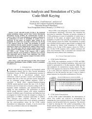
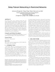
Fig.1 shows an image <strong>of</strong> the analysis model.<br />
Beam divergence angle• •�<br />
Light source<br />
HPCF<br />
core • •�200�m<br />
clad • •�230�m<br />
Plastic container<br />
Light curable resin<br />
2mm 2mm<br />
Fig.1 Analysis model<br />
To form SWWs, we will propagate the laser beam with a<br />
divergence angle to HPCF (Hard Polymer Clad Fiber,<br />
Core/Clad: 200/230�m). It is irradiated to a plastic container<br />
(Full length: 2mm), which is filled with light curable resin.<br />
Table1 shows the analysis condition.<br />
Table 1 Analysis condition<br />
Parameter Value<br />
Number <strong>of</strong> rays 10,000<br />
Curing threshold<br />
More than 90% <strong>of</strong><br />
max. irradiation power<br />
Refractive index <strong>of</strong><br />
light curable resin<br />
Before curing 1.54<br />
After curing 1.57<br />
Beam divergence angle : θ 10°, 30°, 50°<br />
978-1-4244-4522-6/09/$25.00 ©2009 IEEE 993<br />
ISCIT 2009<br />
1mm
There are 4 steps in the analysis.<br />
a) Draw an analysis model, and set the analysis parameters<br />
(For example, the refractive index, number <strong>of</strong> rays from<br />
the light source) <strong>of</strong> a waveguide and light curable resin.<br />
b) Analyze the model using the ray tracing method, and<br />
find the power distribution in the resin.<br />
c) Find the resinous curing part with the threshold wherein<br />
resin cured from maximum irradiation power and create<br />
a curing SWW model with 3D CAD.<br />
d) Place the curing model into the analysis model<br />
After all these steps, repeat steps b) to d) 10 times.<br />
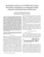
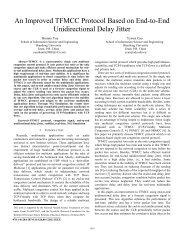
Fig.2 shows the size increase <strong>of</strong> the SWW at each step <strong>of</strong><br />
the analysis. A comparison <strong>of</strong> each step confirms that the<br />
SWW shape and size increasing speed are changed by<br />
changing the beam divergence angle <strong>of</strong> the light source. Both<br />
the maximum width and the shape on the fiber side <strong>of</strong> the<br />
SWW increase as the beam divergence angle increases.<br />
However, the smaller this angle, the faster the SWW travels<br />
as far as the 2mm plastic cell. Note that the SWW increases<br />
less in width at smaller angles. This is because the mode <strong>of</strong><br />
irradiation beam is changed by changing the beam divergence<br />
angle <strong>of</strong> the light source. We infer that it may be possible to<br />
change the shape <strong>of</strong> SWW by controlling these parameters.<br />
Step<br />
2nd<br />
4th<br />
6th<br />
8th<br />
10th<br />
Distance from fiber axis[mm]<br />
10<br />
Beam divergence angle• •� [deg.]<br />
30 50<br />
Distance from fiber side [mm]<br />
Fig.2 SWW shape dependence on the beam divergence angle<br />
III. EXPERIMENT OF SWW FABRICATION<br />
Three differing shapes <strong>of</strong> SWW can be created using<br />
different methods. These are the straight shape, the taper<br />
shape and the reverse taper shape. However, the taper shape is<br />
the most advantageous shape for earning high tolerance width,<br />
when making the connection to the VCSEL (Vertical Cavity<br />
Surface Emitting Laser) side from the waveguide side[2].<br />
This time, we did an experiment using parameters such as<br />
994<br />
beam divergence angle and SWW fabrication time to examine<br />
the feasibility <strong>of</strong> SWW shape control.<br />
The most influential parameter in forming SWW shapes is<br />
the FFP (Far Field Pattern)[3]. We prepared the mode<br />
scrambler with HPCF for driving all modes <strong>of</strong> optical fiber,<br />
and stabilizing the FFP <strong>of</strong> irradiation beam. We used the<br />
FWHM (Full Width Half Maximum) <strong>of</strong> the mode scrambler’s<br />
FFP as the irradiation beam divergence angle. This is a<br />
parameter <strong>of</strong> the SWW fabrication experiment.<br />
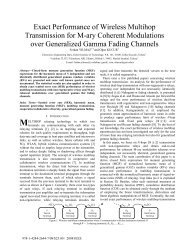
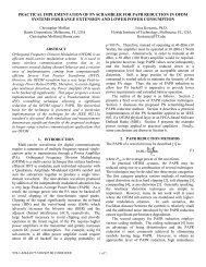
Fig.3 shows the experimental setup. The first step is to<br />
adjust the laser beam from the light source (�=456nm), using<br />
an ND filter and a beam expander. In the second step, we<br />
gather beams <strong>of</strong> light with an object lens, before propagating<br />
to a mode scrambler. Finally, we propagate the beam to a<br />
plastic cell (small container), which is filled with UV curable<br />
resin. After completion, we observe the state <strong>of</strong> the SWWs<br />
formed.<br />
Plastic cell<br />
(15mm)<br />
Fig.3 Experiment setup<br />
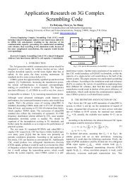
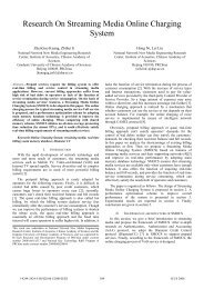
We fabricated SWWs with different divergence angles 7�,<br />
28� and 36�(Measured at part ‘A’ on Fig.3) using three kinds<br />
<strong>of</strong> mode scramblers. Fig.4 shows SWW fabrication results<br />
with irradiation at time ‘6s.’ From these results, we confirm<br />
that it is possible to fabricate the SWW with a straight shape<br />
by decreasing the divergence angle. Likewise, it is possible to<br />
fabricate SWW with a clear tapered shape by increasing the<br />
divergence angle.<br />
Divergence angle [deg.]<br />
36<br />
28<br />
7<br />
Object lens<br />
Mode-scrambler<br />
Beam expander<br />
ND filter<br />
A<br />
0 5 10 15<br />
Distance from the SWW growing end[mm]<br />
Fig.4 SWWs fabricated with divergence angle <strong>of</strong><br />
7�, 28� and 36�. (Fabrication time: 6s)<br />
Laser source<br />
(456nm)<br />
SWW<br />
Fig.5 shows the dimension measurement results <strong>of</strong> SWW<br />
fabricated with a divergence angle <strong>of</strong> 36�. We control the<br />
irradiation power in order to adjust the time that it takes for<br />
the SWW to increase to 15mm (which is the cell’s length).<br />
From this result, we confirmed that it is possible to control the<br />
SWW taper angle not only by changing the divergence angle,
ut also by changing the irradiation time. This is the case,<br />
even when the fabrication times are increased by decreasing<br />
the irradiation power. We notice that as the divergence angle<br />
decreases, it becomes more difficult to change the SWW<br />
shape, because it tends toward a straight shape at smaller<br />
angles. However, we confirm that it is easier to control the<br />
SWW shapes by varying the power at larger divergence<br />
angles.<br />
Fabrication time <strong>of</strong> SWW [sec.]<br />
Diameter <strong>of</strong> SWW [mm]<br />
6<br />
7<br />
8<br />
9<br />
10<br />
1.4<br />
1.2<br />
1.0<br />
0.8<br />
0.6<br />
0.4<br />
0.2<br />
0.0<br />
1mm<br />
0 5 7 10 15<br />
Distance from the SWW growing end [mm]<br />
(a) Pictures <strong>of</strong> fabricated SWW<br />
Fabrication time : 6s<br />
0 2 4 6 8<br />
Distance from the SWW growing end[mm]<br />
(b) Evaluation <strong>of</strong> SWW shape<br />
7s<br />
8s<br />
9s<br />
10s<br />
Fig.5 Evaluation <strong>of</strong> SWW shape (Divergence angle 36°)<br />
IV. SUMMARY<br />
We analyzed the SWW shape control by changing the<br />
beam divergence angle <strong>of</strong> the light source with the ray tracing<br />
method. From these results, we confirm the relationship<br />
between the divergence angle <strong>of</strong> the irradiation beam and the<br />
shape <strong>of</strong> the SWW. In the case <strong>of</strong> wider divergence angles,<br />
the SWW increases in width. In lesser divergence angles, the<br />
SWW increases in speed.<br />
We examined an actual SWW fabrication by changing<br />
parameters such as the irradiation beam divergence angle and<br />
the fabrication time generated by changing irradiation power.<br />
The results show a trend wherein larger divergence angles<br />
fabricate tapered-shape SWWs. Also, we confirm that we can<br />
control the taper angle <strong>of</strong> the SWW shape by changing the<br />
irradiation power. These results were very similar to the<br />
results <strong>of</strong> the previous simulation.<br />
995<br />
These results confirm the possibility <strong>of</strong> controlling SWW<br />
shapes. Thus it is more feasible to practically use SWW in<br />
optical interconnection. More studies are needed to<br />
understand the relationships <strong>of</strong> these parameters and how they<br />
effect the fabrication <strong>of</strong> SWW shapes. In the future, we plan<br />
to pursue these studies to uncover a theory <strong>of</strong> these<br />
parameters and their relationship to forming SWW.<br />
REFERENCES<br />
[1] H. Park, M. Joe and T. Lee , “Technical Guide <strong>of</strong> Optical<br />
PCB(1)”, KPCA Handbook, 2007.<br />
[2] Y. Mimura, T. Tokuhara, T. Shioda and O. Mikami, “Optical<br />
Coupling using Tapered <strong>Self</strong>-<strong>Written</strong> <strong>Waveguide</strong> by Laser<br />
Beam through 45-degree Mirror”, Proceedings <strong>of</strong> the School <strong>of</strong><br />
Information Science and Technology, Tokai University,<br />
Vol.6(2), pp.33-36, 2006.<br />
[3] M. Kagami, T. Yamashita and A. Kawasaki, “Three-<br />
Dimensional Optical <strong>Waveguide</strong> Circuits Using a Light-Induced<br />
<strong>Self</strong>-<strong>Written</strong> Technology”, R&D Review <strong>of</strong> Toyota CRDL,<br />
Vol.37, No.1, pp.44-50, 2001