

Simpson Anchors - Anchoring and Fastening Systems - BuildSite.com
Simpson Anchors - Anchoring and Fastening Systems - BuildSite.com
Simpson Anchors - Anchoring and Fastening Systems - BuildSite.com

Create successful ePaper yourself
Turn your PDF publications into a flip-book with our unique Google optimized e-Paper software.
C-SAS-2009 © 2009 SIMPSON STRONG-TIE COMPANY INC.<br />
SET Technical Information<br />
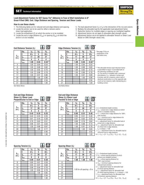
Load-Adjustment Factors for SET Epoxy-Tie ® Adhesive in Face of Wall Installation in 8"<br />
Grout-Filled CMU: End / Edge Distance <strong>and</strong> Spacing, Tension <strong>and</strong> Shear Loads<br />
How to use these charts:<br />
1. The following tables are for reduced end <strong>and</strong> edge distance <strong>and</strong> spacing.<br />
2. Locate the anchor size to be used for either a tension <strong>and</strong>/or<br />
shear load application.<br />
3. Locate the embedment (E) at which the anchor is to be installed.<br />
4. Locate the end or edge distance (C act ) or spacing (S act ) at which the<br />
anchor is to be installed.<br />
End Distance Tension (fc)<br />
Dia. ¹⁄₂ ⁵⁄₈ ³⁄₄<br />
E 4¹⁄₄ 5 6³⁄₄<br />
Ccr 17 20 27<br />
Cmin 4 4 4<br />
fcmin 1.00 0.84 0.54**<br />
4 1.00 0.84 0.54<br />
8 1.00 0.88 0.62<br />
Cact<br />
(in.)<br />
12 1.00 0.92 0 70<br />
16 1.00 0.96 0 78<br />
17 1.00 0.97 0.80<br />
20 1.00 0.86<br />
24 0 94<br />
27 1.00<br />
See Notes Below<br />
End <strong>and</strong> Edge Distance<br />
Shear (fc) Shear Load<br />
Perpendicular to End or Edge<br />
Dia. ¹⁄₂ ⁵⁄₈ ³⁄₄<br />
E 4¹⁄₄ 5 6³⁄₄<br />
Ccr 17 20 27<br />
Cmin 4 4 4<br />
fcmin 0.43 0.25 0.25<br />
4 0.43 0.25 0 25<br />
8 0.61 0.44 0.38<br />
Cact<br />
(in.)<br />
12 0.78 0.63 0.51<br />
16 0.96 0.81 0.64<br />
17 1.00 0.86 0.67<br />
20 1.00 0 77<br />
24 0 90<br />
27 1.00<br />
Spacing Tension (fs)<br />
Dia. ¹⁄₂ ⁵⁄₈ ³⁄₄<br />
E 4¹⁄₄ 5 6³⁄₄<br />
Scr 17 20 27<br />
Smin 8 8 8<br />
fsmin 0.89 0.81 0.59<br />
8 0.89 0.81 0.59<br />
Sact<br />
(in.)<br />
12 0.94 0.87 0.68<br />
16 0.99 0.94 0 76<br />
17 1.00 0.95 0 78<br />
20 1.00 0.85<br />
24 0 94<br />
27 1.00<br />
*<br />
Edge Distance Tension (fc)<br />
Cact<br />
(in.)<br />
Dia. ¹⁄₂ ⁵⁄₈ ³⁄₄ *See page 10 for an<br />
E 4¹⁄₄ 5 6³⁄₄<br />
Ccr 17 20 27<br />
Cmin 4 4 4<br />
fcmin 1.00 0.84 0.54**<br />
4 1.00 0.84 0.54<br />
8 1.00 0.88 0.62<br />
12 1.00 0.92 0 70<br />
16 1.00 0.96 0 78<br />
17 1.00 0.97 0.80<br />
20 1.00 0.86<br />
24 0 94<br />
27 1.00<br />
See Notes Below<br />
*<br />
End <strong>and</strong> Edge Distance<br />
Shear (fc) Shear Load<br />
Parallel to End or Edge<br />
*<br />
Cact<br />
(in.)<br />
Dia. ¹⁄₂ ⁵⁄₈ ³⁄₄<br />
E 4¹⁄₄ 5 6³⁄₄<br />
Ccr 17 20 27<br />
Cmin 4 4 4<br />
fcmin 0.95 0.51 0.45<br />
4 0.95 0.51 0.45<br />
8 0.97 0.63 0.55<br />
12 0.98 0.76 0.64<br />
16 1.00 0.88 0 74<br />
17 1.00 0.91 0 76<br />
20 1.00 0.83<br />
24 0 93<br />
27 1.00<br />
* *<br />
Spacing Shear (fs)<br />
Sact<br />
(in.)<br />
8<br />
12<br />
16<br />
17<br />
20<br />
24<br />
27<br />
5. The load-adjustment factor (f c or f s ) is the intersection of the row <strong>and</strong> column.<br />
6. Multiply the allowable load by the applicable load-adjustment factor.<br />
7. Reduction factors for multiple edges or spacing are multiplied together.<br />
8. Adjustment factors do not apply to allowable steel strength values.<br />
9. Adjustment factors are to be applied to allowable Tension or Shear Load<br />
Based on CMU Strength values only.<br />
Dia. ¹⁄₂ ⁵⁄₈ ³⁄₄<br />
E 4¹⁄₄ 5 6³⁄₄<br />
Scr 17 20 27<br />
Smin 8 8 8<br />
fsmin 1.00 1.00 1.00<br />
1.00 for all spacing ≥ 8 in.<br />
*<br />
explanation of the<br />
load table icons<br />
**The allowable tension load reduction factor<br />
is permitted to equal 1.0 provided both of<br />
the following conditions are met:<br />
(a) The anchor is installed with a minimum<br />
end distance, Cmin, between 4 inches <strong>and</strong><br />
8 inches; <strong>and</strong> (b) a masonry return wall of<br />
identical construction is on the opposite side<br />
(such as two masonry walls intersecting at a<br />
building corner).<br />
1. E = Embedment depth (inches).<br />
2. Cact = actual end or edge distance at which<br />
anchor is installed (inches).<br />
3. Ccr = critical end or edge distance for 100%<br />
load (inches).<br />
4. Cmin = minimum end or edge distance for<br />
reduced load (inches).<br />
5. fc = adjustment factor for allowable load at<br />
actual end or edge distance.<br />
6. fccr = adjustment factor for allowable load<br />
at critical end or edge distance.<br />
fccr is always = 1.00.<br />
7. fcmin = adjustment factor for allowable load at<br />
minimum end or edge distance.<br />
8. fc = fcmin + [(1 - fcmin) (Cact - Cmin) / (Ccr - Cmin)].<br />
1. E = Embedment depth (inches).<br />
2. Sact = actual spacing distance at which<br />
anchors are installed (inches).<br />
3. Scr = critical spacing distance for<br />
100% load (inches).<br />
4. Smin = minimum spacing distance for<br />
reduced load (inches).<br />
5. fs = adjustment factor for allowable load<br />
at actual spacing distance.<br />
6. fscr = adjustment factor for allowable load<br />
at critical spacing distance. fscr is always = 1.00.<br />
7. fsmin = adjustment factor for allowable load<br />
at minimum spacing distance.<br />
8. fs = fsmin + [(1 - fsmin) (Sact - Smin) / (Scr - Smin)].<br />
Epoxy Adhesives<br />
53


