

Simpson Anchors - Anchoring and Fastening Systems - BuildSite.com
Simpson Anchors - Anchoring and Fastening Systems - BuildSite.com
Simpson Anchors - Anchoring and Fastening Systems - BuildSite.com

You also want an ePaper? Increase the reach of your titles
YUMPU automatically turns print PDFs into web optimized ePapers that Google loves.
Gas-Actuated <strong>Fastening</strong> System<br />
182<br />
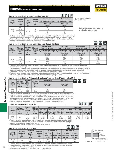
GCN150 Gas-Actuated Concrete Nailer<br />
Tension <strong>and</strong> Shear Loads in S<strong>and</strong>-Lightweight Concrete<br />
Shank<br />
Diameter<br />
in.<br />
0.106<br />
(2.7)<br />
Tension <strong>and</strong> Shear Loads in S<strong>and</strong>-Lightweight Concrete over Metal deck<br />
Shank<br />
Diameter<br />
in.<br />
0.106<br />
(2.7)<br />
Minimum<br />
Penetration<br />
in.<br />
(mm)<br />
Minimum<br />
Edge<br />
Distance<br />
in.<br />
(mm)<br />
⁵⁄₈<br />
(15.9) 1<br />
¾ (25.4)<br />
(19.1)<br />
Minimum<br />
Spacing<br />
in.<br />
(mm)<br />
4<br />
(102)<br />
Tension Loads –<br />
Thru 1.5" “B” Deck<br />
Shear Loads –<br />
Thru 1.5" “B” Deck<br />
Tension Loads –<br />
Thru 3" “W” Deck<br />
Shear Loads –<br />
Thru 3" “W” Deck<br />
f' c ≥ 3000 psi (20.7 Mpa) f' c ≥ 3000 psi (20.7 Mpa) f' c ≥ 3000 psi (20.7 Mpa) f' c ≥ 3000 psi (20.7 Mpa)<br />
Allow. Load<br />
lbs. (kN)<br />
65<br />
(0.29)<br />
130<br />
(0.58)<br />
Allow. Load<br />
lbs. (kN)<br />
195<br />
(0.87)<br />
270<br />
(1.20)<br />
Tension <strong>and</strong> Shear Loads in 8" Lightweight, Medium-Weight <strong>and</strong> Normal-Weight Hollow CMU<br />
Shank<br />
Diameter<br />
in.<br />
0.106<br />
(2.7)<br />
Minimum<br />
Penetration<br />
in.<br />
(mm)<br />
Minimum<br />
Penetration<br />
in.<br />
(mm)<br />
⁵⁄₈<br />
(15.9)<br />
Minimum<br />
Edge<br />
Distance<br />
in.<br />
(mm)<br />
⁵⁄₈<br />
(15.9) 3<br />
(76.2)<br />
¾<br />
(19.1)<br />
Minimum<br />
Edge<br />
Distance<br />
in.<br />
(mm)<br />
3<br />
(76.2)<br />
Minimum<br />
Spacing<br />
in.<br />
(mm)<br />
4<br />
(102)<br />
Minimum<br />
Spacing<br />
in.<br />
(mm)<br />
8<br />
(203)<br />
Tension <strong>and</strong> Shear Loads in A36 Steel<br />
Tension Loads Shear Loads<br />
f' c ≥ 3000 psi (20.7 Mpa) f' c ≥ 3000 psi (20.7 Mpa)<br />
Allow. Load<br />
lbs. (kN)<br />
75<br />
(0.33)<br />
105<br />
(0.47)<br />
Tension Loads Shear Loads<br />
Allow. Load<br />
lbs. (kN)<br />
35<br />
(0.16)<br />
Allow. Load<br />
lbs. (kN)<br />
35<br />
(0.16)<br />
140<br />
(0.62)<br />
1. The fasteners must not be driven until the lightweight concrete has reached the designated minimum <strong>com</strong>pressive strength.<br />
2. Minimum lightweight concrete thickness must be three times the fastener embedment into the lightweight concrete.<br />
3. The allowable shear <strong>and</strong> tension values are only for the fasteners in the lightweight concrete. Members connected to the<br />
lightweight concrete must be investigated in accordance with accepted design criteria.<br />
Allow. Load<br />
lbs. (kN)<br />
50<br />
(0.22)<br />
*<br />
*See page 10 for an explanation<br />
of the load table icons<br />
Allow. Load<br />
lbs. (kN)<br />
60<br />
(0.27)<br />
60<br />
(0.27)<br />
1. The fasteners must not be driven through the steel deck <strong>and</strong> into the lightweight concrete until the lightweight concrete has reached the designated<br />
minimum <strong>com</strong>pressive strength.<br />
2. The allowable shear <strong>and</strong> tension values are only for the fasteners driven through the steel deck <strong>and</strong> into the lightweight concrete. Members connected by<br />
the fastener, driven through the steel deck <strong>and</strong> into the lightweight concrete, must be investigated in accordance with accepted design criteria.<br />
4. The steel deck must have a minimum thickness of 20 gage <strong>and</strong> a minimum yield strength of 38 ksi.<br />
5. The fasteners must be installed through the steel deck <strong>and</strong> into the concrete at the lower flute. The fastener must be a minimum of 1 inch from the edge<br />
of the lower flute <strong>and</strong> 3 inches from the end of the deck. The minimum fastener spacing is 4 inches.<br />
1. The tabulated allowable load values are for the fasteners only. Members connected to the CMU receiving elements shall be<br />
designed in accordance with the applicable code <strong>and</strong> accepted design criteria.<br />
2. The tabulated allowable load values are for fasteners installed in hollow CMUs conforming to ASTM C 90. The minimum<br />
allowable nominal size of the CMU must be 8 inches high by 8 inches wide by 16 inches long, with a minimum,1¹⁄₄"-thick<br />
face shell thickness, Grade N, Type II, lightweight, medium-weight <strong>and</strong> normal weight concrete masonry units.<br />
3. The tabulated allowable load values are for fasteners installed in the center of a hollow CMU face shell.<br />
Note: All installations are limited to<br />
dry, interior environments.<br />
Minimum<br />
Minimum<br />
Minimum<br />
Tension Loads Shear Loads<br />
Shank<br />
Edge<br />
Penetration<br />
Spacing<br />
Diameter<br />
Distance<br />
¹⁄₈" Thick ³⁄₁₆" Thick ¹⁄₄" Thick ¹⁄₈" Thick ³⁄₁₆" Thick ¹⁄₄" Thick<br />
in.<br />
in.<br />
in.<br />
in.<br />
Allow. Load Allow. Load Allow. Load Allow. Load Allow. Load Allow. Load<br />
(mm)<br />
(mm)<br />
(mm)<br />
lbs. (kN) lbs. (kN) lbs. (kN) lbs. (kN) lbs. (kN) lbs. (kN)<br />
0.106<br />
Thru ½ 1 125 210 220 285 225 205<br />
(2.7)<br />
(12.7) (25.4) (0.56) (0.93) (0.98) (1.27) (1.00) (0.91)<br />
1. The entire pointed portion of the fastener must penetrate through the steel to obtain the tabulated values. See Detail A.<br />
2. The allowable tension <strong>and</strong> shear values are for the fastener only. Members connected to the steel must be investigated<br />
separately in accordance with accepted design criteria.<br />
3. Steel must conform to ASTM A36 specifications, with Fy = 36 ksi, minimum.<br />
*<br />
Tension <strong>and</strong> Shear Loads in A572 Steel<br />
Minimum<br />
Minimum<br />
Minimum<br />
Tension Loads Shear Loads<br />
Shank<br />
Edge<br />
Penetration<br />
Spacing ³⁄₁₆" Thick ¹⁄₄" Thick ³⁄₁₆" Thick ¹⁄₄" Thick<br />
Diameter<br />
Distance<br />
in.<br />
in.<br />
in.<br />
in.<br />
Allow. Load Allow. Load Allow. Load Allow. Load<br />
(mm)<br />
(mm)<br />
(mm)<br />
lbs. (kN) lbs. (kN) lbs. (kN) lbs. (kN)<br />
0.106<br />
Thru ½ 1 225 185 250 145<br />
(2.7)<br />
(12.7) (25.4) (1.00) (0.82) (1.11) (0.64)<br />
Detail A<br />
1. The entire pointed portion of the fastener must penetrate through the steel to obtain the tabulated values. See Detail A.<br />
2. The allowable tension <strong>and</strong> shear values are for the fastener only. Members connected to the steel must be investigated<br />
separately in accordance with accepted design criteria.<br />
3. Steel must conform to ASTM A572 specifications, with Fy = 50 ksi, minimum.<br />
*<br />
*<br />
Allow. Load<br />
lbs. (kN)<br />
180<br />
(0.80)<br />
180<br />
(0.80)<br />
GAS ACTUATED<br />
FASTENER<br />
STEEL<br />
THICKNESS<br />
ENTIRE POINTED PORTION<br />
OF THE FASTENER MUST<br />
PENETRATE THROUGH<br />
THE STEEL<br />
*<br />
C-SAS-2009 © 2009 SIMPSON STRONG-TIE COMPANY INC.


