

Simpson Anchors - Anchoring and Fastening Systems - BuildSite.com
Simpson Anchors - Anchoring and Fastening Systems - BuildSite.com
Simpson Anchors - Anchoring and Fastening Systems - BuildSite.com

You also want an ePaper? Increase the reach of your titles
YUMPU automatically turns print PDFs into web optimized ePapers that Google loves.
Mechanical <strong>Anchors</strong><br />
152<br />
SLEEVE-ALL ®<br />
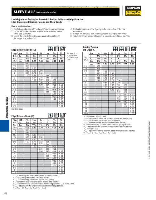
Load-Adjustment Factors for Sleeve-All ® <strong>Anchors</strong> in Normal-Weight Concrete:<br />
Edge Distance <strong>and</strong> Spacing, Tension <strong>and</strong> Shear Loads<br />
How to use these charts:<br />
1. The following tables are for reduced edge distance <strong>and</strong> spacing.<br />
2. Locate the anchor size to be used for either a tension <strong>and</strong>/or<br />
shear load application.<br />
3. Locate the edge distance (Cact ) or spacing (Sact ) at which<br />
the anchor is to be installed.<br />
Edge Distance Tension (fc)<br />
Edge<br />
Dist.<br />
Cact<br />
(in.)<br />
Size ¹⁄₄ ⁵⁄₁₆ ³⁄₈ ¹⁄₂ ⁵⁄₈ ³⁄₄ *See page 10 for<br />
Ccr 2¹⁄₂ 3¹⁄₈ 3³⁄₄ 5 6¹⁄₄ 7¹⁄₂<br />
Cmin 1¹⁄₄ 1⁹⁄₁₆ 1⁷⁄₈ 2¹⁄₂ 3¹⁄₈ 3³⁄₄<br />
fcmin 0.60 0.60 0.60 0.60 0.60 0.60<br />
1¹⁄₄ 0.60<br />
1¹⁄₂ 0.68<br />
1⁹⁄₁₆ 0.70 0.60<br />
1⁷⁄₈ 0.80 0.68 0.60<br />
2 0.84 0.71 0.63<br />
2¹⁄₂ 1.00 0.84 0.73 0.60<br />
3 0.97 0.84 0.68<br />
3¹⁄₈ 1.00 0.87 0.70 0.60<br />
3¹⁄₂ 0.95 0.76 0.65<br />
3³⁄₄ 1.00 0.80 0.68 0.60<br />
4 0.84 0.71 0.63<br />
4¹⁄₂ 0.92 0.78 0.68<br />
5 1.00 0.84 0.73<br />
5¹⁄₂ 0.90 0.79<br />
6 0.97 0.84<br />
6¹⁄₄ 1.00 0.87<br />
6¹⁄₂ 0.89<br />
7 0.95<br />
7¹⁄₂ 1.00<br />
See Notes Below<br />
Edge Distance Shear (fc)<br />
Edge<br />
Dist.<br />
Cact<br />
(in.)<br />
Technical Information<br />
Size ¹⁄₄ ⁵⁄₁₆ ³⁄₈ ¹⁄₂ ⁵⁄₈ ³⁄₄<br />
Ccr 2¹⁄₂ 3¹⁄₈ 3³⁄₄ 5 6¹⁄₄ 7¹⁄₂<br />
Cmin 1¹⁄₄ 1⁹⁄₁₆ 1⁷⁄₈ 2¹⁄₂ 3¹⁄₈ 3³⁄₄<br />
fcmin 0.30 0.30 0.30 0.30 0.30 0.30<br />
1¹⁄₄ 0.30<br />
1¹⁄₂ 0.44<br />
1⁹⁄₁₆ 0.48 0.30<br />
1⁷⁄₈ 0.65 0.44 0.30<br />
2 0.72 0.50 0.35<br />
2¹⁄₂ 1.00 0.72 0.53 0.30<br />
3 0.94 0.72 0.44<br />
3¹⁄₈ 1.00 0.77 0.48 0.30<br />
3¹⁄₂ 0.91 0.58 0.38<br />
3³⁄₄ 1.00 0.65 0.44 0.30<br />
4 0.72 0.50 0.35<br />
4¹⁄₂ 0.86 0.61 0.44<br />
5 1.00 0.72 0.53<br />
5¹⁄₂ 0.83 0.63<br />
6 0.94 0.72<br />
6¹⁄₄ 1.00 0.77<br />
6¹⁄₂ 0.81<br />
7 0.91<br />
7¹⁄₂ 1.00<br />
*<br />
*<br />
4. The load adjustment factor (f c or f s ) is the intersection of the row<br />
<strong>and</strong> column.<br />
5. Multiply the allowable load by the applicable load adjustment factor.<br />
6. Reduction factors for multiple edges or spacing are multiplied together.<br />
an explanation<br />
of the load table<br />
icons<br />
1. Cact = actual edge distance at which anchor is installed (inches).<br />
2. Ccr = critical edge distance for 100% load (inches).<br />
3. Cmin = minimum edge distance for reduced load (inches).<br />
4. fc = adjustment factor for allowable load at actual edge distance.<br />
5. fccr = adjustment factor for allowable load at critical edge distance. fccr is always = 1.00.<br />
6. fcmin = adjustment factor for allowable load at minimum edge distance.<br />
7. fc = fcmin + [(1 - fcmin) (Cact - Cmin) / (Ccr - Cmin)].<br />
Spacing Tension<br />
<strong>and</strong> Shear (fs)<br />
Sact<br />
(in.)<br />
Size ¹⁄₄ ⁵⁄₁₆ ³⁄₈ ¹⁄₂ ⁵⁄₈ ³⁄₄<br />
E 1¹⁄₈ 1⁷⁄₁₆ 1¹⁄₂ 2¹⁄₄ 2³⁄₄ 3³⁄₈<br />
Scr 4¹⁄₂ 5³⁄₄ 6 9 11 13¹⁄₂<br />
Smin 2¹⁄₄ 2⁷⁄₈ 3 4¹⁄₂ 5¹⁄₂ 6³⁄₄<br />
fsmin 0.50 0.50 0.50 0.50 0.50 0.50<br />
2¹⁄₄ 0.50<br />
2¹⁄₂ 0.56<br />
2⁷⁄₈ 0.64 0.50<br />
3 0.67 0.52 0.50<br />
3¹⁄₂ 0.78 0.61 0.58<br />
4 0.89 0.70 0.67<br />
4¹⁄₂ 1.00 0.78 0.75 0.50<br />
5 0.87 0.83 0.56<br />
5¹⁄₂ 0.96 0.92 0.61 0.50<br />
5³⁄₄ 1.00 0.96 0.64 0.52<br />
6 1.00 0.67 0.55<br />
6¹⁄₂ 0.72 0.59<br />
6³⁄₄ 0.75 0.61 0.50<br />
7 0.78 0.64 0.52<br />
8 0.89 0.73 0.59<br />
9 1.00 0.82 0.67<br />
10 0.91 0.74<br />
11 1.00 0.81<br />
12 0.89<br />
13 0.96<br />
13¹⁄₂ 1.00<br />
1. E = Embedment depth (inches).<br />
2. Sact = actual spacing distance at which anchors are installed (inches).<br />
3. Scr = critical spacing distance for 100% load (inches).<br />
4. Smin = minimum spacing distance for reduced load (inches).<br />
5. fs = adjustment factor for allowable load at actual spacing distance.<br />
6. fscr = adjustment factor for allowable load at critical spacing distance.<br />
fscr is always = 1.00.<br />
7. fsmin = adjustment factor for allowable load at minimum spacing distance.<br />
8. fs = fsmin + [(1 - fsmin) (Sact - Smin) / (Scr - Smin)].<br />
*<br />
C-SAS-2009 © 2009 SIMPSON STRONG-TIE COMPANY INC.


