

Simpson Anchors - Anchoring and Fastening Systems - BuildSite.com
Simpson Anchors - Anchoring and Fastening Systems - BuildSite.com
Simpson Anchors - Anchoring and Fastening Systems - BuildSite.com

Create successful ePaper yourself
Turn your PDF publications into a flip-book with our unique Google optimized e-Paper software.
Mechanical <strong>Anchors</strong><br />
148<br />
WEDGE-ALL ®<br />
Edge Distance Tension (fc)<br />
Edge<br />
Dist.<br />
Cact<br />
(in.)<br />
Size ¹⁄₄ ¹⁄₂ ⁵⁄₈ ³⁄₄<br />
Ccr 3³⁄₈ 6³⁄₄ 8³⁄₈ 10<br />
Cmin 1³⁄₈ 2³⁄₄ 3³⁄₈ 4<br />
fcmin 0.70 0.70 0.70 0.70<br />
1³⁄₈ 0.70<br />
1¹⁄₂ 0.72<br />
2 0.79<br />
2¹⁄₂ 0.87<br />
2³⁄₄ 0.91 0.70<br />
3 0.94 0.72<br />
3³⁄₈ 1.00 0.75 0.70<br />
3¹⁄₂ 0.76 0.71<br />
4 0.79 0.74 0.70<br />
4¹⁄₂ 0.83 0.77 0.73<br />
5 0.87 0.80 0.75<br />
5¹⁄₂ 0.91 0.83 0.78<br />
6 0.94 0.86 0.80<br />
6¹⁄₂ 0.98 0.89 0.83<br />
6³⁄₄ 1.00 0.90 0.84<br />
7 0.92 0.85<br />
7¹⁄₂ 0.95 0.88<br />
8 0.98 0.90<br />
8³⁄₈ 1.00 0.92<br />
8¹⁄₂ 0.93<br />
9 0.95<br />
9¹⁄₂ 0.98<br />
10 1.00<br />
See Notes Below<br />
Edge Distance Tension (fc)<br />
Edge<br />
Dist.<br />
Cact<br />
(in.)<br />
ANCHOR Technical Information<br />
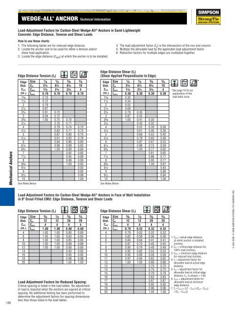
Load-Adjustment Factors for Carbon-Steel Wedge-All ® <strong>Anchors</strong> in S<strong>and</strong>-Lightweight<br />
Concrete: Edge Distance, Tension <strong>and</strong> Shear Loads<br />
How to use these charts:<br />
1. The following tables are for reduced edge distance.<br />
2. Locate the anchor size to be used for either a tension <strong>and</strong>/or<br />
shear load application.<br />
3. Locate the edge distance (Cact ) at which the anchor is to be installed.<br />
Size ³⁄₈ ¹⁄₂ ⁵⁄₈ ³⁄₄<br />
Ccr 12 12 20 20<br />
Cmin 4 4 4 4<br />
fcmin 1.00 1.00 0.80 0.80<br />
4 1.00 1.00 0.80 0.80<br />
6 1.00 1.00 0.83 0.83<br />
8 1.00 1.00 0.85 0.85<br />
10 1.00 1.00 0.88 0.88<br />
12 1.00 1.00 0.90 0.90<br />
14 0.93 0.93<br />
16 0.95 0.95<br />
18 0.98 0.98<br />
20 1.00 1.00<br />
Edge Distance Shear (fc)<br />
(Shear Applied Perpendicular to Edge)<br />
Edge<br />
Dist.<br />
Cact<br />
(in.)<br />
Size ¹⁄₄ ¹⁄₂ ⁵⁄₈ ³⁄₄<br />
Ccr 3³⁄₈ 6³⁄₄ 8³⁄₈ 10<br />
Cmin 1³⁄₈ 2³⁄₄ 3³⁄₈ 4 *See page 10 for an<br />
fcmin 0.30 0.30 0.30 0.30<br />
1³⁄₈ 0.30<br />
1¹⁄₂ 0.34<br />
2 0.52<br />
2¹⁄₂ 0.69<br />
2³⁄₄ 0.78 0.30<br />
3 0.87 0.34<br />
3³⁄₈ 1.00 0.41 0.30<br />
3¹⁄₂ 0.43 0.32<br />
4 0.52 0.39 0.30<br />
4¹⁄₂ 0.61 0.46 0.36<br />
5 0.69 0.53 0.42<br />
5¹⁄₂ 0.78 0.60 0.48<br />
6 0.87 0.67 0.53<br />
6¹⁄₂ 0.96 0.74 0.59<br />
6³⁄₄ 1.00 0.77 0.62<br />
7 0.81 0.65<br />
7¹⁄₂ 0.88 0.71<br />
8 0.95 0.77<br />
8³⁄₈ 1.00 0.81<br />
8¹⁄₂ 0.83<br />
9 0.88<br />
9¹⁄₂ 0.94<br />
10 1.00<br />
See Notes Below<br />
Load-Adjustment Factors for Carbon-Steel Wedge-All ® <strong>Anchors</strong> in Face of Wall Installation<br />
in 8" Grout-Filled CMU: Edge Distance, Tension <strong>and</strong> Shear Loads<br />
Load-Adjustment Factors for Reduced Spacing:<br />
Critical spacing is listed in the load tables. No adjustment<br />
in load is required when the anchors are spaced at critical<br />
spacing. No additional testing has been performed to<br />
determine the adjustment factors for spacing dimensions<br />
less than those listed in the load tables.<br />
*<br />
* *<br />
Edge Distance Shear (fc)<br />
Edge<br />
Dist.<br />
Cact<br />
(in.)<br />
4. The load adjustment factor (f c ) is the intersection of the row <strong>and</strong> column.<br />
5. Multiply the allowable load by the applicable load adjustment factor.<br />
6. Reduction factors for multiple edges are multiplied together.<br />
Size ³⁄₈ ¹⁄₂ ⁵⁄₈ ³⁄₄<br />
Ccr 12 12 20 20<br />
Cmin 4 4 4 4<br />
fcmin 0.79 0.52 0.32 0.32<br />
4 0.79 0.52 0.32 0.32<br />
5 0.82 0.58 0.36 0.36<br />
6 0.84 0.64 0.41 0.41<br />
7 0.87 0.70 0.45 0.45<br />
8 0.90 0.76 0.49 0.49<br />
9 0.92 0.82 0.53 0.53<br />
10 0.95 0.88 0.58 0.58<br />
11 0.97 0.94 0.62 0.62<br />
12 1.00 1.00 0.66 0.66<br />
13 0.70 0.70<br />
14 0.75 0.75<br />
15 0.79 0.79<br />
16 0.83 0.83<br />
17 0.87 0.87<br />
18 0.92 0.92<br />
19 0.96 0.96<br />
20 1.00 1.00<br />
explanation of the<br />
load table icons<br />
*<br />
1. Cact = actual edge distance<br />
at which anchor is installed<br />
(inches).<br />
2. Ccr = critical edge distance for<br />
100% load (inches).<br />
3. Cmin = minimum edge distance<br />
for reduced load (inches).<br />
4. fc = adjustment factor for<br />
allowable load at actual edge<br />
distance.<br />
5. fccr = adjustment factor for<br />
allowable load at critical edge<br />
distance. fccr is always = 1.00.<br />
6. fcmin = adjustment factor for<br />
allowable load at minimum<br />
edge distance.<br />
7. fc = fcmin + [(1 - fcmin) (Cact - Cmin)<br />
/ (Ccr - Cmin)].<br />
C-SAS-2009 © 2009 SIMPSON STRONG-TIE COMPANY INC.


