

Simpson Anchors - Anchoring and Fastening Systems - BuildSite.com
Simpson Anchors - Anchoring and Fastening Systems - BuildSite.com
Simpson Anchors - Anchoring and Fastening Systems - BuildSite.com

You also want an ePaper? Increase the reach of your titles
YUMPU automatically turns print PDFs into web optimized ePapers that Google loves.
C-SAS-2009 © 2009 SIMPSON STRONG-TIE COMPANY INC.<br />
WEDGE-ALL ®<br />
Spacing Shear (fs)<br />
Sact<br />
(in.)<br />
Dia. ¹⁄₄ ³⁄₈ ¹⁄₂ ⁵⁄₈ *See page 10 for<br />
E 1¹⁄₈ 2¹⁄₄ 1³⁄₄ 2⁵⁄₈ 3³⁄₈ 2¹⁄₄ 3³⁄₈ 4¹⁄₂ 2³⁄₄ 4¹⁄₂ 5¹⁄₂<br />
Scr 1⁵⁄₈ 3¹⁄₈ 2³⁄₈ 3⁵⁄₈ 4³⁄₄ 3¹⁄₈ 4³⁄₄ 6¹⁄₄ 3⁷⁄₈ 6¹⁄₄ 7³⁄₄<br />
Smin ⁵⁄₈ 1¹⁄₈ ⁷⁄₈ 1³⁄₈ 1³⁄₄ 1¹⁄₈ 1³⁄₄ 2¹⁄₄ 1³⁄₈ 2¹⁄₄ 2³⁄₄<br />
fsmin 0.79 0.79 0.79 0.79 0.79 0.79 0.79 0.79 0.79 0.79 0.79<br />
³⁄₄ 0.82<br />
1 0.87 0.81<br />
1¹⁄₄ 0.92 0.80 0.84 0.80<br />
1¹⁄₂ 0.97 0.83 0.88 0.80 0.83 0.80<br />
1³⁄₄ 1.00 0.86 0.91 0.83 0.79 0.86 0.79 0.82<br />
2 0.88 0.95 0.85 0.81 0.88 0.81 0.84<br />
2¹⁄₄ 0.91 0.98 0.87 0.83 0.91 0.83 0.79 0.86 0.79<br />
2¹⁄₂ 0.93 1.00 0.90 0.84 0.93 0.84 0.80 0.88 0.80<br />
2³⁄₄ 0.96 0.92 0.86 0.96 0.86 0.82 0.91 0.82 0.79<br />
3 0.99 0.94 0.88 0.99 0.88 0.83 0.93 0.83 0.80<br />
3¹⁄₂ 1.00 0.99 0.91 1.00 0.91 0.86 0.97 0.86 0.82<br />
4 1.00 0.95 0.95 0.88 1.00 0.88 0.84<br />
4¹⁄₂ 0.98 0.98 0.91 0.91 0.86<br />
5 1.00 1.00 0.93 0.93 0.88<br />
6 0.99 0.99 0.93<br />
7 1.00 1.00 0.97<br />
8 1.00<br />
See Notes Below<br />
Spacing Shear (fs)<br />
Sact<br />
(in.)<br />
ANCHOR Technical Information<br />
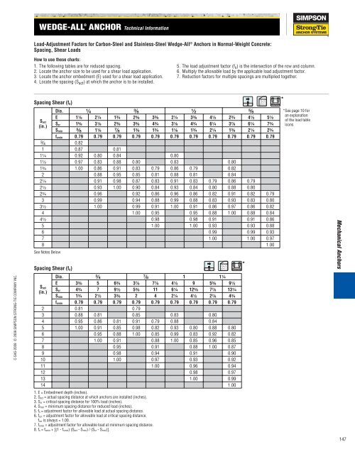
Load-Adjustment Factors for Carbon-Steel <strong>and</strong> Stainless-Steel Wedge-All ® <strong>Anchors</strong> in Normal-Weight Concrete:<br />
Spacing, Shear Loads<br />
How to use these charts:<br />
1. The following tables are for reduced spacing.<br />
2. Locate the anchor size to be used for a shear load application.<br />
3. Locate the anchor embedment (E) used for a shear load application.<br />
4. Locate the spacing (Sact ) at which the anchor is to be installed.<br />
Dia. ³⁄₄ ⁷⁄₈ 1 1¹⁄₄<br />
E 3³⁄₈ 5 6³⁄₄ 3⁷⁄₈ 7⁷⁄₈ 4¹⁄₂ 9 5⁵⁄₈ 9¹⁄₂<br />
Scr 4³⁄₄ 7 9¹⁄₂ 5³⁄₈ 11 6¹⁄₄ 12⁵⁄₈ 7⁷⁄₈ 13¹⁄₄<br />
Smin 1³⁄₄ 2¹⁄₂ 3³⁄₈ 2 4 2¹⁄₄ 4¹⁄₂ 2⁷⁄₈ 4³⁄₄<br />
fsmin 0.79 0.79 0.79 0.79 0.79 0.79 0.79 0.79 0.79<br />
2 0.81 0.79<br />
3 0.88 0.81 0.85 0.83 0.80<br />
4 0.95 0.86 0.81 0.91 0.79 0.88 0.84<br />
5 1.00 0.91 0.85 0.98 0.82 0.93 0.80 0.88 0.80<br />
6 0.95 0.88 1.00 0.85 0.99 0.83 0.92 0.82<br />
7 1.00 0.91 0.88 1.00 0.85 0.96 0.85<br />
8 0.95 0.91 0.88 1.00 0.87<br />
9 0.98 0.94 0.91 0.90<br />
10 1.00 0.97 0.93 0.92<br />
11 1.00 0.96 0.94<br />
12 0.98 0.97<br />
13 1.00 0.99<br />
14 1.00<br />
1. E = Embedment depth (inches).<br />
2. Sact = actual spacing distance at which anchors are installed (inches).<br />
3. Scr = critical spacing distance for 100% load (inches).<br />
4. Smin = minimum spacing distance for reduced load (inches).<br />
5. fs = adjustment factor for allowable load at actual spacing distance.<br />
6. fscr = adjustment factor for allowable load at critical spacing distance.<br />
fscr is always = 1.00.<br />
7. fsmin = adjustment factor for allowable load at minimum spacing distance.<br />
8. fs = fsmin + [(1 - fsmin) (Sact - Smin) / (Scr - Smin)].<br />
5. The load adjustment factor (f s ) is the intersection of the row <strong>and</strong> column.<br />
6. Multiply the allowable load by the applicable load adjustment factor.<br />
7. Reduction factors for multiple spacings are multiplied together.<br />
*<br />
*<br />
an explanation<br />
of the load table<br />
icons<br />
Mechanical <strong>Anchors</strong><br />
147


