

Simpson Anchors - Anchoring and Fastening Systems - BuildSite.com
Simpson Anchors - Anchoring and Fastening Systems - BuildSite.com
Simpson Anchors - Anchoring and Fastening Systems - BuildSite.com

You also want an ePaper? Increase the reach of your titles
YUMPU automatically turns print PDFs into web optimized ePapers that Google loves.
Mechanical <strong>Anchors</strong><br />
128<br />
TITEN HD ®<br />
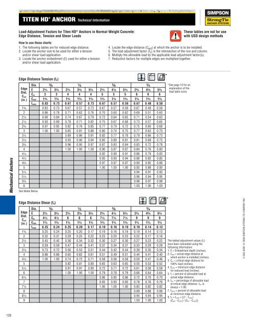
Load-Adjustment Factors for Titen HD ® <strong>Anchors</strong> in Normal-Weight Concrete:<br />
Edge Distance, Tension <strong>and</strong> Shear Loads<br />
How to use these charts:<br />
1. The following tables are for reduced edge distance.<br />
2. Locate the anchor size to be used for either a tension<br />
<strong>and</strong>/or shear load application.<br />
3. Locate the anchor embedment (E) used for either a tension<br />
<strong>and</strong>/or shear load application.<br />
Edge Distance Tension (fc)<br />
Edge<br />
Dist.<br />
Cact<br />
(in.)<br />
4. Locate the edge distance (C act ) at which the anchor is to be installed.<br />
5. The load adjustment factor (f c ) is the intersection of the row <strong>and</strong> column.<br />
6. Multiply the allowable load by the applicable load adjustment factor(s).<br />
7. Reduction factors for multiple edges are multiplied together.<br />
Dia. ³⁄₈ ¹⁄₂ ⁵⁄₈ ³⁄₄ *See page 10 for an<br />
E 2³⁄₄ 3³⁄₄ 2³⁄₄ 3⁵⁄₈ 5³⁄₄ 2³⁄₄ 4¹⁄₈ 5³⁄₄ 2³⁄₄ 4⁵⁄₈ 5³⁄₄<br />
Ccr 3 3 4 4 4 5 5 5 6 6 6<br />
Cmin 1³⁄₄ 1³⁄₄ 1³⁄₄ 1³⁄₄ 1³⁄₄ 1³⁄₄ 1³⁄₄ 1³⁄₄ 1³⁄₄ 1³⁄₄ 1³⁄₄<br />
fcmin 0.83 0.73 0.67 0.57 0.73 0.67 0.57 0.59 0.67 0.48 0.58<br />
1³⁄₄ 0.83 0.73 0.67 0.57 0.73 0.67 0.57 0.59 0.67 0.48 0.58<br />
2 0.86 0.78 0.71 0.62 0.76 0.70 0.60 0.62 0.69 0.51 0.60<br />
2¹⁄₄ 0.90 0.84 0.74 0.67 0.79 0.72 0.64 0.65 0.71 0.54 0.63<br />
2¹⁄₂ 0.93 0.89 0.78 0.71 0.82 0.75 0.67 0.68 0.73 0.57 0.65<br />
2³⁄₄ 0.97 0.95 0.82 0.76 0.85 0.77 0.70 0.72 0.75 0.60 0.68<br />
3 1.00 1.00 0.85 0.81 0.88 0.80 0.74 0.75 0.77 0.63 0.70<br />
3¹⁄₄ 0.89 0.86 0.91 0.82 0.77 0.78 0.79 0.66 0.73<br />
3¹⁄₂ 0.93 0.90 0.94 0.85 0.80 0.81 0.81 0.69 0.75<br />
3³⁄₄ 0.96 0.95 0.97 0.87 0.83 0.84 0.83 0.72 0.78<br />
4 1.00 1.00 1.00 0.90 0.87 0.87 0.84 0.76 0.80<br />
4¹⁄₄ 0.92 0.90 0.91 0.86 0.79 0.83<br />
4¹⁄₂ 0.95 0.93 0.94 0.88 0.82 0.85<br />
4³⁄₄ 0.97 0.97 0.97 0.90 0.85 0.88<br />
5 1.00 1.00 1.00 0.92 0.88 0.90<br />
5¹⁄₄ 0.94 0.91 0.93<br />
5¹⁄₂ 0.96 0.94 0.95<br />
5³⁄₄ 0.98 0.97 0.98<br />
6 1.00 1.00 1.00<br />
See Notes Below<br />
Edge Distance Shear (fc)<br />
Edge<br />
Dist.<br />
Cact<br />
(in.)<br />
ANCHOR Technical Information<br />
Dia. ³⁄₈ ¹⁄₂ ⁵⁄₈ ³⁄₄<br />
E 2³⁄₄ 3³⁄₄ 2³⁄₄ 3⁵⁄₈ 5³⁄₄ 2³⁄₄ 4¹⁄₈ 5³⁄₄ 2³⁄₄ 4⁵⁄₈ 5³⁄₄<br />
Ccr 4¹⁄₂ 4¹⁄₂ 6 6 6 7¹⁄₂ 7¹⁄₂ 7¹⁄₂ 9 9 9<br />
Cmin 1³⁄₄ 1³⁄₄ 1³⁄₄ 1³⁄₄ 1³⁄₄ 1³⁄₄ 1³⁄₄ 1³⁄₄ 1³⁄₄ 1³⁄₄ 1³⁄₄<br />
fcmin 0.25 0.24 0.25 0.20 0.17 0.19 0.16 0.19 0.19 0.14 0.13<br />
1³⁄₄ 0.25 0.24 0.25 0.20 0.17 0.19 0.16 0.19 0.19 0.14 0.13<br />
2 0.32 0.31 0.29 0.25 0.22 0.23 0.20 0.23 0.22 0.17 0.16<br />
2¹⁄₂ 0.45 0.45 0.38 0.34 0.32 0.30 0.27 0.30 0.27 0.23 0.22<br />
3 0.59 0.59 0.47 0.44 0.41 0.37 0.34 0.37 0.33 0.29 0.28<br />
3¹⁄₂ 0.73 0.72 0.56 0.53 0.51 0.44 0.42 0.44 0.39 0.35 0.34<br />
4 0.86 0.86 0.65 0.62 0.61 0.51 0.49 0.51 0.44 0.41 0.40<br />
4¹⁄₂ 1.00 1.00 0.74 0.72 0.71 0.58 0.56 0.58 0.50 0.47 0.46<br />
5 0.82 0.81 0.80 0.65 0.63 0.65 0.55 0.53 0.52<br />
5¹⁄₂ 0.91 0.91 0.90 0.72 0.71 0.72 0.61 0.58 0.58<br />
6 1.00 1.00 1.00 0.79 0.78 0.79 0.66 0.64 0.64<br />
6¹⁄₂ 0.86 0.85 0.86 0.72 0.70 0.70<br />
7 0.93 0.93 0.93 0.78 0.76 0.76<br />
7¹⁄₂ 1.00 1.00 1.00 0.83 0.82 0.82<br />
8 0.89 0.88 0.88<br />
8¹⁄₂ 0.94 0.94 0.94<br />
9 1.00 1.00 1.00<br />
*<br />
*<br />
explanation of the<br />
load table icons<br />
These tables are not for use<br />
with USD design methods<br />
The tabled adjustment values (fc)<br />
have been calculated using the<br />
following information:<br />
1. E = Embedment depth (inches).<br />
2. Cact = actual edge distance at<br />
which anchor is installed (inches).<br />
3. Ccr = critical edge distance for<br />
100% load (inches).<br />
4. Cmin = minimum edge distance<br />
for reduced load (inches).<br />
5. fc = percent of allowable load at<br />
actual edge distance.<br />
6. fccr = percentage of allowable load<br />
at critical edge distance. fccr is<br />
always = 1.00.<br />
7. fcmin = percent of allowable load<br />
at minimum edge distance.<br />
8. fc = fcmin + [(1 - fcmin)<br />
(Cact - Cmin) / (Ccr - Cmin)].<br />
C-SAS-2009 © 2009 SIMPSON STRONG-TIE COMPANY INC.


