Tricon Triple Modular Redundant (TMR) Digital System ... - Invensys
Tricon Triple Modular Redundant (TMR) Digital System ... - Invensys
Tricon Triple Modular Redundant (TMR) Digital System ... - Invensys

Create successful ePaper yourself
Turn your PDF publications into a flip-book with our unique Google optimized e-Paper software.
Summary<br />
Feedwater control systems<br />
are critical to the safe<br />
and efficient operation<br />
of a nuclear power plant.<br />
Existing control systems<br />
can be unreliable and<br />
hard to maintain due to<br />
the unavailability of spare<br />
parts. As a replacement,<br />
the <strong>Tricon</strong> <strong>TMR</strong> <strong>Digital</strong><br />
<strong>System</strong> incorporates both<br />
high reliability and high<br />
availability as inherent<br />
attributes.<br />
Business Value<br />
Any future expansion<br />
and upgrades can be<br />
performed in a day or<br />
two without changing<br />
existing cabinets, terminal<br />
panels or field wiring.<br />
This means not having<br />
to perform continuity<br />
tests, loop checks or<br />
recalibrations. The overall<br />
result is a tremendous<br />
savings in expansion or<br />
upgrade costs, less project<br />
management effort and<br />
reduced outage duration.<br />
<strong>Tricon</strong> <strong>Triple</strong> <strong>Modular</strong><br />
<strong>Redundant</strong> (<strong>TMR</strong>) <strong>Digital</strong> <strong>System</strong><br />
for Feedwater Control and Safety<br />
Application in Nuclear Power Plants<br />
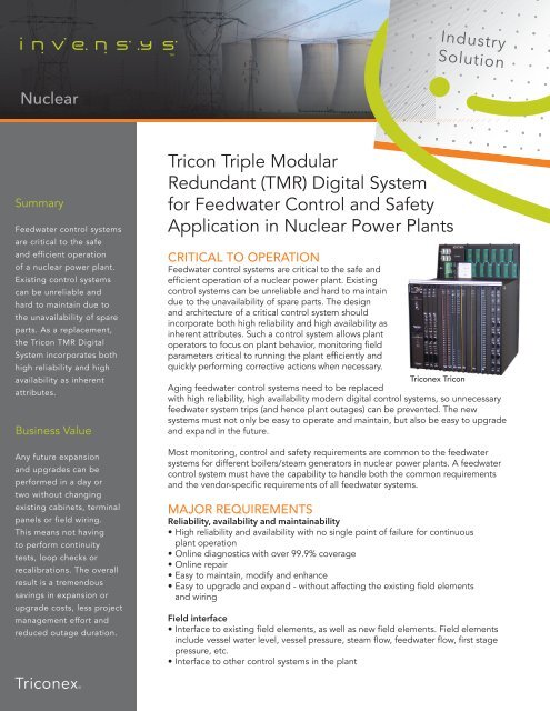
CRITICAL TO OPERATION<br />
Feedwater control systems are critical to the safe and<br />
efficient operation of a nuclear power plant. Existing<br />
control systems can be unreliable and hard to maintain<br />
due to the unavailability of spare parts. The design<br />
and architecture of a critical control system should<br />
incorporate both high reliability and high availability as<br />
inherent attributes. Such a control system allows plant<br />
operators to focus on plant behavior, monitoring field<br />
parameters critical to running the plant efficiently and<br />
quickly performing corrective actions when necessary.<br />
<strong>Tricon</strong>ex <strong>Tricon</strong><br />
Aging feedwater control systems need to be replaced<br />
with high reliability, high availability modern digital control systems, so unnecessary<br />
feedwater system trips (and hence plant outages) can be prevented. The new<br />
systems must not only be easy to operate and maintain, but also be easy to upgrade<br />
and expand in the future.<br />
Most monitoring, control and safety requirements are common to the feedwater<br />
systems for different boilers/steam generators in nuclear power plants. A feedwater<br />
control system must have the capability to handle both the common requirements<br />
and the vendor-specific requirements of all feedwater systems.<br />
MAJOR REQUIREMENTS<br />
Reliability, availability and maintainability<br />
• High reliability and availability with no single point of failure for continuous<br />
plant operation<br />
• Online diagnostics with over 99.9% coverage<br />
• Online repair<br />
• Easy to maintain, modify and enhance<br />
• Easy to upgrade and expand - without affecting the existing field elements<br />
and wiring<br />
Field interface<br />
• Interface to existing field elements, as well as new field elements. Field elements<br />
include vessel water level, vessel pressure, steam flow, feedwater flow, first stage<br />
pressure, etc.<br />
• Interface to other control systems in the plant
Control, safety and test<br />
• Maintain water level in the vessel within a pre-defined range (setpoint ± a specified value) by<br />
maintaining steam flow out/water flow in mass balance under dynamic load conditions<br />
• Implement existing automatic or manual operational procedures and control strategies<br />
• Implement a combination of single-element/three-element auto control and manual control<br />
strategies, with bumpless switching between strategies. Single-element control uses only water level<br />
as an input; three-element control uses water level, steamflow and feedwater flow as inputs<br />
• Detect unsafe plant conditions and safely shut the system down<br />
Operator interface<br />
• Easy to use operator interface for monitoring and control<br />
• Enhanced visibility of critical feedwater parameters in real time<br />
• Allow the operator to set the following control parameters: Setpoint for the vessel water level, Bypass<br />
for individual input signals, Reset for individual alarms, Auto/Manual control mode, Ramp Rate Hi/<br />
Med/Slow, etc.<br />
• Easy to navigate between control, monitoring and maintenance screens<br />
Communications<br />
• Ability to interface with existing plant computer and DCS system<br />
• <strong>Redundant</strong>, high speed, industry standard communication interfaces and protocols to transfer realtime<br />
data (feedwater system parameters, field status, alarms, trips, system status, field inputs and<br />
outputs, etc.) for control, monitoring, logging and trending for field diagnostic purposes<br />
TRICON-BASED FEEDWATER CONTROL SYSTEM ARCHITECTURE<br />
The <strong>Tricon</strong>-based feedwater control system architecture is shown in Figure 1 on the next page.<br />
This basic architecture can be adapted to satisfy existing plant-specific field elements and wiring<br />
requirements, any additional field element requirements, existing auto-manual feedwater control<br />
procedures and strategies and communication requirements.<br />
A typical feedwater control system consists of:<br />
• <strong>Tricon</strong>ex ® <strong>Tricon</strong> <strong>TMR</strong> system<br />
• <strong>Tricon</strong>ex TriStation 1131 application development station<br />
• Feedwater control application software<br />
• Foxboro I/A Series ® <strong>System</strong> or Wonderware ® HMI (Human Machine Interface)<br />
• Maintenance/Engineering workstation<br />
• TriLogger software<br />
<strong>Tricon</strong> <strong>TMR</strong> system<br />
The <strong>Tricon</strong> is a <strong>Triple</strong> Module <strong>Redundant</strong> (<strong>TMR</strong>) architecture-based digital safety and control system.<br />
The system is certified by TÜV (a world recognized, independent safety agency) at IEC (International<br />
Electrotechnical Commission) SIL (Safety Integrity Level) 3 to be used for safety and critical control<br />
applications in process control and other industries. The <strong>Tricon</strong> is also certified by the NRC (Nuclear<br />
Regulatory Commission) to be used for safety (1E) and critical control applications in nuclear power plants.<br />
The <strong>Tricon</strong> has three independent channels from the input terminal to the output terminal. Each input<br />
is voted every scan by the three main processors (MPs), and the resultant voted input is provided to<br />
the same application running in the three MPs. The outputs from the application running in each MP<br />
go to the output modules where they are voted. The resultant voted output for each point goes to the<br />
output terminal/field device.<br />
The <strong>TMR</strong> architecture and design allows the <strong>Tricon</strong> system to perform its intended safety and control<br />
functions in the presence of a single hardware fault. In addition, the design allows the <strong>Tricon</strong> to run in<br />
<strong>TMR</strong>, DUAL or SINGLE mode, thus providing high availability (99.99%).
Figure 1 − <strong>Tricon</strong>-Based Feedwater Control <strong>System</strong> Architecture<br />
The built-in online diagnostics provide more than 99.9% fault coverage and isolate a fault to a specific<br />
module. The faulted module can be replaced with a new module online without affecting the feedwater<br />
system operation. The <strong>Tricon</strong> combines technology and architecture features to provide safety and<br />
control functions with the high reliability and high availability required for the safety and critical control<br />
applications in nuclear power plants.<br />
The <strong>Tricon</strong> can be expanded from a single chassis system all the way up to a 15 chassis system with a<br />
wide variety of I/O and communications (COM) modules. Most feedwater control systems require a main<br />
chassis and two to three I/O expansion chassis, depending on the number of field elements and spare slot<br />
requirements for future expansion.<br />
The COM modules provide the <strong>Tricon</strong> with the ability to interface to the existing plant computer, DCS<br />
systems, operator stations, etc. These COM modules provide the redundant, high speed, industry<br />
standard communication interfaces and protocols for transferring real-time plant data for control,<br />
monitoring, logging and trending for field diagnostics purposes. The I/O modules allow the <strong>Tricon</strong> to<br />
interface to different types of new and existing field devices. The I/O modules include: Analog Input,<br />
Analog Output, Thermocouple, Pulse Input, <strong>Digital</strong> Input and <strong>Digital</strong> Output.
TriStation 1131 Workstation<br />
TriStation 1131 is a PC-based safety and critical process control application development workstation that<br />
provides a comprehensive set of development, test, monitor, validation and diagnostic tools for <strong>Tricon</strong>ex<br />
Programmable Safety <strong>System</strong>s (<strong>Tricon</strong> and Trident). TriStation 1131 is compliant with the IEC 1131-3<br />
International Standard for Programmable Controllers, Part 3: Programming Languages.<br />
TriStation 1131 includes the following major features for application development:<br />
• IEC programming languages: Structured Text (ST) language (textual language), Function Block<br />
Diagram (FBD) Language (graphical language) and Ladder Diagram (LD) Language (graphical<br />
language);<br />
• IEC data types: Basic data types (BOOL, INT, DINT, REAL, LREAL, DWORD, STRING, TIME, TOD,<br />
DATE and DT) and user-derived data types (ARRAY, STRUCT, CONSTANT and ENUMERATION);<br />
• Ready-made, thoroughly tested libraries for application development:<br />
− IEC standard library<br />
− <strong>Tricon</strong>ex library: system status and diagnostics functions, Scheduler functions, PID functions,<br />
Sequence Of Events (SOE) functions<br />
− Feedwater control libraries: Special feedwater control functions developed by the domain experts at<br />
<strong>Tricon</strong>ex, based on 20 years of experience in control system design and development<br />
• User-defined libraries: Users can develop, test and archive their own libraries to be used in different<br />
applications<br />
• Easy to use Windows-based graphical user interface<br />
• A browser-based help system with help for TriStation 1131 operations, library functions and error<br />
messages<br />
• Security features and audit trail<br />
• Built-in application change control and version control<br />
• Emulator for application testing prior to downloading to the <strong>Tricon</strong> system<br />
• Project execution monitoring and control<br />
• Comment boxes and variable annotation for in-line documentation<br />
Feedwater Control Application Software<br />
Critical control application software is developed using the TriStation 1131 workstation and associated<br />
standard, as well as feedwater control application specific libraries. See the critical application<br />
software architecture.<br />
Foxboro I/A Series <strong>System</strong> or Wonderware HMI<br />
The Foxboro I/A Series <strong>System</strong> or Wonderware InTouch ® HMI provide a graphical, easy to use operator<br />
interface for the control and monitoring of turbine operation. In addition, they provide real-time data,<br />
alarms and event logging capabilities.<br />
Standard feedwater control and monitoring screens are available for both workstations. The standard<br />
screens can be modified and additional screens can be easily developed to meet the nuclear plant’s<br />
operational requirements.<br />
Maintenance/Engineering workstation<br />
This is a commercial off-the-shelf ruggedized PC with the <strong>Tricon</strong> Diagnostic Monitor utility installed.<br />
This utility displays <strong>Tricon</strong> system and module status by mimicking the actual <strong>Tricon</strong> chassis and<br />
slots, so that the user can find the exact location (chassis number and slot number) of a module. This<br />
workstation may also include the TriStation 1131 application software and TriLogger software.<br />
TriLogger<br />
The TriLogger software provides the ability to record, display, playback and analyze the field data<br />
from the <strong>Tricon</strong> system. Data can be viewed in real-time, either locally or remotely. Data trending and<br />
analysis capabilities help diagnose field problems.
CRITICAL APPLICATION SOFTWARE ARCHITECTURE<br />
Critical application software architecture consists of standard, off-the-shelf software modules (programs,<br />
functions and function blocks) developed using TriStation 1131 and associated libraries. The flexibility<br />
of the feedwater control application architecture, combined with the TriStation 1131 programming<br />
facilities and the expertise and experience of the <strong>Tricon</strong>ex personnel, makes it easy to adapt the<br />
architecture to satisfy any plant-specific feedwater control strategy and procedures.<br />
The software implements the feedwater operational states (modes) and the specific control and monitoring<br />
functions in each state, based on the feedwater system status received from the field and inputs from the<br />
operator station (HMI). Figure 2 shows the feedwater system states and state transition.<br />
Figure 2 − Feedwater <strong>System</strong> States and State Transition Diagram<br />
Figure 3 shows the major software modules and their interrelationships. These modules implement the<br />
field inputs processing, operator inputs processing, feedwater system states and control strategy.<br />
Figure 3 − Feedwater Control Application Software Architecture
The Vessel_Water_Level, Steam_Flow and Feedwater_Flow modules process field and operator inputs.<br />
Each module scales the inputs, validates the inputs and selects median, average, single or zero value<br />
based on the number of valid inputs for each input type. The Feedwater <strong>System</strong> States and Control<br />
Strategy module implements the system states and associated control functions in each state:<br />
Field Manual State<br />
This state is entered on cold/warm start and when any one of the field auto_manual signals from the<br />
valves servo controllers or feedwater pump control system goes off. The operator controls feedwater<br />
flow manually from the servo controllers for the valves and the feedwater pump control system. In this<br />
mode, the application disables the demand signals to the field (i.e., sends zero to the servo controllers<br />
and feedwater pump control system). This state is exited when the field auto_manual signals from the<br />
servo controllers and the feedwater pump control system become true.<br />
Local Automatic/Manual<br />
This state is entered when the current state is Field Manual and the field auto_manual signals from the<br />
servo controllers and the feedwater pump control system are true. This state is also entered when one<br />
of the following occurs:<br />
• The Local Auto mode flag is set by the operator<br />
• A loss of feedwater flow is detected in single-element or three-element control mode<br />
• A loss of vessel water level is detected in single-element or three-element control mode<br />
The operator controls the feedwater flow from the HMI through the <strong>Tricon</strong> system. From the HMI, the<br />
operator can set the system in a remote mode by setting the remote mode flag on. This state is exited<br />
when any one of the field auto-manual signals goes off or when the remote mode flag is set by the<br />
operator and the prerequisites (field conditions) for the single- element control mode are satisfied.<br />
Single-Element (Water Level)<br />
This state is entered when the current state is Local Automatic/Manual, the remote mode flag is set by<br />
the operator and the prerequisites (field conditions) for the single-element control mode are satisfied.<br />
In this mode, the water level target (setpoint) is compared to the actual vessel water level to generate<br />
an error signal. This error signal is processed by the Proportional-Integral-Derivative (PID) function to<br />
generate the demand signal (setpoint) for the feedwater flow controller’s PID. Gain and integral settings<br />
for the PID are derived from the adaptive tuning parameters across the full spectrum of power band for<br />
optimum level control. The single-element control is used for low load condition (power level less than<br />
16% of full power). The first stage pressure input is used to estimate the current power level. Refer to<br />
Figure 4 for an example of single-element and three-element control strategies.<br />
This state is exited when any of the following occurs:<br />
• One of the auto-manual signals goes off<br />
• A loss of vessel water level or feedwater flow is detected<br />
• The Local Auto mode flag is set by the operator<br />
• The power level is greater than or equal to 16% and the prerequisites (field conditions) for the threeelement<br />
auto mode are satisfied<br />
Three-Element (Water Level, Steam Flow and Feedwater Flow)<br />
This state is entered when the current state is Single-Element and the prerequisites (field conditions) for<br />
the three-element control mode are satisfied.
In this mode, the water level target (setpoint) is compared to the actual vessel water level input to<br />
generate an error signal. This error signal is processed by the Proportional-Integral-Derivative (PID)<br />
function to generate the demand signal. This demand signal is combined with the steam flow input<br />
to generate a setpoint for the feedwater controller’s PID. This setpoint is compared to the feedwater<br />
flow input. The resultant error signal (feedwater flow error) is the demand signal for the field control<br />
elements. The gain and integral settings for the PIDs are derived from the adaptive tuning parameters<br />
across the power band for optimum level control.<br />
The system automatically switches between single-element and three-element control mode<br />
depending upon the plant conditions. Once in three-element control mode, the system remains in that<br />
mode as long as there is at least one valid input for the water level, steam flow and feedwater flow.<br />
Figure 4 shows one of the various ways of implementing control strategy. <strong>Invensys</strong> has implemented<br />
different strategies for different nuclear power plants, based on plant-specific control requirements.<br />
This state is exited when any of the following occurs:<br />
• The auto-manual signals goes off<br />
• A loss of vessel water level, a loss of steam flow or a loss of feedwater flow is detected<br />
• The Local Auto mode flag is set by the operator<br />
• The power level is less than 14% of full power<br />
Figure 4 − Detailed Single-element and Three-element Control Strategy
OPERATOR SCREENS<br />
The feedwater control and monitoring screens listed below are available for both the I/A Series<br />
workstation and the Wonderware workstation. These standard screens are provided with programmable<br />
security levels and can be modified to meet a particular nuclear plant’s operational requirements.<br />
Additional screens can also be easily developed.<br />
• Feedwater Overview screen<br />
• Control screen<br />
• Alarms screen<br />
• Maintenance screen<br />
• Field I/O screen<br />
SUMMARY<br />
The <strong>Tricon</strong> is a high reliability, high availability<br />
(99.99%), digital feedwater control system<br />
with no single point of failure. The built-in<br />
features (high reliability, high availability, low<br />
maintenance, self-calibration, built-in online<br />
diagnostics, online repair, easy to expand and<br />
upgrade) help reduce life cycle operations and<br />
maintenance costs.<br />
<strong>Invensys</strong> Operations Management • 5601 Granite Parkway III, #1000, Plano, TX 75024 • Tel: (469) 365-6400 • Fax: (469) 365-6401 • iom.invensys.com<br />
<strong>Invensys</strong>, the <strong>Invensys</strong> logo, ArchestrA, Avantis, Eurotherm, Foxboro, IMServ, InFusion, SimSci-Esscor, Skelta, <strong>Tricon</strong>ex, and Wonderware are trademarks of <strong>Invensys</strong> plc, its subsidiaries or affiliates.<br />
All other brands and product names may be the trademarks or service marks of their representative owners.<br />
© 2011 <strong>Invensys</strong> <strong>System</strong>s, Inc. All rights reserved. No part of the material protected by this copyright may be reproduced or utilized in any form or by any means, electronic or mechanical, including<br />
photocopying, recording, broadcasting, or by any information storage and retrieval system, without permission in writing from <strong>Invensys</strong> <strong>System</strong>s, Inc.<br />
Rel. 02/11 PN I-NC-0101<br />
The online diagnostics provide more than<br />
99.9% diagnostic coverage, providing a basis<br />
to reduce periodic surveillance testing between<br />
refueling cycles. Online repair increases<br />
availability even further.<br />
When you install the <strong>Tricon</strong>, you get the<br />
experience and knowledge of the <strong>Tricon</strong>ex<br />
feedwater control domain experts. You also gain<br />
<strong>Invensys</strong>’ experience in design, development,<br />
installation and support of the feedwater<br />
control system, efficient project execution and<br />
integration capabilities, round-the-clock customer<br />
support and customized training for the I&C and<br />
plant operation personnel.<br />
Any future expansion and upgrades can be performed in a day or two without changing existing<br />
cabinets, terminal panels or field wiring. This means not having to perform continuity tests, loop checks<br />
or recalibrations. The overall result is a tremendous savings in expansion or upgrade costs,<br />
less project management effort and reduced outage duration.


![[MI 019-179] Veiligheidsinformatie stromingsproducten - Invensys](https://img.yumpu.com/19988828/1/190x245/mi-019-179-veiligheidsinformatie-stromingsproducten-invensys.jpg?quality=85)