72 Series Monitoring relays 6 - Finder
72 Series Monitoring relays 6 - Finder
72 Series Monitoring relays 6 - Finder

Create successful ePaper yourself
Turn your PDF publications into a flip-book with our unique Google optimized e-Paper software.
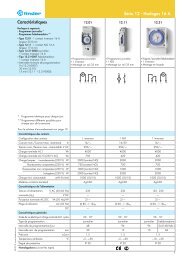
IX-2012, www.findernet.com<br />
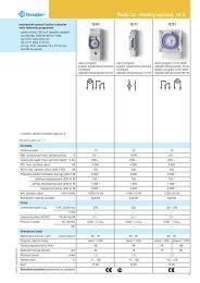
Features<br />
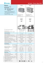
Level control <strong>relays</strong> for conductive liquids<br />
<strong>72</strong>.01 - Adjustable sensitivity<br />
<strong>72</strong>.11 - Fixed sensitivity<br />
• Emptying or filling functions<br />
• LED indicator<br />
• Reinforced insulation (6 kV - 1.2/50 μs) between:<br />
- supply and contacts<br />
- electrodes and supply<br />
- contacts and electrodes<br />
• 35 mm rail (EN 60715) mount<br />
• Control about a single level or between<br />
Min./Max. limits<br />
• <strong>72</strong>.01 available also for supply 400 V<br />
• <strong>72</strong>.01 available also with sensitivity range<br />
(5...450) kΩ adjustable<br />
• <strong>72</strong>.01 available also for contact loads down<br />
to 5 V 1 mA<br />
FOR UL RATINGS SEE:<br />
“General technical information” page V<br />
For outline drawing see page 8<br />
Contact specification<br />
Contact configuration<br />
Rated current/Maximum peak current A<br />
Rated voltage/Maximum switching voltage V AC<br />
Rated load AC1 VA<br />
Rated load AC15 (230 V AC) VA<br />
Single phase motor rating (230 V AC) kW<br />
Breaking capacity DC1: 30/110/220 V A<br />
Minimum switching load<br />
Standard contact material<br />
Supply specification<br />
mW (V/mA)<br />
Nominal voltage (UN) V AC<br />
V DC<br />
Rated power AC/DC VA (50 Hz)/W<br />
Operating range<br />
Technical data<br />
AC<br />
DC<br />
Electrical life at rated load AC1 cycles<br />
Electrode voltage V AC<br />
Electrode current mA<br />
Run-on time s<br />
Max sensitivity range kΩ<br />
Insulation between supply/contacts/electrode (1.2/50 μs) kV<br />
Ambient temperature °C<br />
Protection category<br />
Approvals (according to type)<br />
• Sensitivity range (5...150) kΩ adjustable<br />
• Delay time (0.5s or 7s) switch selectable<br />
• Emptying or filling functions switch selectable<br />
U = 24 V DC<br />
24 V AC 50/60 Hz<br />
(110...125)V AC 50/60 Hz<br />
(230...240)V AC 50/60 Hz<br />
FL = Filing – 7s delay<br />
FS = Filling – 0.5s delay<br />
ES = Emptying – 0.5s delay<br />
EL = Emptying – 7s delay<br />
<strong>72</strong> <strong>Series</strong> - <strong>Monitoring</strong> <strong>relays</strong><br />
<strong>72</strong>.01 <strong>72</strong>.11<br />
• Sensitivity fixed 150 kΩ<br />
• Delay time fixed: 1s<br />
• Emptying or filling functions link selectable<br />
U = 24 V DC<br />
24 V AC 50/60 Hz<br />
(110...125)V AC 50/60 Hz<br />
(230...240)V AC 50/60 Hz<br />
1 CO (SPDT) 1 CO (SPDT)<br />
16/30 16/30<br />
250/400 250/400<br />
4,000 4,000<br />
750 750<br />
0.55 0.55<br />
16/0.3/0.12 16/0.3/0.12<br />
500 (10/5) 500 (10/5)<br />
AgCdO AgCdO<br />
24 - 110...125 – 230...240 400 24 - 110...125 – 230...240<br />
24 — 24<br />
2.5/1.5 2.5/1.5 2.5/1.5<br />
(0.8...1.1)UN (0.9...1.15)UN (0.8...1.1)UN (0.85...1.1)UN — (0.85...1.1)UN 100 · 10 3<br />
100 · 10 3<br />
4 4<br />
0.2 0.2<br />
0.5 - 7 (selectable) 1<br />
5…150 (adjustable) 150 (fixed)<br />
6 6<br />
–20…+60 –20…+60<br />
IP20 IP20<br />
F = Filling<br />
E = Emptying<br />
1
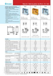
Features<br />
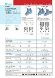
Priority change relay<br />
Special relay for alternating loads,<br />
for applications with pumps, compressors,<br />
air conditioning or refrigeration units<br />
• 2 independent NO output, 12 A<br />
• 4 functions<br />
• 2 independent control signals, insulated from<br />
supply<br />
• 110...240 V and 24 V AC/DC supply versions<br />
• Modular housing, 35 mm wide<br />
• 35 mm rail (EN 60715) mount<br />
• Cd-free contact material<br />
Screw terminal<br />
For outline drawing see page 8<br />
Contact specification<br />
Contact configuration<br />
Rated current / Max. peak current A<br />
Rated voltage / Max. switching voltage V AC (50/60 Hz)<br />
Rated load AC1 VA<br />
Rated load AC15 VA<br />
Single phase motor rating (230 V AC) kW<br />
Breaking capacity DC1: 30/110/220 V A<br />
Minimum switching load mW (V/mA)<br />
Standard contact material<br />
Supply specification<br />
Nominal voltage (UN) V AC (50/60 Hz) / DC<br />
Rated power in stand-by W<br />
with 2 active <strong>relays</strong> W/VA(50 Hz)<br />
Operating range V AC (50/60 Hz)<br />
V DC<br />
Technical data<br />
Electrical life at rated load AC1 cycles<br />
Output delay time (T on function diagrams) s<br />
Power-on activation time s<br />
Minimum impulse duration ms<br />
Insulation between supply and contacts (1.2/50 μs) kV<br />
Dielectric strength between open contacts V AC<br />
Ambient temperature °C<br />
Protection category<br />
Approvals (according to type)<br />
2<br />
<strong>72</strong>.42<br />
• Multi-function (MI, ME, M2, M1)<br />
2 NO (2 DPST-NO)<br />
12 / 20<br />
250 / 400<br />
3,000<br />
1,000<br />
0.55<br />
12 / 0.3 / 0.12<br />
300 (5 / 5)<br />
AgNi<br />
24 110 … 240<br />
0.12 0.18<br />
1.1 / 1.7 1.5 / 3.9<br />
16.8…28.8 90…264<br />
16.8…32 90…264<br />
100 x 10 3<br />
0.2...20<br />
≤ 0.7<br />
50<br />
6<br />
1,000<br />
–20…+50<br />
IP20<br />
<strong>72</strong> <strong>Series</strong> - <strong>Monitoring</strong> <strong>relays</strong><br />
IX-2012, www.findernet.com
IX-2012, www.findernet.com<br />
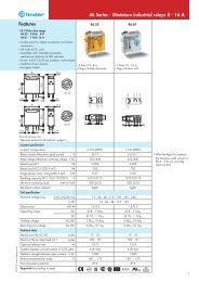
Ordering information<br />
Example: <strong>72</strong> series level control relay, adjustable sensitivity range, (230…240)V AC supply voltage.<br />
7 2<br />
<strong>Series</strong><br />
Type<br />
0 = Level control relay,<br />
sensitivity range adjustable (5...150)kΩ<br />
1 = Level control relay, sensitivity fixed 150 kΩ<br />
4 = Priority change relay<br />
No. of poles<br />
1 = 1 CO (SPDT)<br />
2 = 2 NO (DPST-NO)<br />
. 0 1 . 8 . 2 4 0 . 0 0 0 0<br />
<strong>72</strong> <strong>Series</strong> - <strong>Monitoring</strong> <strong>relays</strong><br />
Contact material<br />
0 = Standard (AgCdO)<br />
5 = AgNi + Au (5 μm)<br />
Supply voltage<br />
024 = 24 V<br />
125 = (110…125)V AC<br />
230 = (110 … 240) V<br />
240 = (230…240)V AC<br />
400 = 400 V AC (<strong>72</strong>.01 only)<br />
Supply version<br />
0 = DC / AC (50/60 Hz)<br />
8 = AC (50/60 Hz)<br />
9 = DC<br />
All versions<br />
<strong>72</strong>.01.8.024.0000<br />
<strong>72</strong>.01.8.024.0002*<br />
<strong>72</strong>.01.8.125.0000<br />
<strong>72</strong>.01.8.240.0000<br />
<strong>72</strong>.01.8.240.0002*<br />
<strong>72</strong>.01.8.240.5002**<br />
<strong>72</strong>.01.8.400.0000<br />
<strong>72</strong>.01.9.024.0000<br />
<strong>72</strong>.11.8.024.0000<br />
<strong>72</strong>.11.8.125.0000<br />
<strong>72</strong>.11.8.240.0000<br />
<strong>72</strong>.11.9.024.0000<br />
<strong>72</strong>.42.0.230.0000<br />
<strong>72</strong>.42.0.024.0000<br />
Option<br />
2 = Sensitivity range<br />
adjustable (5...450) kΩ<br />
types <strong>72</strong>.01.8.024.0002<br />
<strong>72</strong>.01.8.240.0002* and<br />
<strong>72</strong>.01.8.240.5002**<br />
* For liquids conductivity up to 2 μSiemens<br />
or a Resistance of 450 kOhms<br />
** For applications with output contact loading down to 5 V<br />
1 mA<br />
3
Technical data<br />
4<br />
<strong>72</strong> <strong>Series</strong> - <strong>Monitoring</strong> <strong>relays</strong><br />
Insulation <strong>72</strong>.01/<strong>72</strong>.11 <strong>72</strong>.42<br />
Insulation Dielectric strength Impulse (1.2/50 μs)<br />
between supply and contacts 4,000 V AC 6 kV 6 kV<br />
between supply and control (for 110…240 V version only) 2,500 V AC — 4 kV<br />
between electrodes, Z1-Z2 and supply* 4,000 V AC 6 kV —<br />
between contacts and electrodes 4,000 V AC 6 kV —<br />
between open contacts<br />
EMC specifications<br />
1,000 V AC 1.5 kV 1.5 kV<br />
Type of test Reference standard <strong>72</strong>.01/<strong>72</strong>.11 <strong>72</strong>.42<br />
Electrostatic discharge contact discharge EN 61000-4-2 4 kV 4 kV<br />
air discharge EN 61000-4-2 8 kV 8 kV<br />
Radio-frequency electromagnetic field (80...1,000 MHz) EN 61000-4-3 10 V/m 10 V/m<br />
(1…2.8 GHz) EN 61000-4-3 — 5 V/m<br />
Fast transients on supply terminals EN 61000-4-4 4 kV 4 kV<br />
(burst 5/50 ns, 5 and 100 kHz) on control terminals EN 61000-4-4 — 4 kV<br />
Voltage pulses on supply terminals common mode EN 61000-4-5 4 kV 4 kV<br />
(surge 1.2/50 μs) differential mode EN 61000-4-5 4 kV 4 kV<br />
Radiofrequency common mode on supply terminals EN 61000-4-6 10 V 10 V (0.15...230 MHz)<br />
voltage (0.15…280 MHz) on control terminals EN 61000-4-6 — 10 V<br />
Voltage dips 70 % U N EN 61000-4-11 — 25 cycles<br />
Short interruptions EN 61000-4-11 — 1 cycles<br />
Radiofrequency conducted emissions (0.15…30 MHz) CISPR 11 class B class B<br />
Radiated emissions<br />
Terminals<br />
(30…1,000 MHz) CISPR 11 class B class B<br />
Screw torque Nm 0.8<br />
Wire strip length mm 9<br />
Max. wire size solid cable stranded cable<br />
mm 2 1x6 / 2x4 1x4 / 2x2.5<br />
AWG 1x10 / 2x12 1x12 / 2x14<br />
Other data<br />
Current absorption on Z1 and Z2 (type <strong>72</strong>.11) mA < 1<br />
Current absorption on control signal (B1-B3 and B2-B3) 5 mA, 5 V<br />
Power lost to the environment <strong>72</strong>.01/<strong>72</strong>.11 <strong>72</strong>.42<br />
without contact current W 1.5 0.9 (1 relay ON)<br />
with rated current W 3.2 3.0 (2 <strong>relays</strong> ON)<br />
Max cable length between electrode and relay (types <strong>72</strong>.01/<strong>72</strong>.11) m 200 (max. capacitance of 100 nF/km)<br />
*There is no electrical isolation between electrodes and supply voltage for the 24 V DC types (<strong>72</strong>.x1.9.024.0000). Therefore, for SELV<br />
applications it would be necessary to use a SELV (non-grounded) power supply. In the case of a PELV (grounded) power supply take care to<br />
protect the level control relay against harmful circulating currents by ensuring that no electrodes are grounded.<br />
However, there is no such problem for the 24 V AC types (<strong>72</strong>.x1.8.024.0000) which, by virtue of an internal isolating transformer, assure<br />
reinforced isolation between electrodes and supply.<br />
IX-2012, www.findernet.com
IX-2012, www.findernet.com<br />
Functions for <strong>72</strong>.01 and <strong>72</strong>.11<br />
U = Supply voltage<br />
B1 = Max level<br />
electrode<br />
B2 = Min level<br />
electrode<br />
B3 = Common<br />
= Contact 11-14<br />
Z1-Z2 = Link to select<br />
emptying<br />
(Type <strong>72</strong>.11)<br />
Function and Run-on time<br />
LED<br />
Supply<br />
voltage<br />
OFF<br />
ON<br />
ON<br />
ON<br />
<strong>72</strong> <strong>Series</strong> - <strong>Monitoring</strong> <strong>relays</strong><br />
NO output<br />
contact<br />
Open<br />
Open<br />
Open<br />
(Timing in Progress)<br />
Closed<br />
Contacts<br />
Open Closed<br />
11 - 14<br />
11 - 14<br />
11 - 14<br />
11 - 12<br />
11 - 12<br />
11 - 12<br />
11 - 12<br />
11 - 14<br />
Type <strong>72</strong>.01 Type <strong>72</strong>.11<br />
FL = Level control by Filling, Long (7sec) run-on delay. F = Level control by Filling, Z1–Z2 open. Run-on time fixed at 1sec.<br />
FS = Level control by Filling, Short (0.5sec) run-on delay. E = Level control by Emptying, Z1–Z2 linked. Run-on time fixed at 1sec.<br />
ES = Level control by Emptying, Short (0.5sec) run-on delay.<br />
EL = Level control by Emptying, Long (7sec) run-on delay.<br />
Filling functions<br />
Wiring diagram Examples with 3 electrodes<br />
Type <strong>72</strong>.01 Filling Control – between Min.<br />
Type <strong>72</strong>.11<br />
Wiring diagram Examples with 2 electrodes<br />
and Max. levels.<br />
Under normal operation the liquid<br />
level can be expected to cycle<br />
between the Minimum and the<br />
Maximum electrodes, B2 and B1<br />
(plus a degree of over and<br />
under-shoot).<br />
Switch On:<br />
• On “power-up”, if the liquid is<br />
below B1 the output relay will<br />
operate after time T has expired.<br />
• On the liquid level falling below<br />
B2, the output relay will operate<br />
after time T has expired.<br />
Switch Off:<br />
• On the liquid level reaching<br />
electrode B1, the output relay will<br />
de-energise after time T has<br />
expired.<br />
• On “power-off”, the output relay<br />
will immediately de-energise.<br />
Type <strong>72</strong>.01 Filling Control – about a single<br />
Type <strong>72</strong>.11<br />
U = 24 V DC<br />
24 V AC 50/60 Hz<br />
(110...125)V AC 50/60 Hz<br />
(230...240)V AC 50/60 Hz<br />
F = Filling<br />
U = 24 V DC<br />
24 V AC 50/60 Hz<br />
(110...125)V AC 50/60 Hz<br />
(230...240)V AC 50/60 Hz<br />
F = Filling<br />
Level<br />
Level<br />
level, B1.<br />
Under normal operation the liquid<br />
evel can be expected to cycle about<br />
the level set by electrode B1 with a<br />
degree of over and under-shoot.<br />
Switch On:<br />
• On “power-up”, if the liquid is<br />
below B1 the output relay will<br />
operate after time T has expired.<br />
• On the liquid level falling below<br />
B1, the output relay will operate<br />
after time T has expired.<br />
Switch Off:<br />
• On the liquid level reaching<br />
electrode B1, the output relay will<br />
de-energise after time T has expired.<br />
• On “power-off”, the output relay<br />
will immediately de-energise.<br />
5
Emptying functions<br />
Wiring diagram Examples with 3 electrodes<br />
Type <strong>72</strong>.01<br />
Type <strong>72</strong>.11<br />
Emptying Control – between Max.<br />
and Min. levels.<br />
Under normal operation the liquid<br />
level can be expected to cycle<br />
between the Maximum and the<br />
Minimum electrodes, B1 and B2 (plus<br />
a degree of over and under-shoot).<br />
Switch On:<br />
On “power-up”, if the liquid level<br />
is above B2 the output relay will<br />
operate after time T has expired.<br />
On the liquid level rising to B1, the<br />
output relay will operate after time T<br />
has expired.<br />
Switch Off:<br />
On the liquid level falling below<br />
electrode B2, the output relay will<br />
de-energise after time T has expired.<br />
On “power-off”, the output relay<br />
will immediately de-energise.<br />
Type <strong>72</strong>.01 Emptying Control about a single level,<br />
Type <strong>72</strong>.11<br />
U = 24 V DC<br />
24 V AC 50/60 Hz<br />
(110...125)V AC 50/60 Hz<br />
(230...240)V AC 50/60 Hz<br />
E = Emptying<br />
U = 24 V DC<br />
24 V AC 50/60 Hz<br />
(110...125)V AC 50/60 Hz<br />
(230...240)V AC 50/60 Hz<br />
E = Emptying<br />
Level<br />
Wiring diagram Examples with 2 electrodes<br />
6<br />
Level<br />
Applications for <strong>72</strong>.01 and <strong>72</strong>.11<br />
FILLING function:<br />
Examples with 3 electrodes and with a<br />
contactor connected to the contact.<br />
EMPTYING function:<br />
Examples with 3 electrodes and with a motor<br />
pump connected directly to the contact.<br />
<strong>72</strong> <strong>Series</strong> - <strong>Monitoring</strong> <strong>relays</strong><br />
B1.<br />
Under normal operation the liquid<br />
level can be expected to cycle about<br />
the level set by electrode B1 with a<br />
degree of over and under-shoot.<br />
Switch On:<br />
On “power-up”, if the liquid is<br />
above B1 the output relay will<br />
operate after time T has expired.<br />
On the liquid level rising to B1, the<br />
output relay will operate after time T<br />
has expired.<br />
Switch Off:<br />
On the liquid level falling below<br />
electrode B1, the output relay will<br />
de-energise after time T has expired.<br />
On “power-off”, the output relay<br />
will immediately de-energ<br />
The <strong>72</strong> series level control <strong>relays</strong> work by<br />
measuring the resistance through the liquid,<br />
between the common (B3) electrode and Min. and<br />
Max. electrodes (B2 and B1). If the tank is metalic,<br />
then this can be substituted as the B3 electrode.<br />
Take care to ensure that the liquid has a<br />
suitable resistivity – see below:<br />
SUITABLE LIQUIDS<br />
- City water<br />
- Well water<br />
- Rainwater<br />
- Sea water<br />
- Liquids with low-percentage alcohol<br />
- Wine<br />
- Milk, Beer, Coffee<br />
- Sewage<br />
- Liquids fertilizer<br />
UN-SUITABLE LIQUIDS<br />
- Demineralised water<br />
- Fuels<br />
- Oil<br />
- Liquids with high-percentage alcohol<br />
- Liquid gas<br />
- Paraffins<br />
- Ethylene glycol<br />
- Paint<br />
IX-2012, www.findernet.com
IX-2012, www.findernet.com<br />
Functions for <strong>72</strong>.42<br />
A1-A2 = Supply voltage<br />
S1 (B1-B2) = Control signal 1<br />
S2 (B3-B2) = Control signal 2<br />
= Contact 1 (11-14) and<br />
Contact 2 (21-24)<br />
LED 1 = Output 1<br />
LED 2 = Output 2<br />
Wiring diagram<br />
LED<br />
<strong>72</strong> <strong>Series</strong> - <strong>Monitoring</strong> <strong>relays</strong><br />
Device in stand-by, output not activated<br />
Output not activated, timing in progress<br />
Output not activated (only functions M1/M2)<br />
Output activated<br />
(MI) Outputs alternate on successive applications of<br />
supply voltage<br />
• Application of the supply voltage to A1-A2 forces<br />
just one output contact to close, but the contact that<br />
closes will alternate between 11-14 and 21-24 on<br />
each successive application of the supply – ensuring<br />
even wear across both motors.<br />
• The other output contact can be forced closed by the<br />
closure of either S1 or S2 - but to limit high current<br />
surges the other motor cannot start within T seconds of<br />
the first motor.<br />
(ME) Outputs alternate according to control signal<br />
• The supply voltage is permanently applied to A1-A2.<br />
When closed, S1 forces just one output contact to<br />
close. The contact that closes will alternate between<br />
11-14 and 21-24 on each successive S1 closure -<br />
ensuring even wear across both motors.<br />
• If closed, S2 forces both output contacts to close<br />
(irrespective of S1). However, to limit high current<br />
surges, both motors cannot start within T seconds of<br />
each other.<br />
(M2) Output 2 (21-24) only<br />
• Supply permanently applied to A1-A2.<br />
• Closure of either S1 or S2 will close output contact<br />
2 (21-24). Use when load 1 (11-14) is out of<br />
service.<br />
(M1) Output 1 (11-14) only<br />
• Supply permanently applied to A1-A2.<br />
• Closure of either S1 or S2 will close output contact<br />
1 (11-14). Use when load 2 (21-24) is out of<br />
service.<br />
7
MI function example<br />
ME function example<br />
Outline drawings<br />
<strong>72</strong>.01/11<br />
Screw terminal<br />
8<br />
<strong>72</strong> <strong>Series</strong> - <strong>Monitoring</strong> <strong>relays</strong><br />
This shows the <strong>72</strong>.42 Priority change relay working in conjunction<br />
with a single <strong>72</strong>.01 level controller. Under normal conditions the<br />
liquid level is expected to remain within the range shown as Min<br />
to Max. In this case the function of the <strong>72</strong>.42 will be to alternate<br />
the duty between both pumps, to even wear across both pumps.<br />
There is no provision to run both pumps simultaneously.<br />
This shows the <strong>72</strong>.42 Priority change relay working in conjunction<br />
with two <strong>72</strong>.01 level controllers. Under normal conditions the<br />
liquid level is expected to remain within the range shown as Min<br />
to Max. In this case the function of the <strong>72</strong>.42 will be to alternate<br />
the duty between both pumps, to even wear across both pumps.<br />
Should the liquid level rise above the Alarm level then the function<br />
of the <strong>72</strong>.42 will call for the simultaneous operation of both<br />
pumps, by virtue of the signal to terminal B3 from the Alarm/Low<br />
level controller.<br />
Note: due to the low level of <strong>72</strong>.42 control signals, it is suggested<br />
to use level controller <strong>72</strong>.01.8.240.5002 because of its superior<br />
low load switching capability.<br />
<strong>72</strong>.42<br />
Screw terminal<br />
IX-2012, www.findernet.com
IX-2012, www.findernet.com<br />
Accessories for <strong>72</strong>.01 and <strong>72</strong>.11<br />
0<strong>72</strong>.01.06<br />
0<strong>72</strong>.02.06<br />
0<strong>72</strong>.31<br />
<strong>72</strong> <strong>Series</strong> - <strong>Monitoring</strong> <strong>relays</strong><br />
Suspended electrode for conductive liquids, complete with cable. Suitable for level monitoring in wells and reservoirs not<br />
under pressure.<br />
Order appropriate number of electrodes - additional to the relay.<br />
•Electrode compatible with food processing applications (according to European Directive 2002/<strong>72</strong> and cod. FDA<br />
title 21 part 177):<br />
Cable length: 6 m (1.5 mm 2 ) 0<strong>72</strong>.01.06<br />
Cable length: 15 m (1.5 mm 2 ) 0<strong>72</strong>.01.15<br />
• Electrode for swimming pools with high levels of chlorine, or in salt-water pools with high levels of salinity:<br />
Cable length: 6 m (1.5 mm 2 )<br />
Technical data<br />
0<strong>72</strong>.02.06<br />
Max. liquid temperature °C +100<br />
Electrode material stainless steel (AISI 316L)<br />
Suspended electrode<br />
Order appropriate number of electrodes additional to the relay.<br />
Technical data<br />
0<strong>72</strong>.31<br />
Max liquid temperature °C + 80<br />
Cable grip mm Ø ≤ 3...6<br />
Electrode material stainless steel (AISI 316L)<br />
Max screw torque Nm 0.7<br />
Max. wire size mm 2 1 x 2.5<br />
AWG 1 x 14<br />
Wire strip length mm 9<br />
9
Accessories for <strong>72</strong>.01 and <strong>72</strong>.11<br />
0<strong>72</strong>.11<br />
0<strong>72</strong>.51<br />
10<br />
<strong>72</strong> <strong>Series</strong> - <strong>Monitoring</strong> <strong>relays</strong><br />
Floor water sensor, designed for the detection and reporting of the presence of floor surface water.<br />
Technical data<br />
0<strong>72</strong>.11<br />
Electrode material<br />
Wire capability of terminals<br />
stainless steel (AISI 316L)<br />
Max screw torque Nm 0.8<br />
Max. wire size solid cable stranded cable<br />
mm2 1 x 6 / 2 x 6 1 x 6 / 2 x 4<br />
AWG 1 x 10 / 2 x 10 1 x 10 / 2 x 12<br />
Wire strip length<br />
Other data<br />
mm 9<br />
Distance between electrodes and floor mm 1<br />
Floor fixing screw diameter Maximum M5<br />
Maximum cable diameter mm 10<br />
Maximum length of cable connecting sensor to relay m 200 (with capacitance of 100 nF/km)<br />
Max. liquid temperature °C +100<br />
Floor surface water sensor for connection to electrode terminals<br />
(B1 and B3) of <strong>72</strong>.01 or <strong>72</strong>.11 level control relay, set in<br />
Emptying function (ES or E respectively).<br />
For ice bank control in refrigeration systems it is suggested to use<br />
the high sensitivity (5...450kOhm) types - <strong>72</strong>.01.8.024.0002 or<br />
<strong>72</strong>.01.8.230.0002.<br />
Function<br />
Z1, Z2 only for types <strong>72</strong>.11<br />
Electrode holder with two pole connector, one connected directly to the electrode and the second<br />
connected to the grounded installation thread. Suitable for metal tank with G3/8” linkage.<br />
Electrode not incuded. Order appropriate number of electrodes holders - additional to the relay. 0<strong>72</strong>.51<br />
Technical data<br />
Max liquid temperature °C + 100<br />
Max tank pressure bar 12<br />
Cable grip mm Ø ≤ 6<br />
Electrode material stainless steel (AISI 316L)<br />
IX-2012, www.findernet.com
IX-2012, www.findernet.com<br />
Accessories for <strong>72</strong>.01 and <strong>72</strong>.11<br />
0<strong>72</strong>.53<br />
0<strong>72</strong>.500<br />
0<strong>72</strong>.501<br />
0<strong>72</strong>.503<br />
011.01<br />
060.<strong>72</strong><br />
019.01<br />
Illustration of interconnection of electrodes.<br />
<strong>72</strong> <strong>Series</strong> - <strong>Monitoring</strong> <strong>relays</strong><br />
Electrode holder with three poles. Electrode not incuded.<br />
Order appropriate number of electrodes holders - additional to the relay.<br />
Technical data<br />
0<strong>72</strong>.53<br />
Max liquid temperature °C + 130<br />
Electrode material stainless steel (AISI 316L)<br />
Electrode and electrode connector, multiple electrodes may be interconneced to provide required length<br />
Technical data<br />
Electrode - 500 mm long, M4 thread, stainless steel 0<strong>72</strong>.500<br />
Inter-electrode connector - M4 thread, stainless steel 0<strong>72</strong>.501<br />
Electrode separator 0<strong>72</strong>.503<br />
Adaptor for panel mounting, plastic, 35 mm wide 011.01<br />
Sheet of marker tags, plastic, <strong>72</strong> tags, 6 x 12 mm (for <strong>72</strong>.42 only) 060.<strong>72</strong><br />
Identification tag, plastic, 1 tag, 17 x 25.5 mm (for <strong>72</strong>.42 only) 019.01<br />
11
Application notes for <strong>72</strong>.01 and <strong>72</strong>.11<br />
Applications<br />
The main application for these <strong>relays</strong> is for the sensing and control of the<br />
level of conductive liquids.<br />
Selectable options allow for this control to be achieved either through a<br />
filling operation or through an emptying operation, and in either case<br />
“positive logic” is used.<br />
Level control can be achieved around a single level – using 2 electrodes,<br />
or between Minimum and Maximum levels – using 3 electrodes.<br />
Additionally, the <strong>72</strong>.01, with its adjustable sensitivity setting, can be<br />
ideal for monitoring the conductivity of liquids.<br />
Positive safety logic<br />
These <strong>relays</strong> work according to the principle that it is the closure of a<br />
normally open output contact that will be used to control the pump, both<br />
in filling and emptying applications. Consequently, in the event of a<br />
failure of the supply local to the relay, the filling or emptying will cease.<br />
This is generally considered to be the safest option.<br />
Overrunning of tank on filling<br />
Care must be exercised to ensure that the tank cannot overrun. Factors<br />
that have to be considered are the pump performance, the rate of<br />
discharge from the tank, the position of the single level electrode (or<br />
maximum electrode), and the run-on time delay. Keeping the time delay<br />
to a minimum will minimise the possibility of tank overrun, but will increase<br />
the installed switching rate.<br />
Prevent dry running of pump on emptying<br />
Care must be exercised to ensure that the pump cannot run dry. Similar<br />
considerations must be given as outlined above. In particular, keeping the<br />
run-on time delay to a minimum will minimise the risk, but again, it will<br />
increase the installed switching rate.<br />
Run-on time<br />
In commercial and light industrial applications the use of a short Run-on<br />
time delay is more appropriate, due to the relatively small size of tanks<br />
and the consequential need to react quickly to the change in level.<br />
Larger scale industrial applications involving larger tanks and powerful<br />
pumps must avoid a frequent switching cycle, and the use of the <strong>72</strong>.01<br />
set for the longer Run-on time of 7 seconds is suggested.<br />
Note that the short run-on time will always achieve closer control to the<br />
desired level(s), but at the cost of more frequent switching.<br />
Electrical life of the output contact<br />
The electrical life of the output contact will be enhanced where a larger<br />
distance between the Max. and Min. electrodes (3-electrode control)<br />
can be realised. A smaller distance, or level control to a single level<br />
(2-electrode control), will result in more frequent switching and therefore<br />
a shorter electrical life for the contacts. Similarly, the long run-on time will<br />
enhance, and the short time will reduce, electrical life.<br />
Pump control<br />
Small single-phase pumps within the kW (0.55 kW - 230 V AC) rating<br />
stated may be driven directly by the level relay output contact. However,<br />
where very frequent switching is envisaged, it is better to “slave” a higher<br />
power relay or contactor to drive the pump motor. Large pumps (singlephase<br />
and three-phase) will of course require an interposing contactor.<br />
Water leakage and condensation in oil lubrication systems<br />
To detect condensed water vapour or water leakage within lubricating<br />
systems, monitor by sensors connected to B1 - B3 (Function E or ES, Z1<br />
- Z2 linked). Condensed water vapour has low conductivity, therefore<br />
choose monitoring relay type <strong>72</strong>.01.8.240.0002 with sensitivity range<br />
of (5...450) kOhm and sensor type 0<strong>72</strong>.11.<br />
Floor flooding control<br />
To detect floor water due to spills or flooding, monitor using sensors<br />
connected to B1 - B3 (Function E or ES, Z1 - Z2 linked).<br />
Choose monitoring relay type <strong>72</strong>.01.8.240.0000 or <strong>72</strong>.11.8.240.0000,<br />
together with floor water sensor type 0<strong>72</strong>.11.<br />
12<br />
<strong>72</strong> <strong>Series</strong> - <strong>Monitoring</strong> <strong>relays</strong><br />
Electrodes and cable lengths<br />
Normally 2 electrodes or 3 electrodes will be required for control about<br />
a single level, or control between Min. and Max. levels, respectively.<br />
However, if the tank is made of conductive material it is possible to use<br />
this as the common electrode, B3, if electrical connection can be made<br />
to it.<br />
The maximum permitted length of cable between the electrode and the<br />
<strong>relays</strong> is 200m, for a cable not exceeding 100nF/km.<br />
A maximum of 2 <strong>relays</strong> and associated electrodes can be employed in<br />
the same tank – if two different levels need monitoring.<br />
Note: It is permitted to make direct electrical connection between<br />
terminals B1-B3, and B2-B3, (without using electrodes/liquid), but in this<br />
case it is not possible to set up the sensitivity.<br />
Electrode choice<br />
The choice of electrodes may depend on the liquid being monitored.<br />
Standard electrodes 0<strong>72</strong>.01.06 and 0<strong>72</strong>.51 are suitable for many<br />
applications but some liquids may be corrosive for example, and may<br />
therefore require custom made electrodes - but these can usually be used<br />
with the <strong>72</strong>.01 and <strong>72</strong>.11 <strong>relays</strong>.<br />
On site commissioning<br />
To confirm the suitability of the relay sensitivity to the resistance between<br />
electrodes it is suggested that the following checks are made.<br />
For convenience it is suggested that the fill function and the shortest<br />
run-on time are selected.<br />
Commissioning<br />
Follow these setting-up instructions to achieve correct operation:<br />
<strong>72</strong>.01<br />
Select the function “FS” (Filling and Short delay of 0.5 s), and set the<br />
sensitivity control to 5 kΩ. Ensure that all electrodes are immersed in the<br />
liquid - expect the output relay to be ON. Then, slowly rotate the<br />
sensitivity control in the 150 kΩ direction until the level relay switches OFF<br />
(internal output relay will switch OFF and red LED will switch<br />
slowly flash).<br />
(If the level relay does not switch OFF then, either the electrodes are not<br />
immersed, or the liquid has too high impedance or the distance between<br />
electrodes is too long).<br />
Finally, select the filling or emptying function as required, run in real time<br />
and confirm that the level relay works as required.<br />
<strong>72</strong>.11<br />
Select the Filling function “F”, (Z1 – Z2 open). Ensure that all electrodes<br />
are immersed in the liquid, but leave electrode B3 disconnected – output<br />
relay should be ON. Connect electrode B3, and the level relay should<br />
switch OFF<br />
(internal output relay will switch OFF and red LED will switch slowly<br />
flash).<br />
(If the level relay does not switch OFF then, either the electrodes are not<br />
immersed, or the liquid has too high impedance or the distance between<br />
electrodes is too long.)<br />
Finally, select the filling or emptying function as required, run in real time<br />
and confirm that the level relay works as required.<br />
IX-2012, www.findernet.com