Features 22 Series - Modular contactors 25 A - Finder
Features 22 Series - Modular contactors 25 A - Finder
Features 22 Series - Modular contactors 25 A - Finder

You also want an ePaper? Increase the reach of your titles
YUMPU automatically turns print PDFs into web optimized ePapers that Google loves.
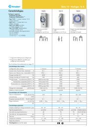
VI-2012, www.findernet.com<br />
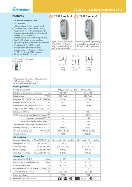
<strong>Features</strong><br />
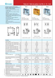
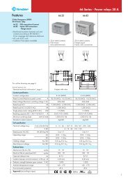
<strong>25</strong> A modular contactor - 2 pole<br />
• 17.5 mm wide<br />
• NO contact gap ≥ 3 mm, double break<br />
• Continuous duty for the coil and contacts<br />
• AC/DC silent coil (with varistor protection)<br />
• Protective separation (reinforced insulation)<br />
between coil and contacts<br />
• Mechanical and LED indicators as standard<br />
• Auto-On-Off selector version available<br />
• AgNi and AgSnO2 contact versions available<br />
• Compliant with EN 61095: 2009<br />
• Auxiliary contact module available,<br />
quick-assembly with the main contactor<br />
(1 NO + 1 NC and 2 NO versions)<br />
• 35 mm rail (EN 60715) mount<br />
<strong>22</strong>.32...1xx0 / <strong>22</strong>.32...4xx0<br />
Screw terminal<br />
* Contact gap ≥ 3 mm for NO contacts only;<br />
NC contacts ≥ 1.5 mm<br />
For outline drawings see page 7<br />
Contact specification<br />
Contact configuration<br />
Rated current/Maximum peak current A<br />
Rated voltage V AC<br />
Rated load AC1 / AC-7a (per pole @ <strong>25</strong>0 V) VA<br />
Rated current AC3 / AC-7b A<br />
Rated load AC15 (per pole @ 230 V) VA<br />
Single-phase motor rating (230 V AC) kW<br />
Rated current AC-7c A<br />
230 V lamps rating: incandescent or halogen W<br />
compact fluorescent (CFL) W<br />
electronic ballast fluorescent tubes W<br />
electromagnetic ballast compens. fluorescent tubes W<br />
Breaking capacity DC1: 30/110/<strong>22</strong>0 V A<br />
Minimum switching load mW (V/mA)<br />
Contact material<br />
Coil specification<br />
Nominal voltage (UN) V DC/AC (50/60 Hz)<br />
Rated power AC/DC VA (50 Hz)/W<br />
Operating range DC/AC (50/60 Hz)<br />
Holding voltage DC/AC (50/60 Hz)<br />
Must drop-out voltage DC/AC (50/60 Hz)<br />
Technical data<br />
Mechanical life AC/DC cycles<br />
Electrical life at rated load AC-7a cycles<br />
Operate/release time ms<br />
Insulation between coil and contacts (1.2/50 μs) kV<br />
Ambient temperature range °C<br />
Protection category<br />
Approvals (according to type)<br />
<strong>22</strong>.32.0.xxx.1xx0 <strong>22</strong>.32.0.xxx.4xx0<br />
• AgNi contacts, specifically<br />
intended for resistive and<br />
slightly inductive loads as<br />
well as for motor loads<br />
<strong>22</strong> <strong>Series</strong> - <strong>Modular</strong> <strong>contactors</strong> <strong>25</strong> A<br />
• AgSnO 2 contacts, specifically<br />
intended for lamp loads and<br />
for high inrush current loads<br />
2 NO 1 NO + 1 NC 2 NC<br />
(x3x0) (x5x0) (x4x0)<br />
2 NO, 3 mm * (or 1 NO + 1 NC or 2 NC)<br />
<strong>25</strong> / 80 <strong>25</strong> / 120<br />
<strong>25</strong>0 / 440 <strong>25</strong>0 / 440<br />
6,<strong>25</strong>0 6,<strong>25</strong>0<br />
10 10<br />
1,800 1,800<br />
1 1<br />
— 10<br />
— 2,000<br />
— 200<br />
— 800<br />
— 500<br />
<strong>25</strong>/5/1 <strong>25</strong>/5/1<br />
1,000 (10 / 10) 1,000 (10 / 10)<br />
AgNi AgSnO2 12 - 24 - 48 - 60 - 120 - 230 12 - 24 - 48 - 60 - 120 - 230<br />
2 /2.2 2 / 2.2<br />
(0.8 …1.1) UN (0.8 …1.1) UN 0.4 UN 0.4 UN 0.1 UN 0.1 UN 2 · 10 6<br />
2 · 10 6<br />
70 · 10 3<br />
30 · 10 3<br />
30 / 20 30 / 20<br />
6 6<br />
–20…+50 –20…+50<br />
IP20 IP20<br />
1
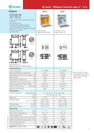
<strong>Features</strong><br />
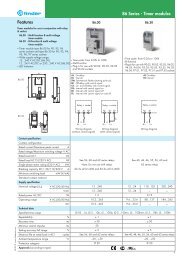
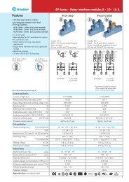
<strong>25</strong> A modular contactor - 4 pole<br />
• 35 mm wide<br />
• NO contact gap ≥ 3 mm, double break<br />
• Continuous duty for the coil and contacts<br />
• AC/DC silent coil (with varistor protection)<br />
• Protective separation (reinforced insulation)<br />
between coil and contacts<br />
• Mechanical and LED indicators as standard<br />
• Auto-On-Off selector version available<br />
• AgNi and AgSnO2 contact versions available<br />
• Compliant with EN 61095: 2009<br />
• Auxiliary contact module available,<br />
quick-assembly with the main contactor<br />
(1 NO + 1 NC and 2 NO versions)<br />
• 35 mm rail (EN 60715) mount<br />
<strong>22</strong>.34...1xx0 / <strong>22</strong>.34...4xx0<br />
Screw terminal<br />
* Contact gap ≥ 3 mm for NO contacts only;<br />
NC contacts ≥ 1.5 mm<br />
For outline drawings see page 7<br />
Contact specification<br />
Contact configuration<br />
Rated current/Maximum peak current A<br />
Rated voltage V AC<br />
Rated load AC1 / AC-7a (per pole @ <strong>25</strong>0 V) VA<br />
Rated current AC3 / AC-7b A<br />
Rated load AC15 (per pole @ 230 V) VA<br />
Three-phase motor rating (400 - 440 V AC) kW<br />
Rated current AC-7c A<br />
230 V lamps rating: incandescent or halogen W<br />
compact fluorescent (CFL) W<br />
electronic ballast fluorescent tubes W<br />
electromagnetic ballast compens. fluorescent tubes W<br />
Breaking capacity DC1: 30/110/<strong>22</strong>0 V A<br />
Minimum switching load mW (V/mA)<br />
Contact material<br />
Coil specification<br />
Nominal voltage (UN) V DC/AC (50/60 Hz)<br />
Rated power AC/DC VA (50 Hz)/W<br />
Operating range DC/AC (50/60 Hz)<br />
Holding voltage DC/AC (50/60 Hz)<br />
Must drop-out voltage DC/AC (50/60 Hz)<br />
Technical data<br />
Mechanical life AC/DC cycles<br />
Electrical life at rated load AC-7a cycles<br />
Operate/release time ms<br />
Insulation between coil and contacts (1.2/50 μs) kV<br />
Ambient temperature range °C<br />
Protection category<br />
Approvals (according to type)<br />
2<br />
<strong>22</strong>.34.0.xxx.1xx0 <strong>22</strong>.34.0.xxx.4xx0<br />
• AgNi contacts, specifically<br />
intended for resistive and<br />
slightly inductive loads as well<br />
as for motor loads<br />
<strong>22</strong> <strong>Series</strong> - <strong>Modular</strong> <strong>contactors</strong> <strong>25</strong> A<br />
• AgSnO 2 contacts, specifically<br />
intended for lamp loads and<br />
for high inrush current loads<br />
4 NO 3 NO + 1 NC 2 NO + 2 NC<br />
(x3x0) (x7x0) (x6x0)<br />
4 NO, 3 mm * (or 3NO + 1NC or 2NO + 2NC)<br />
<strong>25</strong> / 80 <strong>25</strong> / 120<br />
<strong>25</strong>0 / 440 <strong>25</strong>0 / 440<br />
6,<strong>25</strong>0 6,<strong>25</strong>0<br />
10 10<br />
1,800 1,800<br />
4 4<br />
— 10<br />
— 2,000<br />
— 200<br />
— 800<br />
— 500<br />
<strong>25</strong>/5/1 <strong>25</strong>/5/1<br />
1,000 (10 / 10) 1,000 (10 / 10)<br />
AgNi AgSnO2 12 - 24 - 48 - 60 - 120 - 230 12 - 24 - 48 - 60 - 120 - 230<br />
2 / 2.2 2 / 2.2<br />
(0.8 …1.1) UN (0.8 …1.1) UN 0.4 UN 0.4 UN 0.1 UN 0.1 UN 2 · 10 6<br />
2 · 10 6<br />
150 · 10 3<br />
30 · 10 3<br />
18 / 40 18 / 40<br />
6 6<br />
–20…+50 –20…+50<br />
IP20 IP20<br />
VI-2012, www.findernet.com
VI-2012, www.findernet.com<br />
Ordering information<br />
Exemple: <strong>22</strong> series, modular contactor <strong>25</strong> A, 4 NO contacts, coil 230 V AC/DC, AgSnO 2 contacts, Auto-On-Off selector + mechanical indicator + LED.<br />
<strong>Series</strong><br />
Type<br />
3 = <strong>25</strong> A modular contactor range<br />
Number of contacts<br />
2 = 2 pole<br />
4 = 4 pole<br />
Coil version<br />
0 = AC(50/60 Hz)/DC<br />
Coil rated voltage<br />
See coil specifications<br />
<strong>22</strong> <strong>Series</strong> - <strong>Modular</strong> <strong>contactors</strong> <strong>25</strong> A<br />
2 2 . 3 4 . 0 . 2 3 0 . 4 3 4 0<br />
Selecting features and options: only combinations in the same row are possible.<br />
Preferred selections for best availability are shown in bold.<br />
Type Coil version A B C D<br />
<strong>22</strong>.32 AC/DC 1 - 4 3 - 4 - 5 2 - 4 0<br />
<strong>22</strong>.34 AC/DC 1 - 4 3 - 6 - 7 2 - 4 0<br />
Auto-On-Off selector + mechanical indicator + LED (xx40 option)<br />
1<br />
2<br />
3<br />
1<br />
2<br />
3<br />
D: Special versions<br />
0 = Standard<br />
C: Options<br />
2 = mechanical indicator + LED<br />
4 = Auto-On-Off selector +<br />
mechanical indicator + LED<br />
B: Contact circuit<br />
3 = All NO contacts<br />
4 = All NC contacts (<strong>22</strong>.32 only)<br />
5 = 1 NO + 1 NC<br />
6 = 2 NO + 2 NC<br />
7 = 3 NO + 1 NC<br />
A: Contact material<br />
1 = AgNi<br />
4 = AgSnO2 Selector<br />
The three-position manual selector has the following functions:<br />
ON position - the contacts are latched in the operated state<br />
(NO contacts - closed and NC contacts - open), the mechanical<br />
indicator is visible in its window, the LED is not illuminated.<br />
LED<br />
A B C D<br />
AUTO position - the state of contacts, mechanical indicator<br />
and LED follow the coil supply voltage.<br />
OFF position - even if terminals A1 - A2 are supplied with<br />
rated voltage, the coil is not energized, and so the contacts<br />
remain in the non-operated state, the mechanical indicator is<br />
not visible and the LED is not illuminated.<br />
Mechanical indicator<br />
3
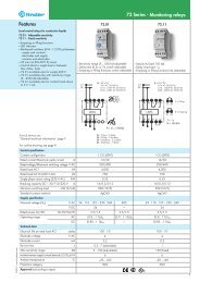
Technical data<br />
Insulation<br />
<strong>22</strong> <strong>Series</strong> - <strong>Modular</strong> <strong>contactors</strong> <strong>25</strong> A<br />
Rated insulation voltage V AC <strong>25</strong>0 440<br />
Pollution degree 3 * 2<br />
Insulation between coil and contact set<br />
Type of insulation Reinforced<br />
Overvoltage category III<br />
Rated impulse voltage kV (1.2/50 μs) 6<br />
Dielectric strength V AC 4,000<br />
Insulation between adjacent contacts<br />
Type of insulation Basic<br />
Overvoltage category III<br />
Rated impulse voltage kV (1.2/50 μs) 4<br />
Dielectric strength V AC 2,500<br />
Insulation between open contacts NO contact NC contact<br />
Contact gap mm 3 1.5<br />
Overvoltage category III II<br />
Rated impulse voltage kV (1.2/50 μs) 4 2.5<br />
Dielectric strength V AC/kV (1.2/50 μs) 2,500/4 2,000/3<br />
* Only for versions without Auto-On-Off selector. For versions with Auto-On-Off selector pollution degree 2 applies.<br />
Conducted disturbance immunity Reference standard<br />
Fast transients (burst 5/50 ns, 5 kHz) at coil terminals EN 61000-4-4 Level 4 (4 kV)<br />
Voltage pulses (surge 1.2/50 μs) at supply terminals (differential mode)<br />
Short circuit protection<br />
EN 61000-4-5 Level 4 (4 kV)<br />
Rated conditional short circuit current kA 3<br />
Back-up fuse A 32 (gL/gG type)<br />
Terminals Solid and stranded cable<br />
Max. wire size – contact terminals mm 2 1 x 6 / 2 x 4<br />
AWG 1 x 10 / 2 x 12<br />
Max. wire size – coil terminals mm 2 1 x 4 / 2 x 2.5<br />
AWG 1 x 12 / 2 x 14<br />
Min. wire size – contact and coil terminals mm 2 1 x 0.2<br />
AWG 1 x 24<br />
Screw torque Nm 0.8<br />
Wire strip length mm 9<br />
Power lost to the environment <strong>22</strong>.32 <strong>22</strong>.34<br />
without contact current W 2 2<br />
with rated current W 4.8 6.3<br />
NOTE - It is suggested an air gap of 9 mm between adjacent relays for installations and working conditions close to the limit (that is, ambient<br />
temperature > 40 °C, coil operated for a prolonged period of time, all contacts loaded with current > 20 A).<br />
4<br />
VI-2012, www.findernet.com
VI-2012, www.findernet.com<br />
Contact specification<br />
H <strong>22</strong> - Maximum DC1 breaking capacity<br />
DC breaking current (A)<br />
Coil specifications<br />
AC/DC version data (type <strong>22</strong>.32)<br />
Nominal Coil Operating range Rated coil<br />
voltage code consumption<br />
U N U min U max I N at U N (AC)<br />
V V V mA<br />
12 0.012 9.6 13.2 165<br />
24 0.024 19.2 26.4 83<br />
48 0.048 38.4 52.8 42<br />
60 0.060 48 66 33<br />
120 0.120 88 138 16.5<br />
(110...1<strong>25</strong>)<br />
230<br />
(230...240 AC) 0.230<br />
(<strong>22</strong>0 DC)<br />
DC voltage (V)<br />
184 (AC) 264 (AC)<br />
176 (DC) 242 (DC)<br />
R <strong>22</strong> - Coil operating range v ambient temperature<br />
8.7<br />
1 - Max. permitted coil voltage.<br />
2 - Min. pick-up voltage with coil at ambient temperature.<br />
<strong>22</strong> <strong>Series</strong> - <strong>Modular</strong> <strong>contactors</strong> <strong>25</strong> A<br />
Ratings and utilization categories according to EN 61095: 2009<br />
Utilization Typical Load Rated Rated Rated electrical life (cycles)<br />
category applications characteristics current operational 2-pole 2-pole 4-pole 4-pole<br />
( A ) voltage AgNi contacts AgSnO2 contacts AgNi contacts AgSnO2 contacts<br />
( V )<br />
across between<br />
the pole phases<br />
(<strong>22</strong>.32...1xx0) (<strong>22</strong>.32...4xx0) (<strong>22</strong>.34...1xx0) (<strong>22</strong>.34...4xx0)<br />
AC-7a<br />
Slightly<br />
70 · 10<br />
cos ϕ = 0.8 <strong>25</strong> <strong>25</strong>0 440<br />
3 (NO)<br />
30 · 10 3<br />
150 · 10 3 (NO)<br />
inductive loads 30 · 10 3 (NC) 100 · 10 3 (NC)<br />
AC-7b Motor loads<br />
Compensated<br />
AC-7c electric discharge<br />
lamps<br />
cos ϕ = 0.45<br />
Imaking = 6 Ibreaking cos ϕ = 0.9<br />
C = 10 μF/A<br />
10 <strong>25</strong>0 440 30 · 10 3<br />
When switching a resistive load (DC1) having voltage and current<br />
values under the curve, an electrical life of ≥ 100·10 3 can be expected.<br />
In the case of DC13 loads, the connection of a diode in parallel with<br />
the load will permit a similar electrical life as for a DC1 load.<br />
Note: the release time for the load will be increased.<br />
AC/DC version data (type <strong>22</strong>.34)<br />
Nominal Coil Operating range Rated coil<br />
voltage code consumption<br />
U N U min U max I N at U N (AC)<br />
V V V mA<br />
12 0.012 9.6 13.2 165<br />
24 0.024 19.2 26.4 83<br />
48 0.048 38.4 52.8 42<br />
60 0.060 48 66 33<br />
120 0.120 88 138 16.5<br />
(110...1<strong>25</strong>)<br />
230<br />
(230...240 AC) 0.230<br />
(<strong>22</strong>0 DC)<br />
30 · 10 3<br />
10 230 400 — 30 · 10 3<br />
184 (AC) 264 (AC)<br />
176 (DC) 242 (DC)<br />
30 · 10 3<br />
8.7<br />
30 · 10 3<br />
30 · 10 3<br />
— 30 · 10 3<br />
5
Wiring diagrams<br />
6<br />
Line and neutral switched<br />
Type <strong>22</strong>.34<br />
Type <strong>22</strong>.32<br />
<strong>22</strong> <strong>Series</strong> - <strong>Modular</strong> <strong>contactors</strong> <strong>25</strong> A<br />
Line only switched<br />
Type <strong>22</strong>.34<br />
VI-2012, www.findernet.com
VI-2012, www.findernet.com<br />
Outline drawings<br />
Type <strong>22</strong>.32<br />
Screw terminal<br />
Type <strong>22</strong>.34<br />
Screw terminal<br />
Type 0<strong>22</strong>.33 / 0<strong>22</strong>.35<br />
Screw terminal<br />
<strong>22</strong> <strong>Series</strong> - <strong>Modular</strong> <strong>contactors</strong> <strong>25</strong> A<br />
Type <strong>22</strong>.32 + 0<strong>22</strong>.33 / 0<strong>22</strong>.35<br />
Screw terminal<br />
Type <strong>22</strong>.34 + 0<strong>22</strong>.33 / 0<strong>22</strong>.35<br />
Screw terminal<br />
7
Auxiliary module 0<strong>22</strong>.33 / 0<strong>22</strong>.35<br />
8<br />
<strong>22</strong>.32 + 0<strong>22</strong>.33 / 0<strong>22</strong>.35 <strong>22</strong>.34 + 0<strong>22</strong>.33 / 0<strong>22</strong>.35<br />
Contact specification<br />
Contact configuration 2 NO 1 NO + 1 NC<br />
Conventional free air thermal current I th A 6 6<br />
Rated current AC15 (230 V) VA 700 700<br />
Electrical life at rated load cycles 30 x 10 3<br />
<strong>22</strong> <strong>Series</strong> - <strong>Modular</strong> <strong>contactors</strong> <strong>25</strong> A<br />
Contact material<br />
Short circuit protection<br />
AgNi AgNi<br />
Rated conditional short circuit current kA 1<br />
Back-up fuse A 6 (gL/gG type)<br />
Terminals Solid and stranded cable<br />
Max. wire size mm 2<br />
1 x 4 / 2 x 2.5<br />
AWG 1 x 12 / 2 x 14<br />
Min. wire size mm 2<br />
1 x 0.2<br />
AWG 1 x 24<br />
Screw torque Nm 0.8<br />
Wire strip length<br />
Power lost to the environment<br />
mm 9<br />
without contact current W —<br />
with rated current<br />
Approvals (according to type)<br />
W 0.5<br />
NOTE: it is not possible to assembly the auxiliary module on <strong>22</strong>.32.0.xxx.x4x0 (2 NC versions).<br />
0<strong>22</strong>.33 0<strong>22</strong>.35<br />
30 x 10 3<br />
VI-2012, www.findernet.com
VI-2012, www.findernet.com<br />
Accessories<br />
011.01<br />
060.72<br />
019.01<br />
020.03<br />
0<strong>22</strong>.18<br />
0<strong>22</strong>.26<br />
020.01<br />
P A T E N T<br />
P A T E N T<br />
E U R O P E A N E U R O P E A N<br />
E U R O P E A N E U R O P E A N<br />
<strong>22</strong> <strong>Series</strong> - <strong>Modular</strong> <strong>contactors</strong> <strong>25</strong> A<br />
Adaptor for panel mounting (for <strong>22</strong>.32 type), plastic, 17.5 mm wide 020.01<br />
Adaptor for panel mounting (for <strong>22</strong>.34 type), plastic, 35 mm wide 011.01<br />
Sheet of marker tags, plastic, 72 tags, 6x12 mm 060.72<br />
Identification tag, plastic, 1 tag, 17x<strong>25</strong>.5 mm 019.01<br />
Separator for rail mounting, plastic, 3 mm wide 020.03<br />
8-way jumper link for types <strong>22</strong>.32, 17.5 mm wide 0<strong>22</strong>.18 (blue)<br />
Rated values 10 A - <strong>25</strong>0 V<br />
6-way jumper link for types <strong>22</strong>.34, 35 mm wide 0<strong>22</strong>.26 (blue)<br />
Rated values 10 A - <strong>25</strong>0 V<br />
9