Features 66 Series - Power relays 30 A - Finder
Features 66 Series - Power relays 30 A - Finder
Features 66 Series - Power relays 30 A - Finder

You also want an ePaper? Increase the reach of your titles
YUMPU automatically turns print PDFs into web optimized ePapers that Google loves.
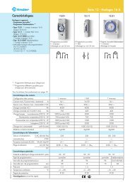
VII-2012, www.findernet.com<br />
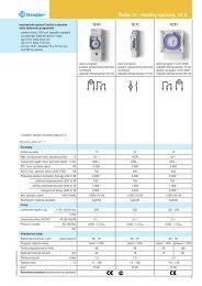
<strong>Features</strong><br />
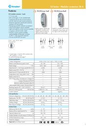
2 Pole Changeover (DPDT)<br />
<strong>30</strong> A <strong>Power</strong> relay<br />
<strong>66</strong>.22 PCB connections & mount<br />
<strong>66</strong>.82 Faston 250 connections<br />
- Flange mount<br />
• Reinforced insulation between coil and<br />
contacts according to EN 60335-1;<br />
8 mm creepage and clearance distances<br />
• AC coils & DC coils<br />
• Cadmium Free option available • <strong>30</strong> A rated contacts<br />
• PCB mount -<br />
bifurcated terminals<br />
For outline drawing see page 6<br />
FOR UL RATINGS SEE:<br />
“General technical information” page V<br />
Contact specification<br />
Contact configuration<br />
Rated current/Maximum peak current A<br />
Rated voltage/Maximum switching voltage V AC<br />
Rated load AC1 VA<br />
Rated load AC15 (2<strong>30</strong> V AC) VA<br />
Single phase motor rating (2<strong>30</strong> V AC) kW<br />
Breaking capacity DC1: <strong>30</strong>/110/220 V A<br />
Minimum switching load<br />
Standard contact material<br />
Coil specification<br />
mW (V/mA)<br />
Nominal voltage (UN) V AC (50/60 Hz)<br />
V DC<br />
Rated power AC/DC VA (50 Hz)/W<br />
Operating range AC<br />
DC<br />
Holding voltage AC/DC<br />
Must drop-out voltage<br />
Technical data<br />
AC/DC<br />
Mechanical life AC/DC cycles<br />
Electrical life at rated load AC1 cycles<br />
Operate/release time ms<br />
Insulation between coil and contacts (1.2/50 μs) kV<br />
Dielectric strength between open contacts V AC<br />
Ambient temperature range<br />
Environmental protection<br />
Approvals (according to type)<br />
°C<br />
<strong>66</strong>.22 <strong>66</strong>.82<br />
Copper side view<br />
• <strong>30</strong> A rated contacts<br />
• Flange mount<br />
• Faston 250 connections<br />
2 CO (DPDT) 2 CO (DPDT)<br />
<strong>30</strong>/50 (NO) - 10/20 (NC) <strong>30</strong>/50 (NO) - 10/20 (NC)<br />
250/440 250/440<br />
7,500 (NO) - 2,500 (NC) 7,500 (NO) - 2,500 (NC)<br />
1,200 (NO) 1,200 (NO)<br />
1.5 (NO) 1.5 (NO)<br />
25/0.7/0.3 (NO) 25/0.7/0.3 (NO)<br />
1,000 (10/10) 1,000 (10/10)<br />
AgCdO AgCdO<br />
6 - 12 - 24 - 110/115 - 120/125 - 2<strong>30</strong> - 240<br />
6 - 12 - 24 - 110 - 125<br />
3.6/1.7 3.6/1.7<br />
(0.8…1.1)UN (0.8…1.1)UN (0.8…1.1)UN (0.8…1.1)UN 0.8 UN/0.5 UN 0.8 UN/0.5 UN 0.2 UN/0.1 UN 0.2 UN/0.1 UN 10 · 10 6<br />
10 · 10 6<br />
100 · 10 3<br />
100 · 10 3<br />
8/15 8/15<br />
6 (8 mm) 6 (8 mm)<br />
1,500 1,500<br />
–40…+70 –40…+70<br />
RT II RT II<br />
<strong>66</strong> <strong>Series</strong> - <strong>Power</strong> <strong>relays</strong> <strong>30</strong> A<br />
1
<strong>Features</strong><br />
Contact specification<br />
Contact configuration<br />
Rated current/Maximum peak current A<br />
Rated voltage/Maximum switching voltage V AC<br />
Rated load AC1 VA<br />
Rated load AC15 (2<strong>30</strong> V AC) VA<br />
Single phase motor rating (2<strong>30</strong> V AC) kW<br />
Breaking capacity DC1: <strong>30</strong>/110/220 V A<br />
Minimum switching load<br />
Standard contact material<br />
Coil specification<br />
mW (V/mA)<br />
Nominal voltage (UN) V AC (50/60 Hz)<br />
V DC<br />
Rated power AC/DC VA (50 Hz)/W<br />
Operating range AC<br />
DC<br />
Holding voltage AC/DC<br />
Must drop-out voltage<br />
Technical data<br />
AC/DC<br />
Mechanical life AC/DC cycles<br />
Electrical life at rated load AC1 cycles<br />
Operate/release time ms<br />
Insulation between coil and contacts (1.2/50 μs) kV<br />
Dielectric strength between open contacts V AC<br />
Ambient temperature range<br />
Environmental protection<br />
Approvals (according to type)<br />
°C<br />
2<br />
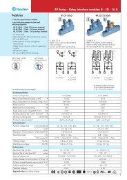
<strong>66</strong>.22-x<strong>30</strong>0 <strong>66</strong>.82-x<strong>30</strong>0<br />
2 Pole NO (DPST-NO)<br />
<strong>30</strong> A <strong>Power</strong> relay<br />
<strong>66</strong>.22-x<strong>30</strong>0 PCB mount<br />
<strong>66</strong>.82-x<strong>30</strong>0 Faston 250 connections<br />
- Flange mount<br />
• Reinforced insulation between coil and<br />
contacts according to EN 60335-1;<br />
8 mm creepage and clearance distances<br />
• AC coils & DC coils<br />
• Cadmium Free option available • <strong>30</strong> A rated contacts<br />
• <strong>30</strong> A rated contacts<br />
• PCB mount -<br />
• Flange mount<br />
bifurcated terminals<br />
• Faston 250 connections<br />
For outline drawing see page 6<br />
FOR UL RATINGS SEE:<br />
“General technical information” page V<br />
Copper side view<br />
2 NO (DPST-NO) 2 NO (DPST-NO)<br />
<strong>30</strong>/50 <strong>30</strong>/50<br />
250/440 250/440<br />
7,500 7,500<br />
1,200 1,200<br />
1.5 1.5<br />
25/0.7/0.3 25/0.7/0.3<br />
1,000 (10/10) 1,000 (10/10)<br />
AgCdO AgCdO<br />
6 - 12 - 24 - 110/115 - 120/125 - 2<strong>30</strong> - 240<br />
6 - 12 - 24 - 110 -125<br />
3.6/1.7 3.6/1.7<br />
(0.8…1.1)UN (0.8…1.1)UN (0.8…1.1)UN (0.8…1.1)UN 0.8 UN/0.5 UN 0.8 UN/0.5 UN 0.2 UN/0.1 UN 0.2 UN/0.1 UN 10 · 10 6<br />
10 · 10 6<br />
100 · 10 3<br />
100 · 10 3<br />
8/10 8/10<br />
6 (8 mm) 6 (8 mm)<br />
1,500 1,500<br />
–40…+70 –40…+70<br />
RT II RT II<br />
<strong>66</strong> <strong>Series</strong> - <strong>Power</strong> <strong>relays</strong> <strong>30</strong> A<br />
VII-2012, www.findernet.com
VII-2012, www.findernet.com<br />
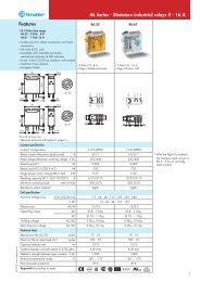
<strong>Features</strong><br />
2 Pole NO (DPST-NO), ≥1.5mm contact gap<br />
<strong>30</strong> A <strong>Power</strong> relay<br />
<strong>66</strong>.22-x600 PCB mount<br />
<strong>66</strong>.22-x600S PCB mount - 5 mm gap<br />
between PCB and relay base<br />
<strong>66</strong>.82-x600 Faston 250 connections<br />
- Flange mount<br />
• ≥1.5 mm contact gap (according to VDE 0126-1-1<br />
for solar inverter applications)<br />
• Reinforced insulation between coil and<br />
contacts according to EN 60335-1;<br />
8 mm creepage and clearance distances<br />
• Wash tight version (RT III) available<br />
• DC coils<br />
• Cadmium Free option available<br />
For outline drawing see page 6<br />
FOR UL RATINGS SEE:<br />
“General technical information” page V<br />
Contact specification<br />
Contact configuration<br />
Rated current/Maximum peak current A<br />
Rated voltage/Maximum switching voltage V AC<br />
Rated load AC1 VA<br />
Rated load AC15 (2<strong>30</strong> V AC) VA<br />
Single phase motor rating (2<strong>30</strong> V AC) kW<br />
Breaking capacity DC1: <strong>30</strong>/110/220 V A<br />
Minimum switching load<br />
Standard contact material<br />
Coil specification<br />
mW (V/mA)<br />
Nominal voltage (UN) V AC (50/60 Hz)<br />
V DC<br />
Rated power AC/DC VA (50 Hz)/W<br />
Operating range AC<br />
DC<br />
Holding voltage AC/DC<br />
Must drop-out voltage<br />
Technical data<br />
AC/DC<br />
Mechanical life cycles<br />
Electrical life at rated load AC1 cycles<br />
Operate/release time ms<br />
Insulation between coil and contacts (1.2/50 μs) kV<br />
Dielectric strength between open contacts V AC<br />
Ambient temperature range<br />
Environmental protection<br />
Approvals (according to type)<br />
°C<br />
<strong>66</strong>.22-x600 <strong>66</strong>.22-x600S <strong>66</strong>.82-x600<br />
• PCB mount -<br />
bifurcated terminals<br />
Copper side view Copper side view<br />
<strong>66</strong> <strong>Series</strong> - <strong>Power</strong> <strong>relays</strong> <strong>30</strong> A<br />
• PCB mount -<br />
bifurcated terminals<br />
• 5 mm gap between PCB and<br />
relay base<br />
• Flange mount<br />
• Faston 250 connections<br />
2 NO (DPST-NO) 2 NO (DPST-NO) 2 NO (DPST-NO)<br />
<strong>30</strong>/50 <strong>30</strong>/50 <strong>30</strong>/50<br />
250/440 250/440 250/440<br />
7,500 7,500 7,500<br />
1,200 1,200 1,200<br />
1.5 1.5 1.5<br />
<strong>30</strong>/1.2/0.5 <strong>30</strong>/1.2/0.5 <strong>30</strong>/1.2/0.5<br />
1,000 (10/10) 1,000 (10/10) 1,000 (10/10)<br />
AgCdO AgCdO AgCdO<br />
—/1.7<br />
—<br />
6 - 12 - 24 - 110 -125<br />
—/1.7 —/1.7<br />
— — —<br />
(0.8…1.1)UN (0.7…1.1)UN (0.8…1.1)UN —/0.5 UN —/0.5 UN —/0.5 UN —/0.1 UN —/0.1 UN —/0.1 UN 10 · 10 6<br />
10 · 10 6<br />
10 · 10 6<br />
100 · 10 3<br />
100 · 10 3<br />
100 · 10 3<br />
15/4 15/4 15/4<br />
6 (8 mm) 6 (8 mm) 6 (8 mm)<br />
2,500 2,500 2,500<br />
–40…+70 –40…+70 –40…+70<br />
RT II RT II RT II<br />
3
Ordering information<br />
4<br />
Example: <strong>66</strong> series relay, Faston 250 (6.3x0.8 mm) with top flange mount, 2 CO (DPDT) <strong>30</strong> A contacts, 24 V DC coil.<br />
6 6<br />
<strong>Series</strong><br />
Type<br />
2 = PCB<br />
8 = Faston 250 (6.3x0.8 mm)<br />
with top flange mount<br />
No. of poles<br />
2 = 2 pole, <strong>30</strong> A<br />
Coil version<br />
8 = AC (50/60 Hz)<br />
9 = DC<br />
Coil voltage<br />
See coil specifications<br />
. 8 2 . 9 . 0 2 4 . 0 0<br />
A: Contact material<br />
0 = Standard AgCdO<br />
1 = AgNi<br />
B: Contact circuit<br />
0 = CO (nPDT)<br />
3 = NO (nPST)<br />
6 = NO (nPST), ≥1.5 mm<br />
contact gap<br />
Selecting features and options: only combinations in the same row are possible.<br />
Preferred selections for best availability are shown in bold.<br />
Type Coil version A B C D<br />
<strong>66</strong>.22 AC-DC 0 - 1 0 - 3 0 0 - 1<br />
Technical data<br />
DC 0 - 1 6 0 0 - 1<br />
<strong>66</strong>.22....S DC 0 - 1 6 0 0 - 1<br />
<strong>66</strong>.82 AC-DC 0 - 1 0 - 3 0 0 - 1<br />
DC 0 - 1 6 0 0 - 1<br />
A B C D<br />
<strong>66</strong> <strong>Series</strong> - <strong>Power</strong> <strong>relays</strong> <strong>30</strong> A<br />
0 0<br />
S = PCB version with 5 mm gap<br />
between PCB and relay base<br />
(only <strong>66</strong>.22)<br />
D: Special versions<br />
0 = Standard<br />
1 = Wash tight (RT III)<br />
C: Options<br />
0 = None<br />
Insulation according to EN 61810-1<br />
Nominal voltage of supply system V AC 2<strong>30</strong>/400<br />
Rated insulation voltage V AC 400<br />
Pollution degree<br />
Insulation between coil and contact set<br />
3<br />
Type of insulation Reinforced (8 mm)<br />
Overvoltage category III<br />
Rated impulse voltage kV (1.2/50 μs) 6<br />
Dielectric strength<br />
Insulation between adjacent contacts<br />
V AC 4,000<br />
Type of insulation Basic<br />
Overvoltage category III<br />
Rated impulse voltage kV (1.2/50 μs) 4<br />
Dielectric strength V AC 2,500<br />
Insulation between open contacts 2 CO 2 NO, ≥1.5mm (x600 version)<br />
Type of disconnection Micro-disconnection Full-disconnection *<br />
Overvoltage category — II<br />
Rated impulse voltage kV (1.2/50 μs) — 2.5<br />
Dielectric strength<br />
Conducted disturbance immunity<br />
V AC/kV (1.2/50 μs) 1,500/2 2,500/3<br />
Burst (5...50)ns, 5 kHz, on A1 - A2 EN 61000-4-4 level 4 (4 kV)<br />
Surge (1.2/50 μs) on A1 - A2 (differential mode)<br />
Other data<br />
EN 61000-4-5 level 4 (4 kV)<br />
Bounce time: NO/NC ms 7/10<br />
Vibration resistance (10...150)Hz: NO/NC g 20/19<br />
Shock resistance g 20<br />
<strong>Power</strong> lost to the environment without contact current W 2.3<br />
with rated current W 5<br />
Recommended distance between <strong>relays</strong> mounted on PCB mm ≥ 10<br />
* Only in applications where over voltage category II is permitted. In applications of over voltage category III: Micro-disconnection.<br />
VII-2012, www.findernet.com
VII-2012, www.findernet.com<br />
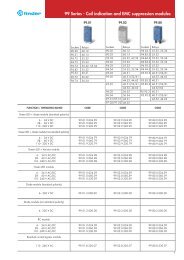
Contact specification<br />
F <strong>66</strong> - Electrical life (AC) v contact current<br />
250 V (normally open contact)<br />
Cycles<br />
H <strong>66</strong> - Maximum DC breaking capacity<br />
DC breaking current (A)<br />
Coil specifications<br />
DC coil data<br />
Resistive load - 250 V AC cosϕ = 1<br />
Inductive load - 250 V AC cosϕ = 0.4<br />
DC voltage (V)<br />
Nominal Coil Operating range Resistance Rated coil<br />
voltage code consumption<br />
U N U min U max R I at U N<br />
V V V Ω mA<br />
6 9.006 4.8 6.6 21 283<br />
12 9.012 9.6 13.2 85 141<br />
24 9.024 19.2 26.4 340 70.5<br />
110 9.110 88 121 7,000 15.7<br />
125 9.125 100 138 9,200 13.6<br />
AC coil data<br />
<strong>66</strong> <strong>Series</strong> - <strong>Power</strong> relay <strong>30</strong> A<br />
F <strong>66</strong> - Electrical life (AC) v contact current<br />
440 V (normally open contact)<br />
• When switching a resistive load (DC1) having voltage and current values under the curve, an electrical life of ≥ 100·10 3 can be expected.<br />
• In the case of DC13 loads, the connection of a diode in parallel with the load will permit a similar electrical life as for a DC1 load.<br />
Note: the release time for the load will be increased.<br />
R <strong>66</strong> - DC coil operating range v ambient temperature<br />
1 - Max. permitted coil voltage.<br />
2 - Min. pick-up voltage with coil at ambient temperature.<br />
3 - Min. pick-up voltage with coil at ambient temperature (<strong>66</strong>.22-x600S).<br />
Cycles<br />
H <strong>66</strong> - Maximum DC breaking capacity, x600 versions<br />
(>1.5mm contact gap)<br />
DC breaking current (A)<br />
Resistive load - 440 V AC cosϕ = 1<br />
Inductive load - 440 V AC cosϕ = 0.4<br />
DC voltage (V)<br />
Nominal Coil Operating range Resistance Rated coil<br />
voltage code consumption<br />
U N U min U max R I at U N (50Hz)<br />
V V V Ω mA<br />
6 8.006 4.8 6.6 3 600<br />
12 8.012 9.6 13.2 11 <strong>30</strong>0<br />
24 8.024 19.2 26.4 50 150<br />
110/115 8.110 88 126 9<strong>30</strong> 32.6<br />
120/125 8.120 96 137 1,050 <strong>30</strong><br />
2<strong>30</strong> 8.2<strong>30</strong> 184 253 4,000 15.7<br />
240 8.240 192 264 5,500 15<br />
R <strong>66</strong> - AC coil operating range v ambient temperature<br />
1 - Max. permitted coil voltage.<br />
2 - Min. pick-up voltage with coil at ambient temperature.<br />
5
Outline drawings<br />
Type <strong>66</strong>.22<br />
Type <strong>66</strong>.22-0<strong>30</strong>0<br />
Accessories<br />
0<strong>66</strong>.07<br />
0<strong>66</strong>.07 with relay<br />
6<br />
Type <strong>66</strong>.82<br />
Type <strong>66</strong>.82-0<strong>30</strong>0<br />
Type <strong>66</strong>.22-0600 Type <strong>66</strong>.82-0600<br />
Type <strong>66</strong>.22-0600S<br />
<strong>66</strong> <strong>Series</strong> - <strong>Power</strong> relay <strong>30</strong> A<br />
Top 35 mm rail (EN 60715) mount for types <strong>66</strong>.82.xxxx.0x00 0<strong>66</strong>.07<br />
0<strong>66</strong>.07 0<strong>66</strong>.07 with relay<br />
VII-2012, www.findernet.com