

Atmel AVR1622: TWI Boot Loader for XMEGA - Atmel Corporation
Atmel AVR1622: TWI Boot Loader for XMEGA - Atmel Corporation
Atmel AVR1622: TWI Boot Loader for XMEGA - Atmel Corporation

Create successful ePaper yourself
Turn your PDF publications into a flip-book with our unique Google optimized e-Paper software.
<strong>Atmel</strong> <strong>AVR1622</strong>: <strong>TWI</strong> <strong>Boot</strong> <strong>Loader</strong> <strong>for</strong> <strong>XMEGA</strong><br />
Features<br />
• <strong>Atmel</strong> ® AVR ® <strong>XMEGA</strong> ® boot loader<br />
- Uses <strong>TWI</strong> interface<br />
• C-code <strong>for</strong> self programming<br />
• Designed to work with Windows ® utility <strong>TWI</strong>GEN (AVR1624)<br />
• Read and write flash<br />
1 Introduction<br />
As many electronic designs evolve rapidly there is a growing need <strong>for</strong> being able to<br />
update products, which have already been shipped or sold. Microcontrollers that<br />
support boot loader facilitates updating the application flash section without the need<br />
of an external programmer, are of great use in situations where the application has to<br />
be updated on the field. The boot loader may use various interfaces like SPI, UART,<br />
<strong>TWI</strong>, Ethernet etc.<br />
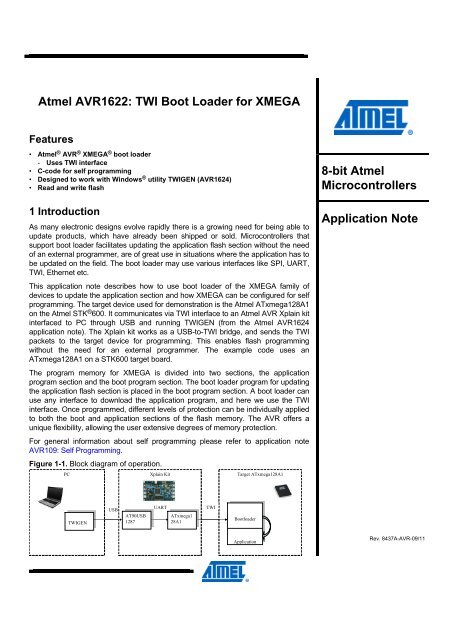
This application note describes how to use boot loader of the <strong>XMEGA</strong> family of<br />
devices to update the application section and how <strong>XMEGA</strong> can be configured <strong>for</strong> self<br />
programming. The target device used <strong>for</strong> demonstration is the <strong>Atmel</strong> ATxmega128A1<br />
on the <strong>Atmel</strong> STK ® 600. It communicates via <strong>TWI</strong> interface to an <strong>Atmel</strong> AVR Xplain kit<br />
interfaced to PC through USB and running <strong>TWI</strong>GEN (from the <strong>Atmel</strong> AVR1624<br />
application note). The Xplain kit works as a USB-to-<strong>TWI</strong> bridge, and sends the <strong>TWI</strong><br />
packets to the target device <strong>for</strong> programming. This enables flash programming<br />
without the need <strong>for</strong> an external programmer. The example code uses an<br />
ATxmega128A1 on a STK600 target board.<br />
The program memory <strong>for</strong> <strong>XMEGA</strong> is divided into two sections, the application<br />
program section and the boot program section. The boot loader program <strong>for</strong> updating<br />
the application flash section is placed in the boot program section. A boot loader can<br />
use any interface to download the application program, and here we use the <strong>TWI</strong><br />
interface. Once programmed, different levels of protection can be individually applied<br />
to both the boot and application sections of the flash memory. The AVR offers a<br />
unique flexibility, allowing the user extensive degrees of memory protection.<br />
For general in<strong>for</strong>mation about self programming please refer to application note<br />
AVR109: Self Programming.<br />
Figure 1-1. Block diagram of operation.<br />
PC<br />
<strong>TWI</strong>GEN<br />
<strong>TWI</strong>GEN<br />
USB<br />
Xplain Kit<br />
UART<br />
AT90USB<br />
AT90USB<br />
ATxmega1<br />
ATxmega1<br />
1287<br />
1287<br />
28A1<br />
28A1<br />
<strong>TWI</strong><br />
Target ATxmega128A1<br />
<strong>Boot</strong>loader<br />
<strong>Boot</strong>loader<br />
Application<br />
Application<br />
8-bit <strong>Atmel</strong><br />
Microcontrollers<br />
Application Note<br />
Rev. 8437A-AVR-09/11
2 Getting up and running<br />
2.1 Hardware setup<br />
2.2 Setting Xplain kit as bridge<br />
2 <strong>Atmel</strong> <strong>AVR1622</strong><br />
This chapter walks you through the basic steps <strong>for</strong> getting up and running, by setting<br />
up the hardware. The necessary setup and requirements are described along with<br />
relevant in<strong>for</strong>mation.<br />
This section explains the procedure to be followed <strong>for</strong> setting up the hardware <strong>for</strong><br />
programming using boot loader through <strong>TWI</strong> interface.<br />
The boot loader program given with this application note uses <strong>TWI</strong>GEN as the user<br />
interface on the PC. It implements read and write routines <strong>for</strong> reading/updating the<br />
flash section.<br />
Since <strong>TWI</strong> cannot be used <strong>for</strong> direct communication with a PC, an <strong>Atmel</strong> AVR Xplain<br />
kit is used in between <strong>for</strong> bridge function. The <strong>Atmel</strong> AT90USB1287 microcontroller in<br />
the Xplain kit is programmed with an USB-to-UART (CDC) application and the <strong>Atmel</strong><br />
ATxmega128A1 in the Xplain kit is programmed with an USART-to-<strong>TWI</strong> bridge<br />
application. The bridge functionality along with the <strong>TWI</strong>GEN source code is available<br />
in the <strong>Atmel</strong> application note AVR1624.<br />
Connect PD0 and PD1 (SDA and SCL of <strong>TWI</strong> interface on PORTD) of the<br />
ATxmega128A1 on the Xplain kit to PC0 and PC1 (SDA and SCL of <strong>TWI</strong> interface on<br />
PORTC) of the ATxmega128A1 on the <strong>Atmel</strong> STK600. Connect GND from the Xplain<br />
kit to GND on the <strong>Atmel</strong> STK600. Since internal pull-ups are enabled in the<br />
application on the ATxmega128A1 of the Xplain kit, no external pull-ups are needed<br />
here.<br />
On the STK600, connect PB0 to SW0 to enable the device to enter programming<br />
mode when switch is being pressed.<br />
Please refer to the STK600 user guide, available in the <strong>Atmel</strong> AVR Studio ® help, to<br />
mount the device with correct routing and socket cards combination and connecting<br />
port pins to switch.<br />
This section explains the procedure to make the Xplain kit act as a USB-to-UART<br />
bridge between the target device ATxmega128A1 in the STK600 and PC.<br />
‘Xplain_USB.a90’, ‘at90usbxxx_cdc.inf’ and ‘XplainSerialToI2C<strong>Boot</strong><strong>Loader</strong><br />
Bridge.hex’ are available with the <strong>Atmel</strong> AVR1624.<br />
1. Connect the <strong>Atmel</strong> AVR JTAGICE mkII to the JTAG USB on the Xplain kit.<br />
2. Power on the JTAGICE mkII and the Xplain Kit.<br />
3. Start the AVR Studio.<br />
4. Open programming dialog and connect to <strong>Atmel</strong> AT90USB1287 through the<br />
JTAG interface (make sure that both JTAGICE mkII and Xplain kit are powered).<br />
5. Select the program tab. Under ‘Flash’, <strong>for</strong> the input HEX file, browse to the folder<br />
containing the Xplain_USB.a90 file and program the same file.<br />
6. Close the programming dialog.<br />
7. A popup occurs prompting to install the software. Select ‘Install from a list or<br />
specific location (Advanced)’ and browse to the ‘at90usbxxx_cdc.inf’ file<br />
provided with the AVR1624. For more details, please refer to the AVR1624.<br />
8. Now connect JTAGICE mkII to JTAG & PDI <strong>XMEGA</strong> connector on the Xplain kit.<br />
8437A-AVR-09/11
2.3 Programming ATxmega128A1 on STK600<br />
2.4 Starting a debug session<br />
8437A-AVR-09/11<br />
<strong>Atmel</strong> <strong>AVR1622</strong><br />
9. Open the programming dialog and connect to the <strong>Atmel</strong> ATxmega128A1 through<br />
the JTAG interface (make sure that both <strong>Atmel</strong> AVR JTAGICE mkII and Xplain kit<br />
are powered).<br />
10. Select the program tab. Under ‘Flash’, <strong>for</strong> the input HEX file, browse to the folder<br />
containing the XplainSerialToI2C<strong>Boot</strong><strong>Loader</strong>Bridge.hex file and program the<br />
same.<br />
This section explains how to program the ATxmega128A1 on the <strong>Atmel</strong> STK600 with<br />
the boot loader, and to program its fuses. If you want to program the hex file without<br />
debugging, please follow the steps below:<br />
1. Connect JTAGICE mkII to the JTAG header on the STK600.<br />
2. Power on the JTAGICE mkII and STK600.<br />
3. Start the <strong>Atmel</strong> AVR Studio.<br />
4. Open programming dialog and connect to ATxmega128A1 through JTAG<br />
interface (make sure that both JTAGICE mkII and STK600 kit are powered).<br />
5. Select the program tab. Under ‘Flash’, <strong>for</strong> the input hex file, browse to the folder<br />
containing the <strong>TWI</strong>_BL.a90 file and program the same file.<br />
6. Select the fuses tab. Check the BOOTRST fuse and program.<br />
7. Close the programming dialog.<br />
Hence, every time the device is powered up, it enters the boot section and checks <strong>for</strong><br />
specific condition (here – switch SW0 pressed on STK600). If the specified condition<br />
is met, it enters the self programming mode and starts programming the device with<br />
data on the <strong>TWI</strong> interface. Else, it jumps to the application section and starts<br />
executing the application code.<br />
This section briefs the step by step procedure to be followed to start the debugging<br />
session. It is not necessary to program the flash again because the device will be<br />
programmed when debugging. IAREWB (IAR Embedded Workbench ® ) <strong>for</strong> AVR 5.51<br />
was used with this.<br />
1. Start IAREWB.<br />
2. Select the option Open -> Workspace and browse to the folder containing the<br />
<strong>TWI</strong>_BL.eww.<br />
3. Build the project and verify that there are no errors.<br />
4. Start AVR Studio.<br />
5. Create a new project using the <strong>TWI</strong>_BL.dbg file.<br />
6. Select ATxmega128A1 as device and JTAGICE mkII as plat<strong>for</strong>m.<br />
7. Open the programming dialog in AVR Studio and connect to the ATxmega128A1<br />
through the JTAG or PDI interface (make sure that both JTAGICE mkII and<br />
STK600 are powered on).<br />
8. Select the fuses tab and set the BOOTRST fuse and program the fuses.<br />
9. Start a debug session in AVR Studio and run the application while keeping SW0<br />
pressed STK600.<br />
10. In programming mode, the program receives commands from the <strong>Atmel</strong> AVR<br />
Xplain kit which in turn passes the command received from PC through <strong>TWI</strong>GEN.<br />
3
3 Communication with the boot loader<br />
3.1 Chip erase<br />
4 <strong>Atmel</strong> <strong>AVR1622</strong><br />
This chapter explains the basic steps <strong>for</strong> communicating with the boot loader through<br />
the hardware setup. The necessary setup and requirements are described along with<br />
relevant in<strong>for</strong>mation.<br />
This section explains how to implement the ‘Chip Erase’ command.<br />
Ensure that the steps to make the device wait in the boot loader section, are done<br />
[press both external RESET and SW0 on the <strong>Atmel</strong> STK600 and release the RESET<br />
first and then the SW0].<br />
Double-click and run the batch program called<br />
x128A1_chip_erase.bat<br />
which has the device being set as <strong>Atmel</strong> ATxmega128A1, slave address as 0x55, and<br />
COM port number as 14.<br />
The batch file runs the following command to erase the flash:<br />
twigen –e –a 3 0x00 0x00 0x00 –s 0x55 –p 14<br />
Figure 3-1. Chip erase.<br />
The command window shown in Figure 3-1. Chip erase. should appear. The batch<br />
program per<strong>for</strong>ms the following operations:<br />
1. Scans the given COM port number.<br />
2. Enters programming mode.<br />
3. Issues chip erase command.<br />
4. Exits programming mode.<br />
8437A-AVR-09/11
3.2 Write a file to flash<br />
3.3 Run the downloaded application<br />
8437A-AVR-09/11<br />
<strong>Atmel</strong> <strong>AVR1622</strong><br />
This section explains how to program a hex file to the flash.<br />
Ensure that the steps to make the device wait in boot loader section, are done [press<br />
both external RESET and SW0 buttons on the <strong>Atmel</strong> STK600 and release the RESET<br />
first and then SW0].<br />
Double-click and run the batch program called<br />
x128A1_program_hex.bat<br />
which has the device set as <strong>Atmel</strong> ATxmega128A1, address from programming to<br />
done as 0x000000, slave address as 0x55 and COM port number as 14.<br />
The batch file runs the following command to program the hex file to flash:<br />
twigen –e –iLED_CHASER.hex –a 3 0x00 0x00 0x00 –s 0x55 –p 14<br />
Figure 3-2. Downloading to flash.<br />
The command window shown in Figure 3-2. Downloading to flash. should appear.<br />
The batch program per<strong>for</strong>ms the following operations:<br />
1. Scans the given COM port number.<br />
2. Per<strong>for</strong>ms chip erase as explained in the previous section.<br />
3. Enters programming mode.<br />
4. Parses through the given hex file.<br />
5. Programs the data in hex file to flash.<br />
6. Exits programming mode.<br />
The firmware provided with this application note does a software reset after exiting<br />
programming mode.<br />
The LED_CHASER.hex file runs a LED chaser on ATxmega128A1. Connect PORTD on<br />
STK600 to LED port and you can observe the output.<br />
5
4 Selecting a different <strong>TWI</strong> instance<br />
6 <strong>Atmel</strong> <strong>AVR1622</strong><br />
This chapter explains how to choose a different <strong>TWI</strong> instance if necessary. The<br />
sample boot loader code with this application code uses <strong>TWI</strong>C. If it is necessary to<br />
use a different <strong>TWI</strong> instance, make changes in the following locations:<br />
1. In flash_write_example.c, change the interrupt vector name from<br />
<strong>TWI</strong>C_<strong>TWI</strong>S_vect to required <strong>TWI</strong>x_<strong>TWI</strong>S_vect in the ISR.<br />
2. In twi_slave_driver.c, change <strong>TWI</strong> instance name from <strong>TWI</strong>C to required<br />
<strong>TWI</strong>x when passing to the function <strong>TWI</strong>_SlaveInitializeDriver.<br />
8437A-AVR-09/11
5 Modifying <strong>for</strong> a different device<br />
8437A-AVR-09/11<br />
<strong>Atmel</strong> <strong>AVR1622</strong><br />
This chapter explains how to modify the example boot loader code with this<br />
application note <strong>for</strong> a different device other than <strong>Atmel</strong> ATxmega128A1.<br />
1. Start IAREWB.<br />
2. Select the option Open -> Workspace and browse to the folder containing the<br />
<strong>TWI</strong>_BL.eww file.<br />
3. Select the option Project -> Options.<br />
4. In “General Options”, under “Target tab”, change the “processor configuration”<br />
from --cpu=xm128a1, ATxmega128A1 to desired device.<br />
5. In “C/C++ compiler” under “Preprocessor” tab, change the “Defined symbols”<br />
from __ATxmega128A1__ to the desired device.<br />
6. In the link_bootloader.xcl file, change the details according to the device<br />
referring to the datasheet. Alternatively, you can also refer to the linker file <strong>for</strong><br />
corresponding device from IAR <strong>for</strong> these details. IAR’s linker files are available<br />
at $TOOLKIT_DIR$\src\template\.<br />
7. Change FLASH_PAGE_SIZE in sp_driver.s90 and sp_driver.h depending on<br />
the device.<br />
NOTE The Windows utility with <strong>Atmel</strong> AVR1624 (<strong>TWI</strong>GEN) should also be modified with<br />
corresponding page size in the project and recompiled.<br />
7
6 Recommended reading<br />
8 <strong>Atmel</strong> <strong>AVR1622</strong><br />
It is recommended to read the following application notes to get an overall idea about<br />
self programming and <strong>TWI</strong> interface:<br />
• AVR109: Self Programming – This application note explains how devices with the<br />
SPM instruction can be configured <strong>for</strong> self programming. Though it is given <strong>for</strong><br />
<strong>Atmel</strong> tinyAVR ® and <strong>Atmel</strong> megaAVR ® devices, it gives general in<strong>for</strong>mation about<br />
self programming<br />
• AVR1316: <strong>XMEGA</strong> Self-programming – This application note describes the basic<br />
functionality of <strong>Atmel</strong> AVR <strong>XMEGA</strong> self programming<br />
• AVR1308: Using the <strong>XMEGA</strong> <strong>TWI</strong> – This application note describes how to set up<br />
and use the <strong>TWI</strong> module in the <strong>XMEGA</strong><br />
• AVR1624: Using ATxmega128A1 Xplain Kit as UART to <strong>TWI</strong> Bridge – This<br />
application note describes how to set up the <strong>Atmel</strong> AVR Xplain kit <strong>for</strong> making it as<br />
a UART-to-<strong>TWI</strong> bridge<br />
8437A-AVR-09/11
7 Table of contents<br />
8437A-AVR-09/11<br />
<strong>Atmel</strong> <strong>AVR1622</strong><br />
Features............................................................................................... 1<br />
1 Introduction...................................................................................... 1<br />
2 Getting up and running ................................................................... 2<br />
2.1 Hardware setup ................................................................................................... 2<br />
2.2 Setting Xplain kit as bridge.................................................................................. 2<br />
2.3 Programming ATxmega128A1 on STK600......................................................... 3<br />
2.4 Starting a debug session..................................................................................... 3<br />
3 Communication with the boot loader............................................. 4<br />
3.1 Chip erase ........................................................................................................... 4<br />
3.2 Write a file to flash............................................................................................... 5<br />
3.3 Run the downloaded application ......................................................................... 5<br />
4 Selecting a different <strong>TWI</strong> instance.................................................. 6<br />
5 Modifying <strong>for</strong> a different device...................................................... 7<br />
6 Recommended reading ................................................................... 8<br />
7 Table of contents ............................................................................. 9<br />
9
<strong>Atmel</strong> <strong>Corporation</strong><br />
2325 Orchard Parkway<br />
San Jose, CA 95131<br />
USA<br />
Tel: (+1)(408) 441-0311<br />
Fax: (+1)(408) 487-2600<br />
www.atmel.com<br />
<strong>Atmel</strong> Asia Limited<br />
Unit 01-5 & 16, 19F<br />
BEA Tower, Milennium City 5<br />
418 Kwun Tong Road<br />
Kwun Tong, Kowloon<br />
HONG KONG<br />
Tel: (+852) 2245-6100<br />
Fax: (+852) 2722-1369<br />
© 2011 <strong>Atmel</strong> <strong>Corporation</strong>. All rights reserved.<br />
<strong>Atmel</strong> Munich GmbH<br />
Business Campus<br />
Parkring 4<br />
D-85748 Garching b. Munich<br />
GERMANY<br />
Tel: (+49) 89-31970-0<br />
Fax: (+49) 89-3194621<br />
<strong>Atmel</strong> Japan<br />
9F, Tonetsu Shinkawa Bldg.<br />
1-24-8 Shinkawa<br />
Chou-ku, Tokyo 104-0033<br />
JAPAN<br />
Tel: (+81) 3523-3551<br />
Fax: (+81) 3523-7581<br />
<strong>Atmel</strong> ®<br />
, <strong>Atmel</strong> logo and combinations thereof, AVR ®<br />
, AVR Studio ®<br />
, megaAVR ®<br />
, STK ®<br />
, tinyAVR ®<br />
, <strong>XMEGA</strong> ®<br />
, and others are registered<br />
trademarks or trademarks of <strong>Atmel</strong> <strong>Corporation</strong> or its subsidiaries. Windows ® and others are registered trademarks or trademarks of<br />
Microsoft <strong>Corporation</strong> in U.S. and or other countries. Other terms and product names may be trademarks of others.<br />
Disclaimer: The in<strong>for</strong>mation in this document is provided in connection with <strong>Atmel</strong> products. No license, express or implied, by estoppel or otherwise, to<br />
any intellectual property right is granted by this document or in connection with the sale of <strong>Atmel</strong> products. EXCEPT AS SET FORTH IN THE ATMEL<br />
TERMS AND CONDITIONS OF SALES LOCATED ON THE ATMEL WEBSITE, ATMEL ASSUMES NO LIABILITY WHATSOEVER AND DISCLAIMS<br />
ANY EXPRESS, IMPLIED OR STATUTORY WARRANTY RELATING TO ITS PRODUCTS INCLUDING, BUT NOT LIMITED TO, THE IMPLIED<br />
WARRANTY OF MERCHANTABILITY, FITNESS FOR A PARTICULAR PURPOSE, OR NON-INFRINGEMENT. IN NO EVENT SHALL ATMEL BE<br />
LIABLE FOR ANY DIRECT, INDIRECT, CONSEQUENTIAL, PUNITIVE, SPECIAL OR INCIDENTAL DAMAGES (INCLUDING, WITHOUT LIMITATION,<br />
DAMAGES FOR LOSS AND PROFITS, BUSINESS INTERRUPTION, OR LOSS OF INFORMATION) ARISING OUT OF THE USE OR INABILITY TO<br />
USE THIS DOCUMENT, EVEN IF ATMEL HAS BEEN ADVISED OF THE POSSIBILITY OF SUCH DAMAGES. <strong>Atmel</strong> makes no representations or<br />
warranties with respect to the accuracy or completeness of the contents of this document and reserves the right to make changes to specifications and<br />
product descriptions at any time without notice. <strong>Atmel</strong> does not make any commitment to update the in<strong>for</strong>mation contained herein. Unless specifically<br />
provided otherwise, <strong>Atmel</strong> products are not suitable <strong>for</strong>, and shall not be used in, automotive applications. <strong>Atmel</strong> products are not intended, authorized, or<br />
warranted <strong>for</strong> use as components in applications intended to support or sustain life.<br />
8437A-AVR-09/11


