Panametrics ultrasonic transducers - Olympus
Panametrics ultrasonic transducers - Olympus
Panametrics ultrasonic transducers - Olympus

Create successful ePaper yourself
Turn your PDF publications into a flip-book with our unique Google optimized e-Paper software.
PANAMETRICS<br />
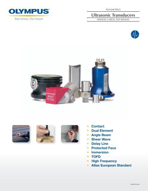
Ultrasonic Transducers<br />
WEDGES, CABLES, TEST BLOCKS<br />
• Contact<br />
• Dual Element<br />
• Angle Beam<br />
• Shear Wave<br />
• Delay Line<br />
• Protected Face<br />
• Immersion<br />
• TOFD<br />
•• High Frequency<br />
• Atlas European Standard<br />
920-041E-EN
The Company<br />
<strong>Olympus</strong> Corporation is an international company operating in<br />
industrial, medical and consumer markets, specializing in optics,<br />
electronics and precision engineering. <strong>Olympus</strong> instruments<br />
contribute to the quality of products and add to the safety of<br />
infrastructure and facilities.<br />
<strong>Olympus</strong> is a world-leading manufacturer of innovative<br />
nondestructive testing and measurement instruments that<br />
are used in industrial and research applications ranging from<br />
aerospace, power generation, petrochemical, civil infrastructure<br />
and automotive to consumer products. Leading edge testing<br />
technologies include ultrasound, ultrasound phased array, eddy<br />
current, eddy current array, microscopy, optical metrology, and<br />
X-ray fluorescence. Its products include flaw detectors, thickness<br />
gages, industrial NDT systems and scanners, videoscopes,<br />
borescopes, high-speed video cameras, microscopes, portable<br />
x-ray analyzers, probes, and various accessories.<br />
<strong>Olympus</strong> NDT is based in Waltham, Massachusetts, USA, and<br />
has sales and service centers in all principal industrial locations<br />
worldwide. Visit www.olympus-ims.com for applications and sales<br />
assistance.<br />
<strong>Panametrics</strong> Ultrasonic Transducers<br />
<strong>Panametrics</strong> <strong>ultrasonic</strong> <strong>transducers</strong> are available in<br />
more than 5000 variations in frequency, element diameter,<br />
and connector styles. With more than forty years of transducer<br />
experience, <strong>Olympus</strong> NDT has developed a wide range of<br />
custom <strong>transducers</strong> for special applications in flaw detection,<br />
weld inspection, thickness gaging, and materials analysis.<br />
Visit www.olympus-ims.com to receive your free<br />
Ultrasonic Transducer poster.
Table of Contents<br />
Transducer Selection . . . . . . . . . . . . . . . . . . . . . . . . . . . . . . 2<br />
Part Number Configurations ......................4<br />
Test and Documentation .........................5<br />
Contact Transducers. ............................6<br />
Fingertip. . . . . . . . . . . . . . . . . . . . . . . . . . . . . . . . . . . . . . .6<br />
Standard ..................................7<br />
Magnetic.Hold.Down ........................7<br />
Dual Element Transducers ........................8<br />
Flush.Case ................................8<br />
Fingertip ..................................9<br />
Extended.Range ............................9<br />
Miniature.Tip ..............................9<br />
Angle Beam Transducers and Wedges ..............10<br />
Miniature.Screw-In ........................10<br />
Standard .................................12<br />
Integral ..................................13<br />
Shear.Wave.Wedges.for.Aluminum ............13<br />
Contoured.Wedges ........................13<br />
AWS ....................................14<br />
CDS.Wedges ..............................14<br />
Normal Incidence Shear Wave Transducers ..........15<br />
Delay Line Transducers. .........................16<br />
Replaceable.Delay.Line.and.Options ..........16<br />
Sonopen®..Replaceable.Delay.Line ............17<br />
Permanent.Delay.Line.with.Handle.Assembly ...17<br />
Protected Face Transducers ......................18<br />
Immersion Transducers .........................20<br />
Standard .................................20<br />
Large.Diameter.and.Slim.Line ................21<br />
Pencil.Case,.Side.Looking.Case.and.XMS .......22<br />
Paintbrush ...............................23<br />
Reflector.Mirrors.and.Search.Tubes ...........23<br />
Bubblers.and.Bubbler.Transducers ............24<br />
RBS-1.Immersion.Tank ......................24<br />
Spot Weld Transducers. .........................25<br />
High Frequency Transducers .....................26<br />
Contact ..................................26<br />
Standard.Case.Immersion ...................27<br />
SU/RM.Case.Immersion .....................27<br />
Dual Element Transducers for Thickness Gages ......28<br />
Electromagnetic Acoustic Transducers ..............30<br />
Atlas European Standard Transducers ..............30<br />
Dual,.Contact .............................30<br />
Integral.Angle.Beam ........................31<br />
Protected.Face ............................32<br />
AVG/DCS Diagrams Binder ......................33<br />
TOFD Transducers .............................33<br />
Special Transducers ............................34<br />
Couplants and Adaptors. ........................35<br />
Test Blocks ...................................36<br />
Cables ......................................38<br />
Technical Notes ...............................40
2<br />
Transducer Selection<br />
The transducer is one of the most critical components of any<br />
<strong>ultrasonic</strong> system. A great deal of attention should be paid to<br />
selecting the proper transducer for the application.<br />
The performance of the system as a whole is of great importance.<br />
Variations in instrument characteristics and settings as well as<br />
material properties and coupling conditions play a major role in<br />
system performance.<br />
We have developed three different series of <strong>transducers</strong> to<br />
respond to the need for variety. Each series has its own unique<br />
characteristics.<br />
mV / Division<br />
0.8<br />
0.4<br />
0.0<br />
-0.4<br />
-0.8<br />
0.8<br />
0.4<br />
0.0<br />
-0.4<br />
-0.8<br />
0.8<br />
0.4<br />
0.0<br />
-0.4<br />
-0.8<br />
SIGNAL WAVEFORM<br />
( 0.2 µsec / Division )<br />
SIGNAL WAVEFORM<br />
(0.2 µsec / Division)<br />
SIGNAL WAVEFORM<br />
(0.2 µsec / Division)<br />
(VOLT)<br />
(VOLT)<br />
Accuscan “S”<br />
The Accuscan S series is intended to<br />
provide excellent sensitivity in those<br />
situations where axial resolution is<br />
not of primary importance. Typically<br />
this series will have a longer wave<br />
form duration and a relatively narrow<br />
frequency bandwidth.<br />
Centrascan<br />
The piezocomposite element Centrascan<br />
Series <strong>transducers</strong> provide<br />
excellent sensitivity with a high<br />
signal-to-noise ratio in difficultto-penetrate<br />
materials. They have<br />
exceptional acoustic matching to<br />
plastics and other low impedance<br />
materials.<br />
Videoscan<br />
Videoscan <strong>transducers</strong> are untuned<br />
<strong>transducers</strong> that provide heavily<br />
damped broadband performance.<br />
They are the best choice in applications<br />
where good axial or distance<br />
resolution is necessary or in tests that<br />
require improved signal-to-noise in<br />
attenuating or scattering materials.<br />
Transducer configuration also has an impact on system<br />
performance. Consideration should be given to the use of focused<br />
<strong>transducers</strong>, <strong>transducers</strong> with wear surfaces that are appropriate for<br />
the test material, and the choice of the appropriate frequency and<br />
element diameter.<br />
The summaries below provide a general description of the<br />
performance characteristics of each transducer series. While<br />
these guidelines are quite useful, each application is unique and<br />
performance will be dependent on electronics, cabling, and<br />
transducer configuration, frequency, and element diameter.<br />
FREQUENCY SPECTRUM<br />
Note: For more information on bandwidth and sensitivity versus resolution, please refer to the Technical Notes located on pages 41-50.<br />
Note: For sample test forms of <strong>transducers</strong> that you are interested in purchasing or if you have questions, please contact us via phone,<br />
fax, or e-mail.<br />
1.0<br />
0.8<br />
0.6<br />
0.4<br />
0.2<br />
1.0<br />
0.8<br />
0.6<br />
0.4<br />
0.2<br />
2.25<br />
FREQUENCY SPECTRUM<br />
3.85<br />
-6 dB<br />
0.0<br />
0 5<br />
(MHz)<br />
10<br />
0<br />
-10<br />
dB -20<br />
-30<br />
-40<br />
2.67<br />
-6 dB<br />
0.0<br />
0 5<br />
(MHz)<br />
10<br />
6.2<br />
FREQUENCY SPECTRUM<br />
-50<br />
0 5<br />
(MHz)<br />
10<br />
7.0<br />
7.8
Transducer Selection<br />
www.olympus-ims.com<br />
Contact Transducers: A contact transducer is a single element transducer, usually generating a longitudinal<br />
wave, that is intended for direct contact with a test piece. All contact <strong>transducers</strong> are equipped<br />
with a WC5 wear face that offers superior wear resistance and probe life as well as providing an excellent<br />
acoustic impedance match to most metals. Please see page 6 for more details on longitudinal<br />
contact probes or page 15 for information on normal incidence shear wave <strong>transducers</strong>.<br />
Dual Element Transducers: A dual element transducer consists of two longitudinal wave crystal elements<br />
(one transmitter and one receiver) housed in the same case and isolated from one another by<br />
an acoustic barrier. The elements are angled slightly towards each other to bounce a signal off the<br />
backwall of a part in a V-shaped pattern. Dual element <strong>transducers</strong> typically offer more consistent<br />
readings on heavily corroded parts, and can also be used in high temperature environments. See page<br />
8 for more information on dual element <strong>transducers</strong> for flaw detection or page 30 for dual element<br />
probes for use with <strong>Olympus</strong> NDT corrosion gages.<br />
Angle Beam Transducers: Angle beam <strong>transducers</strong> are single element <strong>transducers</strong> used with a wedge<br />
to introduce longitudinal or shear wave sound into a part at a selected angle. Angle beam <strong>transducers</strong><br />
allow inspections in areas of a part that cannot be accessed by the <strong>ultrasonic</strong> path of a normal<br />
incidence contact transducer. A common use for angle beam <strong>transducers</strong> is in weld inspection, where<br />
a weld crown blocks access to the weld zone of interest for a standard contact transducer and where<br />
typical flaw alignment produces stronger reflections from an angled beam. Please see page 10 for<br />
additional information on angle beam <strong>transducers</strong> and wedges. For a detailed explanation of how<br />
wedges are designed using Snell’s Law please see page 46 of the Technical Notes.<br />
Delay Line Transducers: Delay line <strong>transducers</strong> are single element broadband contact <strong>transducers</strong> designed<br />
specifically to incorporate a short piece of plastic or epoxy material in front of the transducer<br />
element. Delay lines offer improved resolution of flaws very near to the surface of a part and allow<br />
thinner range and more accurate thickness measurements of materials. Delay lines can be contoured<br />
to match the surface geometry of a part and can also be used in high temperature applications. For<br />
more information on delay line <strong>transducers</strong> and delay line options, please see page 16.<br />
Protected Face Transducers: Protected face <strong>transducers</strong> are single element longitudinal wave <strong>transducers</strong><br />
with threaded case sleeves, which allow for a delay line, wear cap, or membrane. This makes<br />
them extremely versatile and able to cover a very wide range of applications. Protected face <strong>transducers</strong><br />
can also be used as a direct contact transducer on lower impedance materials such as rubber<br />
or plastic for an improved acoustic impedance match. Please see page 18 for more information on<br />
protected face <strong>transducers</strong> and the options available for use with them.<br />
Immersion Transducers: Immersion <strong>transducers</strong> are single element longitudinal wave <strong>transducers</strong>,<br />
whose wear face is impedance matched to water. Immersion <strong>transducers</strong> have sealed cases allowing<br />
them to be completely submerged under water when used with a waterproof cable. By using water<br />
as both a couplant and delay line, immersion <strong>transducers</strong> are ideal for use in scanning applications<br />
where consistent coupling to the part is essential. As an additional option, immersion <strong>transducers</strong><br />
can also be focused to increase the sound intensity in a specific area and decrease the spot size of<br />
the sound beam. For additional information on immersion <strong>transducers</strong>, please see page 20. For an in<br />
depth explanation of focusing, please see page 46 of the Technical Notes.<br />
High Frequency Transducers: High frequency <strong>transducers</strong> are either delay line or focused immersion<br />
<strong>transducers</strong> and are available in frequencies from 20 MHz to 225 MHz. High frequency delay line<br />
<strong>transducers</strong> are capable of making thickness measurements on materials as thin as 0.0004 in.<br />
(0.010 mm) (dependent on material, transducer, surface condition, temperature, and setup), while<br />
high frequency focused immersion <strong>transducers</strong> are ideal for high resolution imaging and flaw detection<br />
applications on thin, low attenuation materials such as silicon microchips. For more information<br />
on all high frequency <strong>transducers</strong>, please see page 26.<br />
3
4<br />
Part Number Configurations<br />
Connector Style<br />
RM<br />
RB<br />
Right Angle BNC<br />
Right Angle<br />
Microdot<br />
SM<br />
Straight<br />
Microdot<br />
Part number example V109-RM<br />
Contoured<br />
Delays<br />
CC-R<br />
Concave<br />
Radius<br />
CX-R<br />
Convex<br />
Radius<br />
Part number<br />
example<br />
DLH-1-CC-R1.25IN<br />
SB<br />
Straight BNC<br />
SU<br />
Straight UHF<br />
Contoured<br />
Wedges<br />
AID AOD<br />
Axial Inside<br />
Diameter<br />
CID<br />
Circumferential<br />
Inside Diameter<br />
Axial Outside<br />
Diameter<br />
COD<br />
Circumferential<br />
Outside Diameter<br />
Part number example<br />
ABWM-4T-45-COD-1.25IN<br />
Focal Types<br />
(Immersion Transducers)<br />
F<br />
Spherical Focus<br />
RPL1<br />
Right Angle Potted<br />
Cable Terminating in<br />
LEMO 1 Connectors<br />
RP<br />
Right Angle Potted<br />
Cable Terminating in<br />
BNC Connectors<br />
Focal Designations<br />
FPF Flat Plate Focus<br />
OLF Optical Limit Focus<br />
PTF Point Target Focus<br />
Part number example<br />
V309-SU-F1.00IN-PTF<br />
CF<br />
Cylindrical Focus
Test and Documentation<br />
<strong>Olympus</strong> NDT is an active leader in the development of transducer<br />
characterization techniques and has participated in the<br />
development of the ASTM-E 1065 Standard Guide for Evaluating<br />
Characteristics of Ultrasonic Search Units. In addition, we have<br />
performed characterizations according to AWS and EN12668-2.<br />
As part of the documentation process, an extensive database containing<br />
records of the waveform and spectrum of each transducer<br />
Standard Test Forms (TP103)<br />
TP103, or standard test form, records the actual RF<br />
waveform and frequency spectrum for each transducer.<br />
Each test form has measurements of the peak and<br />
center frequencies, upper and lower -6 dB frequencies,<br />
bandwidth, and waveform duration according to<br />
ASTM-E 1065. The TP103 test form is included at no<br />
extra charge on all types of Accuscan, Centrascan, and<br />
Videoscan <strong>transducers</strong>.<br />
Beam Profiles (TP101)<br />
TP101, or axial beam profile, is created by recording<br />
the amplitude of the sound field as a function of<br />
distance from the transducer face along the acoustic<br />
axis. This provides information on the depth of field,<br />
near field, or focal length of the probe. It can be<br />
generated from any type of immersion transducer.<br />
www.olympus-ims.com<br />
is maintained and can be accessed for comparative or statistical<br />
studies of transducer characteristics. Our test lab offers a variety of<br />
documentation services including waveform and spectrum analysis,<br />
axial and transverse beam profiles, and electrical impedance<br />
plots. Please consult us concerning special testing requirements.<br />
Electrical Impedance Plots (TP104)<br />
TP104, or electrical impedance plot, provides information<br />
on the electrical characteristics of a transducer and<br />
how it loads a pulser. The TP104 displays the impedance<br />
magnitude versus frequency and the phase angle<br />
versus frequency. It can be generated from most types of<br />
<strong>transducers</strong>.<br />
Beam Profiles (TP102)<br />
TP102, or transverse beam profile, is created by<br />
recording the amplitude of the sound field as the<br />
transducer is moved across a ball target in a plane<br />
parallel to the transducer face. This is done at a set<br />
distance from the transducer, typically at the near<br />
field or focal length distance, and in both X and Y<br />
axes. It can be generated from any type of immersion<br />
transducer.<br />
5
6<br />
Contact Transducers<br />
A contact transducer is a single element longitudinal wave<br />
transducer intended for use in direct contact with a test piece.<br />
Advantages<br />
• Proprietary WC-5 wear plate increases durability, fracture<br />
resistance, and wear resistance<br />
• All styles are designed for use in rugged industrial<br />
environments<br />
• Close acoustic impedance matching to most metals<br />
• Can be used to test a wide variety of materials<br />
Applications<br />
• Straight beam flaw detection and thickness gaging<br />
• Detection and sizing of delaminations<br />
• Material characterization and sound velocity measurements<br />
• Inspection of plates, billets, bars, forgings, castings,<br />
extrusions, and a wide variety of other metallic and<br />
non-metallic components<br />
• For continuous use on materials up to 122 °F (50 °C)<br />
Fingertip Contact<br />
• Units larger than 0.25 in. (6 mm) are knurled for easier grip<br />
• 303 stainless steel case<br />
• Low profile for difficult-to-access surfaces<br />
• Removable plastic sleeve for better grip available upon<br />
request at no additional charge, part number CAP4 for<br />
0.25 in. (6 mm) and CAP8 for 0.125 in. (3 mm)<br />
• Standard configuration is Right Angle and fits Microdot<br />
connector<br />
V106-RM<br />
A110S-SM<br />
V113-SM<br />
Transducer Dimensions<br />
(in inches)<br />
Nominal Element<br />
Size<br />
V110-RM<br />
(A) (B)<br />
1.00 1.25 0.63<br />
0.75 1.00 0.63<br />
0.50 0.70 0.63<br />
0.375 0.53 0.50<br />
0.25 0.35 0.42<br />
0.125 0.25 0.38<br />
V116-RM<br />
Freq<br />
Nominal<br />
Element Size<br />
Transducer Part Numbers<br />
MHz in. mm ACCUSCAN-S CENTRASCAN VIDEOSCAN<br />
0.5 1.00 25 A101S-RM — V101-RM<br />
1.00 25 A102S-RM — V102-RM<br />
1.0 0.75 19 A114S-RM — V114-RM<br />
0.50 13 A103S-RM — V103-RM<br />
1.00 25 A104S-RM — V104-RM<br />
0.75 19 A105S-RM — V105-RM<br />
2.25 0.50 13 A106S-RM C106-RM V106-RM<br />
0.375 10 A125S-RM C125-RM V125-RM<br />
0.25 6 A133S-RM C133-RM V133-RM<br />
1.00 25 A180S-RM — —<br />
0.75 19 A181S-RM — V181-RM<br />
3.5 0.5 13 A182S-RM — V182-RM<br />
0.375 10 A183S-RM — V183-RM<br />
0.25 6 A184S-RM — —<br />
1.00 25 A107S-RM — V107-RM<br />
0.75 19 A108S-RM — V108-RM<br />
5.0<br />
0.50<br />
0.375<br />
13<br />
10<br />
A109S-RM<br />
A126S-RM<br />
C109-RM<br />
C126-RM<br />
V109-RM<br />
V126-RM<br />
0.25 6 A110S-RM C110-RM V110-RM<br />
0.125 3 — — V1091<br />
0.50 13 A120S-RM — —<br />
7.5 0.375 10 A122S-RM — V122-RM<br />
0.25 6 A121S-RM — V121-RM<br />
0.50 13 A111S-RM — V111-RM<br />
10<br />
0.375<br />
0.25<br />
10<br />
6<br />
A127S-RM<br />
A112S-RM<br />
—<br />
—<br />
V127-RM<br />
V112-RM<br />
0.125 3 — — V129-RM<br />
15 0.25 6 A113S-RM — V113-RM<br />
20 0.125 3 — — V116-RM
Standard Contact<br />
• Comfort Fit sleeves designed to be easily held and to provide a<br />
steady grip while wearing gloves<br />
• 303 stainless steel case<br />
• Large element diameters for increased sound energy and<br />
greater coverage<br />
• Standard connector style is Right Angle BNC (RB), may be<br />
available in a Straight BNC (SB)<br />
Frequency<br />
Nominal<br />
Element Size<br />
www.olympus-ims.com<br />
Transducer Part Numbers<br />
MHz inches mm ACCUSCAN-S VIDEOSCAN<br />
0.1 1.50 38 — V1011<br />
0.25 1.50 38 — V1012<br />
0.5<br />
1.0<br />
1.5 38 A189S-RB V189-RB<br />
1.125 29 A191S-RB V191-RB<br />
1.00 25 A101S-RB V101-RB<br />
1.50 38 A192S-RB V192-RB<br />
1.125 29 A194S-RB V194-RB<br />
1.00 25 A102S-RB V102-RB<br />
0.75 19 A114S-RB V114-RB CENTRASCAN<br />
0.50 13 A103S-RB V103-RB C103-SB<br />
1.5 38 A195S-RB V195-RB<br />
1.125 29 A197S-RB V197-RB<br />
2.25<br />
1.00<br />
0.75<br />
25<br />
19<br />
A104S-RB<br />
A105S-RB<br />
V104-RB<br />
V105-RB<br />
0.50 13 A106S-RB V106-RB<br />
0.25 x 1 6 x 25 A188S-RB* —<br />
1.00 25 A180S-RB V180-RB<br />
3.5 0.75 19 A181S-RB V181-RB<br />
0.50 13 A182S-RB V182-RB<br />
1.00 25 A107S-RB V107-RB<br />
5.0 0.75 19 A108S-RB V108-RB<br />
0.50 13 A109S-RB V109-RB<br />
7.5 0.50 13 A120S-RB V120-RB<br />
10 0.50 13 A111S-RB V111-RB<br />
*Per ASTM Standard A-418<br />
Magnetic Hold Down Contact<br />
• Magnetic ring around transducer case for stationary positioning<br />
on ferrous materials<br />
• Broadband performance similar to Videoscan series<br />
Frequency Nominal Element Size Part Number<br />
MHz inches mm<br />
5.0<br />
0.5<br />
0.25<br />
13<br />
6<br />
M1042<br />
M1057<br />
10<br />
0.5<br />
0.25<br />
13<br />
6<br />
M1056<br />
M1054<br />
15 0.25 6 M1055<br />
Note: All above magnetic hold down <strong>transducers</strong> have straight Microdot connectors.<br />
V105-SB<br />
Nominal<br />
Element Size<br />
Transducer Dimensions<br />
(in inches)<br />
(A) (B) (C)<br />
1.50 1.75 2.23 1.25<br />
1.50* 1.75 2.50 2.50<br />
1.125 1.38 1.79 1.25<br />
1.00 1.25 1.60 1.25<br />
0.25 x 1.00 1.25 1.60 1.25<br />
0.75 1.00 1.37 1.25<br />
0.50 0.63 1.16 1.25<br />
*V1011 and V1012 housed in different case.<br />
M1057<br />
V104-RB<br />
M1057<br />
Transducer Dimensions<br />
(in inches)<br />
Nominal Element Size (A) (B)<br />
0.50 0.81 0.63<br />
0.25 0.50 0.42<br />
V103-RB<br />
7
8<br />
Dual Element Transducers<br />
A dual element transducer consists of two crystal elements housed<br />
in the same case, separated by an acoustic barrier. One element<br />
transmits longitudinal waves, and the other element acts as a<br />
receiver.<br />
For information on <strong>transducers</strong> for MG2 and 37 Series thickness<br />
gages, see pages 28-29.<br />
Advantages<br />
• Improves near surface resolution<br />
• Eliminates delay line multiples for high temperature<br />
applications<br />
• Couples well on rough or curved surfaces<br />
• Reduces direct back-scattering noise in coarse grained or<br />
scattering materials<br />
• Combines penetration capabilities of a lower frequency single<br />
element transducer with the near surface resolution capabilities<br />
of a higher frequency single element transducer<br />
• Can be contoured to conform to curved parts<br />
Applications<br />
• Remaining wall thickness measurement<br />
• Corrosion/erosion monitoring<br />
• Weld overlay and cladding bond/disbond inspection<br />
• Detection of porosity, inclusions, cracks, and laminations in<br />
castings and forgings<br />
• Crack detection in bolts or other cylindrical objects<br />
• Maximum temperature capability is 800 °F (425 °C) for 5.0<br />
MHz and below; 350 °F (175 °C) for 7.5 MHz and 10 MHz.<br />
Recommended duty cycle for surface temperatures from<br />
200 °F (90 °C) to 800 °F (425 °C) is ten seconds maximum<br />
contact followed by a minimum of one minute air cooling<br />
(does not apply to Miniature Tip Dual)<br />
Flush Case Duals<br />
• Metal wear ring extends transducer life<br />
• Wear indicator references when transducer face needs<br />
resurfacing<br />
• Knurled, 303 stainless steel case<br />
• Replaceable cable design (special dual cables with strain relief<br />
available)<br />
Frequency<br />
Nominal<br />
Element Size<br />
MHz inches mm<br />
Transducer<br />
Part Numbers<br />
1.0 0.50 13 DHC703-RM<br />
2.25<br />
0.50<br />
0.25<br />
13<br />
6<br />
DHC706-RM<br />
DHC785-RM<br />
5.0<br />
0.50<br />
0.25<br />
13<br />
6<br />
DHC709-RM<br />
DHC711-RM<br />
10 0.25 6 DHC713-RM<br />
Two angled elements create a V-shaped sound path in the<br />
test material. This pseudo-focus enhances resolution in the<br />
focal zone.<br />
Flush Case Dual Cables<br />
Cable Part Number Fits Connector Style<br />
BCMD-316-5F Dual BNC to Microdot<br />
L1CMD-316-5F Dual Large LEMO 1 to Microdot<br />
LCMD-316-5F Dual Small LEMO 00 to Microdot<br />
BCMD-316-5F<br />
DHC709-RM<br />
Composite Element Flush Case Duals<br />
Frequency<br />
Nominal<br />
Element Size<br />
Transducer Part Number<br />
MHz inches mm<br />
2.25 0.50 13 CHC706-RM<br />
0.25" Element size 0.50" Element Size<br />
DHC711-RM<br />
DHC706-RM
Fingertip Duals<br />
• Knurled case, except the 0.25 in. (6 mm) element size<br />
• High-strength flexible 6 ft (1.8 m) potted cable (fits BNC or<br />
Large LEMO 1 connectors)<br />
Frequency<br />
Nominal<br />
Element Size<br />
MHz inches mm<br />
Miniature Tip Dual<br />
• Provides better coupling on curved surfaces<br />
• Low profile allows for better access in areas of limited space<br />
• Maximum temperature capability 122 °F (50 °C)<br />
www.olympus-ims.com<br />
Fits BNC<br />
Connector<br />
Transducer<br />
Part Numbers<br />
Fits Large LEMO<br />
Connector<br />
1.0 0.75 19 D714-RP D714-RPL1<br />
0.50 13 D703-RP D703-RPL1<br />
2.25 0.75 19 D705-RP D705-RPL1<br />
0.50 13 D706-RP D706-RPL1<br />
0.375 10 D771-RP D771-RPL1<br />
0.25 6 D785-RP D785-RPL1<br />
3.5 0.75 19 D781-RP D781-RPL1<br />
0.50 13 D782-RP D782-RPL1<br />
0.375 10 D783-RP D783-RPL1<br />
0.25 6 D784-RP D784-RPL1<br />
5.0 0.75 19 D708-RP D708-RPL1<br />
0.50 13 D709-RP D709-RPL1<br />
0.375 10 D710-RP D710-RPL1<br />
0.25 6 D711-RP D711-RPL1<br />
7.5 0.50 13 D720-RP D720-RPL1<br />
0.25 6 D721-RP D721-RPL1<br />
10 0.50 13 D712-RP D712-RPL1<br />
0.25 6 D713-RP D713-RPL1<br />
Frequency<br />
Tip<br />
Diameter<br />
Nominal<br />
Element Size<br />
Transducer<br />
Part Number<br />
MHz inches mm inches mm<br />
5.0 0.20 5 0.15 3.8 MTD705<br />
Miniature Tip Dual Cables<br />
• Replaceable cable for all flaw detectors<br />
Cable Part Number Fits Connector Style<br />
BCLPD-78-5 Dual BNC to Lepra/Con<br />
L1CLPD-78-5 Dual Large LEMO 1 to Lepra/Con<br />
LCLPD-78-5 Dual Small LEMO 00 to Lepra/Con<br />
Extended Range Duals<br />
• Shallow roof angles provide greater sensitivity to deep flaws,<br />
back walls, and other reflectors, 0.75 in. (19 mm) and beyond<br />
in steel<br />
• Can be used for high temperature measurements when delay<br />
lines are unacceptable<br />
• High-strength flexible 6 ft (1.8 m) potted cable with BNC<br />
connectors<br />
Frequency<br />
Nominal<br />
Element Size<br />
Roof Angle<br />
MHz inches mm (°)<br />
2.25<br />
5.0<br />
Nominal<br />
Element Size<br />
Transducer Dimensions<br />
(in inches)<br />
Transducer<br />
Part Numbers<br />
1.00 25 0 D7079<br />
0.50 13 0 D7071<br />
0.50 13 1.5 D7072<br />
0.50 13 2.6 D7074<br />
0.50 13 3.5 D7073<br />
1.00 25 0 D7080<br />
0.50 13 0 D7075<br />
0.50 13 1.5 D7076<br />
0.50 13 2.6 D7078<br />
0.50 13 3.5 D7077<br />
Fingertip and<br />
Extended Range Dual<br />
(A) (B) (C)<br />
1.00* 1.25 0.75 1.00<br />
0.75 1.00 0.75 0.75<br />
0.50 0.70 0.75 0.50<br />
0.50* 0.70 0.63 0.61<br />
0.375 0.53 0.62 0.375<br />
0.25 0.35 0.54 0.25<br />
* Extended Range Duals<br />
Miniature Tip Dual<br />
BCLPD-78-5<br />
MTD705<br />
D705-RP<br />
D706-RP<br />
D711-RP<br />
9
10<br />
Angle Beam Transducers<br />
Angle beam <strong>transducers</strong> are single element <strong>transducers</strong> used with<br />
a wedge to introduce a refracted shear wave or longitudinal wave<br />
into a test piece.<br />
Advantages<br />
• Three-material design of our Accupath wedges improves<br />
signal-to-noise characteristics while providing excellent wear<br />
resistance<br />
• High temperature wedges available for in-service inspection of<br />
hot materials<br />
• Wedges can be customized to create nonstandard refracted<br />
angles<br />
• Available in interchangeable or integral designs<br />
• Contouring available<br />
• Wedges and integral designs are available with standard<br />
refracted angles in aluminum (see page 13).<br />
Applications<br />
• Flaw detection and sizing<br />
• For time-of-flight diffraction <strong>transducers</strong>, see page 33.<br />
• Inspection of pipes, tubes, forgings, castings, as well as<br />
machined and structural components for weld defects or cracks<br />
Miniature Screw-In Transducers<br />
• Screw-in design 303 stainless steel case<br />
• Transducers are color coded by frequency<br />
• Compatible with Short Approach, Accupath,<br />
High Temperature, and Surface Wave Wedges<br />
Note: Miniature snap-in <strong>transducers</strong> available by request.<br />
Nominal<br />
Element Size<br />
Frequency Transducer Part Numbers<br />
inches mm MHz ACCUSCAN-S CENTRASCAN VIDEOSCAN<br />
0.50 13<br />
0.375 10<br />
0.25 6<br />
C540-SM<br />
ABSA-5T-X°<br />
1.0 A539S-SM C539-SM V539-SM<br />
2.25 A540S-SM C540-SM V540-SM<br />
3.5 A545S-SM C545-SM V545-SM<br />
5.0 A541S-SM C541-SM V541-SM<br />
10 A547S-SM — V547-SM<br />
1.0 — C548-SM —<br />
1.5 A548S-SM — —<br />
2.25 A549S-SM C549-SM V549-SM<br />
3.5 A550S-SM C550-SM V550-SM<br />
5.0 A551S-SM C551-SM V551-SM<br />
10 A552S-SM — V552-SM<br />
2.25 A542S-SM C542-SM V542-SM<br />
3.5 A546S-SM C546-SM V546-SM<br />
5.0 A543S-SM C543-SM V543-SM<br />
10 A544S-SM C544-SM V544-SM<br />
Miniature angle beam <strong>transducers</strong> and wedges are used<br />
primarily for testing of weld integrity. Their design allows<br />
them to be easily scanned back and forth and provides a<br />
short approach distance.<br />
V540-SM<br />
ABWM-5T-X°<br />
Nominal<br />
Element Size<br />
A551S-SM<br />
C543-SM<br />
ABWM-4T-X°<br />
Trasnducer Dimensions<br />
(in inches)<br />
(A) (B) (C) Thread Pitch<br />
0.50 0.71 0.685 0.257 11/16 - 24<br />
0.375 0.58 0.65 0.257 9/16 - 24<br />
0.25 0.44 0.55 0.22 3/8 - 32<br />
ABSA-5T-X°
Short Approach Wedges<br />
• Smallest footprint<br />
• Short approach distance allows for inspection closest to the<br />
weld crown<br />
ABSA-7T-X°<br />
Miniature Screw-In Wedges for 1-5 MHz<br />
Nominal<br />
Element Size<br />
ABSA-5T-X°<br />
inches mm Short Approach † Accupath*<br />
Miniature Screw-In Wedges for 10 MHz Transducers<br />
Nominal<br />
Element Size<br />
Wedge Part Numbers<br />
inches mm Accupath* Surface Wave 90°<br />
0.50 13 ABWM-5ST-X° ABWML-5ST-90°<br />
0.375 10 ABWM-7ST-X° ABWML-7ST-90°<br />
0.25 6 ABWM-4ST-X° ABWML-4ST-90°<br />
www.olympus-ims.com<br />
ABSA-4T-X°<br />
ABSA-5T-X°<br />
Wedge Part Numbers<br />
High Temp*<br />
500 °F (260 °C)<br />
Accupath Wedges<br />
• Small wedge footprint<br />
• Pointed toe design allows transducer rotation even when the<br />
nose is touching a weld crown<br />
• Special wedge design for use with 10 MHz transducer<br />
Very High Temp*<br />
900 °F (480 °C)<br />
Surface Wave 90°<br />
0.50 13 ABSA-5T-X° ABWM-5T-X° ABWHT-5T-X° ABWVHT-5T-X° ABWML-5T-90°<br />
0.375 10 ABSA-7T-X° ABWM-7T-X° ABWHT-7T-X° ABWVHT-7T-X° ABWML-7T-90°<br />
0.25 6 ABSA-4T-X° ABWM-4T-X° ABWHT-4T-X° ABWVHT-4T-X° ABWML-4T-90°<br />
Short Approach Wedge Dimensions (Miniature Screw-in)<br />
Fits Nominal Element Size (in inches)<br />
0.5 0.375 0.25<br />
(A) (B) (C) (D) (A) (B) (C) (D) (A) (B) (C) (D)<br />
45° 0.70 1.03 0.73 0.38 0.60 0.85 0.61 0.32 0.43 0.61 0.43 0.235<br />
60° 0.74 1.19 0.73 0.45 0.67 1.00 0.61 0.367 0.48 0.71 0.43 0.268<br />
70° 0.79 1.34 0.73 0.50 0.69 1.12 0.61 0.406 0.50 0.81 0.43 0.305<br />
Accupath and Surface Wave Wedge Dimensions* (Miniature Screw-in)<br />
Fits Nominal Element Size (in inches)<br />
0.5 0.375 0.25<br />
(A) (B) (C) (D) (A) (B) (C) (D) (A) (B) (C) (D)<br />
30° 0.72 1.22 0.77 0.54 0.62 1.03 0.65 0.42 0.49 0.66 0.45 0.23<br />
45° 0.85 1.31 0.77 0.49 0.76 1.14 0.65 0.41 0.53 0.74 0.45 0.24<br />
60° 1.00 1.66 0.77 0.66 0.87 1.41 0.65 0.52 0.63 0.95 0.45 0.32<br />
70° 1.00 1.82 0.77 0.73 0.92 1.52 0.65 0.51 0.66 1.08 0.45 0.36<br />
90° 1.25 1.84 0.77 — 1.00 1.48 0.65 — 0.83 1.13 0.45 —<br />
*Wedge dimensions for 10 MHz <strong>transducers</strong> are slightly different; please consult us for details.<br />
ABWM-4T-X°<br />
ABWM-7T-X°<br />
*Accupath Wedges are available in standard<br />
refracted shear wave angles of 30°,<br />
45°, 60°, and 70° in steel at 10 MHz.<br />
ABWM-5T-X°<br />
† Short Approach Wedges are available in<br />
standard refracted shear wave angles of<br />
45°, 60°, and 70° in steel at 5.0 MHz.<br />
*Accupath Wedges are available in standard<br />
refracted shear wave angles of 30°,<br />
45°, 60°, and 70° in steel at 5.0 MHz.<br />
11
12<br />
Standard Angle Beam<br />
Transducers and Wedges<br />
• Large element size allows for inspection of thicker<br />
components and provides a large scanning index<br />
• Transducers available in Accuscan-S, Centrascan,<br />
and Videoscan Series<br />
• Accupath and high temperature style wedges<br />
available<br />
• Threaded brass screw receptacles ensure firm<br />
anchoring of the transducer onto the wedge.<br />
• Available in frequencies as low as 0.5 MHz and<br />
1.0 MHz<br />
• Captive screws included with the transducer<br />
Nominal<br />
Element Size<br />
Standard Angle Beam<br />
<strong>transducers</strong> and<br />
wedges offer a large<br />
scanning index, which<br />
allows for a shorter<br />
scan time on larger<br />
test surfaces.<br />
Frequency Transducer Part Numbers Wedge Part Numbers<br />
inches mm MHz ACCUSCAN-S CENTRASCAN VIDEOSCAN Accupath*<br />
0.5 A414S-SB — V414-SB<br />
1.0 A407S-SB C407-SM V407-SB<br />
1.00 25 2.25 A408S-SB C408-SB V408-SB<br />
3.5 A411S-SB C411-SB —<br />
5.0 A409S-SB — V409-SB<br />
0.5 A413S-SB — V413-SB<br />
0.50 13<br />
1.0 A401S-SB C401-SB V401-SB<br />
x x 2.25 A403S-SB C403-SB V403-SB<br />
1.00 25<br />
3.5 A412S-SB C412-SB —<br />
5.0 A405S-SB C405-SB V405-SB<br />
1.0 A402S-SB C402-SB V402-SB<br />
0.50 13<br />
2.25<br />
3.5<br />
A404S-SB<br />
A415S-SB<br />
C404-SB<br />
C415-SB<br />
V404-SB<br />
—<br />
5.0 A406S-SB C406-SB V406-SB<br />
*Wedges are available in standard refracted shear wave angles of 30°, 45°, 60°, and 70° in steel at 5.0 MHz.<br />
Dimension A = Wedge Height<br />
Dimension D = Approach Distance<br />
ABWS-2-X°<br />
ABWS-1-X°<br />
ABWS-1-X°<br />
Accupath and Surface Wave Wedge Dimensions (Standard)<br />
Nominal Element Size (in inches)<br />
High Temp*<br />
500 °F (260 °C)<br />
Very High<br />
Temp* 900 °F<br />
(480 °C)<br />
Surface Wave<br />
90°<br />
ABWS-3-X° ABWHT-3-X° ABWVHT-3-X° ABWSL-3-90°<br />
ABWS-2-X° ABWHT-2-X° ABWVHT-2-X° ABWSL-2-90°<br />
ABWS-1-X° ABWHT-1-X° ABWVHT-1-X° ABWSL-1-90°<br />
1.00 0.50 x 1.00 0.50<br />
(A) (B) (C) (D) (A) (B) (C) (D) (A) (B) (C) (D)<br />
30° 1.69 2.15 1.62 1.15 1.30 1.30 1.60 0.76 1.20 1.42 1.10 0.83<br />
45° 1.47 1.96 1.63 0.97 1.30 1.41 1.60 0.78 1.20 1.31 1.08 0.70<br />
60° 1.50 2.18 1.63 1.00 1.30 1.50 1.60 0.67 1.20 1.48 1.08 0.68<br />
70° 1.50 2.47 1.63 1.13 1.35 1.77 1.60 0.85 1.20 1.58 1.09 0.68<br />
90° 1.50 2.50 1.65 0.44 1.20 1.34 1.60 — 1.20 1.34 1.00 —<br />
Transducer Dimensions<br />
(in inches)<br />
Nominal<br />
Element Size<br />
(A) (B) (C) (D)<br />
1.00 1.25 0.63 1.38 1.65<br />
0.50 x 1.00 0.73 0.63 1.31 1.53<br />
0.50 0.72 0.63 0.81 1.02
Integral Angle Beam Transducers<br />
• Durable plastic wear surface extends transducer life and avoids<br />
scratching of critical components.<br />
• Small approach distance and overall transducer height<br />
provides an excellent choice for limited access applications.<br />
• Superior signal-to-noise characteristics for such small integral<br />
<strong>transducers</strong><br />
• Finger ring included with Micro-Miniature-RM case style<br />
<strong>transducers</strong><br />
Transducer<br />
Case<br />
Miniature<br />
Micro-Miniature<br />
*A564S-RM, A574S-RM, and A5053 create surface waves in steel and aluminum.<br />
Shear Wave Wedges for Aluminum<br />
• Compatible with our Miniature Screw-In and Standard Angle Beam <strong>transducers</strong><br />
Transducer<br />
Case<br />
Screw-In<br />
Standard<br />
Contoured Wedges<br />
• Improve coupling on curved surfaces<br />
• When ordering, please specify wedge type, contour orientation, and contour diameter.<br />
• Example Part #: ABWM-4T-45-COD-1.25IN<br />
www.olympus-ims.com<br />
Nominal<br />
Element Size<br />
Frequency Material<br />
Connector<br />
Style<br />
0.25"<br />
RM STYLE<br />
for Aluminum<br />
Transducer Part Numbers<br />
inches mm MHz 45° 60° 70° 90°<br />
0.25 6<br />
2.25 Steel RM A561S-RM A562S-RM A563S-RM A564S-RM*<br />
x x 5.0 Steel RM A571S-RM A572S-RM A573S-RM A574S-RM*<br />
0.25 6<br />
5.0 Aluminum RM or SM A591S A592S A593S see note*<br />
2.25 Steel RM A5050 — — A5053*<br />
0.187<br />
x<br />
0.187<br />
5<br />
x<br />
5<br />
0.25"<br />
SM STYLE<br />
for Aluminum<br />
A592S-SM<br />
5.0 Steel RM A5020 A5023 A5021 —<br />
5.0 Steel SM A5015 A5014 A5013 —<br />
5.0 Aluminum SM A5067 A5068 A5069 see note*<br />
10 Steel SM — — A5054 —<br />
0.187", RM STYLE A5023 0.187", SM STYLE A5014 0.25", RM STYLE<br />
for Steel<br />
AID<br />
(Axial Inside Diameter)<br />
Nominal<br />
Element Size<br />
Wedge Part Numbers<br />
inches mm 30° 45° 60° 70° 90°<br />
0.50 13 ABWM-5053T ABWM-5027T ABWM-5028T ABWM-5029T ABWML-5041T<br />
0.375 10 ABWM-7024T ABWM-7025T ABWM-7026T ABWM-7027T ABWML-7028T<br />
0.25 6 ABWM-4086T ABWM-4087T ABWM-4088T ABWM-4089T ABWML-4074T<br />
1.00 25 ABWS-3028 ABWS-3016 ABWS-3029 ABWS-3030 ABWSL-3039<br />
0.50 x 1.00 13 x 25 ABWS-2021 ABWS-2022 ABWS-2023 ABWS-2024 ABWSL-2056<br />
0.50 13 ABWS-1033 ABWS-1034 ABWS-1035 ABWS-1036 ABWSL-1045<br />
AOD<br />
(Axial Outside Diameter)<br />
CID<br />
(Circumferential Inside Diameter)<br />
A592S-RM<br />
A564S-RM<br />
COD<br />
(Circumferential Outside Diameter)<br />
13
14<br />
AWS Wedges and Transducers<br />
• Transducers and wedges meet or exceed the<br />
specifications as set forth by the AWS Code<br />
Section D1.1.<br />
• Snail wedges use industry accepted hole spacing.<br />
• Captive screws included with the transducer<br />
• Accupath style wedges marked with a five line<br />
graticule to assist in locating the beam exit point<br />
ABWS-8-X°<br />
Snail Wedge Dimensions*<br />
(in inches)<br />
(A) (B) (C) (D)<br />
45° 2.15 0.62 1.78 1.25<br />
60° 1.91 0.65 1.81 1.25<br />
70° 2.17 0.67 1.92 1.25<br />
CDS Wedges<br />
CDS Wedges are used in the “30-70-70” technique<br />
for crack detection and sizing. They are compatible<br />
with our replaceable miniature screw-in angle beam<br />
<strong>transducers</strong>, making them an economical alternative<br />
to other commercially available products.<br />
For <strong>transducers</strong>, see page 10.<br />
Nominal<br />
Element Size<br />
Frequency<br />
Transducer<br />
Part Numbers<br />
inches MHz ACCUSCAN CENTRASCAN<br />
0.625 x 0.625<br />
A430S-SB C430-SB<br />
0.625 x 0.75 2.25 A431S-SB C431-SB<br />
0.75 x 0.75 A432S-SB C432-SB<br />
Snail<br />
Wedge Part<br />
Number*<br />
Accupath<br />
Wedge Part<br />
Number*<br />
ABWS-8 -X° ABWS-6-X°<br />
* Wedges are available in standard refracted shear wave angles of 45°, 60° and 70° in steel. Please specify upon ordering.<br />
Snail Wedges Accupath Wedges<br />
* Distance between screws (center to center) is<br />
1.00 in.<br />
C430-SB C432-SB<br />
Fits Nominal<br />
Element Size<br />
inches mm<br />
Wedge Part<br />
Number<br />
0.25 6 CDS-4T<br />
0.375 10 CDS-7T<br />
Understanding CDS<br />
ABWS-6-X°<br />
CDS-7T<br />
Accupath Wedge Dimensions*<br />
(in inches)<br />
(A) (B) (C) (D)<br />
45° 1.50 0.90 1.96 1.50<br />
60° 1.68 0.79 2.05 1.50<br />
70° 1.66 0.96 2.20 1.50<br />
* Distance between screws (center to center)<br />
is 1.062 in.<br />
C551-SM<br />
A543S-SM<br />
CDS-4T<br />
The 30-70-70 crack detection technique uses a single element transducer with<br />
a CDS wedge for detection and sizing of ID connected cracks. This technique<br />
uses a combination of three waves for sizing flaws of different depths.<br />
• An OD creeping wave creates a 31.5 degree indirect shear (red in diagram to<br />
the left) wave, which mode converts to an ID creeping wave; this will produce<br />
a reflected signal on all ID connected cracks.<br />
• A 30 degree shear wave (orange in diagram to the left) will reflect off<br />
the material ID at the critical angle and mode convert to a 70 degree<br />
longitudinal wave; a signal will be received by the transducer on mid-wall<br />
deep cracks.<br />
• A 70 degree longitudinal wave (blue in diagram to the left) will reflect off<br />
the tip of a deep wall crack.<br />
Based on the presence or absence of these three waves, both detection and<br />
sizing of ID connected cracks is possible.
Normal Incidence Shear Wave Transducers<br />
Single element contact <strong>transducers</strong> introduce shear waves<br />
directly into the test piece without the use of refracted<br />
wave mode conversion.<br />
Advantages<br />
• Generate shear waves which propagate perpendicular to the<br />
test surface<br />
• For ease of alignment, the direction of the polarization of shear<br />
wave is nominally in line with the right angle connector.<br />
• The ratio of the longitudinal to shear wave components is<br />
generally below -30 dB.<br />
Applications<br />
• Shear wave velocity measurements<br />
• Calculation of Young’s Modulus of elasticity and shear modulus<br />
(see Technical Notes, page 47)<br />
• Characterization of material grain structure<br />
V153-RM<br />
Direct Contact Series<br />
• WC-5 wear plate increases durability and wear resistance.<br />
• Available in both the Standard and Fingertip case styles<br />
• 303 stainless steel case<br />
Frequency<br />
Nominal<br />
Element Size<br />
Transducer Part Numbers<br />
MHz inches mm Standard Case Fingertip Case<br />
0.1 1.00 25 V1548 —<br />
0.25 1.00 25 V150-RB V150-RM<br />
0.5 1.00 25 V151-RB V151-RM<br />
1.0<br />
1.00<br />
0.50<br />
25<br />
13<br />
V152-RB<br />
V153-RB<br />
V152-RM<br />
V153-RM<br />
2.25 0.50 13 V154-RB V154-RM<br />
0.50 13 V155-RB V155-RM<br />
5.0 0.25 6 — V156-RM<br />
0.125 3 — V157-RM<br />
For dimensions, see Contact Transducers on pages 6 and 7.<br />
www.olympus-ims.com<br />
V155-RB<br />
V156-RM<br />
V157-RM<br />
We recommend<br />
the use of our<br />
SWC shear wave<br />
couplant for<br />
general purpose<br />
testing.<br />
Delay Line Series<br />
• Integral delay line permits measurements at higher frequencies.<br />
• Fused silica delay line minimizes attenuation and provides<br />
physical protection to the crystal element.<br />
Frequency<br />
Nominal<br />
Element Size<br />
Delay<br />
MHz inches mm μsec<br />
For dimensions, see High Frequency Transducers on page 26.<br />
Transducer<br />
Part Numbers<br />
5.0 0.25 6 7 V220-BA-RM<br />
10 0.25 6 7 V221-BA-RM<br />
0.25 6 7 V222-BA-RM<br />
20 0.25 6 7 V222-BB-RM<br />
0.25 6 4 V222-BC-RM<br />
Shear Wave Couplant<br />
SWC<br />
V220-BA-RM<br />
4 oz. (0.12<br />
liter)<br />
V222-BB-RM<br />
V222-BC-RM<br />
Normal Incidence Shear Wave, non-toxic,<br />
water soluble organic substance<br />
of very high viscosity<br />
15
16<br />
Delay Line Transducers<br />
A replaceable delay line transducer is a single element contact<br />
transducer designed specifically for use with a replaceable<br />
delay line.<br />
Advantages<br />
• Heavily damped transducer combined with the use of a delay<br />
line provides excellent near surface resolution.<br />
• Higher transducer frequency improves resolution.<br />
• Improves the ability to measure thin materials or find small<br />
flaws while using the direct contact method<br />
• Contouring available to fit curved parts<br />
Applications<br />
• Precision thickness gaging<br />
• Straight beam flaw detection<br />
• Inspection of parts with limited contact areas<br />
Replaceable Delay Line Transducers<br />
• Each transducer comes with a standard delay line and<br />
retaining ring<br />
• High temperature and dry couple delay lines are available<br />
• Requires couplant between transducer and delay line tip<br />
Frequency<br />
Nominal<br />
Element Size<br />
MHz inches mm<br />
Transducer<br />
Part Numbers<br />
2.25 0.25 6 V204-RM<br />
5.0 0.50<br />
0.25<br />
10 0.25<br />
0.125<br />
13<br />
6<br />
6<br />
3<br />
V206-RM<br />
V201-RM<br />
V202-RM<br />
V203-RM<br />
15 0.25 6 V205-RM<br />
20 0.125 3 V208-RM<br />
Replaceable Delay Line Options<br />
Nominal Element<br />
Size<br />
inches mm<br />
Standard<br />
Delay Line<br />
350 °F Max<br />
(175 °C)<br />
High Temperature<br />
500 °F Max<br />
(260 °C)<br />
V204-RM<br />
900 °F Max<br />
(480 °C)<br />
Spring-loaded<br />
Holder, 2133<br />
Dry Couple<br />
Delay Line<br />
Spare<br />
Retaining<br />
Ring<br />
V208-RM<br />
V206-RM<br />
Spring Loaded<br />
Holders<br />
0.50 13 DLH-2 DLHT-201 DLHT-2 DLHT-2G DLS-2 DRR-2 2130<br />
0.25 6 DLH-1 DLHT-101 DLHT-1 DLHT-1G DLS-1 DRR-1 2127 & DRR-1H<br />
0.125 3 DLH-3 DLHT-301 DLHT-3 DLHT-3G DLS-3 DRR-3 2133 & DRR-3H
DLP-301<br />
Sonopen ®<br />
Replaceable<br />
Delay Line Transducer<br />
• Focused replaceable delay line<br />
• Extremely small tip diameter may improve performance on<br />
curved surfaces and small indentations.<br />
• Handle for easier positioning of transducer head<br />
Frequency<br />
Nominal<br />
Element Size<br />
MHz inches mm<br />
www.olympus-ims.com<br />
Straight<br />
Handle<br />
Transducer<br />
Part Numbers<br />
Right Angle<br />
Handle<br />
45°<br />
Handle<br />
15 0.125 3 V260-SM V260-RM V260-45<br />
Spring Loaded Holder<br />
SLH-V260-SM*<br />
* For use with V260-SM only.<br />
Permanent Delay Line Transducers with Handle Assembly<br />
These <strong>transducers</strong> are used to reach into areas of limited access<br />
such as adjacent turbine blades. The swivel head improves<br />
contact in tight areas.<br />
Frequency<br />
V260-45 V260-SM V260-RM<br />
Nominal<br />
Element Size<br />
Delay<br />
Line<br />
Length<br />
Transducer Part<br />
Number<br />
MHz inches mm μsec<br />
20 0.125 3 1.5 M2054<br />
20 0.125 3 4.5 M2055<br />
20 0.125 3 4.0 V2034<br />
Sonopen Replaceable Delay Lines<br />
Tip diameter Part Number<br />
inches mm<br />
0.080 2.0 DLP-3<br />
0.060 1.5 DLP-302<br />
0.080 2.0 DLP-301*<br />
* High temperature delay for use up to 350 °F<br />
(175 °C)<br />
M2055<br />
V2034<br />
M2054<br />
M2055<br />
V2034<br />
17
18<br />
Protected Face Transducers<br />
A protected face transducer is a single element longitudinal<br />
wave contact transducer that can be used with<br />
either a delay line, protective membrane, or protective<br />
wear cap.<br />
Advantages<br />
• Provides versatility by offering removable delay line,<br />
protective wear cap, and protective membrane<br />
• When the transducer is used alone (without any of<br />
the options), the epoxy wear face provides good<br />
acoustic impedance matching into plastics, many<br />
composites, and other low impedance materials.<br />
• Cases are threaded for easy attachment to the delay<br />
line, protective membrane, and wear cap options.<br />
Applications<br />
• Straight beam flaw detection<br />
• Thickness gaging<br />
• High temperature inspections<br />
• Inspection of plates, billets, bars, and forgings<br />
Standard Protected Face<br />
• Comfort Fit sleeves are designed to be easily held and provide<br />
steady grip while wearing gloves<br />
• Standard connector style Right Angle BNC (RB); may be<br />
available in Straight BNC (SB)<br />
• Delay line, protective membrane, and wear cap options sold<br />
separately from the transducer<br />
Frequency<br />
Nominal<br />
Element Size<br />
Transducer Part Numbers<br />
MHz inches mm ACCUSCAN-S CENTRASCAN VIDEOSCAN<br />
0.5<br />
Protective<br />
Membrane<br />
Ring<br />
1.50 38 A689S-RB — V689-RB<br />
1.125 29 A691S-RB — V691-RB<br />
1.00 25 A601S-RB — V601-RB<br />
1.50 38 A692S-RB — V692-RB<br />
1.125 29 A694S-RB — V694-RB<br />
1.0 1.00 25 A602S-RB C602-RB V602-RB<br />
0.75 19 A614S-RB — V614-RB<br />
0.50 13 A603S-RB C603-RB V603-RB<br />
1.50 38 A695S-RB — V695-RB<br />
1.125 29 A697S-RB — V697-RB<br />
2.25 1.00 25 A604S-RB C604-RB V604-RB<br />
0.75 19 A605S-RB — V605-RB<br />
0.50 13 A606S-RB C606-RB V606-RB<br />
1.00 25 A680S-RB — V680-RB<br />
3.5 0.75 19 A681S-RB — V681-RB<br />
0.50 13 A682S-RB — V682-RB<br />
1.00 25 A607S-RB — V607-RB<br />
5.0 0.75 19 A608S-RB — V608-RB<br />
0.50 13 A609S-RB C609-RB V609-RB<br />
10 0.50 13 A611S-RB — V611-RB<br />
Delay<br />
Line Ring<br />
Protective<br />
Membrane<br />
A606S-SB<br />
Delay Line<br />
A604S-RB<br />
Protective<br />
Wear Cap<br />
Transducer Dimensions<br />
(in inches)<br />
A609S-RB<br />
Nominal Element Size (A) (B) (C)<br />
1.50 1.53 1.75 2.25<br />
1.125 1.53 1.38 1.81<br />
1.00 1.53 1.25 1.63<br />
0.75 1.53 0.99 1.41<br />
0.50 1.53 0.63 1.19
High Temperature Delay Line Options<br />
• Allows for intermittent contact with hot surfaces*<br />
• Improves near surface resolution<br />
• Contouring of delay lines provides better coupling on curved<br />
surfaces.<br />
• Warm temperature delay lines (WTD) can be used for room<br />
temperature applications.<br />
Nominal<br />
Element Size<br />
Nominal<br />
Element Size<br />
HTD<br />
Delay Line<br />
Retaining<br />
Ring<br />
www.olympus-ims.com<br />
350 °F max.<br />
(175 °C)<br />
Membranes<br />
Only*<br />
WTD<br />
inches mm pkg of 12 pkg of 60<br />
VHTD<br />
500 °F max.<br />
(260 °C)<br />
*Recommended usage cycle is ten seconds maximum contact followed by one minute of air cooling.<br />
However, the transducer itself should not be heated above 122 °F (50 °C).<br />
X = standard delay line lengths, available in 1/2 in. (13 mm), 1in. (25 mm), 1-1/2 in. (38 mm).<br />
Specify at time of ordering.<br />
Note: For the delay lines above, a room temperature material longitudinal wave velocity of 0.100<br />
in/μsec ±0.005 in/μsec may be used as an approximation for basic calculations. This value should<br />
not be used for engineering design calculations. Contact us for details.<br />
Protective Membrane Option<br />
• Improves coupling on rough or uneven surfaces<br />
• Dry couple to smooth, clean surfaces<br />
Membrane<br />
Retaining<br />
Ring<br />
Kits †<br />
1.50 38 PM-1-12 PM-1-60 MRN-1 PMK-1<br />
1.125 29 PM-2-12 PM-2-60 MRN-2 PMK-2<br />
1.00 25 PM-3-12 PM-3-60 MRN-3 PMK-3<br />
0.75 19 PM-4-12 PM-4-60 MRN-4 PMK-4<br />
0.50 13 PM-5-12 PM-5-60 MRN-5 PMK-5<br />
*Available in 36 in. x 36 in. x 1/32 in. sheets. Order part number NPD-665-3101.<br />
† Kit includes 12 Membranes, 1 ring, C-2 couplant<br />
900 °F max.<br />
(480 °C)<br />
inches mm<br />
1.00 25 DRN-3 WTD-3-x HTD-3-x VHTD-3-x<br />
0.75 19 DRN-4 WTD-4-x HTD-4-x VHTD-4-x<br />
0.50 13 DRN-5 WTD-5-x HTD-5-x VHTD-5-x<br />
MRN-5<br />
PM<br />
MRN-1<br />
NWC-5<br />
NWC-3<br />
Protective Wear Cap Option<br />
• The nylon wear cap provides an economical solution in<br />
applications requiring scanning or scrubbing of rough surfaces<br />
Nominal<br />
Element Size<br />
inches mm<br />
Protective<br />
Wear Caps<br />
1.50 38 NWC-1<br />
1.125 29 NWC-2<br />
1.00 25 NWC-3<br />
0.75 19 NWC-4<br />
0.50 13 NWC-5<br />
19
20<br />
Immersion Transducers<br />
An immersion transducer is a single element longitudinal wave transducer<br />
with a 1/4 wavelength layer acoustically matched to water. It is specifically<br />
designed to transmit ultrasound in applications where the test part is<br />
partially or wholly immersed<br />
Advantages<br />
• The immersion technique provides a means of uniform coupling.<br />
• Quarter wavelength matching layer increases sound energy output.<br />
• Corrosion resistant 303 stainless steel case with chrome-plated brass<br />
connectors<br />
• Proprietary RF shielding for improved signal-to-noise characteristics in<br />
critical applications<br />
• All immersion <strong>transducers</strong>, except paintbrush, can be focused<br />
spherically (spot) or cylindrically (line) (see Technical Notes page 45).<br />
• Customer specified focal length concentrates the sound beam to<br />
increase sensitivity to small reflectors.<br />
Applications<br />
• Automated scanning<br />
• On-line thickness gaging<br />
• High speed flaw detection in pipe, bar, tube, plate, and other similar<br />
components<br />
• Time-of-flight and amplitude based imaging<br />
• Through transmission testing<br />
• Material analysis and velocity measurements<br />
Usage Note: Transducers should not be submerged for periods exceeding<br />
8 hours. Allow 16 hours of dry time to ensure the life of the unit.<br />
Standard Case<br />
• Knurled case with Straight UHF<br />
connector (SU)<br />
• Contact us for nonknurled case design<br />
and availability of other connector<br />
styles.<br />
• Frequencies ranging from 1.0 to 25 MHz<br />
For more technical information, please refer<br />
to the following pages:<br />
Theory on Focusing, page 45-47 and<br />
Table of Near Field Distances, page 49.<br />
Frequency<br />
Nominal<br />
Element Size<br />
Unfocused Transducer Part Numbers<br />
If a focus is required,<br />
select a focal length<br />
between min and<br />
max.<br />
Point Target Focus<br />
(in inches)*<br />
MHz inches mm ACCUSCAN-S CENTRASCAN VIDEOSCAN Min Max<br />
1.0 0.50 13 A303S-SU — V303-SU 0.60 0.80<br />
2.25<br />
3.5<br />
5.0<br />
0.50 13 A306S-SU C306-SU V306-SU 0.80 1.90<br />
0.375 10 — C325-SU V325-SU 0.50 1.06<br />
0.25 6 — C323-SU V323-SU 0.35 0.45<br />
0.50 13 A382S-SU C382-SU V382-SU 0.83 2.95<br />
0.375 10 — C383-SU V383-SU 0.60 1.65<br />
0.25 6 — C384-SU V384-SU 0.39 0.70<br />
0.50 13 A309S-SU C309-SU V309-SU 0.75 4.20<br />
0.375 10 A326S-SU C326-SU V326-SU 0.60 2.35<br />
0.25 6 A310S-SU C310-SU V310-SU 0.43 1.00<br />
7.5 0.50 13 A320S-SU — V320-SU 0.75 6.30<br />
10<br />
15<br />
20<br />
0.50 13 A311S-SU — V311-SU 0.75 8.40<br />
0.375 10 A327S-SU — V327-SU 0.60 4.75<br />
0.25 6 A312S-SU — V312-SU 0.46 2.10<br />
0.50 13 A319S-SU — V319-SU 0.75 11.75<br />
0.375 10 — — V328-SU 0.60 7.10<br />
0.25 6 A313S-SU — V313-SU 0.50 3.15<br />
0.25 6 — — V317-SU 0.50 4.20<br />
0.125 3 — — V316-SU 0.25 1.00<br />
25 0.25 6 — — V324-SU 0.50 5.25<br />
* Please select a specific focus between min and max.<br />
Unfocused Focused<br />
V317-SU<br />
V306-SU<br />
A312S-SU-NK-CF1.00IN<br />
V309-SU-F2.00IN
Large Diameter Case<br />
• Large element diameters increase near field length allowing for<br />
longer focal lengths.<br />
• Larger diameters can increase scanning index.<br />
• Low frequency, large element diameter designs available for<br />
challenging applications<br />
Frequency<br />
* Please select a specific focus between min and max.<br />
Slim Line Case<br />
• Stainless steel case is only 0.38 in. (10 mm) in diameter,<br />
ideal for limited access areas.<br />
• Standard configuration is Straight and fits Microdot<br />
connector style.<br />
Frequency<br />
Nominal<br />
Element Size<br />
Nominal<br />
Element Size<br />
Unfocused<br />
Transducer Part Numbers<br />
If a focus is<br />
required, select a focal<br />
length between min and<br />
max.<br />
Point Target Focus<br />
(in inches)*<br />
MHz inches mm ACCUSCAN-S VIDEOSCAN Min Max<br />
2.25 0.25 6 — V323-SM 0.35 0.45<br />
3.5 0.25 6 — V384-SM 0.39 0.70<br />
5.0 0.25 6 A310S-SM V310-SM 0.43 1.00<br />
10 0.25 6 A312S-SM V312-SM 0.46 2.10<br />
15 0.25 6 A313S-SM V313-SM 0.50 3.15<br />
20<br />
0.25<br />
0.125<br />
6<br />
3<br />
—<br />
—<br />
V317-SM<br />
V316-SM<br />
0.50<br />
0.25<br />
4.20<br />
1.00<br />
25 0.25 6 — V324-SM 0.50 5.25<br />
* Please select a specific focus between min and max.<br />
www.olympus-ims.com<br />
Unfocused<br />
Transducer Part Numbers<br />
If a focus is<br />
required, select<br />
a focal length<br />
between<br />
min and max.<br />
Point Target Focus<br />
(in inches)*<br />
MHz inches mm ACCUSCAN-S CENTRASCAN VIDEOSCAN Min Max<br />
1.50 38 A389S-SU — V389-SU 2.15 3.80<br />
0.5<br />
1.125<br />
1.00<br />
29<br />
25<br />
A391S-SU<br />
A301S-SU<br />
—<br />
—<br />
V391-SU<br />
V301-SU<br />
1.50<br />
1.25<br />
2.10<br />
1.65<br />
0.75 19 — — V318-SU 0.78 0.93<br />
1.50 38 A392S-SU — V392-SU 2.50 7.56<br />
1.0<br />
1.125<br />
1.00<br />
29<br />
25<br />
A394S-SU<br />
A302S-SU<br />
—<br />
C302-SU<br />
V394-SU<br />
V302-SU<br />
1.90<br />
1.63<br />
4.30<br />
3.38<br />
0.75 18 A314S-SU — V314-SU 1.00 1.90<br />
1.50 38 A395S-SU — V395-SU 2.70 14.50<br />
2.25<br />
1.125<br />
1.00<br />
29<br />
25<br />
A397S-SU<br />
A304S-SU<br />
—<br />
C304-SU<br />
V397-SU<br />
V304-SU<br />
2.15<br />
1.88<br />
9.50<br />
7.60<br />
0.75 19 A305S-SU C305-SU V305-SU 1.00 4.30<br />
3.5<br />
1.00<br />
0.75<br />
25<br />
19<br />
A380S-SU<br />
A381S-SU<br />
C380-SU<br />
C381-SU<br />
V380-SU<br />
V381-SU<br />
1.95<br />
1.00<br />
11.25<br />
6.65<br />
5.0<br />
1.00<br />
0.75<br />
25<br />
19<br />
A307S-SU<br />
A308S-SU<br />
—<br />
C308-SU<br />
V307-SU<br />
V308-SU<br />
1.95<br />
1.00<br />
14.40<br />
9.50<br />
7.5 0.75 19 A321S-SU — V321-SU 1.00 12.75<br />
10<br />
1.00<br />
0.75<br />
25<br />
19<br />
—<br />
A315S-SU<br />
—<br />
—<br />
V322-SU<br />
V315-SU<br />
2.00<br />
1.00<br />
20.00<br />
15.37<br />
A305S-SU<br />
Nominal<br />
Element Size<br />
V301-SU<br />
Transducer Dimensions<br />
(in inches)<br />
V315-SU-F5.00IN-PTF<br />
(A) (B) (C)<br />
1.50 1.75 1.81 1.50<br />
1.125 1.38 1.44 1.25<br />
1.00 1.25 1.31 1.25<br />
0.75 1.00 1.06 1.25<br />
V312-SM<br />
21
22<br />
Pencil Case<br />
• Small diameter, 2 in. (51 mm) long barrel improves<br />
access to difficult-to-reach areas.<br />
• Standard connector style is Straight UHF (SU).<br />
Frequency<br />
Nominal<br />
Element Size<br />
Unfocused<br />
Transducer Part Numbers<br />
If a focus is<br />
required, select<br />
a focal length<br />
between min and<br />
max.<br />
Point Target Focus<br />
(in inches)*<br />
MHz inches mm ACCUSCAN-S VIDEOSCAN Min Max<br />
2.25 0.25 6 — V323-N-SU 0.35 0.45<br />
3.5 0.25 6 — V384-N-SU 0.30 0.70<br />
5.0 0.25 6 A310S-N-SU V310-N-SU 0.43 1.00<br />
10 0.25 6 A312S-N-SU V312-N-SU 0.46 2.10<br />
15 0.25 6 A313S-N-SU V313-N-SU 0.50 3.15<br />
20<br />
0.25<br />
0.125<br />
6<br />
3<br />
—<br />
—<br />
V317-N-SU<br />
V316-N-SU<br />
0.50<br />
0.25<br />
4.20<br />
1.00<br />
25 0.25 6 — V324-N-SU 0.50 5.25<br />
* Please select a specific focus between min and max.<br />
Side Looking Immersion Transducers<br />
• Ideal for measuring wall thicknesses of pipe where access to<br />
the outer diameter is limited.<br />
• Small outer diameter allows for greater accessibility in tight<br />
spaces than standard immersion <strong>transducers</strong> with reflector<br />
mirrors.<br />
• Sound exit point is located at a 90° angle relative to the straight<br />
Microdot connector.<br />
• Probe extensions such as the F211 are available to lengthen the<br />
standard design.<br />
Part<br />
Numbers<br />
Frequency<br />
Nominal Element<br />
Size<br />
Focus<br />
MHz inches mm inches<br />
V3591 10 0.125 3 0.50 OLF<br />
V3343 20 0.125 3 0.50 OLF<br />
Note: All above side looking immersion <strong>transducers</strong> have straight Microdot<br />
connectors.<br />
Extra Miniature (XMS) Transducer<br />
The XMS transducer is an extremely small 10 MHz immersion<br />
transducer with a 3 mm (0.118 in.) diameter by 3 mm (0.118 in.)<br />
long case. This transducer is ideal for extremely tight access areas<br />
or for multi-element array flaw detection. The transducer assembly<br />
has a special connector attached to the 1 m (38 in.) long potted<br />
cable. An adaptor is also available to interface with most commercial<br />
<strong>ultrasonic</strong> equipment.<br />
Frequency<br />
Nominal<br />
Element Size<br />
MHz inches mm<br />
Part Number<br />
Included<br />
Adapter<br />
10 .080 2 XMS-310-B BNC<br />
10 .080 2 XMS-310-L LEMO 01<br />
V3591<br />
V316-N-SU<br />
V3343<br />
XMS-310-B
Accuscan Paintbrush<br />
• Large scanning index is ideal for inspections of aluminum or steel plate<br />
• Sensitivity uniformity of better than ±1.5 dB is maintained across the<br />
transducer face (sensitivity peaks at the edges are also controlled).<br />
Frequency<br />
Nominal<br />
Element Size<br />
MHz<br />
2.25<br />
inches mm<br />
Note: Certification of beam uniformity is included with each<br />
transducer.<br />
Case Style Incident Angle Part Numbers<br />
Standard 45° F102<br />
Slim Line 45° F132<br />
Pencil 45° F198<br />
www.olympus-ims.com<br />
Transducer<br />
Part Numbers<br />
3.5<br />
1.50 38<br />
A330S-SU<br />
A331S-SU<br />
5.0 x x A332S-SU<br />
7.5<br />
0.25 6<br />
A333S-SU<br />
10 A334S-SU<br />
2.25<br />
A340S-SU<br />
3.5<br />
2.00 51<br />
A341S-SU<br />
5.0 x x A342S-SU<br />
7.5<br />
0.25 6<br />
A343S-SU<br />
10 A344S-SU<br />
Reflector Mirrors<br />
• Directs sound beam when a straight-on<br />
inspection is not possible<br />
• Standard mirrors provide a 90° reflection of the<br />
sound beam.<br />
Note: Contact us for other reflected angles.<br />
F102<br />
F198<br />
F132<br />
Nominal<br />
Element Size<br />
Transducer Dimensions<br />
(in inches)<br />
(A) (B) (C)<br />
2.00 x 0.25 0.82 0.75 2.50<br />
1.50 x 0.25 0.82 0.75 2.00<br />
For 7.5 MHz and 10 MHz, case height (A) is 0.62 in.<br />
1.0<br />
0.8<br />
0.6<br />
0.4<br />
0.2<br />
A334S-SU<br />
TRANSVERSE PROFILE (MAJOR)<br />
0.0<br />
-1.00 0.00<br />
TRANSVERSE AXIS (inch)<br />
1.00<br />
Immersion Search Tubes<br />
• Provides a quick and easy way to fixture and manipulate immersion<br />
<strong>transducers</strong><br />
Part Numbers Length<br />
Fits Connector<br />
Styles<br />
Outside Diameter<br />
inches mm inches mm<br />
F112 1.5 38 UHF to UHF 0.738 18.75<br />
F113 2 51 UHF to UHF 0.738 18.75<br />
F114 3 76 UHF to UHF 0.738 18.75<br />
F115 6 152 UHF to UHF 0.738 18.75<br />
F116 8 203 UHF to UHF 0.738 18.75<br />
F117 12 305 UHF to UHF 0.738 18.75<br />
F118 18 457 UHF to UHF 0.738 18.75<br />
F119 24 610 UHF to UHF 0.738 18.75<br />
F120 30 762 UHF to UHF 0.738 18.75<br />
F211 12 305 Microdot to<br />
Microdot<br />
0.312 7.92<br />
F116<br />
F115<br />
-3dB<br />
-6dB<br />
-12dB<br />
23
24<br />
Bubblers<br />
• Allows for immersion testing when complete<br />
immersion of parts is not desirable or possible<br />
• Designed to maintain a consistent, low volume<br />
flow of water<br />
B103<br />
B103AW<br />
B103A<br />
RBS-1 Immersion Tank<br />
Part<br />
Numbers<br />
RBS-1 immersion tank is designed to simplify testing measurements<br />
using immersion techniques. It consists of a clear acrylic tank, a<br />
submersible pump, and a transducer fixture in a single, portable unit.<br />
The pump feeds an adjustable stream of water to a bubbler mounted<br />
in the fixture, providing a water column to couple sound from an immersion<br />
transducer into the test piece. It is ideal for offline thickness<br />
measurements on metal, glass, and plastic products such as small<br />
containers, pipe or tubing, sheets or plates or machined parts.<br />
Clear Acrylic Tank<br />
• 5.5 H x 8 W x 12 L inches (140 x 200 x 305 mm)<br />
• 0.83 gallon (3.1 liter) capacity<br />
Pump<br />
• Up to 0.25 gallons (0.9 liters) per minute<br />
• 115 or 230 V, 30 watt (voltage range 90 to 135 VAC), 50 to 60 Hz<br />
• Submersible (ground fault interrupter circuit recommended)<br />
Handheld Bubbler Transducer Assembly<br />
Diameter<br />
Opening<br />
Water Path Case Style<br />
Nominal<br />
Element Size<br />
inches mm inches mm inches mm<br />
MPF-B-0.5 0.300 7.6 1.00 25.4 Standard SU †<br />
B103 0.350 8.9 0.775 19.9 Standard SU †<br />
B103A 0.350 8.9 0.475 12.1 Standard SU †<br />
B103W 0.550 14 0.775 19.7 Standard SU †<br />
B103AW 0.550 14 0.475 12.1 Standard SU †<br />
Opening<br />
Type<br />
0.125 3 flat<br />
0.25 6 flat<br />
0.125 3 V-notch<br />
0.25 6 V-notch<br />
0.125 3 flat<br />
0.25 6 flat<br />
0.375 10 V-notch<br />
0.50 13 V-notch<br />
0.375 10 flat<br />
0.50 13 flat<br />
B116 0.100 2.5<br />
variable,<br />
min of:<br />
0.075 1.9<br />
Fits SU/RM<br />
case style*<br />
0.125<br />
0.25<br />
3<br />
6<br />
flat<br />
flat<br />
B117 1.375 34.4 1.400 35.6<br />
Large<br />
Diameter<br />
1.00 25.4 V-notch<br />
*For more information on SU/RM case styles see page 27.<br />
† For more information on Standard SU case styles see page 20.<br />
Handheld bubbler <strong>transducers</strong> are available in either 20 MHz (V316B) or 10 MHz (V312B).<br />
They are immersion <strong>transducers</strong> that screw onto a bubbler assembly (B120) which has a replaceable<br />
stainless steel tip and a water feed tube. They offer high resolution and easy<br />
access inspection of thin materials. The V316B and bubbler combination can resolve thicknesses<br />
down to 0.008 in. (0.2 mm).<br />
Frequency<br />
Nominal<br />
Element Size<br />
Focal Length<br />
MHz inches mm inches mm<br />
Transducer<br />
Part Number<br />
Bubbler<br />
Assembly<br />
Replacement<br />
Tip<br />
Flexible Tip<br />
10 0.25 25 1.00 25 V312B-RM B120 B120-TIP B120-FLEX-TIP<br />
20 0.125 3 0.75 19 V316B-RM B120 B120-TIP B120-FLEX-TIP
Spot Weld Transducers<br />
A spot weld transducer is a single element delay line transducer<br />
compatible with either a hard tip delay line or captive water column<br />
specifically intended for testing the integrity of spot welds.<br />
Advantages:<br />
• Variety of element sizes for testing different size weld nuggets<br />
• Compatible with either hard tip delay line or water column<br />
• Engraved with both inches and millimeters<br />
Applications:<br />
• Automotive, appliances, and other critical industrial spot welds<br />
Select either delay line or water column. (Transducers, delay lines, delay line retaining rings, water columns, and membranes need to be ordered separately.)<br />
Transducer<br />
Part Number<br />
Frequency<br />
Mhz<br />
www.olympus-ims.com<br />
Diameter<br />
(mm)<br />
Diameter<br />
(Inches)<br />
Delay Line*<br />
Choose Appropriate Diameter<br />
Delay Line<br />
Retaining Ring<br />
Water Column<br />
Order Membranes<br />
(Below)<br />
V2325 15 2.5 0.098 SWDL-25 (2.5 mm) SWDL-27 (2.7 mm) SWRR-1 DLCW-1003<br />
V2330 15 3 0.118 SWDL-30 (3.0 mm) SWDL-32 (3.2 mm) SWRR-1 DLCW-1003<br />
V2335 15 3.5 0.138 SWDL-35 (3.5 mm) SWDL-37 (3.7 mm) SWRR-2 DLCW-2003<br />
V2340 15 4 0.157 SWDL-40 (4.0 mm) SWDL-42 (4.2 mm) SWRR-2 DLCW-2003<br />
V2345 15 4.5 0.177 SWDL-45 (4.5 mm) SWDL-47 (4.7 mm) SWRR-2 DLCW-2003<br />
V2350 15 5 0.197 SWDL-50 (5.0 mm) SWDL-52 (5.2 mm) SWRR-2 DLCW-2003<br />
V2355 15 5.5 0.217 SWDL-55 (5.5 mm) SWDL-57 (5.7 mm) SWRR-2 DLCW-2003<br />
V2360 15 6 0.236 SWDL-60 (6.0 mm) SWDL-62 (6.2 mm) SWRR-2 DLCW-2003<br />
V2365 15 6.5 0.256 SWDL-65 (6.5 mm) SWDL-67 (6.7 mm) SWRR-3 DLCW-3003<br />
V2380 15 8 0.315 SWDL-80 (8.0 mm) SWDL-82 (8.2 mm) SWRR-3 DLCW-3003<br />
V2425 20 2.5 0.098 SWDL-25 (2.5 mm) SWDL-27 (2.7 mm) SWRR-1 DLCW-1003<br />
V2430 20 3 0.118 SWDL-30 (3.0 mm) SWDL-32 (3.2 mm) SWRR-1 DLCW-1003<br />
V2435 20 3.5 0.138 SWDL-35 (3.5 mm) SWDL-37 (3.7 mm) SWRR-2 DLCW-2003<br />
V2440 20 4 0.157 SWDL-40 (4.0 mm) SWDL-42 (4.2 mm) SWRR-2 DLCW-2003<br />
V2445 20 4.5 0.177 SWDL-45 (4.5 mm) SWDL-47 (4.7 mm) SWRR-2 DLCW-2003<br />
V2450 20 5 0.197 SWDL-50 (5.0 mm) SWDL-52 (5.2 mm) SWRR-2 DLCW-2003<br />
V2455 20 5.5 0.217 SWDL-55 (5.5 mm) SWDL-57 (5.7 mm) SWRR-2 DLCW-2003<br />
V2460 20 6 0.236 SWDL-60 (6.0 mm) SWDL-62 (6.2 mm) SWRR-2 DLCW-2003<br />
V2465 20 6.5 0.256 SWDL-65 (6.5 mm) SWDL-67 (6.7 mm) SWRR-3 DLCW-3003<br />
CAPTIVE WATER COLUMN MEMBRANES (includes O-Rings)<br />
fits DLCW-1003<br />
Part Number Qty./Desc.<br />
DLCW-1003-MK25 25 Std.<br />
DLCW-1003-MK50 50 Std.<br />
DLCW-1003-MKX25 25 Hvy. Duty<br />
DLCW-1003-MKX50 50 Hvy. Duty<br />
fits DLCW-2003<br />
Part Number Qty./Desc.<br />
DLCW-2003-MK25 25 Std.<br />
DLCW-2003-MK50 50 Std.<br />
DLCW-2003-MKX25 25 Hvy. Duty<br />
DLCW-2003-MKX50 50 Hvy. Duty<br />
Top Row: Transducer, Water<br />
Column, Membranes<br />
Bottom Row: Transducer,<br />
Delay Line, Delay Line<br />
Retaining Ring<br />
fits DLCW-3003<br />
Part Number Qty./Desc.<br />
DLCW-3003-MK25 25 Std.<br />
DLCW-3003-MK50 50 Std.<br />
DLCW-3003-MKX25 25 Hvy. Duty<br />
DLCW-3003-MKX50 50 Hvy. Duty<br />
25
26<br />
High Frequency Transducers<br />
High frequency <strong>transducers</strong> are single element contact or immersion<br />
<strong>transducers</strong> designed to produce frequencies of 20 MHz and greater.<br />
Advantages<br />
• Heavily damped broadband design provides excellent time<br />
resolution.<br />
• Short wavelengths for superior flaw resolution capabilities<br />
• Focusing allows for very small beam diameters.<br />
• Frequencies range from 20 MHz to 225 MHz.<br />
Applications<br />
• High resolution flaw detection such as inspection for microporosity<br />
or microcracks<br />
• C-scan imaging of surface breaking cracks or irregularities<br />
• Thickness measurements of materials as thin as 0.0004 in.<br />
(0.010 mm)*<br />
• Examination of ceramics and advanced engineering materials<br />
• Materials analysis<br />
*Thickness range depends on material, transducer, surface condition, temperature,<br />
and setup selected.<br />
High Frequency Contact<br />
• Permanent fused silica delay line allows for flaw evaluation,<br />
material analysis, or thickness measurements using a direct contact<br />
testing method.<br />
• Three different delay line configurations (BA, BB, BC) allow for<br />
various combinations of delay line echoes.<br />
• Standard connector style is Right Angle Microdot (RM).<br />
Frequency<br />
Nominal<br />
Element Size<br />
Delay<br />
MHz inches mm μsec<br />
Please contact us for <strong>transducers</strong> in higher frequencies.<br />
Transducer<br />
Part Numbers<br />
0.25 6 4.25 V212-BA-RM<br />
20<br />
0.25 6 4.25 V212-BB-RM<br />
0.25 6 2.5 V212-BC-RM<br />
0.25 6 4.25 V213-BA-RM<br />
30<br />
0.25 6 4.25 V213-BB-RM<br />
0.25 6 2.5 V213-BC-RM<br />
0.25 6 4.25 V214-BA-RM<br />
0.25 6 4.25 V214-BB-RM<br />
50<br />
0.25<br />
0.125<br />
6<br />
3<br />
2.5<br />
4.25<br />
V214-BC-RM<br />
V215-BA-RM<br />
0.125 3 4.25 V215-BB-RM<br />
0.125 3 2.5 V215-BC-RM<br />
75<br />
0.25<br />
0.125<br />
6<br />
3<br />
2.5<br />
2.5<br />
V2022 (BC)<br />
V2025 (BC)<br />
100<br />
0.125<br />
0.125<br />
3<br />
3<br />
4.25<br />
2.5<br />
V2054 (BA)<br />
V2012 (BC)<br />
125 0.125 3 2.5 V2062<br />
0.8<br />
0.4<br />
0.0<br />
-0.4<br />
-0.8<br />
0<br />
-10<br />
dB -20<br />
-30<br />
-40<br />
107<br />
SIGNAL WAVEFORM<br />
(.005 µsec / Division)<br />
FREQUENCY SPECTRUM (dB )<br />
–6dB<br />
-50<br />
0.00 250.00<br />
(MHz)<br />
500.00<br />
Contact <strong>transducers</strong> are available in frequencies<br />
up to 225 MHz. Performance is dependent on<br />
pulser/receiver and application. All <strong>transducers</strong><br />
are manufactured on a special basis to customer<br />
specifications. Contact us to discuss applications.<br />
V213-BA-RM<br />
Transducer Dimensions<br />
(in inches)<br />
319<br />
V214-BB-RM<br />
Delay Style (A) (B) (C)<br />
BA 0.72 0.81 1.00<br />
BB 0.34 0.44 0.81<br />
BC 0.34 0.44 0.63<br />
(VOLT)<br />
V215-BC-RM
High Frequency Standard Immersion Case<br />
• Permanent fused silica delay line<br />
• Focused units use an optical quality ground lens.<br />
• F202 adaptor allows fixturing with a passive UHF connector and<br />
an active Microdot style connector (see page 38).<br />
• Combines high frequency with a small case design<br />
V358-SU<br />
High Frequency SU/RM Immersion Case<br />
• Permanent fused silica delay with an optical quality ground lens<br />
provides a high degree of precision in beam alignment and focusing.<br />
• Stainless steel case has a passive Straight UHF (SU) connector and<br />
an active Right Angle Microdot (RM) connector.<br />
• Large cases allow for larger delay lines and decrease in delay<br />
reverberations and noise.<br />
Frequency<br />
Nominal<br />
Element Size<br />
www.olympus-ims.com<br />
Delay<br />
Focal<br />
Length<br />
Transducer<br />
Part Numbers<br />
MHz inches mm μsec inches mm<br />
0.25 6 19.5 0.50 13 V390-SU/RM<br />
0.25 6 19.5 0.75 19 V3192<br />
0.25 6 19.5 1.00 25 V3193<br />
50 0.25 6 19.5 1.75 45 V3409<br />
0.25 6 19.5 2.00 51 V3337<br />
0.25 6 9.4 0.20 5 V3330*<br />
0.125 3 19.5 0.50 13 V3332<br />
75<br />
0.25<br />
0.25<br />
6<br />
6<br />
19.5<br />
19.5<br />
0.50<br />
0.75<br />
13<br />
19<br />
V3320<br />
V3349<br />
90 0.25 6 19.5 0.50 13 V3512<br />
0.25 6 19.5 0.50 13 V3194<br />
100<br />
0.25<br />
0.25<br />
6<br />
6<br />
19.5<br />
9.4<br />
1.00<br />
0.20<br />
25<br />
5<br />
V3394<br />
V3534*<br />
0.125 3 10 0.25 6 V3346<br />
Frequency<br />
Polymer (PVDF) Immersion Transducers Frequency<br />
• Provides optimal impedance match to water without the use<br />
of a delay line or lens.<br />
• No delay line echoes as seen in fused silica designs.<br />
• Broadband performance<br />
Nominal<br />
Element Size<br />
Delay<br />
Focal<br />
Length<br />
Transducer<br />
Part Numbers<br />
MHz inches mm μsec inches mm<br />
0.25 6 4.25 flat V354-SU<br />
20<br />
0.25<br />
0.25<br />
6<br />
6<br />
2.5<br />
4.25<br />
0.75<br />
1.25<br />
19<br />
32<br />
V372-SU<br />
V373-SU<br />
0.25 6 4.25 2.00 51 V374-SU<br />
0.25 6 4.25 flat V356-SU<br />
30<br />
0.25<br />
0.25<br />
6<br />
6<br />
2.25<br />
4.25<br />
0.75<br />
1.25<br />
19<br />
32<br />
V375-SU<br />
V376-SU<br />
0.25 6 4.25 2.00 51 V377-SU<br />
50 0.25 6 4.25 flat V358-SU<br />
V3194 with F109 transformer<br />
*Transducers create surface waves in steel, titanium and other materials with similar<br />
velocities. Please contact us for higher frequency. Lightweight High Frequency <strong>transducers</strong><br />
are an alternative to the SU/RM case style <strong>transducers</strong>. They offer a smaller case width and<br />
lighter weight without sacrificing performance.<br />
Nominal<br />
Element Size<br />
Part Number Standard Focal Lengths<br />
MHz inches inches<br />
15 0.25 PI15-2-RX.XX" 1.00<br />
20 0.25 PI20-2-RX.XX" 0.50, 1.00, 1.50, 2.00<br />
35 0.25 PI35-2-RX.XX" 0.50, 0.75, 1.00, 1.50, 2.00<br />
50 0.25 PI50-2-RX.XX" 0.50, 0.75, 1.00, 1.50, 2.00<br />
75 0.125 PI75-1-RX.XX" 0.50, 1.00<br />
Note: Please replace X.XX" with the standard focal length of your choice.<br />
Due to the fact that polymer <strong>transducers</strong> are inherently broadband, their center frequency may be<br />
lower than the frequency indicated on the transducer.<br />
Note: Polymer transducer center frequencies are based on the film thickness of the polymer film<br />
element. Performance is highly dependent on pulser and cable characteristics and effective center<br />
frequency may be 15% to 25% lower than the nominal value.<br />
27
28<br />
Dual Element Transducers for Thickness Gages<br />
<strong>Olympus</strong> NDT offers a complete line of dual element and single<br />
element <strong>transducers</strong> for use with its corrosion thickness gages.<br />
Most of these <strong>transducers</strong> feature Automatic Probe Recognition for<br />
maximum gage performance for each transducer. These transduc-<br />
Transducer<br />
Part Number<br />
D797-SM<br />
Gage Dual Transducers<br />
D7908<br />
D790-SL<br />
Frequency Tip Diameter<br />
D790<br />
D790-SM<br />
Connector<br />
Type<br />
D791<br />
Connector<br />
Location<br />
ers are available in an assortment of frequencies, sizes, and temperature<br />
capabilities to provide an off-the-shelf solution to most<br />
corrosion applications. Note: TP103 Certification is available at an<br />
additional charge by request.<br />
D790-RL<br />
D791-RM<br />
D7906-SM<br />
MTD705<br />
M2017 M2091<br />
Range in Steel Temperature Range Wand<br />
Holder<br />
(w/wand)<br />
MHz inches mm inches mm °F °C<br />
D790 5.0 0.434 11 Potted Straight 0.040 - 20 1.0 - 508 -5 to 932 -20 to 500 F152 F152A<br />
D790-SM 5.0 0.434 11 Microdot Straight 0.040 - 20 1.0 - 508 -5 to 932 -20 to 500 F152 F152A<br />
D790-SL 5.0 0.434 11 LEMO 00 Straight 0.040 - 20 1.0 - 508 -5 to 932 -20 to 500 F152 F152A<br />
D790-RL 5.0 0.434 11 LEMO 00 Rt Angle 0.040 - 20 1.0 - 508 -5 to 932 -20 to 500 — —<br />
D791 5.0 0.434 11 Potted Rt Angle 0.040 - 20 1.0 - 508 -5 to 932 -20 to 500 F153 —<br />
D791-RM 5.0 0.434 11 Microdot Rt Angle 0.040 - 20 1.0 - 508 -5 to 752 -20 to 400 — —<br />
D792 10 0.283 7.2 Potted Straight 0.020 - 1 0.5 - 25 32 to 122 0 to 50 F150 F150A<br />
D793 10 0.283 7.2 Potted Rt Angle 0.020 - 1 0.5 - 25 32 to 122 0 to 50 F151 —<br />
D794 5.0 0.283 7.2 Potted Straight 0.030 - 2 0.75 - 50 32 to 122 0 to 50 F150 F150A<br />
D795 5.0 0.283 7.2 Potted Rt Angle 0.030 - 2 0.75 - 50 32 to 122 0 to 50 F151 —<br />
D797 2.0 0.900 22.9 Potted Rt Angle 0.150 - 25 3.8 - 635 -5 to 752 -20 to 400 — —<br />
D797-SM 2.0 0.900 22.9 Microdot Straight 0.150 - 25 3.8 - 635 -5 to 752 -20 to 400 — —<br />
D7226 7.5 0.350 8.9 Potted Rt Angle 0.028 - 4 0.71 - 100 -5 to 300 -20 to 150 — —<br />
D798-LF 7.5 0.350 8.9 Potted Rt Angle 0.028 - 4 0.71 - 100 -5 to 300 -20 to 150 — —<br />
D798 7.5 0.283 7.2 Potted Rt Angle 0.028 - 4 0.71 - 100 -5 to 300 -20 to 150 — —<br />
D798-SM 7.5 0.283 7.2 Microdot Straight 0.028 - 4 0.71 - 100 -5 to 300 -20 to 150 — —<br />
D799 5.0 0.434 11 Potted Rt Angle 0.040 - 20 1.0 - 508 -5 to 300 -20 to 150 — —<br />
MTD705 5.0 0.200 5.1 Lepra/Con Rt Angle 0.040 - 0.75 1.0 - 19 32 to 122 0 to 50 — —<br />
D793<br />
D795<br />
D798-LF<br />
D792/D794<br />
D798<br />
D7226<br />
D799
Other Thickness Gage Transducers<br />
• For use with 37DL PLUS and 38DL PLUS<br />
Transducer<br />
Part<br />
Number<br />
Cable Part Number For Use With Length Cable Type Plug Type<br />
www.olympus-ims.com<br />
feet meters<br />
LCMD-316-5B D790-SM 5.0 1.5 Standard Straight<br />
RLCMD-316-5B D790-SM 5.0 1.5 Standard Rt Angle<br />
LCMD-178-5B SSA D790-SM 5.0 1.5 Armored Straight<br />
RLCMD-178-5B SSA D790-SM 5.0 1.5 Armored Rt Angle<br />
LCLD-316-5G D790-RL 5.0 1.5 Standard Straight<br />
LCLD-316-5H D790-SL 5.0 1.5 Standard Straight<br />
LCMD-316-5C D791-RM 5.0 1.5 Standard Straight<br />
LCMD-316-5D D797-SM 5.0 1.5 Standard Straight<br />
LCMD-316-5J D798-SM 5.0 1.5 Standard Straight<br />
LCMD-316-5L D7906-SM 5.0 1.5 Standard Straight<br />
LCMD-316-5N D7906-RM 5.0 1.5 Standard Straight<br />
LCLPD-78-5 MTD705 5.0 1.5 Standard Straight<br />
LCM-74-4<br />
Frequency<br />
Gage Dual Cables<br />
LCM-188-4 SSA<br />
Tip<br />
Diameter<br />
Transducer<br />
Type<br />
V260-SM, V260-RM,<br />
V260-45, M2017<br />
V260-SM, V260-RM,<br />
V260-45, M2017<br />
Connector<br />
Type<br />
Connector<br />
Location<br />
4.0 1.2 Standard —<br />
4.0 1.2 Armored —<br />
LCB-74-4 E110-SB 4.0 1.2 Standard —<br />
Range in Steel Temperature Range Holder<br />
MHz inches mm inches mm °F °C<br />
V260-SM 15 0.080 2 Sonopen ® Microdot Straight 0.02 - 0.400 0.5 - 10 32 to 122 0 to 50<br />
V260-RM 15 0.080 2 Sonopen Microdot Right Angle 0.02 - 0.400 0.5 - 10 32 to 122 0 to 50 —<br />
V260-45 15 0.080 2 Sonopen Microdot 45˚ Handle 0.02 - 0.400 0.5 - 10 32 to 122 0 to 50 —<br />
SLH-V260-<br />
SM<br />
D7906-SM* 5.0 0.434 11 Thru-Coat Dual Microdot Straight 0.040 - 2.0 1.0 - 50 32 to 122 0 to 50 F152 / F152A<br />
D7906-RM* 5.0 0.434 11 Thru-Coat Dual Microdot Right Angle 0.040 - 2.0 1.0 - 50 32 to 122 0 to 50 F152 / F152A<br />
D7908* 7.5 0.283 7.2 Thru-Coat Dual Potted Potted 0.040 - 1.5 0.71 - 37 32 to 122 0 to 50 —<br />
M2017 20 0.250 6.35<br />
M2091 20 0.250 6.35<br />
Internal Oxide<br />
Scale<br />
Replaceable<br />
Delay Line<br />
Shear Wave<br />
Microdot Right Angle<br />
Microdot Right Angle<br />
Steel:<br />
0.020 - 0.50<br />
Oxide:<br />
0.010 - 0.050<br />
Steel:<br />
0.020 - 0.50<br />
Oxide:<br />
0.006 - 0.050<br />
Steel:<br />
0.5 - 12<br />
Oxide:<br />
0.25 - 1.25<br />
Steel:<br />
0.5 - 12<br />
Oxide:<br />
0.150 - 1.25<br />
32 to 122 0 to 50 2127<br />
32 to 122 0 to 50 2127<br />
E110-SB † — 1.25 28.5 EMAT BNC Straight 0.080 - 5 2.0 - 125 32 to 176 0 to 80 —<br />
* Compatible with MG2-XT and MG2-DL<br />
† Adaptor required for E110 (part number 1/2XA/E110).<br />
Electromagnetic Acoustic Transducer (EMAT)<br />
Electromagnetic Acoustic Transducers are single element <strong>transducers</strong> that employ a magnetostrictive<br />
effect to transmit and receive <strong>ultrasonic</strong> waves. Part number E110-SB.<br />
Advantages<br />
• No need to remove external scale<br />
• No couplant required<br />
• Use in contact with or at a small distance from surface<br />
Applications<br />
• External oxide scaled surfaces<br />
• Use with 37DL PLUS** or 38DL PLUS** thickness gages, EPOCH LT**, EPOCH 4 PLUS,<br />
EPOCH XT, EPOCH LTC, EPOCH 600 or EPOCH 1000 flaw detectors<br />
* Temperature specification are 32 °F to 140 °F (0 °C to 60 °C) for continuous contact and 176 °F (80 °C) for intermittent contact, defined as 10 seconds in contact with part and 60 seconds of cooling time.<br />
**Adaptor required. Please order separately. Part number 1/2XA/E110<br />
Right Angle Straight<br />
The above picture illustrates the <strong>Panametrics</strong><br />
RLCMD (Right Angle) and LCMD (Straight) probe<br />
recognition plugs that are compatible only with<br />
<strong>Panametrics</strong> brand thickness gages. The Probe<br />
Recognition technology automatically notifies<br />
the gage of the frequency and probe type being<br />
used. No information needs to be entered by the<br />
inspector.<br />
29
30<br />
Atlas European Standard Transducers<br />
Our Altas European Standard <strong>transducers</strong> are available in Dual Element, Angle<br />
Beam, Contact, and Protected Face styles designed to meet inspection criteria<br />
referenced throughout Europe and the rest of the world. Our Altas <strong>transducers</strong><br />
are available in metric unit element diameters and common frequencies, such<br />
as 1, 2, 4, 5, and 6 MHz.<br />
Dual Element Transducers<br />
Frequency<br />
Nominal<br />
Element<br />
Size<br />
Transducer Part<br />
Number<br />
Focus<br />
in Steel<br />
Typical<br />
Bandwidth<br />
MHz mm mm (%)<br />
2.0<br />
4.0<br />
DL2R-7X18<br />
DL4R-3.5X10<br />
Connector<br />
Connector<br />
Location<br />
7 x 18 DL2R-7X18 15 50 LEMO 00 (2) Right Angle 2<br />
7 x 18 DL2R-7X18-0 30 50 LEMO 00 (2) Right Angle 2<br />
11 DL2R-11 8 48 LEMO 00 (2) Right Angle 1<br />
3.5 x 10 DL4R-3.5X10 10 45 LEMO 00 (2) Right Angle 1<br />
6 x 20 DL4R-6X20 12 48 LEMO 00 (2) Right Angle 2<br />
6 x 20 DL4R-6X20-0 25 48 LEMO 00 (2) Right Angle 2<br />
DGS diagrams are included with all Dual Element Transducers.<br />
Contact Transducers<br />
Frequency<br />
Nominal<br />
Element<br />
Size<br />
Transducer<br />
Part Number<br />
Near<br />
Field<br />
Typical<br />
Bandwidth<br />
1<br />
Connector<br />
Connector<br />
Location<br />
MHz mm mm (%)<br />
10 CN2R-10 7.2 85 LEMO 00 Right Angle 3<br />
2.0<br />
24 CN2R-24 45 85 LEMO 00 Right Angle 4<br />
4.0<br />
2<br />
Outline<br />
#<br />
Outline<br />
#<br />
10 CN4R-10 15.6 85 LEMO 00 Right Angle 3<br />
24 CN4R-24 91 85 LEMO 00 Right Angle 4<br />
5.0 127 CN5R-5 127 60 Microdot Right Angle<br />
10 127 CN10R-5 254 60 Microdot Right Angle<br />
DGS diagrams are currently not available for Contact Transducers.<br />
3<br />
4<br />
.71 mm<br />
.37 mm<br />
.24 mm<br />
5<br />
5<br />
5<br />
0.8<br />
0.4<br />
0.0<br />
-0.4<br />
-0.8<br />
1.0<br />
0.8<br />
0.6<br />
0.4<br />
0.2<br />
SIGNAL WAVEFORM<br />
(0.2 µsec / Division)<br />
FREQUENCY SPECTRUM<br />
3.22<br />
-6 dB<br />
5.08<br />
0.0<br />
0 4<br />
(MHz)<br />
8<br />
Signal waveform and frequency spectrum<br />
of DL4R-3.5X10<br />
0.8<br />
0.4<br />
0.0<br />
-0.4<br />
-0.8<br />
1.0<br />
0.8<br />
0.6<br />
0.4<br />
0.2<br />
FREQUENCY SPECTRUM<br />
2.31<br />
SIGNAL WAVEFORM<br />
(0.2 µsec / Division)<br />
-6 dB<br />
0.0<br />
0 4<br />
(MHz)<br />
8<br />
7.8<br />
Signal waveform and frequency spectrum of<br />
CN4R-10<br />
(VOLT)<br />
(VOLT)
Integral Angle Beam Transducers<br />
Frequency<br />
AM4R-8X9-70<br />
Nominal<br />
Element<br />
Size<br />
www.olympus-ims.com<br />
Angle<br />
AM2R-8X9-45<br />
Near<br />
Field in<br />
Steel<br />
Transducer Part<br />
Number<br />
Typical<br />
Bandwidth<br />
MHz mm (°) mm (%)<br />
1.0<br />
2.0<br />
4.0<br />
5.0<br />
6.0<br />
Connector<br />
Connector<br />
Location<br />
20 x 22 45 45 AM1R-20X22-45 55 LEMO 1 Right Angle 9<br />
20 x 22 60 45 AM1R-20X22-60 55 LEMO 1 Right Angle 9<br />
20 x 22 70 45 AM1R-20X22-70 55 LEMO 1 Right Angle 9<br />
8 x 9 45 15 AM2R-8X9-45 40 LEMO 00 Right Angle 6<br />
8 x 9 45 15 AM2S-8X9-45 40 LEMO 00 Straight 7<br />
8 x 9 60 15 AM2R-8X9-60 40 LEMO 00 Right Angle 6<br />
8 x 9 60 15 AM2S-8X9-60 40 LEMO 00 Straight 7<br />
8 x 9 70 15 AM2R-8X9-70 40 LEMO 00 Right Angle 6<br />
8 x 9 70 15 AM2S-8X9-70 40 LEMO 00 Straight 7<br />
14 x 14 45 39 AM2R-14X14-45 45 LEMO 00 Right Angle 8<br />
14 x 14 60 39 AM2R-14X14-60 45 LEMO 00 Right Angle 8<br />
14 x 14 70 39 AM2R-14X14-70 45 LEMO 00 Right Angle 5<br />
20 x 22 38 90 AM2R-20X22-38 40 LEMO 1 Right Angle 9<br />
20 x 22 45 90 AM2R-20X22-45 40 LEMO 1 Right Angle 9<br />
20 x 22 60 90 AM2R-20X22-60 40 LEMO 1 Right Angle 9<br />
20 x 22 70 90 AM2R-20X22-70 40 LEMO 1 Right Angle 9<br />
8 x 9 38 30 AM4R-8X9-38 40 LEMO 1 Right Angle 6<br />
8 x 9 45 30 AM4R-8X9-45 40 LEMO 00 Right Angle 6<br />
8 x 9 45 30 AM4S-8X9-45 40 LEMO 00 Straight 7<br />
8 x 9 60 30 AM4R-8X9-60 40 LEMO 00 Right Angle 6<br />
8 x 9 60 30 AM4S-8X9-60 40 LEMO 00 Straight 7<br />
8 x 9 70 30 AM4R-8X9-70 40 LEMO 00 Right Angle 6<br />
8 x 9 70 30 AM4S-8X9-70 40 LEMO 00 Straight 7<br />
20 x 22 45 180 AM4R-20X22-45 40 LEMO 1 Right Angle 9<br />
20 x 22 60 180 AM4R-20X22-60 40 LEMO 1 Right Angle 9<br />
20 x 22 70 180 AM4R-20X22-70 40 LEMO 1 Right Angle 9<br />
14 x 14 45 88 AM5R-14X14-45 40 LEMO 00 Right Angle 7<br />
14 x 14 60 88 AM5R-14X14-60 40 LEMO 00 Right Angle 7<br />
14 x 14 70 88 AM5R-14X14-70 40 LEMO 00 Right Angle 7<br />
3 x 4 45 N/A AM6S-3X4-45 38 Microdot Straight 10<br />
3 x 4 60 N/A AM6S-3X4-60 38 Microdot Straight 10<br />
3 x 4 70 N/A AM6S-3X4-70 38 Microdot Straight 10<br />
0.8<br />
0.4<br />
0.0<br />
-0.4<br />
-0.8<br />
SIGNAL WAVEFORM<br />
(0.2 µsec / Division)<br />
Signal waveform and frequency spectrum of AM4R-8X9-45<br />
DGS diagrams are included with all Integral Angle Beam Transducers except AM6S-3x4-45, AM6S-3x4-60 and AM6S-3x4-45.<br />
(VOLT)<br />
1.0<br />
0.8<br />
0.6<br />
0.4<br />
0.2<br />
Outline<br />
#<br />
FREQUENCY SPECTRUM<br />
3.10<br />
-6 dB<br />
4.86<br />
0.0<br />
0 4<br />
(MHz)<br />
8<br />
6<br />
7<br />
8<br />
9<br />
10<br />
31
32<br />
Integral Angle Beam with Composite Elements<br />
Frequency<br />
Protected Face Transducers<br />
0.8<br />
0.4<br />
0.0<br />
-0.4<br />
-0.8<br />
1.0<br />
0.8<br />
0.6<br />
0.4<br />
0.2<br />
PF2R-10<br />
PM-24-12<br />
Nominal<br />
Element<br />
Size<br />
SIGNAL WAVEFORM<br />
(0.2 µsec / Division)<br />
FREQUENCY SPECTRUM<br />
1.61<br />
-6 dB<br />
2.42<br />
Angle<br />
0.0<br />
0 4<br />
(MHz)<br />
8<br />
Signal waveform and frequency spectrum of<br />
PF2R-24<br />
(VOLT)<br />
Transducer Part<br />
Number<br />
PF4R-24<br />
Frequency<br />
Nominal<br />
Element<br />
Size<br />
Transducer<br />
Part<br />
Number<br />
Near<br />
Field<br />
Typical<br />
Bandwidth<br />
MHz mm mm (%)<br />
1.0<br />
2.0<br />
4.0<br />
Near<br />
Field<br />
Protective Membrane Accessories<br />
Typical<br />
Bandwidth Connector<br />
11 12 13<br />
Connector<br />
Connector<br />
Location<br />
Outline<br />
#<br />
24 PF1R-24 23 45 LEMO 1 Right Angle 12<br />
24 PF1S-24 23 45 LEMO 1 Straight 11<br />
10 PF2R-10 7.2 45 LEMO 00 Right Angle 13<br />
24 PF2R-24 45 45 LEMO 1 Right Angle 12<br />
24 PF2S-24 45 45 LEMO 1 Straight 11<br />
10 PF4R-10 15.6 35 LEMO 00 Right Angle 13<br />
24 PF4R-24 91 30 LEMO 1 Right Angle 12<br />
24 PF4S-24 91 30 LEMO 1 Straight 11<br />
DGS diagrams are included with all Protected Face Transducers.<br />
Description<br />
Connector<br />
Location<br />
MHz mm mm (%)<br />
8 X 9 45° AM2R-8X9-C45 15 65 LEMO 00 Right Angle 6<br />
2.0<br />
4.0<br />
8 X 9 60° AM2R-8X9-C60 15 65 LEMO 00 Right Angle 6<br />
8 X 9 70° AM2R-8X9-C70 15 65 LEMO 00 Right Angle 6<br />
8 X 9 45° AM4R-8X9-C45 30 80 LEMO 00 Right Angle 6<br />
8 X 9 60° AM4R-8X9-C60 30 80 LEMO 00 Right Angle 6<br />
8 X 9 70° AM4R-8X9-C70 30 80 LEMO 00 Right Angle 6<br />
Fits With Nominal<br />
Element Size<br />
mm<br />
Outline<br />
#<br />
Part Number<br />
Set of 12 Membranes 10 PM-10-12<br />
Set of 12 Membranes 24 PM-24-12<br />
Retaining Ring 10 MRN-10<br />
Retaining Ring 24 MRN-24<br />
6
TOFD Transducers<br />
Our time-of-flight diffraction <strong>transducers</strong> are highly damped<br />
longitudinal wave probes that offer excellent resolution in challenging<br />
TOFD applications. These highly sensitive composite<br />
element broadband <strong>transducers</strong> are available in frequencies from<br />
2.25 MHz to 15 MHz and in sizes from 3 mm (0.25 in.) to 12<br />
mm (0.50 in.). They are for use with specialized TOFD wedges<br />
designed to produce refracted longitudinal waves in steel.<br />
TOFD scan screen shot generated from an <strong>Olympus</strong> NDT MS5800 with Centrascan composite<br />
element TOFD <strong>transducers</strong>.<br />
Miniature Screw-in TOFD Transducers<br />
Frequency<br />
Nominal<br />
Element Size<br />
MHz inches mm<br />
* Also includes carbide wear pins<br />
www.olympus-ims.com<br />
Transducer<br />
Part Numbers<br />
Case<br />
Type<br />
Case Thread<br />
Pitch<br />
0.25 6 C542-SM ST1 3/8 - 32<br />
2.25 0.375 9.5 C566-SM ST2 11/16 - 24<br />
0.5 12 C540-SM ST2 11/16 - 24<br />
0.125 3 C567-SM ST1 3/8 - 32<br />
5.0<br />
0.25<br />
0.375<br />
6<br />
9.5<br />
C543-SM<br />
C568-SM<br />
ST1<br />
ST2<br />
3/8 - 32<br />
11/16 - 24<br />
0.5 12 C541-SM ST2 11/16 - 24<br />
10<br />
0.125<br />
0.25<br />
3<br />
6<br />
C563-SM<br />
C544-SM<br />
ST1<br />
ST1<br />
3/8 - 32<br />
3/8 - 32<br />
15 0.125 3 V564-SM* ST1 3/8 - 32<br />
* Active element is standard piezo-ceramic (not available in composite)<br />
Miniature TOFD Screw-in Wedges<br />
ST1 Wedge Type ST2 Wedge Type<br />
Refracted<br />
Longitudinal<br />
Angle<br />
Wedge<br />
Options<br />
ST1-45L ST2-45L 45° Standard<br />
ST1-45L-IHC ST2-45L-IHC 45° Irrigated*<br />
ST1-60L ST2-60L 60° Standard<br />
ST1-60L-IHC ST2-60L-IHC 60° Irrigated*<br />
ST1-70L ST2-70L 70° Standard<br />
ST1-70L-IHC ST2-70L-IHC 70° Irrigated*<br />
Transmitter<br />
Lateral waves (+)<br />
C540-SM<br />
Case<br />
Type<br />
Upper tip (+)<br />
Lateral waves<br />
Upper tip<br />
Lower tip<br />
Backwall reflection<br />
Lower tip (+)<br />
Transducer Dimensions<br />
(in inches)<br />
(A) (B) (C)<br />
Thread<br />
Pitch<br />
ST1 0.44 0.55 0.22 3/8 - 32<br />
ST2 0.71 0.685 0.257 11/16 - 24<br />
C568-SM<br />
ST2-60L-IHC<br />
Receiver<br />
Backwall (+)<br />
C563-SM<br />
ST1-45L<br />
33
34<br />
Special Transducers<br />
Combination Longitudinal/<br />
Shear Mode Transducers<br />
These <strong>transducers</strong> generate simultaneous longitudinal<br />
waves and shear waves in either single element, dual<br />
element, or three element arrangement. They can be<br />
custom designed for different frequencies and element<br />
sizes.<br />
Variable Angle Beam Wedge<br />
The Variable Angle Beam Wedge allows the user to<br />
adjust the incident angle from 0° to 50° to create refracted<br />
angles in steel from 0° to 90°. The wedge is to<br />
be used with the 0.50 x 1.00 in. Standard Angle Beam<br />
Transducers (see page 10).<br />
Wedge Part Number = ABWX-2001<br />
RTD Transducers<br />
RTD <strong>transducers</strong> are well known in the nuclear<br />
industry for inspection of critical weld areas in<br />
pipes and pressure vessels.<br />
We are the exclusive North American<br />
representative for this special line of <strong>transducers</strong><br />
manufactured by RTD in the Netherlands. The<br />
realm of applications for these <strong>transducers</strong> is<br />
extensive: inspection of coarse grain austenitic<br />
steel, location of undercladding cracks, detection<br />
and sizing of IGSCC, automated scanning<br />
of pipe and pressure vessels, and continuous<br />
high temperature applications.<br />
Low Frequency Narrowband Transducers<br />
Meant for use in pairs for through transmission in materials such as concrete, wood,<br />
and geological samples, these are available in frequencies of 50 kHz (X1021), 100 kHz<br />
(X1020), and 180 kHz (X1019). Recommended instruments are high voltage pulserreceivers<br />
such as the Model 5058PR or 5077PR Square Wave Pulser.<br />
Continuous High Temperature<br />
Delay Line Transducer<br />
500 kHz Broadband/Highly<br />
Damped Transducers<br />
This highly damped transducer measures<br />
the thickness of fiberglass, composites, and<br />
other attenuating materials. This transducer<br />
can also be used with a NWC-302 Nylon<br />
Wear Cap for flaw detection on thick or<br />
rough surfaced casting materials. Part number<br />
is M2008, (1.5 in., 38 mm diameter).<br />
This transducer can continuously withstand temperatures as high as 350 °F<br />
(175 °C) and pressures up to 85 PSIG. One typical application is to monitor<br />
the cure of materials in autoclave.<br />
Part number is X2002, (2.25 MHz, 0.5 inch, 13 mm diameter).
Couplants and Adaptors<br />
Couplants<br />
Part Numbers Description Volume Application<br />
A2<br />
AP<br />
AQ<br />
AG<br />
B2<br />
BQ<br />
Adaptors<br />
Part Numbers Fits Connector Style<br />
F108 Right Angle UHF Male to UHF Female, waterproof<br />
F195 45° UHF Female to UHF Male<br />
F202 Active UHF Female to Passive UHF Male/Active Right<br />
Angle Microdot Female (see page 27).<br />
F206 UHF to Flange<br />
F267 Right Angle UHF Female to UHF Male, waterproof<br />
BF-BF BNC Female to BNC Female<br />
BM-BM BNC Male to BNC Male<br />
BM-UF BNC Male to UHF Female<br />
L1F-BM LEMO 1 Female to BNC Male<br />
L1M-BF LEMO 1 Male to BNC Female<br />
LM-BF LEMO 00 Male to BNC Female<br />
LF-BM LEMO 00 Female to BNC Male<br />
MM-UMW Microdot Male to UHF Male, waterproof<br />
UM-BF UHF Male to BNC Female<br />
LF-UM LEMO 00 Female to UHF Male<br />
MM-UFW Microdot Male to UHF Female, waterproof<br />
www.olympus-ims.com<br />
Propylene Glycol<br />
Propylene Glycol<br />
Propylene Glycol<br />
Propylene Glycol<br />
Glycerin<br />
Glycerin<br />
2 oz. (0.06 liter)<br />
1 pt. (0.47 liter)<br />
1 qt. (0.95 liter)<br />
1 gal. (3.78 liter)<br />
2 oz. (0.06 liter)<br />
1 qt. (0.95 liter)<br />
General purpose couplant for smooth surfaces.<br />
Chemically non-reactive; does not evaporate quickly.<br />
The max. recommended temp. is 200 °F (90 °C).<br />
General purpose, more viscous and has a high acoustic impedance making it the<br />
preferred couplant for rough surfaces and highly attenuating materials.<br />
C2 Silicone Oil 2 oz. (0.06 liter) General purpose, non-corrosive, does not evaporate, and is insoluble in water.<br />
D12<br />
DG<br />
D-5G<br />
Gel Type<br />
Gel Type<br />
Gel Type<br />
12 oz. (0.35 liter)<br />
1 gal. (3.78 liter)<br />
5 gal. (18.90)<br />
Rough surfaces such as sand-cast metals and fiberglass layups, weld inspections,<br />
overhead surfaces, or vertical walls.<br />
E-2 Ultratherm 2 oz. (0.06 liter) 500 °F to 970 °F (260 °C to 520 °C)<br />
G-2 Medium Temp 2 oz. (0.06 liter) 0 °F to 600 °F (–12 °C to 315 °C) Easy removal at high temperatures.<br />
Non-toxic and biodegradable<br />
SWC Shear Wave 4 oz. (0.12 liter) Normal Incidence Shear Wave, non-toxic, water soluble<br />
organic substance of very high viscosity<br />
HP-G<br />
HP-G-C<br />
Powdered Couplant<br />
Powdered Couplant<br />
with Corrosion Inhibitor<br />
makes 1 gal. (3.78 liter)<br />
makes 1 gal. (3.78 liter)<br />
Bulk Couplant<br />
Customize the viscosity by adding different amounts of water.<br />
Temperature range for this couplant is 32 °F to 130 °F (0 °C to 54 °C).<br />
Can be winterized by mixing with windshield washer fluid.<br />
L1M-BF<br />
LM-BF<br />
LF-BM<br />
F195<br />
UM-BF<br />
BM-BM<br />
BM-UF<br />
F267<br />
BF-BF<br />
F108<br />
MM-UMW<br />
35
36<br />
Test Blocks<br />
Calibration and/or reference blocks should be used in every<br />
application. Standard blocks are available for angle beam<br />
calibrations and thickness calibrations of common materials.<br />
• Blocks manufactured from 1018 steel, 304 stainless steel,<br />
or 7075-T6 aluminum are commonly in stock (other<br />
materials require special quotes for price and delivery).<br />
• Contact us for more information regarding materials not<br />
listed, blocks not listed, or custom blocks.<br />
Calibration Blocks<br />
All blocks are checked dimensionally using measuring<br />
equipment traceable to the National Institute of Standards and<br />
Technology, NIST. The most commonly required calibration<br />
blocks are listed below.<br />
Type Part Number Description<br />
Meets AASHTO and AWS Type 1 block requirements. Calibrates distance and sensitivity settings.<br />
Hardwood<br />
Case<br />
TB7541-X Measure refracted angle and sound exit point of angle beam <strong>transducers</strong>.<br />
U.S. customary units (inches).<br />
F129<br />
ASTM E164<br />
Calibration<br />
IIW-Type Block<br />
TB1136-X<br />
Meets AASHTO and AWS Type 1 block requirements. Calibrates distance and sensitivity settings.<br />
Measure refracted angle and sound exit point of angle beam <strong>transducers</strong>.<br />
U.S. customary units (inches). Block with Lucite plug.<br />
F129<br />
TB1054-X Metric units. F129<br />
TB1137-X Metric units. Block with Lucite plug. F129<br />
US Air Force<br />
IIW-2 Calibration<br />
Block<br />
TB5939-X<br />
TB5939-1<br />
IIW-type block per U.S. Air Force NDI Manual T.O. 33B -1-1. Includes 2 in. and 4 in. radius cutouts<br />
for distance calibration. No. 3, No. 5, and No. 8 side drilled holes, and distance calibration marks to<br />
the 2" hole.<br />
RC AWS Block TB7543-X Determining resolution capabilities of angle beam <strong>transducers</strong> per AWS and AASHTO requirements. F157<br />
SC AWS Block TB7545-X Sensitivity and refracted angle calibration per AWS and AASHTO requirements. F158<br />
DC AWS Block TB7547-X<br />
Distance and beam index calibration for angle beam <strong>transducers</strong> per AWS and AASHTO<br />
requirements.<br />
F159<br />
DSC AWS Block TB7549-X<br />
Distance, sensitivity, refracted angle and beam index calibration for angle beam <strong>transducers</strong> per<br />
AWS and AASHTO requirements.<br />
F160<br />
DS AWS Block TB7551-X<br />
Calibration block for horizontal linearity and dB accuracy procedures per AWS and AASHTO<br />
requirements.<br />
F161<br />
30FBH Resolution<br />
Reference Block<br />
TB7160-X<br />
Evaluate near surface resolution and flaw size/depth sensitivity of UT equipment. No. 3, No. 5, and<br />
No. 8 ASTM flat bottom holes at ten metal travel distances from 0.050 in. to 1.250 in.<br />
Included<br />
NAVSHIPS Block TB7567-X<br />
Contains six No. 3 side drilled holes. Used for distance-amplitude calibration per NAVSHIPS<br />
0900-006 -3010.<br />
F162<br />
ASTM E164 MAB<br />
Block<br />
TB7150-X<br />
Miniature Angle Beam (ROMPAS) Block. Distance, beam index, refracted angle, and sensitivity<br />
calibration. One inch thick.<br />
F197<br />
ISO 7963 Steel TB1065-X<br />
Miniature Angle Beam Block Distance, beam index, refracted angle and sensitivity calibration. 25<br />
mm thick.<br />
F197<br />
Replace the “X” in the part number with the appropriate number listed below to signify block material:<br />
1 = 1018 Steel<br />
2 = 4340 Steel<br />
4 = 7075-T6 Aluminum<br />
5 = 304 Stainless Steel<br />
TB7567-1<br />
8 = 6-4 Titanium<br />
TB1065-1<br />
TB7549-1<br />
TB7543-1<br />
TB7150-1<br />
TB7541-1<br />
F129
Reference Blocks<br />
We offer commonly used sets of reference blocks recommended<br />
by ASTM standards. These sets are manufactured to ASTM E127<br />
and ASTM E428 physical dimensions requirements. All reference<br />
blocks are provided with an <strong>ultrasonic</strong> response curve. We can<br />
provide, by special order, materials not listed and individual reference<br />
blocks. Contact us for more information regarding materials<br />
not listed, custom calibration blocks, or quotations on blocks not<br />
listed in this section.<br />
Type of Set* Part Number Description of Set<br />
Distance-Area<br />
Amplitude Set<br />
Area-Amplitude<br />
Set<br />
Distance-<br />
Amplitude<br />
Set-No. 3FBH<br />
Thickness Calibration Blocks<br />
• Blocks are held to tighter tolerances than called out in ASTM E797 Code.<br />
Note: For hardwood case, order 2214C.<br />
www.olympus-ims.com<br />
*Includes Hardwood case<br />
Distance-Amplitude Blocks<br />
Set of 10 ASTM E 127 (7075 Alum) or ASTM E 428 (all other materials) basic set consisting of 3/64 at 3 in.,<br />
TB6100-X 5/64 at 1/8 in., 1/4 in., 1/2 in., 3/4 in., 1-1/2 in., 3 in., and 6 in., and 8/64 at 3 in. and 6 in. This set is used for<br />
determining dead zone, sensitivity, distance and area amplitude linearity measurement.<br />
TB6200-X Set of 8 ASTM E 127 (7075 Alum) or ASTM E 428 (all other materials) Area Amplitude Set consisting of<br />
1/64, 2/64, 3/64, 4/64, 5/64, 6/64, 7/64, and 8/64 flat bottom holes at 3 in. This set is used to determine the<br />
relationship between flaw size and echo amplitude by comparing signal response.<br />
TB6303-X Set of 19 ASTM E 127 (7075 Alum) or ASTM E 428 (all other materials) Distance Amplitude Set. All flat bottom<br />
holes are the same and metal travel distances are 1/16 in., 1/8 in., 1/4 in., 3/8 in., 1/2 in., 5/8 in., 3/4 in., 7/8<br />
in., 1 in., 1-1/4 in., 1-3/4 in., 2-1/4 in., 2-3/4 in., 3-1/4 in., 3-3/4 in., 4-1/4 in., 4-3/4 in., 5-1/4 in., and 5-3/4 in.<br />
This set is used to determine the relationship between metal distance and signal amplitude by comparing signal<br />
responses obtained.<br />
Distance-<br />
Amplitude<br />
TB6305-X 1/16 in. 1/2 in. 1 in. 2-1/4 in. 3-1/4 in. 4-1/4 in. 5-1/4 in.<br />
Set-No. 5FBH 1/8 in. 5/8 in. 1-1/4 in. 2-3/4 in. 3-3/4 in. 4-3/4 in. 5-3/4 in.<br />
Distance-<br />
Amplitude<br />
TB6308-X 1/4 in. 3/4 in. 1-3/4 in.<br />
Set-No. 8FBH 3/8 in. 7/8 in.<br />
Sensitivity-<br />
Resolution Set<br />
TB6025-X Set of 9 ASTM E 127 (7075 Alum) or ASTM E 428 (all other materials) consisting of 1/64 at 3 in., 2/64 at 3 in.,<br />
and 5/64 at 1/8 in., 1/4 in., 3/8 in., 1/2 in., 3/4 in., 1 in., and 1-1/2 in., and 1 ASTM E 317 horizontal and vertical<br />
linearity block used to evaluate the sensitivity, entry surface resolution, and horizontal and vertical linearity<br />
characteristics of UT equipment.<br />
Replace the “X” in the part number with the appropriate number listed below to signify block material:<br />
1 = 1018 Steel<br />
2 = 4340 Steel<br />
4 = 7075-T6 Aluminum<br />
5 = 304 Stainless Steel<br />
8 = 6-4 Titanium<br />
Material Part Numbers Steps<br />
304 Stainless Steel 2211E 0.100 in., 0.200 in., 0.300 in., 0.400 in., 0.500 in.<br />
304 Stainless Steel 2211M 2.5 mm, 5.0 mm, 7.5 mm, 10.0 mm, 12.5 mm<br />
1018 Carbon Steel 2212E 0.250 in., 0.500 in., 0.750 in., 1.00 in.<br />
1018 Carbon Steel 2212M 6.25 mm, 12.5 mm, 18.75 mm, 25 mm<br />
7075-T6 Aluminum 2213E 0.100 in., 0.200 in., 0.300 in., 0.400 in., 0.500 in.<br />
7075-T6 Aluminum 2213M 2.5 mm, 5.0 mm, 7.5 mm, 10.0 mm, 12.5 mm<br />
1018 Carbon Steel 2214E 0.100 in., 0.200 in., 0.300 in., 0.400 in., 0.500 in.<br />
1018 Carbon Steel 2214M 2.5 mm, 5.0 mm, 7.5 mm, 10.0 mm, 12.5 mm<br />
2212E<br />
2214E<br />
37
38<br />
Cables<br />
• Select from a variety of cable grades to meet your specific<br />
application needs.<br />
• Standard lengths 3 ft (1 m), 4 ft (1.2 m), 6 ft (1.8 m). When<br />
ordering, replace the x in the part number with the desired<br />
cable length in feet.<br />
• Custom cable lengths are available; please specify when<br />
ordering.<br />
• Part numbering prefix indicates connector style for both ends of<br />
the cable.<br />
• All cables are 50 ohms impedance unless otherwise specified.<br />
• Contact us for special or customized cables.<br />
Standard<br />
Cable Part Numbers Fits Connector Style<br />
BCB-58-X<br />
BCB-74-X<br />
BCM-74-X<br />
BCMA-74-X<br />
BCRM-74-X<br />
BCU-58-X<br />
BCU-62-X<br />
FLCB-74-X<br />
LCB-74-X<br />
LCM-74-X<br />
LCU-74-X<br />
L1CB-58-X<br />
L1CM-74-X<br />
L1CU-74-X<br />
L1CU-74-X<br />
UCM-74-X<br />
UCU-58-X<br />
Fits BNC to BNC<br />
Fits BNC to BNC<br />
Fits BNC & Microdot<br />
Fits BNC & Microdot without Boot<br />
Fits BNC & Right Angle Microdot<br />
Fits BNC to UHF<br />
Fits BNC to UHF<br />
Fits Female LEMO & BNC<br />
Fits Small LEMO 00 & BNC<br />
Fits Small LEMO 00 & Microdot<br />
Fits Small LEMO 00 & UHF<br />
Fits Large LEMO 1 & BNC<br />
Fits Large LEMO 1 & Microdot<br />
Fits Large LEMO 1 & UHF<br />
Fits Large LEMO 1 & UHF<br />
Fits UHF and Microdot<br />
Fits UHF to UHF<br />
Heavy Duty (HD)<br />
• External Teflon coating provides flexibility and improved cable<br />
performance in industrial settings<br />
Cable Part Numbers Fits Connector Style<br />
BCB-188-X HD<br />
BCM-188-X HD<br />
BCU-188-X HD<br />
LCB-188-X HD<br />
LCM-188-X HD<br />
Fits BNC to BNC<br />
Fits BNC and Microdot<br />
Fits BNC to UHF<br />
Fits Small LEMO 00 and BNC<br />
Fits Small LEMO 00 and Microdot<br />
Waterproof (W)<br />
• Specially designed proprietary waterproof UHF connector<br />
provides a waterproof connection good to depths of about<br />
150 ft (50 m) in fresh water.<br />
Cable Part Numbers Fits Connector Style<br />
BCM-74-X W<br />
BCRM-74-X W<br />
BCU-58-X W<br />
BCU-62-X W<br />
BCU-74-X W<br />
LCM-74-X W<br />
LCU-74-X W<br />
L1CU-74-X W<br />
Fits BNC to Waterproof Microdot<br />
Fits BNC to Waterproof Right Angle Microdot<br />
Fits BNC to Waterproof UHF<br />
Fits BNC to Waterproof UHF<br />
Fits BNC to Waterproof UHF<br />
Fits Small LEMO 00 to Waterproof Microdot<br />
Fits Small LEMO 00 to Waterproof UHF<br />
Fits Large LEMO 1 to Waterproof UHF<br />
Armored Stainless Steel (SSA)<br />
• Interlocking stainless steel jacket provides flexibility, protection,<br />
and ruggedness in heavy industrial settings<br />
• Can be ordered in lengths up to 20 ft (6.1m)<br />
Cable<br />
Part Numbers<br />
BCB-188-X SSA<br />
BCM-188-X SSA<br />
BCRM-188-X SSA<br />
BCU-188-X SSA<br />
LCM-188-X SSA<br />
LCRM-188-X SSA<br />
Fits Connector Style<br />
Fits BNC to BNC<br />
Fits BNC and Microdot<br />
Fits BNC and Right Angle Microdot<br />
Fits BNC to UHF<br />
Fits Small LEMO 00 and Microdot<br />
Fits Small LEMO 00 and Right Angle Microdot<br />
Double Shielded (DS)<br />
• Additional grounded shield provides low cable noise for better<br />
performance in high frequency applications.<br />
• 15 ohm or 25 ohm cable of different lengths may help to<br />
optimize high frequency system performance.<br />
Cable<br />
Part Numbers<br />
Fits Connector Style Impedance<br />
BCM-74-X DS Fits BNC and Microdot 50 ohms<br />
BCM-15-X DS Fits BNC and Microdot 15 ohms<br />
BCM-25-X DS Fits BNC and Microdot 25 ohms<br />
Cables with Handle<br />
• Special 3 in. (75 mm) long reinforced handle for increased<br />
durability and easier grip<br />
• Custom handles can be ordered 6 in. (152 mm) and 9 in. (229 mm)<br />
Cable Part<br />
Numbers<br />
Fits Connector Style<br />
Handle<br />
Length<br />
inches<br />
BCMH-74-X Fits BNC and Microdot 3<br />
LCMH-74-X Fits Small LEMO 00 and Microdot 3<br />
L1CMH-74-X Fits Large LEMO 1 and Microdot 3<br />
BCMH6-74-X Fits BNC and Microdot 6<br />
LCMH6-74-X Fits Small LEMO 00 and Microdot 6<br />
L1CMH6-74-X Fits Large LEMO 1 and Microdot 6<br />
BCMH9-74-X Fits BNC and Microdot 9<br />
LCMH9-74-X Fits Small LEMO 00 and Microdot 9<br />
L1CMH9-74-X Fits Large LEMO 1 and Microdot 9
Double Shielded RG58 (DS)<br />
Waterproof UHF Connector<br />
Dual<br />
• Single cable design with two connectors at each end to fit dual<br />
element <strong>transducers</strong><br />
Cable<br />
Part Numbers<br />
BCMD-74-6<br />
LCMD-74-6<br />
L1CMD-74-6<br />
BCMD-316-5F<br />
L1CMD-316-5F<br />
BCLPD-78-5<br />
L1CLPD-78-5<br />
www.olympus-ims.com<br />
Fits Connector Style<br />
Dual BNC to Microdot<br />
Dual Small LEMO 00 to Microdot<br />
Dual Large LEMO 1 to Microdot<br />
Dual BNC to Microdot<br />
Dual Large LEMO 1 to Microdot<br />
Dual BNC to Lepra/Con<br />
Dual Large LEMO 1 to Lepra/Con<br />
RG188 Heavy Duty Teflon Coated (HD)<br />
LEMO 00 Connector<br />
Compatible<br />
With<br />
Standard<br />
Dual<br />
Transducer<br />
Flush Case<br />
Dual<br />
Transducer<br />
MTD-705<br />
Transducer<br />
Heavy Duty, Armored PVC (HDAP)<br />
• Spiral stainless steel jacket with external solid PVC coating<br />
makes this cable very durable.<br />
Cable<br />
Part Numbers<br />
BCB-188-X HDAP<br />
BCM-188-X HDAP<br />
BCU-188-X HDAP<br />
LCB-188-X HDAP<br />
LCM-188-X HDAP<br />
Standard<br />
Standard RG174<br />
Microdot Connector<br />
Standard RG174<br />
Right Angle Microdot Connector<br />
Standard RG58<br />
LEMO 1 Connector<br />
Fits Connector Style<br />
Fits BNC to BNC<br />
Fits BNC to Microdot<br />
Fits BNC to UHF<br />
Fits Small LEMO 00 to BNC<br />
Fits Small LEMO 00 to Microdot<br />
Heavy Duty<br />
RG188 Heavy Duty Teflon Coated (HD)<br />
Microdot Connector<br />
RG188 Heavy Duty Teflon Coated (HD)<br />
Microdot Handle 3 in. Connector<br />
RG188 Heavy Duty Teflon Coated (HD)<br />
BNC Connector<br />
Heavy Duty, Armored Super Flexible<br />
Silicone (HDAS)<br />
• Stainless steel jacket with an external silicone coating makes<br />
this cable durable, yet flexible.<br />
Cable<br />
Part Numbers<br />
BCB-188-X HDAS<br />
BCM-188-X HDAS<br />
BCU-188-X HDAS<br />
LCB-188-X HDAS<br />
LCM-188-X HDAS<br />
Atlas<br />
Cable<br />
Part Numbers<br />
RG188 Heavy Duty Armored PVC (HDAP)<br />
LEMO 00 Connector<br />
RG188 Heavy Duty Armored Super<br />
Flexible Silicone (HDAS)<br />
Microdot Connector<br />
RG188 Armored Stainless Steel (SSA)<br />
Microdot Connector<br />
Fits Connector Style<br />
Fits BNC to BNC<br />
Fits BNC to Microdot<br />
Fits BNC to UHF<br />
Fits Small LEMO 00 to BNC<br />
Fits Small LEMO 00 to Microdot<br />
Fits Connector Style<br />
Armored<br />
Transducer<br />
Type<br />
Length<br />
meters<br />
L1CLD-316-2MK*<br />
LEMO 00 x 2 to<br />
LEMO 1 x 2<br />
Dual 2<br />
LCLD-316-2MK*<br />
LEMO 00 x 2 to<br />
LEMO 00 x 2<br />
Dual 2<br />
BCLD-316-2MK* BNC x 2 to LEMO 00 x 2 Dual 2<br />
LCL-74-2M LEMO 00 to LEMO 00 Single 2<br />
L1CL1-74-2M LEMO 1 to LEMO 1 Single 2<br />
L1CL-74-2M LEMO 1 to LEMO 00 Single 2<br />
LCB-74-2M LEMO 00 to BNC Single 2<br />
* Dual cables can be use only with Atlas European Standard Dual Element<br />
Transducers on page 30<br />
39
40<br />
Ultrasonic Transducers<br />
Technical Notes<br />
Basic Ultrasonic Principles .......................41-42<br />
a. What is Ultrasound<br />
b. Frequency, Period and Wavelength<br />
c. Velocity of Ultrasound and Wavelength<br />
d. Wave Propagation and Particle Motion<br />
e. Applying Ultrasound<br />
f. Sensitivity and Resolution<br />
Advanced Definitions and Formulas ................42-44<br />
a. Transducer Waveform and Spectrum<br />
b. Acoustic Impedance, Reflectivity, and Attenuation<br />
c. Sound Field<br />
d. Other Parameters of a Sound Beam<br />
Design Characteristics of Transducers .................44<br />
a. What is an Ultrasonic Transducer?<br />
b. The Active Element<br />
c. Backing<br />
d. Wear Plate<br />
Transducer Specific Principles ....................44-47<br />
a. Dual Element Transducers<br />
b. Angle Beam Transducers<br />
c. Delay Line Transducers<br />
d. Immersion Transducers<br />
e. Normal Incidence Shear Wave Transducers<br />
Transducer Excitation Guidelines ......................47<br />
Cables ........................................47-48<br />
Acoustic Properties of Materials.......................49<br />
Near Field Distance of Flat Transducers in Water .........49<br />
40
Technical Notes<br />
The Technical Notes section is designed to provide a brief overview of the<br />
<strong>ultrasonic</strong> principles important to transducer application and design. The<br />
Technical Notes are organized in the following sections:<br />
1. Basic <strong>ultrasonic</strong> principles<br />
2. Advanced definitions and formulas<br />
3. Design characteristics of <strong>transducers</strong><br />
4. Transducer specific principles<br />
5. Transducer excitation guidelines<br />
6. Cables<br />
1. Basic Ultrasonic Principles<br />
a. What is Ultrasound?<br />
Sound generated above the human hearing range (typically 20 kHz) is called<br />
ultrasound. However, the frequency range normally employed in <strong>ultrasonic</strong><br />
nondestructive testing and thickness gaging is 100 kHz to 50 MHz. Although<br />
ultrasound behaves in a similar manner to audible sound, it has a much<br />
shorter wavelength. This means it can be reflected off very small surfaces<br />
such as defects inside materials. It is this property that makes ultrasound<br />
useful for nondestructive testing of materials.<br />
The Acoustic Spectrum in Figure (1) breaks down sound into three ranges<br />
of frequencies. The Ultrasonic Range is then broken down further into three<br />
sub-sections.<br />
Fig.1<br />
b. Frequency, Period and Wavelength<br />
Ultrasonic vibrations travel in the form of a wave, similar to the way<br />
light travels. However, unlike light waves, which can travel in a vacuum<br />
(empty space), ultrasound requires an elastic medium such as a liquid or a<br />
solid. Shown in Figure (2) are the basic parameters of a continuous wave<br />
(cw). These parameters include the wavelength (l) and the period (T) of a<br />
complete cycle.<br />
Fig. 2<br />
The number of cycles completed in one second is called frequency (f) and is<br />
measured in Hertz (Hz), with multiples as follows;<br />
• 1 cycle/second= 1Hz<br />
• 1000 cycles/second= 1kHz<br />
• 1,000,000 cycles/second= 1MHz<br />
The time required to complete a full cycle is the period (T), measured in<br />
seconds. The relation between frequency and period in a continuous wave is<br />
given in Equation (1).<br />
www.olympus-ims.com<br />
T<br />
Eqn. 1<br />
c. Velocity of Ultrasound and Wavelength<br />
The velocity of ultrasound (c) in a perfectly elastic material at a given<br />
temperature and pressure is constant. The relation between c, f, l and T is<br />
given by Equations (2) and (3):<br />
Eqn. 2 Eqn. 3<br />
l = Wavelength<br />
c = Material Sound Velocity<br />
f = Frequency<br />
T = Period of time<br />
Table 1 on page 48 lists the longitudinal and shear wave velocities of<br />
materials that are commonly tested with <strong>ultrasonic</strong>s.<br />
d. Wave Propagation and Particle Motion<br />
The most common methods of <strong>ultrasonic</strong> examination utilize either<br />
longitudinal waves or shear waves. Other forms of sound propagation exist,<br />
including surface waves and Lamb waves.<br />
• A longitudinal wave is a compressional wave in which the particle<br />
motion is in the same direction as the propagation of the wave.<br />
• A shear wave is a wave motion in which the particle motion is<br />
perpendicular to the direction of the propagation.<br />
• Surface (Rayleigh) waves have an elliptical particle motion<br />
and travel across the surface of a material. Their velocity is<br />
approximately 90% of the shear wave velocity of the material<br />
and their depth of penetration is approximately equal to one<br />
wavelength.<br />
• Plate (Lamb) waves have a complex vibration occurring in<br />
materials where thickness is less than the wavelength of ultrasound<br />
introduced into it.<br />
Figure (3) provides an illustration of the particle motion versus the direction<br />
of wave propagation for longitudinal waves and shear waves.<br />
Fig. 3<br />
Direction of<br />
Particle Motion<br />
Direction of<br />
Particle Motion<br />
e. Applying Ultrasound<br />
Ultrasonic nondestructive testing introduces high frequency sound waves<br />
into a test object to obtain information about the object without altering<br />
or damaging it in any way. Two basic quantities are measured in <strong>ultrasonic</strong><br />
testing; they are time of flight or the amount of time for the sound to travel<br />
through the sample, and the amplitude of the received signal. Based on<br />
velocity and round trip time of flight through the material the material,<br />
thickness can be calculated as follows:<br />
Eqn. 4<br />
Longitudinal Wave<br />
Shear Wave<br />
T = Material Thickness<br />
c = Material Sound Velocity<br />
t = Time of Flight<br />
Direction of<br />
Wave Propagation<br />
Direction of<br />
Wave Propagation<br />
41
42<br />
Technical Notes<br />
Measurements of the relative change in signal amplitude can be used in<br />
sizing flaws or measuring the attenuation of a material. The relative change<br />
in signal amplitude is commonly measured in decibels. Decibel values<br />
are the logarithmic value of the ratio of two signal amplitudes. This can be<br />
calculated using the following equation. Some useful relationships are also<br />
displayed in the table below;<br />
Eqn. 5<br />
dB = Decibels<br />
A<br />
1<br />
= Amplitude of signal 1<br />
A<br />
2<br />
= Amplitude of signal 2<br />
f. Sensitivity and Resolution<br />
• Sensitivity is the ability of an <strong>ultrasonic</strong> system to detect reflectors<br />
(or defects) at a given depth in a test material. The greater the<br />
signal that is received from a given reflector, the more sensitive the<br />
transducer system.<br />
• Axial resolution is the ability of an <strong>ultrasonic</strong> system to produce<br />
simultaneous and distinct indications from reflectors Iocated at<br />
nearly the same position with respect to the sound beam.<br />
• Near surface resolution is the ability of the <strong>ultrasonic</strong> system to<br />
detect reflectors located close to the surface of the test piece.<br />
2. Advanced Definitions And Formulas<br />
a. Transducer Waveform and Spectrum<br />
Transducer waveform and spectrum analysis is done according to test<br />
conditions and definitions of ASTM E1065. Typical units are MHz for<br />
frequency analysis, microseconds for waveform analysis, and dB down<br />
from peak amplitude. Figure (4) illustrates waveform duration at the<br />
-14 dB level or 20% amplitude of peak. The -40 dB waveform duration<br />
corresponds to 1% amplitude of peak.<br />
Fig. 4<br />
Amplitude<br />
A 1<br />
A<br />
2<br />
100%<br />
70.71%<br />
100%<br />
50%<br />
100%<br />
25%<br />
100%<br />
10%<br />
100%<br />
1%<br />
Time (Microseconds)<br />
Ratio dB<br />
1.4142 3<br />
2 6<br />
4 12<br />
10 20<br />
100 40<br />
-14dB<br />
WAVEFORM<br />
DURATION<br />
Figure (5) illustrates peak frequency, upper and lower -6 dB frequencies<br />
and MHz bandwidth measurements.<br />
Fig. 5<br />
The relation between MHz bandwidth and waveform duration is shown<br />
in Figure (6). The scatter is wider at -40 dB because the 1% trailing end<br />
of the waveform contains very little energy and so has very little effect on<br />
the analysis of bandwidth. Because of the scatter it is most appropriate to<br />
specify waveforms in the time domain (microseconds) and spectra in the<br />
frequency domain.<br />
Fig. 6<br />
The approximate relations shown in Figure (6) can be used to assist in<br />
transducer selection. For example, if a -14 dB waveform duration of one<br />
microsecond is needed, what frequency transducer should be selected?<br />
From the graph, a bandwidth of approximately 1 to 1.2 MHz corresponds<br />
to approximately 1 microsecond -14 dB waveform duration. Assuming a<br />
nominal 50% fractional bandwidth transducer, this calculates to a nominal<br />
center frequency of 2 to 2.4 MHz. Therefore, a transducer of 2.25 MHz or<br />
3.5 MHz may be applicable.<br />
b. Acoustic Impedance, Reflectivity and Attenuation<br />
The acoustic impedance of a material is the opposition to displacement of<br />
its particles by sound and occurs in many equations. Acoustic impedance<br />
is calculated as follows:<br />
Eqn. 6<br />
Z = Acoustic Impedance<br />
c = Material Sound Velocity<br />
r = Material Density<br />
The boundary between two materials of different acoustic impedances is<br />
called an acoustic interface. When sound strikes an acoustic interface at<br />
normal incidence, some amount of sound energy is reflected and some<br />
amount is transmitted across the boundary. The dB loss of energy on<br />
transmitting a signal from medium 1 into medium 2 is given by:<br />
Eqn. 7a<br />
Amplitude<br />
Frequency (MHz)<br />
(Microseconds)<br />
.01 .1 1 10100 Waveform Duration<br />
PEAK<br />
LOWER UPPER<br />
-6dB Bandwidth (MHz)<br />
-6dB<br />
BANDWIDTH<br />
-40dB<br />
-14dB<br />
.1 1 10 100<br />
Z<br />
1<br />
= Acoustic Impedance of First Material<br />
Z<br />
2<br />
= Acoustic Impedance of Second Material
Technical Notes<br />
The dB loss of energy of the echo signal in medium 1 reflecting from an<br />
interface boundary with medium 2 is given by:<br />
Eqn. 7b<br />
For example: The dB loss on transmitting from water (Z = 1.48) into 1020<br />
steel (Z = 45.41) is -9.13 dB; this also is the loss transmitting from 1020<br />
steel into water. The dB loss of the backwall echo in 1020 steel in water<br />
is -0.57 dB; this also is the dB loss of the echo off 1020 steel in water. The<br />
waveform of the echo is inverted when Z 2
44<br />
Technical Notes<br />
Beam Spread and Half Angle<br />
All <strong>ultrasonic</strong> beams diverge. In other words, all <strong>transducers</strong> have beam<br />
spread. Figure (10) gives a simplified view of a sound beam for a flat<br />
transducer. In the near field, the beam has a complex shape that narrows.<br />
In the far field the beam diverges.<br />
Fig. 10<br />
For flat <strong>transducers</strong> as shown in Figure (10), the - 6 dB pulse-echo beam<br />
spread angle is given by Equation (11):<br />
Eqn. 11<br />
a/2 = Half Angle Spread between -6 dB points<br />
It can be seen from this equation that beam spread from a transducer can<br />
be reduced by selecting a transducer with a higher frequency or a larger<br />
element diameter or both.<br />
3. Design Characteristics Of Transducers<br />
a. What is an Ultrasonic Transducer?<br />
A transducer is any device that converts one form of energy to another.<br />
An <strong>ultrasonic</strong> transducer converts electrical energy to mechanical energy,<br />
in the form of sound, and vice versa. The main components are the active<br />
element, backing, and wear plate.<br />
Fig. 11<br />
b. The Active Element<br />
The active element, which is piezo or ferroelectric material, converts<br />
electrical energy such as an excitation pulse from a flaw detector into<br />
<strong>ultrasonic</strong> energy. The most commonly used materials are polarized<br />
ceramics which can be cut in a variety of manners to produce different<br />
wave modes. New materials such as piezo polymers and composites<br />
are also being employed for applications where they provide benefit to<br />
transducer and system performance.<br />
c. Backing<br />
The backing is usually a highly attenuative, high density material that is<br />
used to control the vibration of the transducer by absorbing the energy<br />
radiating from the back face of the active element. When the acoustic<br />
impedance of the backing matches the acoustic impedance of the active<br />
element, the result will be a heavily damped transducer that displays<br />
good range resolution but may be lower in signal amplitude. If there is a<br />
mismatch in acoustic impedance between the element and the backing,<br />
more sound energy will be reflected forward into the test material. The end<br />
result is a transducer that is lower in resolution due to a longer waveform<br />
duration, but may be higher in signal amplitude or greater in sensitivity.<br />
d. Wear Plate<br />
The basic purpose of the transducer wear plate is to protect the transducer<br />
element from the testing environment. In the case of contact <strong>transducers</strong>,<br />
the wear plate must be a durable and corrosion resistant material in order<br />
to withstand the wear caused by use on materials such as steel.<br />
For immersion, angle beam, and delay line <strong>transducers</strong> the wear plate has<br />
the additional purpose of serving as an acoustic transformer or matching<br />
layer between the high acoustic impedance of the active element and<br />
the water, the wedge or the delay line, all of which are of lower acoustic<br />
impedance. This is accomplished by selecting a matching layer that is 1/4<br />
wavelength thick (l/4) and of the desired acoustic impedance (the active<br />
element is nominally 1/2 wavelength). The choice of the wear surface<br />
thickness is based upon the idea of superposition that allows waves<br />
generated by the active element to be in phase with the wave reverberating<br />
in the matching layer as shown in Figure (4).<br />
When signals are in phase, their amplitudes are additive, thus a greater<br />
amplitude wave enters the test piece. Figure (12) shows the active element<br />
and the wear plate, and when they are in phase. If a transducer is not<br />
tightly controlled or designed with care and the proper materials, and the<br />
sound waves are not in phase, it causes a disruption in the wavefront.<br />
Fig. 12<br />
4. Transducer Specific Principles<br />
a. Dual Element Transducers<br />
Dual element <strong>transducers</strong> utilize separate transmitting and receiving<br />
elements, mounted on delay lines that are usually cut at an angle (see<br />
diagram on page 8). This configuration improves near surface resolution by<br />
eliminating main bang recovery problems. In addition, the crossed beam<br />
design provides a pseudo focus that makes duals more sensitive to echoes<br />
from irregular reflectors such as corrosion and pitting.<br />
One consequence of the dual element design is a sharply defined distance/<br />
amplitude curve. In general, a decrease in the roof angle or an increase in<br />
the transducer element size will result in a longer pseudo-focal distance<br />
and an increase in useful range, as shown in Figure (13).<br />
Fig. 13<br />
AMPLITUDE (%)<br />
LINEAR DISTANCE AMPLITUDE ON STEEL<br />
D7075 5.0 MHz 0 DEG.<br />
100<br />
D7077 5.0 MHz 3.5 DEG.<br />
90<br />
80<br />
70<br />
60<br />
50<br />
40<br />
30<br />
D7078 5.0 MHz 2.6 DEG.<br />
20<br />
D7075<br />
10<br />
D7078<br />
0<br />
D7077<br />
0 0.5 1 1.5 2 2.5 3 3.5 4 4.5 5<br />
DISTANCE (INCHES)
Technical Notes<br />
b. Angle Beam Transducers<br />
Angle beam <strong>transducers</strong> use the principles of refraction and mode<br />
conversion to produce refracted shear or longitudinal waves in the test<br />
material as shown in Figure (14).<br />
Fig. 14<br />
The incident angle necessary to produce a desired refracted wave (i.e. a 45°<br />
shear wave in steel) can be calculated from Snell’s Law as shown in Equation<br />
(12). Because of the effects of beam spread, this equation doesn’t hold at low<br />
frequency and small active element size. Contact us for details concerning<br />
these phenomena.<br />
Eqn. 12<br />
q<br />
i<br />
= Incident Angle of the Wedge<br />
q<br />
rl<br />
= Angle of the Refracted Longitudinal Wave<br />
q<br />
rs<br />
= Angle of the Refracted Shear Wave<br />
c<br />
i<br />
= Velocity of the Incident Material (Longitudinal)<br />
c<br />
rl<br />
= Material Sound Velocity (Longitudinal)<br />
c<br />
rs<br />
= Velocity of the Test Material (Shear)<br />
Figure (15) shows the relationship between the incident angle and the<br />
relative amplitudes of the refracted or mode converted longitudinal, shear,<br />
and surface waves that can be produced from a plastic wedge into steel.<br />
Fig. 15<br />
Angle beam <strong>transducers</strong> are typically used to locate and/or size flaws which<br />
are oriented non-parallel to the test surface. Following are some of the<br />
common terms and formulas used to determine the location of a flaw.<br />
www.olympus-ims.com<br />
Fig. 16<br />
Many AWS inspections are performed using refracted shear waves.<br />
However, grainy materials such as austenitic stainless steel may require<br />
refracted longitudinal waves or other angle beam techniques for successful<br />
inspections.<br />
c. Delay Line Transducers<br />
Delay line <strong>transducers</strong> are single element longitudinal wave <strong>transducers</strong><br />
used in conjunction with a replaceable delay line.<br />
One of the reasons for choosing a delay line transducer is that near surface<br />
resolution can be improved. The delay allows the element to stop vibrating<br />
before a return signal from the reflector can be received. When using a delay<br />
line transducer, there will be multiple echoes from end of the delay line and<br />
it is important to take these into account.<br />
Another use of delay line <strong>transducers</strong> is in applications in which the<br />
test material is at an elevated temperature. The high temperature delay<br />
line options listed in this catalog (page 16, 17, 19) are not intended for<br />
continuous contact, they are meant for intermittent contact only.<br />
d. Immersion Transducers<br />
Immersion <strong>transducers</strong> offer three major advantages over contact<br />
<strong>transducers</strong>:<br />
• Uniform coupling reduces sensitivity variations.<br />
• Reduction in scan time due to automated scanning.<br />
• Focusing of immersion <strong>transducers</strong> increases sensitivity to small<br />
reflectors.<br />
Focusing Configurations<br />
Immersion <strong>transducers</strong> are available in three different configurations:<br />
unfocused (“flat”), spherically (“spot”) focused, and cylindrically (“line”)<br />
focused. Focusing is accomplished by either the addition of a lens or by<br />
curving the element itself. The addition of a lens is the most common way to<br />
focus a transducer.<br />
An unfocused transducer may be used in general applications or for<br />
penetration of thick materials. A spherically focused transducer is commonly<br />
used to improve sensitivity to small flaws and a cylindrical focus is typically<br />
used in the inspection of tubing or bar stock. Examples of spherical and<br />
cylindrical focusing are shown in Figure (17).<br />
45
46<br />
Technical Notes<br />
Fig. 17 Cylindrical<br />
Spherical<br />
By definition, the focal length of a transducer is the distance from the face<br />
of the transducer to the point in the sound field where the signal with the<br />
maximum amplitude is located. In an unfocused transducer, this occurs<br />
at a distance from the face of the transducer which is approximately<br />
equivalent to the transducer’s near field length. Because the last signal<br />
maximum occurs at a distance equivalent to the near field, a transducer,<br />
by definition, can not be acoustically focused at a distance greater than its<br />
near field.<br />
Focus may be designated in three ways:<br />
FPF (Flat Plate Focus) - For an FPF focus, the lens is designed to produce<br />
a maximum pulse/echo response from a flat plate target at the distance<br />
indicated by the focal length<br />
PTF (Point Target Focus) - For a PTF focus, the lens is designed to produce<br />
a maximum pulse/echo response from a small ball target at the distance<br />
indicated by the focal length<br />
OLF (Optical Limit Focus) - The OLF designation indicates that the lens is<br />
designed according to the lens maker’s formula from physical optics and<br />
without reference to any operational definition of focal length. The OLF<br />
designation describes the lens and ignores diffraction effects.<br />
When focusing a transducer, the type of focus (spherical or cylindrical),<br />
focal length, and the focal target (point or flat surface) need to be specified.<br />
Based on this information, the radius of curvature of the lens for the<br />
transducer which varies based on above parameters, can be calculated .<br />
When tested, the measured focal length will be off of the target specified.<br />
There are limitations on focal lengths for <strong>transducers</strong> of a given frequency<br />
and element diameter for a particular focal designation. The maximum<br />
practical focal length for a flat plate focus (FPF) is 0.6 times the near field<br />
length, and for a point target focus (PTF) the maximum practical focal<br />
length is 0.8 times the near field length. Optical limit focus (OLF) focal<br />
length is not specifically constrained, but it should be understood that the<br />
actual maximum response point from a given target may not correspond to<br />
the distance indicated by the OLF focal length.<br />
FPF and PTF <strong>transducers</strong> with focal lengths beyond these maximums, but<br />
less than the near field length, will usually be weakly focused units with<br />
only a small increase in sensitivity at the focal point. As a practical matter,<br />
there may be no functional advantage to a weakly focused transducer<br />
over a flat, unfocused transducer. In addition to acoustic limitations on<br />
maximum focal lengths, there are mechanical limitations on minimum<br />
focal lengths. Consult us for detailed information on focusing parameters.<br />
Table 2 on page 49 lists the near field distances as well as the minimum<br />
and maximum practical focal lengths for common frequency-element<br />
diameter combinations. Consult us for detailed information in focusing<br />
parameters.<br />
Focal Length Variations due to Acoustic Velocity and Geometry of the<br />
Test Part<br />
The measured focal length of a transducer is dependent on the material in<br />
which it is being measured. This is due to the fact that different materials<br />
have different sound velocities. When specifying a transducer’s focal length<br />
it is typically specified for water. Since most materials have a higher velocity<br />
than water, the focal length is effectively shortened. This effect is caused by<br />
refraction (according to Snell’s Law) and is illustrated in Figure (18).<br />
Fig. 18<br />
This change in the focal length can be predicted by Equation (13).<br />
For example, given a particular focal length and material path, this<br />
equation can be used to determine the appropriate water path to<br />
compensate for the focusing effect in the test material.<br />
Eqn. 13<br />
WP = Water Path<br />
MP = Material Depth<br />
F = Focal Length in Water<br />
c tm = Sound Velocity in the Test Material<br />
c w = Sound Velocity in Water<br />
In addition, the curvature of surface of the test piece can affect focusing.<br />
Depending on whether the entry surface is concave or convex, the sound<br />
beam may converge more rapidly than it would in a flat sample or it may<br />
spread and actually defocus.<br />
Focusing Gain<br />
Focused immersion <strong>transducers</strong> use an acoustic lens to effectively shift the<br />
+ location of the Y point toward the transducer face. The end result can be<br />
0<br />
a dramatic increase in sensitivity. Figure (19) illustrates the relative increase<br />
in signal amplitude from small defects due to focusing where S<br />
F<br />
is the<br />
normalized focal length and is given by Equation (14). The amplitude from<br />
a small defect cannot exceed the echo amplitude from a flat plate.<br />
Fig. 19<br />
Eqn. 14<br />
S F = Normalized Focal Length<br />
F = Focal Length<br />
N = Near Field
Technical Notes<br />
For example, the chart can be used to determine the increase in on-axis<br />
pulse-echo sensitivity of a 2.25 MHz, 1.0" element diameter transducer that<br />
is focused at 4 inches. The near field length of this transducer is 9.55", and<br />
the normalized focal length is 0.42 (4.0"/9.55"). From the chart it can be<br />
seen that this will result in an increase in sensitivity of approximately 21 dB.<br />
Focusing gain (dB) for cylindrical focuses can be estimated as being 3/4 of<br />
the gain for spherical focuses.<br />
e. Normal Incidence Shear Wave Transducers<br />
Normal Incidence Shear Wave <strong>transducers</strong> incorporate a shear wave crystal<br />
in a contact transducer case. Rather than using the principles of refraction,<br />
as with the angle beam <strong>transducers</strong>, to produce shear waves in a material,<br />
the crystal itself produces the shear wave.<br />
Typically these <strong>transducers</strong> are used to make shear velocity measurements<br />
of materials. This measurement, along with a longitudinal velocity<br />
measurement can be used in the calculation of Poisson’s Ratio, Young’s<br />
Modulus, and Shear Modulus. These formulas are listed below for reference.<br />
Eqn. 15<br />
Eqn. 16<br />
Eqn. 17<br />
s = Poisson’s Ratio<br />
V<br />
L<br />
= Longitudinal Velocity<br />
V<br />
T<br />
=<br />
r =<br />
Shear (Transverse) Velocity<br />
Material Density<br />
E = Young’s Modulus<br />
G = Shear Modulus<br />
Because shear waves do not propagate in liquids, it is necessary to use a<br />
very viscous couplant when making measurements with these. When using<br />
this type of transducer in a through transmission mode application, it is<br />
important that direction of polarity of each of the <strong>transducers</strong> is in line with<br />
the other. If the polarities are 90° off, the receiver may not receive the signal<br />
from the transmitter.<br />
5. Transducer Excitation Guidelines<br />
As a general rule, all of our <strong>ultrasonic</strong> <strong>transducers</strong> are designed for negative<br />
spike excitation. The maximum spike excitation voltages should be limited<br />
to approximately 50 volts per mil of piezoelectric transducer thickness.<br />
Low frequency elements are thick, and high frequency elements are thin. A<br />
negative-going 600 volt fast rise time, short duration, spike excitation can be<br />
used across the terminals on <strong>transducers</strong> 5.0 MHz and lower in frequency.<br />
For 10 MHz <strong>transducers</strong>, the voltage used across the terminals should be<br />
halved to about 300 volts as measured across the terminals.<br />
Although negative spike excitation is recommended, continuous wave<br />
or tone burst excitations may be used. However there are limitations to<br />
consider when using these types of excitation. First, the average power<br />
dissipation to the transducer should not exceed 125 mW to avoid<br />
overheating the transducer and depoling the crystal.<br />
Since total average power depends on a number of factors such as voltage,<br />
duty cycle and transducer electrical impedance, the following equations can<br />
be used to estimate the maximum excitation duration as well as the number<br />
of cycles in a burst to stay within the total power limitation:<br />
www.olympus-ims.com<br />
Eqn. 18<br />
Eqn. 19<br />
Eqn. 20<br />
Following is an example of how to use the above equations to calculate a<br />
duty cycle and number of cycles for a V310-SU transducer.<br />
V310-SU 5.0M Hz, 0.25" element diameter, unfocused<br />
Assuming: 100 V Peak-to-Peak<br />
Step 1: Calculate V rms<br />
50 ohm nominal impedance at the transducer<br />
input impedance (Note: This value will vary from<br />
transducer to transducer and should be measured.<br />
An impedance plot can be ordered at the time of<br />
purchase if necessary.)<br />
-45° Phase Angle<br />
5 kHz Rep Rate<br />
V rms =1/2(0.707)V p-p<br />
V rms =1/2(0.707)(100)=35.35 V<br />
Step 2: Rearrange Equation (19) to solve for the Duty Cycle. Use 0.125 W<br />
as P<br />
tot<br />
, as this is the maximum recommended for any transducer.<br />
Duty Cycle = Z*P<br />
tot<br />
/(V<br />
rms<br />
) 2 *cos(phase angle)<br />
= (50)(0.125)/(35.35) 2 *(cos -45°)<br />
= 0.007s/s<br />
This means 7 milliseconds of excitation in every 1000<br />
milliseconds.<br />
Step 3: Number of cycles in the burst can now be calculated from<br />
Equation (20).<br />
No. Of Cycles in Burst = (Freq.)(Duty Cycle) Rep Rate<br />
= (5*10 6 )*(0.007)/(5*10 3 )<br />
= 7<br />
47
48<br />
Technical Notes<br />
6. Cables<br />
The inside of a cable is made of three main components. They are the<br />
conductor, the dielectric, and shield/braid. These components are then<br />
surrounded by an outer protective jacket. Figure (20) shows a crosssectional<br />
view of a typical cable. The conductor acts as the positive<br />
connection of the cable while the shield acts as the ground. The dielectric<br />
isolates the conductor from the shield.<br />
Fig. 20<br />
Most cables have one shielding/braided layer. However, to better prevent<br />
electrical interference from the environment double shielded cables have<br />
an additional shielding/braided layer in contact with the other.<br />
The following is a list of standard cable grades we offer:<br />
Type Grade Impedance Nominal Diameter<br />
inches<br />
15 Low Impedance 15 ohms 0.11<br />
25 Low Impedance 25 ohms 0.10<br />
58 RG58/U 50 ohms 0.20<br />
62 RG62/U 93 ohms 0.24<br />
74 RG174/U 50 ohms 0.11<br />
188 RG188/U 50 ohms 0.11<br />
316 RG316/U 50 ohms N/A<br />
RG/U is the abbreviation for “radio guide, universal” in the military, ‘RG”<br />
is the designation for coaxial cable and “U” stands for “general utility”.<br />
Most of the cables used in <strong>ultrasonic</strong> NDT have military RG numbers<br />
that define the materials, dimensions, and electrical characteristics of the<br />
cables.<br />
The characteristic impedance of a coaxial cable is determined by the ratio<br />
for the inner diameter of the outer conductor (D) to the outer diameter of<br />
the inner conductor (d) and by the dielectric constant (E) of the insulating<br />
material between the conductors.<br />
Eqn. 21<br />
The characteristic impedance can also be calculated form the capacitance<br />
(C) and the inductance (L) per unit length of cable<br />
Eqn. 22<br />
The most common values for coaxial cables are 50 ohm, 75 ohm, and 95<br />
ohm. Note that the actual input impedance at a particular frequency may<br />
be quite different from the characteristics impedance of the cable due<br />
to the impedance of the source and load. In <strong>ultrasonic</strong>s, on transmit the<br />
source is the pulser and the load is the transducer; on receive the source<br />
is the transducer and the load is the receiver. The complex impedance of<br />
the pulser and the <strong>transducers</strong> will reflect some of the electrical energy<br />
at each end of the cable. The amount of reflection is determined by the<br />
length of the cable, the frequency of the RF signal, and the electrical<br />
impedance of the cable and its termination. In <strong>ultrasonic</strong> NDT the effect of<br />
the cable is most practically determined by experimenting with the shorter<br />
and longer cables, with cables of differing impedance, and by placing a<br />
50 ohm feed-through attenuator at the pulser/receiver jack.
Technical Notes<br />
Material<br />
Near Field Distances of Flat Transducers in Water<br />
The near field values in this table have been determined using the<br />
following equation:<br />
Note that equations 8 and 8a on page 43 were derived from this<br />
expression. The calculations were carried out assuming an <strong>ultrasonic</strong><br />
velocity in water of 0.586 x 10 5 in/sec at 22 °C and using the actual<br />
transducer element diameters. It should be noted that the actual<br />
transducer element diameters are slightly smaller than the nominal<br />
element diameters listed in the tables in the catalog.<br />
The minimum and maximum practical focal lengths have been calculated<br />
by considering the acoustic and mechanical limitations of each<br />
configuration. These limitations are a function of transducer frequency,<br />
element diameter, and case dimensions. There may be exceptions to the<br />
limits listed in the table.<br />
www.olympus-ims.com<br />
Table 1<br />
Acoustic Properties of Materials<br />
Longitudinal Shear Acoustic<br />
Velocity Velocity Impedance<br />
(in./ms)* (m/s) (in./ms)* (m/s) (Kg/m2s x 106 )<br />
Acrylic resin (Perspex) 0.107 2,730 0.056 1,430 3.22<br />
Aluminum 0.249 6,320 0.123 3,130 17.06<br />
Beryllium 0.508 12,900 0.350 8,880 23.5<br />
Brass, naval 0.174 4,430 0.083 2,120 37.30<br />
Cadmium 0.109 2,780 0.059 1,500 24.02<br />
Columbium 0.194 4,920 0.083 2,100 42.16<br />
Copper 0.183 4,660 0.089 2,260 41.61<br />
Glycerine 0.076 1,920 — — 2.42<br />
Gold 0.128 3,240 0.047 1,200 62.60<br />
Inconel 0.29 5,820 0.119 3,020 49.47<br />
Iron<br />
Iron, cast<br />
0.232 5,900 0.127 3,230 45.43<br />
(slow) 0.138 3,500 0.087 2,200 25.00<br />
(fast) 0.220 5,600 0.126 3,220 40.00<br />
Lead 0.085 2,160 0.028 700 24.49<br />
Manganese 0.183 4,660 0.093 2,350 34.44<br />
Mercury 0.057 1,450 — — 19.66<br />
Molybdenum 0.246 6,250 0.132 3,350 63.75<br />
Motor Oil (SAE 20 or 30) 0.069 1,740 — — 1.51<br />
Nickel, pure 0.222 5,630 0.117 2,960 49.99<br />
Platinum<br />
Polyamide, (nylon, Perlon)<br />
0.156 3,960 0.066 1,670 84.74<br />
(slow) 0.087 2,200 0.043 1,100 .40<br />
(fast) 0.102 2,600 0.047 1,200 3.10<br />
Polystyrene 0.092 2,340 — — 2.47<br />
Polyvinylchloride, PVC, hard 0.094 2,395 0.042 1,060 3.35<br />
Silver 0.142 3,600 0.063 1,590 37.76<br />
Steel, 1020 0.232 5,890 0.128 3,240 45.63<br />
Steel, 4340 0.230 5,850 0.128 3,240 45.63<br />
Steel, 302 0.223 5,660 0.123 3,120 45.45<br />
Austenitic stainless Steel, 347 0.226 5,740 0.122 3,090 45.40<br />
Austenitic stainless Tin 0.131 3,320 0.066 1,670 24.20<br />
Titanium, Ti 150A 0.240 6,100 0.123 3,120 27.69<br />
Tungsten 0.204 5,180 0.113 2,870 99.72<br />
Uranium 0.133 3,370 0.078 1,980 63.02<br />
Water (20°C) 0.058 1,480 — — 1.48<br />
Zinc 0.164 4,170 0.095 2,410 29.61<br />
Zirconium 0.183 4,650 0.089 2,250 30.13<br />
* Conversion Factor: 1 m/s = 3.937 x 10 -5 in/μS<br />
Source: Nondestructive Testing Handbook 2nd Edition Volume 7<br />
Ultrasonic Testing ASNT 1991 ed Paul McIntire<br />
Table 2<br />
Near Field Distance of Flat Transducers in Water<br />
Frequency<br />
Element<br />
Diameter<br />
N<br />
Focal Length (PTF)**<br />
Min Max<br />
(MHz) (inches) (inches) (inches) (inches)<br />
1.50 4.757 2.15 3.80<br />
0.5<br />
1.125<br />
1.00<br />
2.661<br />
2.095<br />
1.50<br />
1.25<br />
2.10<br />
1.65<br />
0.75 1.164 0.78 0.93<br />
1.50 9.559 2.50 7.65<br />
1.125 5.366 1.90 4.30<br />
1.0<br />
1.00 4.235 1.625 3.38<br />
0.75 2.372 1.00 1.90<br />
0.50 1.043 0.60 0.80<br />
1.50 21.534 2.70 14.50<br />
1.125 12.099 2.15 9.50<br />
1.00 9.554 1.875 7.60<br />
2.25<br />
0.75 5.364 1.00 4.30<br />
0.50 2.374 0.80 1.90<br />
0.375 1.329 0.50 1.06<br />
0.25 0.584 0.35 0.45<br />
1.00 14.868 1.95 11.5<br />
0.75 8.350 1.00 6.65<br />
3.5<br />
0.50 3.699 0.83 2.95<br />
0.375 2.073 0.60 1.65<br />
0.25 0.914 0.385 0.70<br />
1.00 21.243 1.95 14.40‡<br />
0.75 11.932 1.00 9.50<br />
5.0<br />
0.50 5.287 0.75 4.20<br />
0.375 2.965 0.60 2.35<br />
0.25 1.309 0.43 1.00<br />
7.5<br />
0.75<br />
0.50<br />
17.900<br />
7.933<br />
1.00<br />
0.75<br />
12.75‡<br />
6.30‡<br />
1.00 42.490 2.00 20.00‡<br />
0.75 23.868 1.00 15.375‡<br />
10<br />
0.50 10.579 0.75 8.40‡<br />
0.375 5.934 0.60 4.75‡<br />
0.25 2.622 0.46 2.10<br />
0.50 15.870 0.75 11.75‡<br />
15<br />
0.375 8.902 0.60 7.10‡<br />
0.25 3.935 0.50 3.15‡<br />
20<br />
0.25<br />
0.125<br />
5.247<br />
1.290<br />
0.50<br />
0.25<br />
4.20‡<br />
1.00‡<br />
25 0.25 6.559 0.50 5.25‡<br />
** <strong>Panametrics</strong> Standard Case Style, Large Diameter Case Style, Slim Line Case Style, and Pencil<br />
Case Style Immersion Transducers with straight connectors (see pages 20-24) can be focused<br />
between the Minimum and Maximum Point Target Focal (PTF) distance limits listed in Table 2.<br />
Please consult <strong>Olympus</strong> before ordering a transducer focused outside these limits.<br />
‡ Consideration should be given to attenuation effects which increase linearity and with the square<br />
of frequency and the square of bandwidth. In applications where long water paths are required the<br />
effects of frequency dependent attenuation should be checked per ASTM E 1065 Annex A7. It is<br />
advisable to consider the effects of frequency dependent attenuation if the focal distance equals or<br />
exceeds the following values:<br />
Frequency Focal Length<br />
MHz inches<br />
5.0 13<br />
7.5 6<br />
10 3.5<br />
15 1.5<br />
20 0.8<br />
25 0.5<br />
30 0.4<br />
49
www.olympus-ims.com<br />
info@olympusNDT.com<br />
48 Woerd Avenue, Waltham, MA 02453, USA, Tel.: (1) 781-419-3900<br />
12569 Gulf Freeway, Houston, TX 77034, USA, Tel.: (1) 281-922-9300<br />
505, boul. du Parc-Technologique, Québec (Québec) G1P 4S9, Tel.: (1) 418-872-1155<br />
1109 78 Ave, Edmonton (Alberta) T6P 1L8<br />
Stock Road • Southend-on-Sea • Essex • SS2 5QH • UK<br />
OLYMPUS SINGAPORE PTE. LTD.<br />
491B River Valley Road 12-01/04, Valley Point Office Tower, 248373 • Singapore<br />
OLYMPUS AUSTRALIA PTY. LTD.<br />
PO Box 985 • Mount Waverley, VIC 3149 • Australia<br />
Pana_UT_EN_201012 • Printed in USA • Copyright © 2010 by <strong>Olympus</strong> NDT.<br />
*All specifications are subject to change without notice. All brands are trademarks or registered trademarks of their respective owners.<br />
is ISO9001/ISO14001 certified.