Process Technology for Aseptic Product Treatment - Gea-tds.com
Process Technology for Aseptic Product Treatment - Gea-tds.com
Process Technology for Aseptic Product Treatment - Gea-tds.com

Create successful ePaper yourself
Turn your PDF publications into a flip-book with our unique Google optimized e-Paper software.
<strong>Process</strong> <strong>Technology</strong><br />
<strong>for</strong> <strong>Aseptic</strong> <strong>Product</strong> <strong>Treatment</strong><br />
Innovative Engineering –<br />
Quality in Line.<br />
GEA <strong>Process</strong> Engineering<br />
GEA TDS GmbH
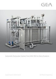
UHT plant type I<br />
UHT Plants are the …<br />
… Basis <strong>for</strong> <strong>Aseptic</strong> <strong>Product</strong> Treatme<br />
The decisive factors in the<br />
selection of the appropriate<br />
UHT process (Ultra High Temperature)<br />
<strong>for</strong> thermal product<br />
treatment are the quality of<br />
the product as much as the<br />
safety and efficiency of production.<br />
GEA TDS has longstanding<br />
experience as a<br />
manufacturer of UHT plants<br />
<strong>for</strong> dairy and other liquid<br />
products.<br />
The capacity of UHT plants ranges<br />
from 50–40,000 l/h <strong>for</strong> the treatment<br />
of low and medium-viscosity products.<br />
The UHT plants are also suitable <strong>for</strong><br />
the thermal and aseptic treatment of<br />
products containing fibres and particles.<br />
GEA TDS markets three different<br />
types of UHT plants – depending on<br />
the product to be treated, the product<br />
quality and efficiency:<br />
UHT plant type I<br />
These product treatment plants work<br />
according to the indirect heating principle.<br />
They provide a very high production<br />
safety thanks to the use of tubular<br />
heat exchanger types S and M. This<br />
process technology has proven successful<br />
in practice <strong>for</strong> many years. Due to<br />
optimised flow conditions, the UHT<br />
plants achieve a good product quality<br />
and high efficiency with heat recovery<br />
rates of up to 90 %. In addition, plant<br />
operation is reliable in every respect.
nt<br />
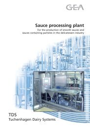
UHT plant type D<br />
The direct heating method used in<br />
these UHT plants offers the advantage<br />
of a very high product quality. The integral<br />
steam injector and a flash cooler<br />
provide very short residence times in<br />
the temperature intensive zones. The<br />
efficiency of this treatment method,<br />
however, is not as high as achieved by<br />
the indirect heating principle. Food<br />
grade steam quality is also required.<br />
UHT plant type P<br />
The UHT plant type P largely uses the<br />
same process technology as the indirect<br />
UHT plant type I. The exception is the<br />
tubular heat exchanger type P, which<br />
makes the indirect heat transfer circuit<br />
between the product to be heated and<br />
that to be cooled dispensable. The advantage<br />
is that this plant type achieves<br />
an even higher efficiency and improved<br />
product quality without the need of<br />
expanding the heat exchange surface.<br />
UHT plant type D<br />
UHT plant type P<br />
2<br />
3
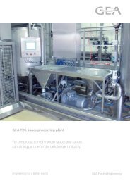
UHT Plants<br />
GEA TDS’ UHT programme<br />
also includes the pilot plant<br />
type L. It is a <strong>com</strong>pact unit<br />
which allows easy transport<br />
to the desired location of use.<br />
This model also uses tubular heat<br />
exchangers. Both UHT methods, i.e.<br />
the indirect and the direct heating<br />
principles, can be applied. The pilot<br />
plant is designed <strong>for</strong> very small capacity<br />
ranges from 50–200 l/h and stands<br />
out by its extraordinary flexibility.<br />
Depending on the specific application,<br />
different units such as heaters, coolers,<br />
heat holding sections and homogenisation<br />
stages can be connected to the<br />
pilot plant by easy-to-handle hose<br />
connections.<br />
The advantages of UHT plants<br />
at one glance:<br />
<strong>Product</strong>ion safety<br />
All UHT plants ensure bacteriological<br />
safety by selecting appropriate heating<br />
parameters, such as temperature and<br />
time, as well as by sterilisation of the<br />
<strong>com</strong>plete UHT process plant prior<br />
to production start. All UHT plants<br />
have in <strong>com</strong>mon effective CIP cleaning<br />
monitored via a conductivity measuring<br />
system.
<strong>Product</strong> quality<br />
The selected UHT technology ensures<br />
that the necessary product related<br />
parameters and variables such as temperature<br />
range, heat holding sections<br />
and homogenisation stages are met so<br />
that the specific UHT process achieves<br />
optimal product quality. In this regard,<br />
special attention is paid to specifically<br />
short product heating and cooling<br />
phases.<br />
Efficiency<br />
Heat recovery, low consumption of<br />
primary energy, low product loss by<br />
short mixing phases as well as short<br />
and efficient CIP cycles, long production<br />
times, low maintenance and<br />
investment costs are the milestones<br />
<strong>for</strong> operational and economic efficiency<br />
of the UHT plant we are always striving<br />
<strong>for</strong>.<br />
Complete pre-assembly<br />
UHT plants are pre-assembled on a<br />
base frame ready <strong>for</strong> connection. The<br />
<strong>com</strong>plete pre-assembly minimises the<br />
assembly work on site. The modular<br />
design of the UHT plants facilitates<br />
later extension or modification work.<br />
UHT pilot plant type L<br />
4<br />
5
Sterile tank units<br />
Sterile Tank Units …<br />
… are the Link between UHT Plant<br />
As an aseptic tank unit, the<br />
sterile tank is the link between<br />
process and packaging.<br />
The sterile tank ensures a consistent<br />
product quality over the entire production<br />
time, since multiple heating of<br />
the product due to production stop or<br />
capacity failure on the filler lines is<br />
ruled out. Another advantage is that<br />
the sterile intermediate storage of the<br />
aseptic product ensures non-stop production<br />
of the filler lines even during<br />
CIP operations carried out on the process<br />
equipment.<br />
Depending on the production volume,<br />
tank capacities from 200 l to 100,000 l<br />
are available.<br />
Sterile tank units allow <strong>for</strong> aseptic,<br />
flexible connections of one or more<br />
process lines and packaging lines, so<br />
that different products can be filled<br />
at the same time without manual<br />
coupling.
and Packaging Line<br />
<strong>Product</strong>ion safety<br />
Sterile tank units from GEA TDS provide<br />
highest possible production safety<br />
by permanent pressure and temperature<br />
control. Monitoring of steam barriers<br />
on all interfaces to the peripheral<br />
equipment of the sterile tank units is<br />
a standard of a sterile tank. Consistent<br />
sterility of the aseptic products is thus<br />
achieved.<br />
Pre-assembly<br />
Sterile air and steam generators are<br />
factory preassembled on a base frame<br />
as a unit ready <strong>for</strong> connection, minimising<br />
assembly work on site. The<br />
standardised design of the pre-assembled<br />
units also prevents any risks<br />
with regard to sterility.<br />
6<br />
7
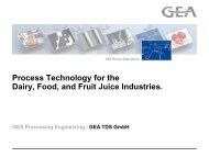
<strong>Product</strong><br />
Water<br />
CIP<br />
Steam<br />
Feed tank<br />
UHT plant<br />
<strong>Product</strong><br />
Principle flow chart <strong>for</strong> in-line separation<br />
Tubular heat exchangers<br />
In-line Separation as an<br />
Integral Part of the UHT Plant<br />
GEA TDS offers the possibility<br />
to <strong>com</strong>bine the traditional UHT<br />
process with an automatic<br />
separator integrated in the<br />
heating process.<br />
Separator<br />
UHT<br />
plant<br />
Thermodynamic<br />
stratified<br />
storage tank<br />
In-line separation avoids double heat<br />
treatment of the product and in this<br />
way achieves high product quality.<br />
The <strong>com</strong>bined function of the thermodynamic<br />
stratified storage tank as well<br />
as the additional, separate heater provided<br />
<strong>for</strong> start and shutdown operations<br />
of the separator allow the continuous<br />
operation of the separator during the<br />
UHT process. By use of thermodynamic<br />
stratified storage tank, UHT heating<br />
can be maintained without interruption<br />
during the automated solids discharge<br />
of the separator.<br />
In-line separation is <strong>com</strong>pletely integrated<br />
in a thermal heating plant and<br />
there<strong>for</strong>e automatically controlled.
Stratified storage tank<br />
Thermodynamic<br />
Stratified Storage Tank<br />
The thermodynamic stratified<br />
storage tank is a buffer tank<br />
between a separator operating<br />
at high temperature and the<br />
process plant.<br />
This thermodynamic stratified<br />
storage tank fulfils two functions<br />
as an intermediate storage facility:<br />
Firstly, it enables continuous integrated<br />
operation of the hot separator in a UHT<br />
or ESL process, even with automated<br />
discharge of solids from the separator.<br />
Secondly, the gases contained in<br />
the product are efficiently removed<br />
through special product guidance.<br />
The product is fed from underneath<br />
into the tank where it is distributed<br />
via a large plate in thin layers over a<br />
large area. The gases contained in<br />
the product are then able to leave the<br />
tank at a corresponding temperature<br />
without the use of a vacuum pump.<br />
A further positive feature is the reduction<br />
of air in the product. As a result<br />
of a lower build-up of deposits in the<br />
heating section, production time of the<br />
process plant is extended and product<br />
quality is increased.<br />
Thanks to the modular design, the<br />
plant can be installed and set into<br />
operation within a very short time.<br />
8<br />
9
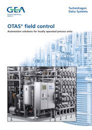
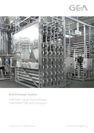
VARITUBE ® M and S, plain and<br />
corrugated inner tubes<br />
VARITUBE ® P<br />
VARITUBE ® HS<br />
VARITUBE ® SK<br />
VARITUBE ®<br />
Tubular Heat Exchange<br />
… the Basic Units <strong>for</strong> <strong>Process</strong> Engin<br />
There are many models of<br />
tubular heat exchangers available<br />
<strong>for</strong> the thermal treatment of<br />
low to medium viscosity fluid<br />
products. They are also suitable<br />
<strong>for</strong> fluids containing particles<br />
or fibres.<br />
The following different types of<br />
tubular heat exchangers are available:<br />
VARITUBE ® M<br />
A tubular heat exchanger where the<br />
product is introduced in one or more<br />
straight internal tubes and is surrounded<br />
by the flow of a heat transfer medium<br />
in a tubular jacket.<br />
VARITUBE ® S<br />
A tubular heat exchanger where the<br />
product is introduced in a straight<br />
internal tube and is surrounded by the<br />
flow of a heat transfer medium in a<br />
tubular jacket.<br />
VARITUBE ® P<br />
A tubular heat exchanger where the<br />
product is introduced in one or more<br />
straight internal tubes and is surrounded<br />
by a counter flow of the same product<br />
in the tubular jacket. In this type of<br />
heat exchanger the internal tubes can<br />
be dismantled <strong>for</strong> inspection purposes.<br />
VARITUBE ® HS<br />
A tubular heat exchanger where the<br />
product is introduced in a number of<br />
internal tubes that are curved through<br />
180°. The heat transfer medium flows<br />
in the surrounding tubular jacket.<br />
When high temperature differences<br />
are present the internal tubes and the<br />
tubular jacket can expand axially, independently<br />
of each other. This prevents<br />
any possible damage caused by differences<br />
in expansion lengths despite the<br />
high temperature differences.<br />
VARITUBE ® SK<br />
A tubular heat exchanger where the<br />
product is introduced in a number of<br />
straight internal tubes and is surrounded<br />
by the flow of a heat transfer medium<br />
in a tubular jacket. To improve the<br />
flow properties <strong>for</strong> products with a<br />
significant particulate and/or fibrous<br />
content, a special cone is fitted to the<br />
tube base plate of the tube bundle.<br />
This effectively causes a concentration<br />
of the product content materials<br />
to impinge against the tube bundle.
s …<br />
eering<br />
Solid design<br />
High resistance to pressure and temperature<br />
is characteristic <strong>for</strong> tubular<br />
heat exchangers. The easy-to-mount<br />
180° pipe bends facilitate the inspection<br />
of the product flow channels.<br />
The straight product flow channels<br />
without flow impeding zones allow<br />
reliable cleaning of the tubular heat<br />
exchangers.<br />
Simple, economical gaskets adapted to<br />
the specific process conditions considerably<br />
reduce maintenance and inspection<br />
costs.<br />
… are suitable as high efficiency,<br />
indirect heating systems <strong>for</strong> the<br />
UHT or ESL process.<br />
All surfaces of the tubular heat<br />
exchangers in contact with the product<br />
are made of material no. 1.4571 (AISI<br />
316 Ti) or better.<br />
The tubular heat exchangers are manufactured<br />
and tested according to the<br />
Pressure Equipment Directive (PED)<br />
97/23 EC.<br />
Application-oriented technology<br />
In accordance with the specific capacity<br />
range as well as the physical properties<br />
of the product, the optimal version can<br />
High Per<strong>for</strong>mance Modules<br />
The system <strong>com</strong>bines the improvements<br />
in the flow and surface properties of<br />
the heat exchanger. By increasing the<br />
product velocities in the tubular heat<br />
exchanger as well as the degree of<br />
turning in the product tubes, a significantly<br />
higher turbulence is achieved in<br />
the product, which results in a faster<br />
production time. This is supported by<br />
electro-polishing of the internal surfaces<br />
of the product tubes. The reduced lam-<br />
inar boundary layer that is <strong>for</strong>med<br />
diminishes the build-up of deposits in<br />
the heat exchanger. As a result of the<br />
increased turbulence, high levels of<br />
sterilisation are achieved more quickly,<br />
even with difficult products. At the<br />
same time, the high per<strong>for</strong>mance module<br />
provides a more effective cleaning<br />
result with a reduced cleaning requirement.<br />
The high per<strong>for</strong>mance module can be<br />
installed in a new facility and also be<br />
integrated into an existing facility. As<br />
a result of the modular design, installation<br />
can take place within a short time.<br />
be selected from the wide range<br />
of tubular heat exchangers. Corrugated<br />
inner tubes, generating increased<br />
turbulences as well as higher surface<br />
qualities are available on request.<br />
Combined modules of one or more<br />
heat exchangers are mounted on a<br />
base frame ready <strong>for</strong> connection.<br />
The modular design facilitates subsequent<br />
extension or modification work.<br />
10<br />
11
Innovative Engineering –<br />
Quality in Line.<br />
To find out more about GEA TDS process<br />
technology, see www.gea-<strong>tds</strong>.<strong>com</strong>.<br />
GEA <strong>Process</strong> Engineering<br />
GEA TDS GmbH<br />
Voss-Straße 11/13 · 31157 Sarstedt · Germany<br />
Phone +49 5066 990-0 · Fax +49 5066 990-163<br />
Am Industriepark 2–10 · 21514 Büchen · Germany<br />
Phone +49 4155 49-2200 · Fax +49 4155 49-2724<br />
Kruppstraße 3 · 48683 Ahaus · Germany<br />
Phone +49 2561 8602-0 · Fax +49 2561 8602-130<br />
www.gea-<strong>tds</strong>.<strong>com</strong><br />
gea<strong>tds</strong>@geagroup.<strong>com</strong><br />
425e-07/11 in<strong>for</strong>m-werbeagentur.de