

Application Compendium - Agilent Technologies
Application Compendium - Agilent Technologies
Application Compendium - Agilent Technologies

Create successful ePaper yourself
Turn your PDF publications into a flip-book with our unique Google optimized e-Paper software.
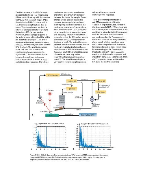
The block scheme of the AM-FM mode<br />
is presented in Figure 11A. The principal<br />
difference of this set-up with the one used<br />
for the AM-AM approach (Figure 4A) is<br />
that the input of LIA-2 is connected to<br />
LIA-1 for measuring the phase data at<br />
vmech. The phase changes are directly<br />
related to changes in the force gradient<br />
that defines AM-FM type studies.<br />
Practically, the AC voltage is applied to<br />
the probe at velec, which should be within<br />
the bandwidth of the LIA-1. The probe<br />
response, at the mixed frequency, vmech<br />
and velec is detected by LIA-2 and used for<br />
KFM feedback. The amplitude sweeps<br />
in the “off” and “on” states of the<br />
electric servo loop are presented in<br />
Figures 11B-C. The electrostatic forces<br />
between the cantilever and sample<br />
cause the cantilever to deflect at velec,<br />
and at twice that frequency. The voltage<br />
A<br />
modulation also causes a modulation<br />
of the force gradient which is greatest<br />
between the tip and the sample. These<br />
changing force gradient causes the<br />
resonant frequency of the cantilever<br />
to shift giving rise to side bands on the<br />
mechanical resonance of the cantilever.<br />
After demodulation by LIA-1, the output<br />
shows modulation at velec and at twice<br />
that frequency. The two forms of KFM<br />
are similar in that the DC bias has a servo<br />
to minimize the velec component from<br />
the input of LIA-2. The main differences<br />
between operation of AM-AM and AM-FM<br />
modes are related with choice of velec,<br />
which in case of AM-FM is limited to low<br />
frequency (say 5kHz), low feedback gains<br />
of the electric servo loop and to<br />
lower AC voltages (usually much less<br />
than 1 V). The use of lower voltages is<br />
very positive remembering the possible<br />
B C<br />
10<br />
voltage influence on sample<br />
surface electric properties.<br />
Figure 11A-C. A block-diagram of the implementation of KFM in <strong>Agilent</strong> 5500 scanning probe microscope<br />
using the MACIII accessory. (B)-(C) Amplitude-vs-frequency sweeps of LIA-2 signal (X-component of<br />
amplitude) with the electric servo loop in the “off” and “on” states, respectively.<br />
There is another implementation of<br />
AM-FM combination in which the<br />
Y-vector of amplitude is used, instead of<br />
the phase signal of LIA-1. When the phase<br />
of LIA-1 is adjusted so the amplitude of the<br />
cantilever is aligned with the X-component<br />
then the tip-sample force interactions<br />
can be observed as the Y-component<br />
variations. The latter naturally reflect the<br />
phase signal, which is calculated using<br />
the X- and Y-component data. Therefore,<br />
for improved signal-to-noise ratio it might<br />
be worth using just the Y-component.<br />
Practically, with LIA-1 set to vmech one<br />
needs to maximize the X-component and<br />
make the Y-component close to zero. Then,<br />
the Y component should be directed to<br />
LIA-2 and the electric servo loop.


