

Application Compendium - Agilent Technologies
Application Compendium - Agilent Technologies
Application Compendium - Agilent Technologies

Create successful ePaper yourself
Turn your PDF publications into a flip-book with our unique Google optimized e-Paper software.
The samples listed as “D” samples<br />
were tested at elevated temperature<br />
over the range from room temperature<br />
to 100 degrees Celsius using the Hot<br />
Stage option that is available with the<br />
Nano Indenter G200. These tests used a<br />
loading time of 1.5 seconds, a hold time<br />
of 1.5 seconds, and an unloading time<br />
of 1.5 seconds. The tests performed on<br />
the hot stage were conducted quickly to<br />
avoid problems associated with thermal<br />
drift of the sample. Surface temperature<br />
of the sample was maintained at the<br />
set temperature within ±0.1 degrees<br />
Celsius. The Hot Stage option allows<br />
elevated temperature testing to be<br />
completed using nanoindentation<br />
over the temperature range from room<br />
temperature to 350°C. While the<br />
sample is maintained at the set point<br />
temperature, an active cooling system<br />
is used to remove waste heat from the<br />
enclosure and an argon gas supply is<br />
used to encapsulate the sample and<br />
reduce corrosion on the surface; the<br />
argon gas supply is primarily used for<br />
testing at temperatures over 200°C.<br />
Scratch Tests<br />
A ramp-load scratch test was used to<br />
conduct five tests on each sample. In a<br />
ramp-load scratch test, a tip is brought<br />
into contact with the sample; then,<br />
the tip is loaded at a constant loading<br />
rate while simultaneously translating<br />
the sample. Prior to and following the<br />
scratch test, a single-line-scan of the<br />
surface topography is completed for<br />
comparing the original surface to the<br />
deformation caused by the scratch test.<br />
Therefore, each scratch test consists<br />
of three steps: a single-line pre-scan of<br />
the area to be scratched, the ramp load<br />
scratch test, and a final scan to evaluate<br />
the residual deformation. Before and<br />
after each step, a pre-profile and a<br />
post-profile, usually equal to 20% of the<br />
scratch length, is performed so that the<br />
software can automatically align the<br />
data in the three steps. The original and<br />
residual single-line scans allow for the<br />
evaluation of deformation mechanisms<br />
and the quantification of deformation.<br />
The scratch process is diagramed in<br />
Figure 2.<br />
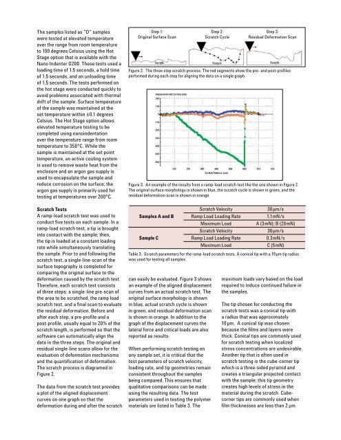
The data from the scratch test provides<br />
a plot of the aligned displacement<br />
curves on one graph so that the<br />
deformation during and after the scratch<br />
Step 1:<br />
Original Surface Scan<br />
can easily be evaluated. Figure 3 shows<br />
an example of the aligned displacement<br />
curves from an actual scratch test. The<br />
original surface morphology is shown<br />
in blue, actual scratch cycle is shown<br />
in green, and residual deformation scan<br />
is shown in orange. In addition to the<br />
graph of the displacement curves the<br />
lateral force and critical loads are also<br />
reported as results.<br />
When performing scratch testing on<br />
any sample set, it is critical that the<br />
test parameters of scratch velocity,<br />
loading rate, and tip geometries remain<br />
consistent throughout the samples<br />
being compared. This ensures that<br />
qualitative comparisons can be made<br />
using the resulting data. The test<br />
parameters used in testing the polymer<br />
materials are listed in Table 3. The<br />
3<br />
Step 2:<br />
Scratch Cycle<br />
Step 3:<br />
Residual Deformation Scan<br />
Figure 2. The three step scratch process. The red segments show the pre- and post-profiles<br />
performed during each step for aligning the data on a single graph.<br />
Figure 3. An example of the results from a ramp-load scratch test like the one shown in Figure 2.<br />
The original surface morphology is shown in blue, the scratch cycle is shown in green, and the<br />
residual deformation scan is shown in orange.<br />
Scratch Velocity 30 µm/s<br />
Samples A and B Ramp Load Loading Rate 1.1mN/s<br />
Maximum Load A (3mN); B (20mN)<br />
Scratch Velocity 30 µm/s<br />
Sample C Ramp Load Loading Rate 0.3 mN/s<br />
Maximum Load C (5mN)<br />
Table 3. Scratch parameters for the ramp-load scratch tests. A conical tip with a 10 µm tip radius<br />
was used for testing all samples.<br />
maximum loads vary based on the load<br />
required to induce continued failure in<br />
the samples.<br />
The tip chosen for conducting the<br />
scratch tests was a conical tip with<br />
a radius that was approximately<br />
10µm. A conical tip was chosen<br />
because the films and layers were<br />
thick. Conical tips are commonly used<br />
for scratch testing when localized<br />
stress concentrations are undesirable.<br />
Another tip that is often used in<br />
scratch testing is the cube-corner tip<br />
which is a three-sided pyramid and<br />
creates a triangular projected contact<br />
with the sample; this tip geometry<br />
creates high levels of stress in the<br />
material during the scratch. Cubecorner<br />
tips are commonly used when<br />
film thicknesses are less than 2 µm.


