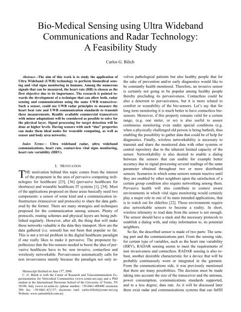
Bio-Medical Sensing using Ultra Wideband Communications and ...
Bio-Medical Sensing using Ultra Wideband Communications and ...
Bio-Medical Sensing using Ultra Wideband Communications and ...

Create successful ePaper yourself
Turn your PDF publications into a flip-book with our unique Google optimized e-Paper software.
Abstract—The aim of this work is to study the application of<br />
<strong>Ultra</strong> <strong>Wideb<strong>and</strong></strong> (UWB) technology to perform biomedical sensing<br />
<strong>and</strong> vital signs monitoring in humans. Among the numerous<br />
signals that can be measured, the heart rate (HR) is chosen as the<br />
first objective due to its importance. The research is pointed towards<br />
the development of a technique that can allow both, radar<br />
sensing <strong>and</strong> communications <strong>using</strong> the same UWB transceiver.<br />
Such a sensor, could use UWB radar principles to measure the<br />
heart beat rate <strong>and</strong> UWB communication st<strong>and</strong>ards to transmit<br />
these measurements. Readily available commercial transceivers<br />
with minor adaptations will be considered as possible to solve for<br />
the physical layer. Signal processing for target detection will be<br />
done at higher levels. Having sensors with such “duo” properties<br />
can make them ideal nodes for wearable computing, as well as<br />
sensor <strong>and</strong> body area networks.<br />
Index Terms— <strong>Ultra</strong> wideb<strong>and</strong> radar, ultra wideb<strong>and</strong><br />
communications, heart rate, contact-less vital signs monitoring,<br />
heart rate variability (HRV).<br />
T<br />
<strong>Bio</strong>-<strong>Medical</strong> <strong>Sensing</strong> <strong>using</strong> <strong>Ultra</strong> <strong>Wideb<strong>and</strong></strong><br />
<strong>Communications</strong> <strong>and</strong> Radar Technology:<br />
A Feasibility Study<br />
I. MOTIVATION<br />
HE motivation behind this topic comes from the interest<br />
of the proponent in the area of pervasive computing technologies<br />
for healthcare [23], [36] (pervasive healthcare for<br />
shortness) <strong>and</strong> wearable healthcare IT systems [1], [34]. Most<br />
of the applications proposed on those areas basically need two<br />
components: a sensor of some kind <strong>and</strong> a communication infrastructure<br />
(transceiver <strong>and</strong> protocols) to share the data gathered<br />
by the former. There are many strategies <strong>and</strong> techniques<br />
proposed for the communication among sensors. Plenty of<br />
protocols, routing schemes <strong>and</strong> physical layers are being published<br />
regularly. However, after all, the thing that will make<br />
these networks valuable is the data they transport. How are the<br />
data gathered (i.e. sensed) has not been that popular so far.<br />
This is not a trivial problem in the digital healthcare paradigm<br />
if one really likes to make it pervasive. The proponent hypothesizes<br />
that the bio-sensors needed to boost the idea of pervasive<br />
healthcare have to be: non invasive, contactless <strong>and</strong><br />
wirelessly networkable. Pervasiveness automatically calls for<br />
non invasiveness mainly because the paradigm not only in-<br />
Manuscript finished on June 15 th , 2006.<br />
C. G. Bilich is with the Center of Research <strong>and</strong> Telecommunication Experimentation<br />
for Networked Communities (www.create-net.org) <strong>and</strong> a PhD<br />
student at the International Doctorate School of the University of Trento, TN<br />
38100, Italy (www.ict.unitn.it). (phone number: +39-0461-408400 extension<br />
309; fax: +39-0461-421157; electronic mail: carlos.bilich@create-net.org<br />
Website: www.carlosbilich.com.ar).<br />
Carlos G. Bilich<br />
volves pathological patients but also healthy people that for<br />
the sake of prevention <strong>and</strong>/or early diagnostics would like to<br />
be constantly health monitored. Therefore, an invasive sensor<br />
is certainly not going to be popular among healthy people<br />
thereby precluding its pervasiveness. Contactless could be<br />
also a deterrent to pervasiveness, but it is more related to<br />
comfort or wearability of the bio-sensors. Let’s say that for<br />
long term monitoring it is much better to have contactless biosensors.<br />
Moreover, if this property remains valid for a certain<br />
range, (e.g. one meter, or so) is also useful to assure<br />
continuous monitoring even under special conditions (e.g.<br />
when a physically challenged old person is being bathed), thus<br />
enabling the possibility to gather data that could be of help for<br />
diagnostics. Finally, wireless networkability is necessary to<br />
transmit <strong>and</strong> share the monitored data with other systems or<br />
central repository due to the inherent limited capacity of the<br />
sensor. Networkability is also desired to enable a dialog<br />
between the sensors that can enable for example better<br />
accuracy due to signal processing several readings of the same<br />
parameter obtained throughout two or more distributed<br />
sensors. Scenarios in which some sensors remain inactive until<br />
they are enabled by other neighbors upon the satisfaction of a<br />
certain group condition also require networking among them.<br />
Pervasive health will also contribute to context aware<br />
environments in which vital signs monitoring would certainly<br />
play a major role in one of its main intended applications, that<br />
is to watch out for elderlies [22]. Those environments require<br />
also networkable sensors to become a reality. In short,<br />
wireless telemetry to read data from the sensor is not enough.<br />
The sensor should have a stack <strong>and</strong> the necessary protocols to<br />
establish a dialog with, <strong>and</strong> relay information to, its potential<br />
neighbors.<br />
So far, the described sensor is made of two parts: The sensing<br />
part <strong>and</strong> the communications part. From the sensing side,<br />
for certain type of variables, such as the heart rate variability<br />
(HRV), RADAR sensing seems to meet the requirements of<br />
non invasiveness <strong>and</strong> contactless. RADAR sensing is also robust,<br />
another desirable characteristic for a device that will be<br />
probably continuously worn or integrated in the garment.<br />
From the communications side, it was previously mentioned<br />
that there are many possibilities. The decision must be made<br />
taking into account the size of the transceiver <strong>and</strong> the antenna,<br />
power consumption, communications st<strong>and</strong>ards supported,<br />
<strong>and</strong> to a less degree, data rate. As it will be discussed later<br />
there exist radar <strong>and</strong> communications systems that can fulfill
the requirements separately. However, to the best of the author<br />
knowledge there is no system that integrates both things<br />
in one device. It would be highly desirable to have a system<br />
that can meet the needs of both systems, that is, perform radar<br />
detection <strong>and</strong> sensing together with communications <strong>using</strong> the<br />
same transceiver.<br />
One technique that satisfies this desire is <strong>Ultra</strong> <strong>Wideb<strong>and</strong></strong><br />
(UWB) technology. Being heavily researched <strong>and</strong> applied for<br />
many years in military radar applications, UWB technology is<br />
making its way towards wireless communications networks<br />
through the st<strong>and</strong>ardization process leading by the IEEE [16],<br />
[17]. There are various reasons why UWB seems to satisfy the<br />
previously stated requirements, but the most important is that:<br />
due to its resolution, it can be used as an accurate radar, <strong>and</strong><br />
due to its resistance to multipath (which is a consequence of<br />
its resolution) it can be used for communications at high<br />
speed; <strong>and</strong> both tasks can be performed <strong>using</strong> the same design<br />
(i.e. same pulse shape, same frequency, transmitted power,<br />
etc.). This is key to the motivation of this idea because it<br />
opens the possibility to the design of biosensors that can be<br />
highly integrated, small <strong>and</strong> power efficient, something that<br />
has been wanted for long in this research community.<br />
There is another motivation that is not at all banal. As it was<br />
mentioned before the IEEE is progressing on the st<strong>and</strong>ardization<br />
of UWB communications. However as it usually happens,<br />
companies start to commercialize early versions of the technology<br />
in order to gain some market thus influencing the decision.<br />
Beyond these strategies, from the point of view of this<br />
article, having early UWB communications chipsets enable<br />
the possibility to leave for a moment the simulation<br />
environment to experiment with real systems. This is a fact of<br />
inestimable value to validate the theory <strong>and</strong> perform<br />
affordable tests “in-vivo” that could, at the end, pave the way<br />
towards tangible devices that can provide useful results in real<br />
scenarios.<br />
Finally, there is also an altruistic motivation due to the<br />
many applications that such a device could have to enhance<br />
the wellness of the population. An UWB radar/ communications<br />
sensor alike, would be small, thus easily portable. This<br />
in turn would enable proactive home monitoring of vital signs,<br />
which in an aging population could decrease the cost of<br />
healthcare by moving some amount of eligible patients from<br />
hospital to home. Considering the potential saving this is not a<br />
minor thing [19], [14]. The medical applications are numerous<br />
<strong>and</strong> have been devised as early as in 1996 [26]. Apart from<br />
what has already been described, an UWB radar can be used<br />
to measure cardiac volume; respiration movement detection<br />
<strong>and</strong> diagnostic (e.g. prevention of Sudden Infant Death Syndrome<br />
–SIDS–, <strong>and</strong> Obstructive Sleep Apnea Syndrome –<br />
OSAS–); internal blood pressure that can be indirectly derived<br />
from a measurement of arterial pulsation; pregnancy monitoring;<br />
in general almost any object of adequate size can be<br />
monitored (e.g. vocal cords; vessels; bowels; lung; chest;<br />
bladder; fetus; etc.)<br />
From all the applications listed before this proposal focuses<br />
specially in the Heart Rate Variability (HRV). The HRV, as<br />
an indicator for the cardiovascular autonomous nerve system,<br />
codifies the activity of the peripheral <strong>and</strong> central parasympathetic<br />
<strong>and</strong> sympathetic nervous system. For example, through<br />
the usage of brain imaging methods it has been confirmed that<br />
the high frequency power component contained in the HRV<br />
signal, reflects activities seen in some areas of the brain<br />
critical to the allocation of resources during stress, such as the<br />
medial pre-frontal cortex [20]. As such, the evaluation of<br />
HRV is a way to monitor non-invasively neural activity linked<br />
to the capacity to st<strong>and</strong> stressful situations (e.g. threats).<br />
Therefore, in this case HRV reveals its utility in the<br />
assessment of human performance due to its link with actual<br />
cognitive activity. Other studies have identified HRV as an<br />
effective diagnostic <strong>and</strong> prognostic marker for a variety of<br />
health conditions [30], [13]. In general, the link between<br />
respiration patterns <strong>and</strong> emotional <strong>and</strong> mental state has been<br />
recognized for many years [5], [2]. It can be said that having<br />
the possibility to obtain a long history of HRV measurements<br />
can provide physicians with a new variable to consider in their<br />
diagnostics, similar to what happen with today’s chemical<br />
blood analysis, x-ray radiology, <strong>and</strong> alike. It can be also good<br />
for physiopathological research, as it can be used to prove<br />
some theories <strong>and</strong> open new research paths [21].<br />
The rest of the article is organized as follows: Section 2,<br />
surveys the state of the art. Section 3, provides a rough calculation<br />
of the range that could be theoretically obtained <strong>using</strong><br />
an already available UWB RF transceiver. And finally section<br />
4, describes a possible research approach.<br />
II. SURVEY OF THE STATE OF THE ART<br />
The idea described here mix knowledge taken from two research<br />
areas: RADAR <strong>and</strong> wireless communications. Both<br />
areas use electromagnetic waves to achieve their respective<br />
objectives; however the techniques <strong>and</strong> the theory behind<br />
them can be rather dissimilar at times or name the same things<br />
differently in other cases. Therefore, to be consequent with the<br />
scope of this section, the state of the art of both technologies<br />
will be briefly surveyed. The signal to be measured as well as<br />
the operating regulations constitute other related areas that are<br />
also reviewed for the sake of completeness.<br />
A. UWB impulse radars as biomedical sensors<br />
UWB impulse radars are characterized by very wide b<strong>and</strong>widths<br />
<strong>and</strong> a corresponding fine range resolution. UWB radar<br />
technology has been heavily researched mainly by the U.S.<br />
Army, <strong>and</strong> unfortunately much of this work remains<br />
classified. As the study of the UWB propagation phenomena<br />
progressed throughout the years, several claims were rose<br />
about its amazing potential performance benefits especially<br />
for applications such as terrain profiling through foliage or<br />
camouflage, <strong>and</strong> ground penetration to find buried objects; as<br />
well as enhanced capabilities for counter-stealth or low<br />
probability of interception. So promising were those claims<br />
that in 1990 the U.S. Defense Advance Research Projects<br />
Agency (DARPA) commissioned a study to verify them [9].
At that time, the assessment panel concluded that there was no<br />
credible evidence of unique phenomenological capabilities<br />
related to the claims <strong>and</strong> that it did not believe impulse radar<br />
offers a major new military capability nor correspondingly did<br />
it present the threat of a serious technological surprise. It also<br />
added that either conventional wideb<strong>and</strong> (i.e. non-impulse) or<br />
UWB impulse radars could accomplish the same tasks.<br />
Having said that, UWB impulse radar was simple another<br />
technique to approach problems whose solution was already<br />
known <strong>using</strong> other conventional methods. However, the report<br />
emphasized several times that UWB impulse radar might<br />
present substantial advantages in terms of implementation<br />
cost, size or weight especially for short range applications,<br />
<strong>and</strong> these are exactly the properties that this proposal aims to<br />
exploit.<br />
The idea of monitoring physiologic functions in humans<br />
<strong>using</strong> radars started as early as the 1970s (see [33] <strong>and</strong> the<br />
references therein), but further development was hindered by<br />
the cumbersome <strong>and</strong> costly technology of those years. Microwave<br />
radiation safety concerns was another deterrent. Particularly<br />
regarding UWB technology, an UWB radar application<br />
was first described on a paper in a scientific journal in 1998<br />
[15]. There are also several U.S. patents describing its medical<br />
applications. One of the most cited is the one awarded to<br />
Thomas McEwan [27]. The patent is the result of a work done<br />
at the U. S. Lawrence Livermore National Laboratory (LLNL)<br />
[26]. This publication describes promising medical applications<br />
already mentioned in the previous section, <strong>and</strong> it emphasizes<br />
that the average emission level used (≈1µW) is about<br />
three orders of magnitude lower than most international st<strong>and</strong>ards<br />
for continuous human exposure to microwaves making<br />
the device medically harmless. Aside from LLNL, UWB radar<br />
applications in medicine are being or were studied at University<br />
of California Davis (breath, speech); University of California<br />
Berkeley (speech); University of Iowa (speech). Experimental<br />
prototypes were built <strong>and</strong> tested by Ossberger et al.<br />
[31]; Immoreev et al.[18]; Michahelles et al. [28]; <strong>and</strong> Tor<br />
Vergata University of Rome [33]. Particularly this last reference<br />
is very interesting because it may be the first attempt to<br />
seriously model the phenomena, that is, the scattering of UWB<br />
pulses along the path to the heart while the other references<br />
focused mostly on the signal processing once the reading is<br />
obtained in a more or less empirical manner. However to the<br />
best of the author knowledge no commercial device has ever<br />
hit the market.<br />
B. UWB communications<br />
UWB communications has been receiving a lot of publicity<br />
recently because it is regarded as the future technology for<br />
high data rate <strong>and</strong> short range transmission. Since late 2001<br />
the IEEE Wireless Personal Area Networks Group started a<br />
st<strong>and</strong>ardization process [16], [17], that has received a lot of<br />
contributions <strong>and</strong> research resources from academy <strong>and</strong><br />
private companies. There are a lot of papers covering almost<br />
every aspect as well as very good textbooks <strong>and</strong> reviews [6],<br />
[24].<br />
Moreover, the first applications providing a complete chip-<br />
set solution (i.e. Medium Access Controller, Baseb<strong>and</strong> controller<br />
<strong>and</strong> RF transceiver) are hitting the market [10], [11].<br />
This proves that, even though the technology has not yet been<br />
st<strong>and</strong>ardized, is maturing quickly. This is good because for the<br />
sake of this work the UWB communication technology is considered<br />
as being given, that is, ready to use. The task is then to<br />
discover an efficient way to use the same commercial transceiver<br />
<strong>and</strong> st<strong>and</strong>ard protocols to perform radar sensing but<br />
without disrupting the communications in order to get an usable<br />
sensor that can also participate in a network.<br />
C. Radar <strong>and</strong> communications integration<br />
The integration of radar sensing together with communications<br />
equipment has been used in aerospace satellites <strong>and</strong> exploration<br />
vehicles mainly in order to save space, since some<br />
components such as the transmitter, receiver <strong>and</strong> antenna can<br />
perform well in either role. Reference [3] is a good example of<br />
such integration, where the combination provides the radar<br />
eyes <strong>and</strong> the communications the ears <strong>and</strong> voice for the<br />
NASA’s Space Shuttle Orbiter. This ku b<strong>and</strong> system<br />
integrates a wideb<strong>and</strong> two-way data system <strong>and</strong> a frequencyhopping,<br />
low repetition rate, pulse-Doppler radar. The system<br />
has two modes: In the radar mode, it measures range, velocity,<br />
angle <strong>and</strong> angle rate. In the communications mode, it receives<br />
<strong>and</strong> demodulates the spread spectrum forward <strong>and</strong> return link<br />
with the ground station. Frequency diversity is used to<br />
integrate both systems assigning 13.775 GHz for<br />
communications <strong>and</strong> a b<strong>and</strong> of 13.8~14.0 GHz for radar. Such<br />
closeness in frequency is required to avoid retuning the low<br />
noise amplifiers when switching from the radar to the<br />
communications mode.<br />
There were also other proposals aimed to integrate radar<br />
<strong>and</strong> communications for automotive systems. Researchers at<br />
Mazda Motor Corp. presented a vehicle-to-vehicle communication<br />
<strong>and</strong> ranging system based on the ranging capabilities of<br />
spread spectrum (SS) named “SS communication radar” [29],<br />
[35]. A car equipped with this system can range others not<br />
equipped by measuring the start of the returned PN code as<br />
given by the correlation peak. In case the other car has a similar<br />
system they can exchange information. The range resolution<br />
was about 1 meter <strong>and</strong> the data rate about 12.6 kbps, either<br />
values fairly low for the application envisioned by this<br />
article.<br />
With the same application in mind DaimlerChrysler AG<br />
along with the Technische Universität München [38],<br />
designed a system in which the communication b<strong>and</strong> is<br />
located in the first null of the radar pulse spectrum. This could<br />
be done because the frequency b<strong>and</strong> of the communication<br />
transceiver is small compared to the pulse spectrum (i.e. 1.5<br />
vs. 250 MHz). Because the b<strong>and</strong>s overlapped, the same RF<br />
front-end could be used thus decreasing the cost. The pulse<br />
radar was designed to allow simultaneous sensing <strong>and</strong><br />
communications reaching a range of 40 meters for the former<br />
<strong>and</strong> 200 meters for the latter.<br />
For the army, multifunction RF systems can reduce military<br />
costs while minimize radar cross section <strong>and</strong> probability of<br />
detection thus enabling them to work simultaneously with tol-
erable co-site interference. This has motivated Roberton et al.<br />
at UCLA to develop a Chirped Spread-Spectrum Integrated<br />
Radar <strong>and</strong> Communication [32], allowing the elements of the<br />
antenna array to simultaneously transmit <strong>and</strong> receive communications<br />
<strong>and</strong> radar data. During transmission radar pulses are<br />
combined (overlapped) with communications bits. The quasiorthogonality<br />
between “up-chirps” (frequency increasing with<br />
time) <strong>and</strong> “down-chirps” (frequency decreasing with time), is<br />
used to solve for self-jamming. The radar <strong>and</strong> communications<br />
signals occupy the same frequency b<strong>and</strong>, but have opposite<br />
polarity in their respective frequency sweeps.<br />
Finally, from the medical side researchers at Bell Labs,<br />
have proposed a system in which a commercial 2.4GHz<br />
cordless phone together with a simple add-on module is used<br />
to detect human respiration <strong>and</strong> heart activity [25]. The<br />
module puts together an antenna <strong>and</strong> a mixer to receive direct<br />
<strong>and</strong> back-scattered transmissions from the wireless terminal.<br />
Then it uses the principles of Doppler radar to output a signal<br />
proportional to the motion of the person’s heart <strong>and</strong> chest.<br />
However, to the best of this author’s knowledge no integrated<br />
UWB radar/communication system has been published<br />
yet.<br />
D. Regulations<br />
<strong>Communications</strong> systems that are not respectful of current<br />
regulation can be conceived for the sake of research, however<br />
medical monitoring systems in that condition can be harmful<br />
for people’s health <strong>and</strong> will be of no practical interest. Therefore<br />
there is no other choice but to design something that can<br />
be compatible with actual legislation on electromagnetic emission.<br />
In the field of UWB transmission, regulations are recent<br />
in some countries, <strong>and</strong> still missing in others. That immaturity<br />
calls for a revision of its current state. However, for the sake<br />
of brevity the legislation on UWB communications systems<br />
can be consulted on reference [6] <strong>and</strong> references therein. Only<br />
the medical side of it will be described here.<br />
Currently, the most widely known emission masks for<br />
UWB radio are those issued by the FCC in the U.S. [8]. The<br />
FCC’s regulation established three types of UWB devices<br />
based on their potential to cause interference: 1) imaging<br />
systems including Ground Penetrating Radars (GPRs); wallthrough-wall<br />
surveillance, <strong>and</strong> medical imaging devices, 2)<br />
vehicular radar systems, <strong>and</strong> 3) communications <strong>and</strong><br />
measurement systems. The following comment reflects the<br />
youth of this legislation: “This combination of technical<br />
st<strong>and</strong>ards <strong>and</strong> operational restrictions will ensure that UWB<br />
devices coexist with the authorized radio services without the<br />
risk of harmful interference while we gain experience with this<br />
new technology. In the meantime, we plan to expedite<br />
enforcement action for any UWB products found to be in<br />
violation of the rules we are adopting <strong>and</strong> will act promptly to<br />
eliminate any reported harmful interference from UWB<br />
devices.” [8]. According to this, chances are it will change.<br />
The regulation mentions that medical systems must be operated<br />
in the frequency b<strong>and</strong> 3.1~10.6 GHz. <strong>and</strong> describes it as a<br />
system that “may be used for a variety of health applications<br />
to ‘see’ inside the body of a person or animal”. And it specifi-<br />
cally adds: “Operation must be at the direction of, or under<br />
the supervision of, a licensed care practitioner.” Regarding<br />
communications, such as high-speed home <strong>and</strong> business networking<br />
devices, it also sets the range of frequencies between<br />
3.1~10.6 GHz, thus allowing simultaneous operation of radar<br />
sensing <strong>and</strong> communications in the same b<strong>and</strong>, which is in the<br />
interest of this application. In that range, the average power<br />
spectral density should not go over -41.3 dBm/MHz in either<br />
operation mode. This is equivalent to approximately 0.55 mW<br />
over 7.5 GHz range. As it will be shown later, commercial<br />
UWB devices rarely use more than 2 GHz b<strong>and</strong>width, which<br />
under the rules mentioned above gives approximately 0.16<br />
mW that, according to [33] <strong>and</strong> the references therein, is intrinsically<br />
safe for humans even under chronic monitoring<br />
conditions.<br />
Finally, in March 2005 the FCC granted a waiver which basically<br />
enables the usage of direct sequence UWB as gated<br />
system to achieve a power spreading effect similar to frequency<br />
hopping. This means gated UWB systems can also<br />
transmit at higher power levels <strong>and</strong> then sit quiet, as long as<br />
they still meet the same limits for average power density during<br />
the certification testing. The effect of this waiver is twofold:<br />
from the communication point of view it translates into<br />
higher data rates, <strong>and</strong> from the radar side it allows better<br />
range.<br />
E. Heart Rate Variability<br />
The interest in the Heart Rate Variability (HRV) as a non<br />
invasive diagnostic indicator has been constantly high through<br />
the last 30 years. A very recent number of the IEEE transactions<br />
on biomedical engineering included a special issue on<br />
the latest advances in HRV signal processing <strong>and</strong><br />
interpretation which constitutes a good example of its<br />
contemporaneity [4]. The state of the art about the study of<br />
this physiological variable has been reviewed there <strong>and</strong> the<br />
references therein. Particularly, the usage of HRV has been<br />
proposed as a useful signal in a number of medical areas as<br />
diverse as: cardiovascular modeling; sleep studies; detection<br />
of apnea episodes in preterm infants; classification of<br />
pregnancy disorders; vaso-vagal syncope; bedside monitoring<br />
<strong>and</strong> early diagnosis of sepsis in premature infants in neonatal<br />
intensive care units; autonomic dysfunction <strong>and</strong> related<br />
pathologies, just to mention a few.<br />
Among the myriad of applications envisioned for HRV<br />
measurements, the proponent is particularly interesting in two:<br />
Aging detection <strong>and</strong> identification of arrhythmias in postmyocardial<br />
infarcted patients. In an aging society where the<br />
healthcare costs are trying to be cut by moving eligible<br />
patients from hospital to home, it is important to have<br />
instruments that can monitor ambulatory patients at home.<br />
Autonomic aging detection is important when dealing with<br />
neurodegenerative diseases like Alzheimer <strong>and</strong> Parkinson.<br />
The heart rate dynamics (e.g. HRV) give clues on the aging<br />
evolution of the elder. This in turn, can feed a context<br />
sensitive system which could then adjust the level of support<br />
that the elder requires to continue living alone (e.g. check the<br />
status of appliances more frequently, increase the number of
vocal reminders, etc.), <strong>and</strong>/or send adequate warnings to their<br />
relatives <strong>and</strong> physicians. Regarding postmyocardial infarcted<br />
patients, pervasive HRV monitoring can be used to early<br />
detect fatal ventricular arrhythmias which are one of the main<br />
causes of death in survivors of acute myocardial infarction.<br />
These are applications that could clearly contribute to the well<br />
being of the society.<br />
III. FEASIBILITY STUDY<br />
This section aims to test, in a very roughly <strong>and</strong> approximated<br />
way, if the power available from one commercial UWB<br />
communication system is enough to perform radar sensing at a<br />
reasonable range. For the sake of brevity, the analysis is done<br />
in the far field. However, the distances being envisioned (i.e.<br />
between 15 cm <strong>and</strong> 1 m) are rather short with respect to λ.<br />
Therefore, only a full wave analysis could give a more reliable<br />
estimate of the phenomena. Another thing that is not being<br />
considered is the fact that an UWB antenna will perform differently<br />
in free space than at the interface with the tissue.<br />
A. Power budget of a monostatic radar based on a<br />
commercial UWB communications transceiver<br />
As UWB communications technology matures, chipsets<br />
will start hitting the market. One such example comes from<br />
Motorola’s Freescale Semiconductor which provides an UWB<br />
transceiver as a part of its XS110 chipset for UWB communications<br />
[10]. This work intends to check if this transceiver “as<br />
is” could be used as radar for HR sensing.<br />
The datasheet of the MC270113 UWB RF transceiver<br />
specifies:<br />
• Transmit output power: P t = − 8 [dBm]<br />
• Center frequency: f = 4.<br />
104 [GHz]<br />
• RF frequency range: 3. 1 ≤ f ≤ 5.<br />
1 [GHz]<br />
• B<strong>and</strong>width: B = 2 [GHz]<br />
The FCC’s rules limits the indoor PSD to the values<br />
showed in TABLE I, where the measured b<strong>and</strong>width<br />
is mb = 1 [MHz] . Thus, for the RF frequency range being<br />
considered, the maximum allowed power spectral density is<br />
PSD = −41.<br />
3 [dBm/MHz] . Having a b<strong>and</strong>width of<br />
B = 2 [GHz] , the effective isotropic radiated power is limited<br />
to:<br />
EIRP = PSD ⋅ B<br />
EIRP | dB = PSD [dBm/MHz] + B [dBMHz]<br />
EIRP | = − 41.<br />
3 + 33.<br />
01 = −8.<br />
29 [dBm]<br />
dB<br />
It can be seen that the transmitted output power P t of the<br />
Freescale’s transceiver is approximately equal to FCC’s<br />
maximum allowed EIRP for the frequency range. This leaves<br />
no room for transmitting antenna gain G t , since<br />
EIRP = Pt<br />
⋅Gt<br />
. Therefore, as it is the usual practice in UWB<br />
communications systems, it is chosen an isotropic antenna<br />
with G t = 0 [dBi] .<br />
Given that, the transmitter power density uniformly<br />
distributed at a distance R from the source is<br />
TABLE I<br />
AVERAGE POWER LIMITS SET BY THE FCC IN THE<br />
U.S. FOR INDOR UWB DEVICES [6]<br />
Frequency [MHz] EIRPmb [dBm]<br />
0–960 -41.3<br />
960–1610 -75.3<br />
1610–1990 -53.3<br />
1990–3100 -51.3<br />
3100–10600 -41.3<br />
Above 10600 -51.3<br />
Pt<br />
⋅Gt<br />
P∆<br />
=<br />
2<br />
4πR <strong>and</strong> the fraction intercepted by the target is<br />
Pt<br />
⋅Gt<br />
Pi<br />
= ⋅σ<br />
2<br />
4πR where σ is the radar cross-section (RCS) of the target.<br />
The estimation of σ requires special care, but for the sake<br />
of this approximate power budget, the following is assumed:<br />
“The heart is spherical <strong>and</strong> it behaves as an isotropic<br />
radiator sending back a spherical wave with the same<br />
polarization as the transmitted signal.”<br />
B. RCS components<br />
Radar cross-section is made up of three components: the<br />
area of the target, its reflectivity at the polarization of the<br />
radar’s receiver antenna, <strong>and</strong> the antenna-like “gain” of the<br />
target [7].<br />
[m ]<br />
2 PRefl(tgt)<br />
σ = Atgt ⋅ Γtgt<br />
⋅Gtgt<br />
; Γ tgt =<br />
PImpg(tgt)<br />
where:<br />
A tgt = The projected area of the target as viewed from the<br />
radar<br />
Γtgt = The reflectivity of the target at the polarization of the<br />
radar<br />
G tgt = The antenna-like “gain” of the target in the direction<br />
of the radar<br />
P = The power reflected by the target (in all directions)<br />
Refl(tgt)<br />
P Impg(tgt) = The illuminating power impinging on the target<br />
(within its projected area)<br />
The heart, in the adult, measures about 12 cm in length, 8~9<br />
cm in breadth at the broadest part, <strong>and</strong> 6 cm in thickness [12].<br />
Thus from the assumption made before, the target can be considered<br />
as a sphere of 12 cm diameter.<br />
c<br />
Since the wavelength λ = = 0.<br />
073[m]<br />
is not strictly much<br />
f<br />
shorter than the circumference 2 πa = 2π<br />
⋅0.<br />
06 = 0.<br />
377 [m] (≈<br />
5 times bigger => not much greater); the area cannot be taken<br />
as the optical cross-section [7].
The<br />
circumference<br />
2πa<br />
= ≅ 5 which according to Fig. 1<br />
wavelength λ<br />
belongs to the resonance region <strong>and</strong> thus<br />
[m ]<br />
2<br />
Atgt<br />
2<br />
= 0.<br />
9 ⇒ A = 0.<br />
9⋅<br />
π ⋅0.<br />
06 = 0.<br />
01<br />
2<br />
tgt<br />
πa<br />
Fig. 1. Sphere RCS versus frequency [7].<br />
As for Γ tgt , there exists a measurable difference in reflection<br />
magnitude between the heart muscle <strong>and</strong> the blood it<br />
pushes into the vascular tree, thus following the approach in<br />
[27] (i.e. one dimensional analogy to propagation along a<br />
transmission line, similar to time domain reflectometry<br />
(TDR)), one gets:<br />
Y −1<br />
Z heart<br />
Γtgt<br />
= where Y = <strong>and</strong> Z heart , Zblood<br />
are the<br />
Y + 1<br />
Zblood<br />
propagation impedances of the heart muscle <strong>and</strong> the blood for<br />
the center frequency f .<br />
Reference [27] gives ε r = 40 <strong>and</strong> ε = 60<br />
muscle<br />
r without<br />
blood<br />
mentioning the frequency, but since the pulse utilized there<br />
has duration of 200ps, that is, a frequency of 5 GHz, it can be<br />
assumed that ε r <strong>and</strong> ε muscle r where taken at that frequency.<br />
blood<br />
However, this is a point that needs further clarification to be<br />
done in future works.<br />
µ 0<br />
Using these values <strong>and</strong> the fact that Z = [ Ω]<br />
,<br />
ε rε<br />
0<br />
Z heart = 60 [ Ω]<br />
, <strong>and</strong> Zblood = 49 [ Ω]<br />
one gets:<br />
60<br />
−1<br />
Γ<br />
49<br />
tgt = = 0.<br />
1 ⇒ 10%<br />
reflection magnitude between the<br />
60<br />
+ 1<br />
49<br />
presence <strong>and</strong> absence of heart muscle, probably measured at<br />
5GHz whereas the intended system operates at approximately<br />
4GHz, this introduces an error that must be accounted in<br />
further refinements of this power budget.<br />
Finally, the worst case of G tgt = 1 is assumed.<br />
Computing the RCS with these values gives:<br />
[m ]<br />
2<br />
σ = 0 . 01⋅<br />
0.<br />
1⋅1<br />
= 0.<br />
001<br />
Therefore the fraction of the effective radiated power intercepted<br />
<strong>and</strong> backscattered by the target of spherical cross-sec-<br />
σ<br />
tion is<br />
2<br />
4πR Some amount of this power will be captured by the<br />
2<br />
⋅λ<br />
receiving aperture =<br />
4π<br />
r G<br />
A e where G r = Gt<br />
= 0 [ dBi]<br />
So far the received power can be recast into a product of<br />
three factors:<br />
⎡ σ ⎤ ⎧ Ae<br />
⎫<br />
Pr<br />
= ( Pt<br />
Gt<br />
) ⋅<br />
⎢ ⎥<br />
⋅<br />
2 ⎨ 2 ⎬<br />
(1)<br />
⎣ 4πR<br />
⎦ ⎩4πR<br />
⎭<br />
where:<br />
( PtG t ) = Effective radiated power ( EIRP ) of the radar<br />
transmission in the direction of the heart. Constringent<br />
to be ≈ -8 [dBm] by the FCC’s regulations for<br />
the given system b<strong>and</strong>width.<br />
⎡ σ ⎤<br />
⎢ ⎥<br />
= Fraction of the effective radiated power intercepted<br />
2<br />
⎣4πR<br />
⎦<br />
<strong>and</strong> backscattered by the heart assuming it has a<br />
spherical cross-section.<br />
⎧ Ae ⎫<br />
⎨ ⎬ = Fraction of the resulting scattered power captured<br />
2<br />
⎩4πR<br />
⎭<br />
by the receiving aperture.<br />
The expression (1) is basically the radar equation assuming<br />
a lossless propagation medium.<br />
C. Propagation loss<br />
For the sake of this approximation two values can be referenced.<br />
Staderini [33] putted together a model (Fig. 2) with<br />
data obtained from the Visible Human Project <strong>and</strong> the<br />
Gabriel’s data book of dielectric properties of tissues. This<br />
model shows a 20 dB round trip loss for the signal to reach the<br />
heart <strong>and</strong> come back (aside from the loss due to reflectivity<br />
which in this work is modeled by Γtgt = 0.<br />
1 equivalent to<br />
10dB loss). The critic to this model is that it has been done<br />
considering a continuous wave at 1.5GHz which is significantly<br />
lower than the 4.1GHz that is being considered here.<br />
Moreover, the characterization was done <strong>using</strong> a narrowb<strong>and</strong><br />
approach instead of the ultra wide-b<strong>and</strong> dielectric properties<br />
required for this project, <strong>and</strong> it is generally accepted in the<br />
UWB community that UWB signals, due to their ultra-wide<br />
frequency range, are not affected in the same way as equivalent<br />
narrow signals are for the same center frequency.<br />
The other value comes for Ossberger et al. [31] that briefly<br />
mentions that the sum of forward <strong>and</strong> backward attenuation is<br />
about 50 dB along the signal path from the air/skin interface<br />
to the heart at a frequency of 2 GHz. The 25 dB difference between<br />
the two references is may be due to the fact that the latter<br />
is also including A tgt in the calculation. Adding A tgt to<br />
Staderini’s model results in a total round trip loss of<br />
Atgt | dB − 35dB<br />
= −20<br />
− 35 = −55dB<br />
which is similar to<br />
Ossberger’s comment. Thus based on Staderini’s model of<br />
Fig. 2, again for the sake of this power budget, it is assumed a<br />
round trip path loss L = 20 [ dB]
Fig. 2. This figure reproduced from [33] is the Staderini’s model predicting<br />
the attenuation of pulse-echo intensity traveling from the transmitting<br />
antenna to the receiving antenna. Each step accounts for echo at the<br />
boundary. Decreasing of the curve accounts for linear attenuation in the<br />
tissue (imaginary part of reflection coefficient <strong>and</strong> multiple reflections are<br />
ignored).<br />
Accounting for the propagation loss the received signal power<br />
becomes:<br />
⎡ σ ⎤ ⎧ Ae<br />
⎫ 1<br />
Pr<br />
= ( Pt<br />
Gt<br />
) ⋅<br />
⎢<br />
⋅ ⋅<br />
2 ⎨ 2 ⎬<br />
4 R<br />
⎥<br />
(2)<br />
⎣ π ⎦ ⎩4πR<br />
⎭ L<br />
D. The effect of noise<br />
To estimate the maximum range R max beyond where the<br />
heart cannot be sensed, the received signal power P r in (2)<br />
must equate to the minimum receiver sensitivity S min .<br />
According to reference [37] the minimum sensitivity for a system<br />
like the one considered here is -85.5 dBm at 28Mbps.<br />
Rearranging <strong>and</strong> expressing R in terms of other variables:<br />
2<br />
4 Pt<br />
Gt<br />
⎡ σ ⎤ ⎪⎧<br />
1 Grλ<br />
⎪⎫<br />
1<br />
R = ⋅ ⎨ ⎬⋅<br />
S ⎢<br />
⋅ ⋅<br />
min 4 ⎥<br />
⎣ π ⎦ ⎪⎩ 4π<br />
4π<br />
⎪⎭ L<br />
c<br />
since G r = Gt<br />
= 1 ⇒ 0 [ dBi]<br />
<strong>and</strong> λ = one gets:<br />
f<br />
2<br />
1<br />
3<br />
2<br />
64<br />
⎟<br />
min<br />
⎟<br />
⎛ c P ⎞<br />
⎜<br />
t σ<br />
R =<br />
⎜<br />
⋅ ⋅ ⋅<br />
⎝ π S f L ⎠<br />
Given that:<br />
Pt = −8<br />
[dBm]<br />
= 158.<br />
49 [ µ W]<br />
S<br />
min<br />
= −85.<br />
5 [dBm]<br />
= 2.<br />
82 [ pW]<br />
2<br />
σ = 0.<br />
001 [m ]<br />
f = 4 . 104 [GHz]<br />
L = 20 [ dB]<br />
= 100<br />
6 m<br />
c = 299.<br />
79 × 10 [ ]<br />
s<br />
Replacing the values <strong>and</strong> computing: R ≅ 20 [ cm]<br />
Since according to Fig. 2 the heart is approximately 4 cm<br />
under the skin, this means that with this system based on the<br />
freescale’s MC270113 UWB RF transceiver “as is”, that is,<br />
without any modification, one can be able to detect the heart<br />
at approximately 15 cm away from the body which is quite<br />
good for a contact-less sensor with the functions envisioned<br />
here.<br />
As it is, the sensor would benefit from the small size, highly<br />
integrated electronics <strong>and</strong> antenna of the st<strong>and</strong>ard embodiment<br />
provided from factory. This will in turn make communications<br />
1<br />
4<br />
with peer sensors effortless, freeing the designer of this problem<br />
to concentrate on the signal processing <strong>and</strong> protocol functions<br />
needed to obtain a meaningful reading.<br />
E. Possible improvements to increase range<br />
Aside from the elemental calculation showed before, there<br />
is still room for improvement of range. Here are some<br />
possibilities:<br />
• Transmitted power: It was mentioned that the indoor maximum<br />
transmitted power is regulated by FCC UWB masks<br />
approved in 2002 [8]. However under the waiver approved<br />
on March 10, 2005, gated UWB systems can also transmit<br />
at higher power levels <strong>and</strong> then sit quiet, as long as they<br />
still meet the same limits for average power density. Gated<br />
is exactly the way in which this radar will work, thus the<br />
waiver open the possibility to an increase in transmitted<br />
power.<br />
• Antenna Gain: Here it was assumed an isotropic unity gain<br />
transmitting/receiving antenna. This can also be manipulated<br />
to increase range as long as the EIRP is kept under<br />
the FCC limits. Care must be taken with directivity since<br />
this could affect the communication capabilities sensor<br />
with neighbor nodes.<br />
• Data rate: Receiver sensitivity S min is directly<br />
proportional to the required SNR for a given data rate. The<br />
previous range was obtained assuming 28 Mbps rate which<br />
is quite fast either for radar sensing <strong>and</strong> data transmission.<br />
SNR requirements can be lowered <strong>and</strong> thus S min<br />
improved by lowering the data rate. This possibility is<br />
suggested in [11] where it is mentioned that<br />
“synchronization can be performed at a reduced data rate<br />
to increase the probability of acquisition in poor signal-tonoise<br />
ratio environments”. This characteristic of the<br />
communication system can be useful to increase the range<br />
of the radar system.<br />
• Frequency range: As can be seen from TABLE I the range<br />
0 ≤ f ≤ 960 [MHz] also has a power spectral density of<br />
− 41.<br />
3 [dBm/MHz] . This is a very interesting range because<br />
a signal with low frequency components suffers less<br />
attenuation when penetrating human tissues, thus improving<br />
range. Maybe without much effort <strong>and</strong> by just introducing<br />
minor modifications (i.e. dynamically adjusting external<br />
circuits like the clock <strong>and</strong> output filters) the chipset<br />
can be made to work in these frequencies for radar<br />
sensing, clocking it back to 4 GHz for communications.<br />
• Heart model: The assumption used to model the heart is<br />
clearly too coarse. An accurate model could probably offer<br />
better results hopefully increasing the range. To start with,<br />
a model similar to Fig. 2 has to be calculated but considering<br />
the frequencies <strong>and</strong> the UWB characteristics of the radiated<br />
signals considered here. The reflection must be recomputed<br />
with the right impedances measured at the right<br />
frequencies.<br />
In conclusion, the actual range is quite good but it would be<br />
nice to increase it to about 1 m because this would provide<br />
more flexibility to the application. Tweaking the parameters<br />
mentioned before seems to be an affordable <strong>and</strong> easy way to
approximate to that objective. The solution is definitely not<br />
impossible because there were some prototypes that achieved<br />
sensing distances of 3 m [27]; 1 m behind a 20 cm thick brick<br />
wall or 5 m without obstacles [31]; <strong>and</strong> 0.1~3 m in [18].<br />
However there are big differences between these systems <strong>and</strong><br />
the one proposed here: First, they are not modulated, that is,<br />
they radiate the pulse in baseb<strong>and</strong>, therefore including low<br />
frequency components that are less attenuated in tissues.<br />
Second, they use directional antennas, typically some kind of<br />
horn with gain > 1. Third, they were not thought to respect the<br />
FCC rules, thus they do not respect emission levels of the<br />
FCC <strong>and</strong> cannot be commercialized. Four, <strong>and</strong> the most<br />
important for the sake of this work, they do not provide<br />
communications capabilities, therefore they cannot be part of<br />
a sensor network, nor they increase detection accuracy by<br />
processing multiple signals coming from nearby peer<br />
neighbors.<br />
IV. RESEARCH APPROACH & CONCLUSION<br />
The research could start by refining the radar propagation<br />
model used before to adjust it to the frequencies <strong>and</strong> to the<br />
ultra wide b<strong>and</strong>width signals that will be utilized here.<br />
The next step is to work on the determination of the radar<br />
cross section or scattering model of the heart. Previously, for<br />
the sake of simplicity, the heart was considered a spherical<br />
isotropic scatterer in the far field. Such approximation is<br />
clearly too coarse <strong>and</strong> has to be revised in order to clearly<br />
know what will be measured. In other words, as it was reviewed,<br />
it is rather easy to aim an UWB radar to the thorax<br />
<strong>and</strong> obtain a signal which is somehow related to heart motion.<br />
However it is not at all easy to know what is actually being<br />
measured, <strong>and</strong> this calls for an accurate model of the object<br />
being monitored.<br />
Another point to investigate is how the performance of a<br />
communication antenna is affected when placed at the interface<br />
with tissue. With the help of the refined propagation <strong>and</strong><br />
the antenna model, the power budget will be recomputed to<br />
asses the feasibility <strong>and</strong>/or the possible alternatives.<br />
Then follows a study of what are the modifications needed<br />
to perform radar sensing with commercially available UWB<br />
communications devices such as [10] <strong>and</strong> [11]. Also, due to<br />
the availability in the market of UWB USB evaluation kits, it<br />
would be nice to conclude this part with the construction of a<br />
prototype to perform several in vivo tests in order to finally<br />
assess the feasibility.<br />
Once the signals are available either from simulation or<br />
from the prototype the work could continue studying the<br />
signal processing techniques necessary to successfully recover<br />
the HRV.<br />
Finally, in the case a working prototype could have been<br />
built, it would be nice to demonstrate the communication capabilities<br />
of the sensor, showing the transmission of HRV<br />
measurements to nearby neighbors or to a central repository as<br />
a proof of the networkability.<br />
[1]<br />
REFERENCES<br />
Binkley, P.F.; “Predicting the potential of wearable technology”; IEEE<br />
engineering in medicine <strong>and</strong> biology magazine; may/june 2003.<br />
[2] Boiten, F.; Frijda, N. H.; <strong>and</strong> Wientjes, C.J.E.; “Emotions <strong>and</strong><br />
Respiratory Patterns: Review <strong>and</strong> Critical Analysis,” International<br />
Journal of Psychophysiology, 17, pp. 103-128; 1994.<br />
[3] Cager, R.; LaFlame, D.; Parode, L.; “Orbiter Ku-B<strong>and</strong> Integrated Radar<br />
<strong>and</strong> <strong>Communications</strong> Subsystem”; <strong>Communications</strong>, IEEE Transactions<br />
on; Vol. 26, Issue 11, Part 2, pp. 1604 – 1619; Nov 1978.<br />
[4] Cerutti, S.; Goldberger, A.L.; Yamamoto, Y.; “Recent Advances in<br />
Heart Rate Variability Signal Processing <strong>and</strong> Interpretation”; IEEE<br />
Transactions on <strong>Bio</strong>medical Engineering; vol. 53, Issue 1, pp. 1 – 3;<br />
Jan. 2006.<br />
[5] Clausen, J.; “Respiration Movement in Normal, Neurotic, <strong>and</strong> Psychotic<br />
Subjects”; Facta Psychiamka Et Neurologica: Supplementum 68, 1951.<br />
[6] Di Benedetto, M.-G., Giancola, G.; “Underst<strong>and</strong>ing <strong>Ultra</strong> Wide B<strong>and</strong><br />
Radio Fundamentals”; Prentice Hall PTR; Upper Saddel River, NJ,<br />
USA; 2004.<br />
[7] Edde, Byron.; “RADAR: Principles, technology, applications”; Prentice<br />
Hall; 1995.<br />
[8] Federal <strong>Communications</strong> Commission; “Revision of Part 15 of the<br />
Commission’s Rules Regarding <strong>Ultra</strong>-<strong>Wideb<strong>and</strong></strong> Transmission Systems”;<br />
ET Docket 98-153; Washington, D.C., U.S.A; April 22, 2002.<br />
[9] Fowler, C.; Entzminger, J.; Corum, J.; “Assessment of ultra-wideb<strong>and</strong><br />
(UWB) technology”; Aerospace <strong>and</strong> Electronic Systems Magazine,<br />
IEEE, Vol. 5, Issue 11, pp. 45 – 49; Nov. 1990.<br />
[10] Freescale Semiconductor; “MC270113 <strong>Ultra</strong>-<strong>Wideb<strong>and</strong></strong> RF<br />
Transceiver”; MC270113/D Rev. 1.6, 10/2004.<br />
[11] Freescale Semiconductor; “MC270123 <strong>Ultra</strong>-<strong>Wideb<strong>and</strong></strong> Baseb<strong>and</strong><br />
Controller”; MC270123/D Rev. 2.1, 10/2004.<br />
[12] Gray, Henry; “Anatomy of the Human Body”. Philadelphia: Lea &<br />
Febiger, 1918; Bartleby.com, 2000. www.bartleby.com/107/. May 2000<br />
by Bartleby.com<br />
[13] Hilton MF; Bates RA; Godfrey KR; et al.; “Evaluation of Frequency <strong>and</strong><br />
Time-Frequency Spectral Analysis of Heart Rate Variability as a<br />
Diagnostic Marker of the Sleep Apnea Syndrome,” Med. <strong>Bio</strong>l. Eng.<br />
Comput., 37, (6), pp. 760-769; Nov. 1999.<br />
[14] Hoffman, C.; Rice, D.; Sung, H.; “Persons with chronic conditions: their<br />
prevalence <strong>and</strong> costs,” Journal of the American <strong>Medical</strong> Association,<br />
vol. 276, pp. 1473- 1479, Nov. 13, 1996.<br />
[15] Holzrichter, J.F., Burnett, G.C.; Ng LC; Lea, W.A.; “Speech articulator<br />
measurements <strong>using</strong> low power EM-wave sensors”; The Journal of the<br />
Acoustical Society of America; 103(1):622-5; Jan. 1998.<br />
[16] IEEE 802.15 WPAN High Rate Alternative PHY Task Group 3a<br />
(TG3a); http://www.ieee802.org/15/pub/TG3a.html<br />
[17] IEEE 802.15 WPAN Low Rate Alternative PHY Task Group 4a (TG4a);<br />
http://www.ieee802.org/15/pub/TG4a.html<br />
[18] Immoreev, I.Y.; Samkov, S.; Teh-Ho Tao; “Short-distance ultra<br />
wideb<strong>and</strong> radars”; Aerospace <strong>and</strong> Electronic Systems Magazine, IEEE,<br />
Volume 20, Issue 6, pp. 9 – 14; June 2005.<br />
[19] Intel Corporation; “Digital Home Technologies for Aging in Place”;<br />
Available online:<br />
http://www.intel.com/research/print/overview_digital_home.pdf;<br />
2004.<br />
Feb.<br />
[20] Jovanov, E.; O'Donnel, A.; Morgan, A.; Priddy, B.; Hormigo, R.;<br />
“Prolonged telemetric monitoring of heart rate variability <strong>using</strong> wire-less<br />
intelligent sensors <strong>and</strong> a mobile gateway”; EMBSBMES Conference,<br />
2002. Proceedings of the Second Joint; Vol. 3, pp. 1875 - 1876 vol.3;<br />
23-26 Oct. 2002.<br />
[21] Jovanov, E.; O'Donnell Lords, A.; Raskovic, D.; Cox, P.G.; Adhami, R.;<br />
Andrasik, F.; “Stress monitoring <strong>using</strong> a distributed wireless intelligent<br />
sensor system”; Engineering in Medicine <strong>and</strong> <strong>Bio</strong>logy Magazine, IEEE<br />
Vol. 22, Issue 3, pp. 49 – 55; May-June 2003.<br />
[22] Korhonen, I.; Parkka, J.; Van Gils, M.; “Health monitoring in the home<br />
of the future”, IEEE engineering in medicine <strong>and</strong> biology magazine;<br />
May/June 2003.<br />
[23] Korhonen, Ilkka; Bardram, Jakob E.; “Guest editorial introduction to the<br />
special section on pervasive healthcare”; IEEE transactions on<br />
information technology in biomedicine, vol. 8, No., Sept. 2004.<br />
[24] Liuqing Yang; Giannakis, G.B.; “<strong>Ultra</strong>-wideb<strong>and</strong> communications: an<br />
idea whose time has come” Signal Processing Magazine, IEEE, vol. 21,<br />
Issue 6, pp. 26 – 54, Nov. 2004.
[25] Lubecke, V.; Boric-Lubecke, O.; Beck, E.; “A compact low-cost add-on<br />
module for Doppler radar sensing of vital signs <strong>using</strong> a wireless<br />
communications terminal”; Microwave Symposium Digest, 2002 IEEE<br />
MTT-S International; Vol. 3, pp. 1767 – 17; 2-7 June 2002.<br />
[26] McEwan, T.; Azevedo, S.; “Micropower Impulse Radar”; Science &<br />
Technology Review; Lawrence Livermore National Laboratory, US;<br />
Jan./Feb. 1996; Available online:<br />
http://www.llnl.gov/str/pdfs/01_96.2.pdf.<br />
[27] McEwan, Thomas E.; “Body monitoring <strong>and</strong> imaging apparatus <strong>and</strong><br />
method”; United States Patent 5,766,208; June 16, 1998.<br />
[28] Michahelles, Florian; Wicki, Ramon; Schiele, Bernt; “Less Contact:<br />
Heart rate detection without even touching the user”; In Proc. 8th IEEE<br />
International Symposium on Wearable Computers, Arlington, USA<br />
2004.<br />
[29] Mizui, K.; Uchida, M.; Nakagawa, M.; “Vehicle-to-vehicle<br />
communication <strong>and</strong> ranging system <strong>using</strong> spread spectrum technique<br />
(Proposal of Boomerang Transmission System)”; Vehicular Technology<br />
Conference, 1993 IEEE 43rd; pp. 335 – 338; 18-20 May 1993.<br />
[30] Nunes Amaral, L. A.; Goldberger,A.L.; Ivanov, P. Ch.; Stanley, H. E.;<br />
“Scale Independent Measures <strong>and</strong> Pathologic Cardiac Dynam-ics,”<br />
Physical Review Letters, Vol. 81, No. 11, Sep. 1998.<br />
[31] Ossberger, G. Buchegger, T. Schimback, E. Stelzer, A. Weigel, R;<br />
“Non-invasive respiratory movement detection <strong>and</strong> monitoring of hidden<br />
humans <strong>using</strong> ultra wideb<strong>and</strong> pulse radar”; Linz Center of Mechatronics<br />
GmbH, Austria; <strong>Ultra</strong> <strong>Wideb<strong>and</strong></strong> Systems, 2004. Joint with Conference<br />
on <strong>Ultra</strong>wideb<strong>and</strong> Systems <strong>and</strong> Technologies. Joint UWBST &<br />
IWUWBS. 2004 International Workshop on. Publication Date 18-21 May<br />
2004; On page(s) 395- 399.<br />
[32] Roberton, M.; Brown, E.R.; “Integrated radar <strong>and</strong> communications based<br />
on chirped spread-spectrum techniques”; Microwave Symposium Digest,<br />
2003 IEEE MTT-S International; Vol. 1, pp. 611 - 614 vol.1; 8-13 June<br />
2003.<br />
[33] Staderini, E.M.; “UWB radars in medicine”; Aerospace <strong>and</strong> Electronic<br />
Systems Magazine, IEEE, Volume 17, Issue 1, Jan. 2002 Page(s)13 –<br />
18.<br />
[34] Tröster, G.; “The Agenda of Wearable Healthcare.” IMIA Yearbook of<br />
<strong>Medical</strong> Informatics 2005: Ubiquitous Health Care Systems; Stuttgart:<br />
Schattauer; p.125-138; 2004.<br />
[35] Uchida, M.; Kagawa, Y.; Okuno, A.; “A vehicle-to-vehicle<br />
communication <strong>and</strong> ranging system based on spread spectrum technique-<br />
SS communication radar”; Vehicle Navigation <strong>and</strong> Information Systems<br />
Conference, 1994. Proceedings., 1994; pp. 169 – 174; 31 Aug.~2 Sept.<br />
1994.<br />
[36] Varshney, U.; “Pervasive healthcare”; Computer vol. 36, Issue 12, pp.<br />
138 – 140; Dec. 2003.<br />
[37] Welborn, M., Kohno, R., Mc Laughlin, M.;“DS-UWB Physical Layer<br />
Submission to 802.15 Task Group 3a”; IEEE P802.15 Working Group<br />
for Wireless Personal Area Networks (WPANs); IEEE P802.15-<br />
04/0137r3; July 2004.<br />
[38] Winkler, V.; Detlefsen, J.; Siart, U.; Buchler, J.; Wagner, M.;<br />
“Automotive radar sensor with communication capability”; Wireless<br />
Technology, 2004. 7th European Conference on; pp. 305 – 308; 2004.