MULTICAL® 602 - Kamstrup
MULTICAL® 602 - Kamstrup
MULTICAL® 602 - Kamstrup

Create successful ePaper yourself
Turn your PDF publications into a flip-book with our unique Google optimized e-Paper software.
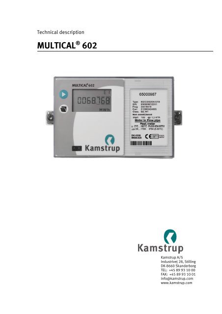
Technical description<br />
MULTICAL ® <strong>602</strong><br />
<strong>Kamstrup</strong> A/S<br />
Industrivej 28, Stilling<br />
DK-8660 Skanderborg<br />
TEL: +45 89 93 10 00<br />
FAX: +45 89 93 10 01<br />
info@kamstrup.com<br />
www.kamstrup.com
TECHNICAL DESCRIPTION MULTICAL ® <strong>602</strong><br />
2 5512-931 GB/10.2012/Rev. F1
TECHNICAL DESCRIPTION MULTICAL ® <strong>602</strong><br />
List of contents<br />
1 General description .......................................................................................................... 6<br />
2 Technical Data .................................................................................................................. 7<br />
2.1 Approved meter data ............................................................................................................................ 7<br />
2.2 Electrical data ....................................................................................................................................... 8<br />
2.3 Mechanical data ................................................................................................................................. 10<br />
2.4 Materials ............................................................................................................................................ 10<br />
2.5 Accuracy ............................................................................................................................................. 10<br />
3 Type overview ................................................................................................................. 11<br />
3.1 Type and programming overview ......................................................................................................... 11<br />
3.2 Type number combination .................................................................................................................. 12<br />
3.3 PROG, A-B-CCC-CCC ............................................................................................................................ 14<br />
3.4 Display coding .................................................................................................................................... 21<br />
3.5 >EE< Configuration of MULTITARIFF ...................................................................................................... 23<br />
3.6 >FF< Input A (VA) - pulse divider, >GG< Input B (VB) - pulse divider ......................................................... 25<br />
3.7 Configuration of pulse outputs in the top module ................................................................................ 26<br />
3.8 >MN< Configuration of leak limits ......................................................................................................... 26<br />
3.9 >T< Configuration of encryption level .................................................................................................... 26<br />
3.10 Data for configuration ......................................................................................................................... 27<br />
4 Dimentional sketches ..................................................................................................... 28<br />
5 Installation ..................................................................................................................... 29<br />
5.1 Flow pipe and return pipe placing ....................................................................................................... 29<br />
5.2 EMC conditions ................................................................................................................................... 30<br />
5.3 Climatic conditions ............................................................................................................................. 30<br />
5.4 Electric installations ........................................................................................................................... 30<br />
6 Calculator functions ........................................................................................................ 31<br />
6.1 Energy calculation .............................................................................................................................. 31<br />
6.2 Application types ................................................................................................................................ 32<br />
6.3 Calculator with two flow sensors ......................................................................................................... 37<br />
6.4 Combined heat/cooling metering ........................................................................................................ 38<br />
6.5 Flow measurement, V1 and V2 ............................................................................................................ 39<br />
6.6 Power measurement, V1 ..................................................................................................................... 40<br />
6.7 Min. and max. flow and power, V1 ...................................................................................................... 41<br />
6.8 Temperature measurement ................................................................................................................. 42<br />
6.9 Display functions ................................................................................................................................ 44<br />
6.10 Real Time Clock (RTC) .......................................................................................................................... 47<br />
6.11 Info codes .......................................................................................................................................... 48<br />
6.12 Tariff functions ................................................................................................................................... 51<br />
6.13 Data loggers ....................................................................................................................................... 56<br />
5512-931 GB/10.2012/Rev. F1 3
TECHNICAL DESCRIPTION MULTICAL ® <strong>602</strong><br />
6.14 Leak surveillance ............................................................................................................................... 58<br />
6.15 Reset functions .................................................................................................................................. 61<br />
6.16 SMS Commands ................................................................................................................................ 61<br />
6.17 Set-up via the front keys..................................................................................................................... 63<br />
6.18 Reset via the front keys ...................................................................................................................... 65<br />
6.19 Preset the pulse value for V1 and V2 .................................................................................................. 66<br />
7 Flow sensor connection .................................................................................................. 67<br />
7.1 Volume inputs V1 and V2 ................................................................................................................... 67<br />
7.2 Flow sensor with active 24 V pulse output .......................................................................................... 69<br />
7.3 Pulse inputs VA and VB ...................................................................................................................... 72<br />
8 Temperature sensors ...................................................................................................... 74<br />
8.1 Sensor types ...................................................................................................................................... 75<br />
8.2 Cable influence and compensation .................................................................................................... 76<br />
8.3 Pocket sensors .................................................................................................................................. 78<br />
8.4 Pt500 short direct sensor set ............................................................................................................. 79<br />
9 Voltage supply ............................................................................................................... 80<br />
9.1 Integral D-cell lithium battery ............................................................................................................. 80<br />
9.2 Battery lifetimes ................................................................................................................................. 81<br />
9.3 High Power supply module 230 VAC ................................................................................................... 82<br />
9.4 High Power supply module 24 VAC ..................................................................................................... 82<br />
9.5 Supply module 230 VAC ..................................................................................................................... 83<br />
9.6 Supply module 24 VAC ....................................................................................................................... 83<br />
9.7 Exchanging the supply unit ................................................................................................................ 85<br />
9.8 Mains supply cables .......................................................................................................................... 85<br />
9.9 Back-up of data during power down ................................................................................................... 86<br />
9.10 Danish regulations for connection of mains operated meters .............................................................. 86<br />
10 Plug-in modules .......................................................................................................... 87<br />
10.1 Top modules ...................................................................................................................................... 87<br />
10.2 Base modules .................................................................................................................................... 93<br />
10.3 Retrofitting modules ........................................................................................................................ 102<br />
11 Data communication .................................................................................................. 103<br />
11.1 MULTICAL � <strong>602</strong> data protocol .......................................................................................................... 103<br />
11.2 MULTICAL ® <strong>602</strong> communication paths ............................................................................................. 105<br />
11.3 Optical eye....................................................................................................................................... 105<br />
12 Calibration and verification ....................................................................................... 106<br />
12.1 High-resolution energy reading ........................................................................................................ 106<br />
12.2 High-resolution volume for test ........................................................................................................ 107<br />
12.3 Verification adapter ......................................................................................................................... 108<br />
12.4 True energy calculation .................................................................................................................... 109<br />
4 5512-931 GB/10.2012/Rev. F1
TECHNICAL DESCRIPTION MULTICAL ® <strong>602</strong><br />
13 METERTOOL for MULTICAL � <strong>602</strong> ................................................................................. 110<br />
13.1 Introduction ...................................................................................................................................... 110<br />
13.2 METERTOOL MULTICAL ® <strong>602</strong> .............................................................................................................. 111<br />
13.3 Verification with METERTOOL MULTICAL � <strong>602</strong> .................................................................................... 115<br />
13.4 LogView MULTICAL � <strong>602</strong> ................................................................................................................... 118<br />
14 Approvals .................................................................................................................. 120<br />
14.1 CE marking ....................................................................................................................................... 120<br />
14.2 Measuring instrument directive ......................................................................................................... 120<br />
15 Trouble-shooting ....................................................................................................... 122<br />
16 Disposal .................................................................................................................... 123<br />
17 Documents ................................................................................................................ 124<br />
18 Appendix A - MULTICAL � <strong>602</strong> vs. previous meters ...................................................... 125<br />
5512-931 GB/10.2012/Rev. F1 5
TECHNICAL DESCRIPTION MULTICAL ® <strong>602</strong><br />
1 General description<br />
MULTICAL ® <strong>602</strong> is a thermal energy meter with many applications. In addition to being a precise and reliable heat<br />
meter for battery or mains operation, MULTICAL ® <strong>602</strong> is also used for:<br />
���Cooling measurement in water-based systems<br />
���Bifunctional heat/cooling measurements in separate registers<br />
���Leak surveillance of hot and cold-water installations<br />
���Power and flow limiter with valve control<br />
���Data logger<br />
���Data communication<br />
���Energy measurement in open systems<br />
In designing the MULTICAL ® <strong>602</strong> we have attached great importance to flexibility via programmable functions and<br />
plug-in modules (see chapter 10) in both the calculator top as well as in the base unit to ensure optimal use in a<br />
large number of applications. In addition, the construction ensures that already installed MULTICAL ® <strong>602</strong> meters<br />
can be updated via the PC program METERTOOL.<br />
This technical description is prepared to give utility managers, meter electricians, consulting engineers and<br />
distributors the possibility of utilizing all functions available in the MULTICAL ® <strong>602</strong>. Furthermore, the description<br />
is made for laboratories for the testing and verification process.<br />
6 5512-931 GB/10.2012/Rev. F1
TECHNICAL DESCRIPTION MULTICAL ® <strong>602</strong><br />
2 Technical Data<br />
2.1 Approved meter data<br />
Standard EN 1434:2007, prEN 1434:2009 and OIML R75:2002<br />
EU directives Measuring Instrument Directive, Low Voltage Directive,<br />
Electromagnetic Compatibity Directive<br />
Heat meter approval DK-0200-MI004-020<br />
Temperature range �: 2�C…180�C<br />
Differential range ��: 3 K…170 K<br />
Cooling meter<br />
Temperature range �: 2�C…50�C<br />
Differential range ��: 3 K…40 K<br />
The stated minimum temperatures<br />
apply to the type approval only.<br />
The meter has no cut-off for low<br />
temperature and thus measures as low<br />
temperatures as<br />
0.01�C and 0.01 K.<br />
Accuracy EC � (0.5 + �� min/��) %<br />
Temperature sensors -Type <strong>602</strong>-A Pt100 – EN 60 751, 2-wire connection<br />
-Type <strong>602</strong>-B and <strong>602</strong>-D Pt500 – EN 60 751, 4-wire connection<br />
-Type <strong>602</strong>-C Pt500 – EN 60 751, 2-wire connection<br />
Compatible flow sensor types -ULTRAFLOW �<br />
-Electronic meters with an active 24 V pulse output<br />
-Mechanical meters with an electronic pick-up unit<br />
-Mechanical meters with a Reed switch<br />
Flow sensor sizes �kWh� qp 0.6 m 3 /h…15 m 3 /h<br />
�MWh� qp 0.6 m 3 /h…1500 m 3 /h<br />
�GJ� qp 0.6 m 3 /h…3000 m 3 /h<br />
EN 1434 designation Environmental class A and C<br />
MID designation Mechanical environment: Class M1<br />
Electromagnetic environment: Class E1 and E2<br />
5…55°C, non condensing, closed location (indoor installation)<br />
5512-931 GB/10.2012/Rev. F1 7
TECHNICAL DESCRIPTION MULTICAL ® <strong>602</strong><br />
2.2 Electrical data<br />
Calculator data<br />
Typical accuracy Calculator: EC � (0.15 + 2/��) % Sensor set: ET � (0.4 + 4/��) %<br />
Display LCD – 7 (8) digits with a digit height of 7.6 mm<br />
Resolution 9999.999 – 99999.99 – 999999.9 – 9999999<br />
Energy units MWh – kWh – GJ – Gcal<br />
Data logger (EEPROM) Standard: 1392 hours, 460 days, 36 months, 15 years, 50 info codes<br />
Option: Data loggers with programmable interval<br />
Clock/calendar<br />
Clock, calendar, compensation for leap years, target date, Real time clock<br />
with battery back-up<br />
Data communication KMP protocol with CRC16 used for optical communication and for top and<br />
base modules<br />
Power in temperature<br />
sensors<br />
� 10 �W RMS<br />
Supply voltage 3.6 VDC ± 0.1 VDC<br />
Battery 3.65 VDC, D-cell lithium<br />
Stand-by current � 15 �A excluding flow sensor<br />
Replacement interval<br />
- Mounted on the wall 12+1 years @ tBAT� 30°C<br />
- Mounted on the flow sensor 10 years @ tBAT� 40°C<br />
The replacement interval is reduced when using data modules, frequent data<br />
communication and high ambient temperature. See chapter 9.2.<br />
Mains supply<br />
230 VAC +15/-30%, 50/60 Hz<br />
24 VAC ±50%, 50/60 Hz<br />
Insulation voltage 4 kV<br />
Power supply � 1W<br />
Back-up supply Integral super-cap eliminates operational disturbances due to short-term<br />
power cuts (Power supply modules type <strong>602</strong>-0000-7 and type <strong>602</strong>-0000-8<br />
only)<br />
EMC data Meets prEN 1434-4:2009 class C (MID class E2)<br />
Temperature measurement<br />
<strong>602</strong>-A<br />
2-W Pt100<br />
<strong>602</strong>-B/D<br />
4-W Pt500<br />
<strong>602</strong>-C<br />
2-W Pt500<br />
T1 T2 T3 T4<br />
Measuring range 0.00…185.00�C 0.00…185.00�C 0.00…185.00�C N/A<br />
Preset range 0.01…180.00�C 0.01…180.00�C 0.01…180.00�C 0.01…180.00�C<br />
Measuring range 0.00…185.00�C 0.00…185.00�C N/A N/A<br />
Preset range 0.01…180.00�C 0.01…180.00�C N/A 0.01…180.00�C<br />
Measuring range 0.00…185.00�C 0.00…185.00�C 0.00…185.00�C N/A<br />
Preset range 0.01…180.00�C 0.01…180.00�C 0.01…180.00�C 0.01…180.00�C<br />
Max. cable lengths Pt100, 2-wire Pt500, 2-wire Pt500, 4-wire<br />
2 x 0.25 mm 2 : 2.5 m<br />
2 x 0.50 mm 2 2 x 0.25 mm<br />
: 5 m<br />
2 : 10 m<br />
2 x 0.50 mm 2 4 x 0.25 mm<br />
: 20 m<br />
2 : 100 m<br />
-<br />
8 5512-931 GB/10.2012/Rev. F1
TECHNICAL DESCRIPTION MULTICAL ® <strong>602</strong><br />
Flow measuring V1 and<br />
V2<br />
ULTRAFLOW �<br />
V1: 9-10-11 and V2: 9-69-11<br />
Reed switches<br />
V1: 10-11 and V2: 69-11<br />
24 V active pulses<br />
V1: 10B-11B and V2: 69B-79B<br />
EN 1434 pulse class IC IB (IA)<br />
Pulse input 680 k� pull-up for 3.6 V 680 k� pull-up for 3.6 V 12 mA at 24 V<br />
Pulse ON � 0.4 V in � 0.5 msec. � 0.4 V in � 100 msec. � 4 V in � 3 msec.<br />
Pulse OFF � 2.5 V in � 10 msec. � 2.5 V in � 100 msec. � 12 V in � 10 msec.<br />
Pulse frequency � 128 Hz � 1 Hz � 128 Hz<br />
Integration frequency � 1 Hz � 1 Hz � 1 Hz<br />
Electrical isolation No No 2 kV<br />
Max. cable length 10 m 25 m 100 m<br />
Pulse inputs without bounce damping:<br />
Pulse inputs VA and VB<br />
VA: 65-66 and VB: 67-68<br />
Water meter connection<br />
FF(VA) and GG(VB) = 71…90<br />
Electricity meter connection<br />
FF(VA) and GG(VB) = 50…60<br />
Pulse input 680 k� pull-up for 3.6 V 680 k� pull-up for 3.6 V<br />
Pulse ON � 0.4 V in � 30 msec. � 0.4 V in � 30 msec.<br />
Pulse OFF � 2.5 V in � 100 msec. � 2.5 V in � 100 msec.<br />
Pulse frequency � 1 Hz � 3 Hz<br />
Electrical isolation No No<br />
Max. cable length 25 m 25 m<br />
Requirements to external<br />
contact<br />
Leakage current at function open � 1 �A<br />
Pulse inputs with bounce damping:<br />
Pulse inputs VA and VB<br />
VA: 65-66 and VB: 67-68<br />
Water meter connection<br />
FF(VA) and GG(VB) = 01…40<br />
Pulse input 680 k� pull-up for 3.6 V<br />
Pulse ON � 0.4 V i � 200 ms.<br />
Pulse OFF � 2.5 V i � 500 ms.<br />
Pulse frequency � 1 Hz<br />
Electrical isolation None<br />
Max. Cable length 25 m<br />
Requirements to external<br />
contact<br />
Leakage current at function open � 1 �A<br />
Pulse outputs CE and CV<br />
- via top module<br />
67-0B<br />
<strong>602</strong>-0C<br />
Type Opto FET Open collector (OB)<br />
External voltage 5…48 VDC/AC 5…30 VDC<br />
Current 1…50 mA 1…10 mA<br />
Residual voltage RON ≤ 40 � UCE ≈ 1 V at 10 mA<br />
Electrical isolation 2 kV 2 kV<br />
Max. cable length 25 m 25 m<br />
Pulse length Optional 32 msec. or 100 msec.<br />
5512-931 GB/10.2012/Rev. F1 9
TECHNICAL DESCRIPTION MULTICAL ® <strong>602</strong><br />
2.3 Mechanical data<br />
Environmental class Meets EN 1434 class A and C<br />
Ambient temperature 5…55°C non condensing, closed location (indoor installation)<br />
Protection class IP54<br />
Storage temperature -20…60°C (drained meter)<br />
Weight 0.4 kg excluding sensors and flow sensor<br />
Connection cables ø3.5…6 mm<br />
Supply cable<br />
2.4 Materials<br />
ø5…10 mm<br />
Top cover PC<br />
Base unit ABS with TPE packings (thermoplastic elastomer)<br />
Print box ABS<br />
Wall brackets PC + 30% glass<br />
2.5 Accuracy<br />
Figure 1. MULTICAL ® <strong>602</strong> typical accuracy compared with EN 1434.<br />
10 5512-931 GB/10.2012/Rev. F1
TECHNICAL DESCRIPTION MULTICAL ® <strong>602</strong><br />
3 Type overview<br />
MULTICAL ® <strong>602</strong> can be ordered in a countless number of combinations as required by the customer. First the<br />
required hardware is selected in the type overview. Then “Prog”, “Config” and “Data” are selected to suit the<br />
application in question.<br />
The meter is delivered completely configured and ready for use from the factory but it can also be<br />
retrofitted/reconfigured after installation.<br />
Please note that the items marked ”Totalprog” can only be changed when the verification seal is broken. This<br />
requires that the change must be made at an accredited meter laboratory.<br />
New functions and modules for MULTICAL ® <strong>602</strong> are constantly being developed. Please contact <strong>Kamstrup</strong> A/S, if<br />
the described variants do not meet your requirements.<br />
3.1 Type and programming overview<br />
Type number (Total prog.)<br />
<strong>602</strong>-X-X-XX-X-XX-X-XXX<br />
Selection of Pt100/Pt500<br />
calculator, modules, supply,<br />
sensor set, flow sensor and<br />
language on label<br />
PROG (Total prog.)<br />
A-B-CCC-CCC<br />
- Flow pipe/Return pipe<br />
- Energy unit<br />
- Flow meter code<br />
CONFIG (Partial prog.)<br />
DDD-EE-FF-GG-M-N-T<br />
- Display<br />
- Tariff<br />
- Pulse inputs<br />
- Leak sensibility<br />
- Pulse outputs<br />
- AMR Encryption level<br />
DATA (Partial prog.)<br />
- Customer no.<br />
- Target date<br />
- Tariff limits<br />
- Average peak time max./min.<br />
- Date/time<br />
5512-931 GB/10.2012/Rev. F1 11
TECHNICAL DESCRIPTION MULTICAL ® <strong>602</strong><br />
3.2 Type number combination<br />
MULTICAL � <strong>602</strong> Type <strong>602</strong>-<br />
Sensor connection<br />
Pt100 2-wire (T1-T2) A<br />
Pt500 4-wire (T1-T2) B<br />
Pt500 2-wire (T1-T2-T3) C<br />
Pt500 4-wire (T1-T2) w/24 V pulse inputs<br />
Top module<br />
D<br />
No module 0<br />
�Energy calculation + hourly data logger 2) 2<br />
PQ or �t-limiter + hourly data logger 3<br />
Data output + hourly data logger 5<br />
M-Bus 7<br />
�Volume + hourly data logger 2) 9<br />
2 pulse outputs for CE and CV + hourly data logger + scheduler A<br />
RTC + 2 pulse outputs for CE and CV + prog. data logger B<br />
2 Pulse outputs CE and CV<br />
Base module<br />
C<br />
No module 00<br />
Data + pulse inputs 10<br />
M-Bus + pulse inputs 1) 20<br />
Radio Router + pulse inputs 21<br />
Prog. data logger + RTC + 4…20 mA inputs + pulse inputs 22<br />
0/4…20 mA outputs 23<br />
LonWorks + pulse inputs 24<br />
Radio + pulse inputs (internal antenna) 434 or 444 MHz 25<br />
Radio + pulse inputs (external antenna connection) 434 or 444 MHz 26<br />
M-Bus module with alternative registers + pulse inputs 27<br />
M-Bus module with medium data package + pulse inputs 28<br />
M-Bus module with MC-III data package + pulse inputs 29<br />
Wireless M-Bus Mode C1 + pulse inputs 30<br />
Wireless M-Bus Mode C1 Alt. reg. + pulse inputs 35<br />
ZigBee 2.4 GHz int.ant. + pulse inputs 60<br />
Metasys N2 (RS485) + pulse inputs 62<br />
SIOX module (Auto detect Baud rate) 64<br />
BACnet MS/TP + pules inputs 66<br />
GSM/GPRS (GSM6H) Require 80<br />
3G GSM/GPRS module (GSM8H) High- Power 81<br />
Ethernet/IP (IP201)<br />
High Power RadioRouter + pulse inputs<br />
supply<br />
modules<br />
82<br />
84<br />
Supply<br />
No supply 0<br />
Battery, D-cell 2<br />
230 VAC high power isolated SMPS 3<br />
24 VAC high power isolated SMPS 4<br />
230 VAC isolated linear supply 7<br />
24 VAC isolated linear supply 8<br />
Pt500 sensor set<br />
No sensor set 00<br />
Pocket sensor set w/1.5 m cable 0A<br />
Pocket sensor set w/3.0 m cable 0B<br />
Pocket sensor set w/5 m cable 0C<br />
Pocket sensor set w/10 m cable 0D<br />
Short direct sensor set w/1.5 m cable 0F<br />
Short direct sensor set w/3.0 m cable 0G<br />
3 Pocket sensors in sets w/1.5 m cable 0L<br />
3 Short direct sensors in sets w/1.5 m cable Q3<br />
Flow sensor /pick-up unit<br />
Supplied w/1 pcs. ULTRAFLOW � (Please specify type) 1<br />
Supplied w/2 pcs. (identical) ULTRAFLOW � (Please specify type) 2<br />
Prepared for 1 pcs. ULTRAFLOW � (Please specify type) 7<br />
Prepared for 2 pcs. (identical) ULTRAFLOW � (Please specify type) 8<br />
Prepared for meters w/electronic pulse output K<br />
Prepared for meters w/Reed switch output (Both V1 and V2) L<br />
Prepared for meters w/24 V active pulses M<br />
Meter type<br />
Heat meter, (MID module B+D) 2<br />
Heat meter, closed systems 4<br />
Cooling meter 5<br />
Heat/Cooling meter 6<br />
Volume meter, hot water 7<br />
Volume meter, cooling water 8<br />
Energy meter, open systems 9<br />
Country code (language on label etc.) XX<br />
12 5512-931 GB/10.2012/Rev. F1
TECHNICAL DESCRIPTION MULTICAL ® <strong>602</strong><br />
3.2.1 Comments to the Type number survey<br />
When placing orders please state ULTRAFLOW � type numbers separately.<br />
1) See paragraph 10.2 for further details.<br />
2) Requires two identical flow sensors.<br />
3.2.2 Accessories<br />
66-00-200-100 D-cell battery<br />
<strong>602</strong>-0000-4000000 24 VAC high power isolated SMPS<br />
<strong>602</strong>-0000-3000000 230 VAC high power isolated SMPS<br />
<strong>602</strong>-0000-8000000 24 VAC isolated linear supply<br />
<strong>602</strong>-0000-7000000 230 VAC isolated linear supply<br />
66-99-624 Pulse transmitter/divider for <strong>602</strong>-A and <strong>602</strong>-C<br />
66-99-614 4-wire connection PCB with pulse inputs for 24 V active pulses (for <strong>602</strong>-D)<br />
66-99-098 Data cable w/USB plug<br />
66-99-099 Infrared optical reading head w/USB plug<br />
66-99-144 Infrared optical reading head for <strong>Kamstrup</strong>/EVL w/USB plug<br />
66-99-102 Infrared optical reading head w/D-sub 9F<br />
66-99-106 Data cable RS 232, D-sub 9F<br />
66-99-397/-398/-399 Verification unit (used with METERTOOL)<br />
65-56-4x-xxx Temperature sensor set with connection head (2/4-wire)<br />
67-9xxxxxx2xx External Communication Box<br />
66-99-718 METERTOOL for MULTICAL ® <strong>602</strong><br />
66-99-719 METERTOOL LogView for MULTICAL ® <strong>602</strong><br />
Please contact <strong>Kamstrup</strong> A/S for questions concerning further accessories.<br />
5512-931 GB/10.2012/Rev. F1 13
TECHNICAL DESCRIPTION MULTICAL ® <strong>602</strong><br />
3.3 PROG, A-B-CCC-CCC<br />
The legal parameters of the meter are determined by Prog, which can only be changed when the verification seal<br />
is broken. The change must then be made at an accreditated meter laboratory.<br />
The A-code indicates whether the flow sensor (V1) is installed in flow or return pipe. As water has a larger volume<br />
at higher temperatures, the calculator must be adjusted for the current installation type. Wrong programming or<br />
installation results in measuring errors. For further details on placing the flow and return pipe of the flow sensor in<br />
connection with heat and cooling meters, see paragraph 5.1.<br />
The B-code indicates the measuring unit used for the energy register. GJ, kWh or MWh are used most frequently,<br />
whereas Gcal is only used in some countries outside the EEA.<br />
The CCC code indicates the calculator’s adaptation to a concrete flow sensor type, i.e. the calculation speed and<br />
display resolution are optimised to the selected flow sensor type and at the same time the type approval<br />
regulations concerning min. resolution and max. register overflow are met. The CCC codes are divided into several<br />
tables to give a better survey.<br />
CCC(V1) indicates the CCC code of the flow sensor and is connected to flow sensor input V1 on terminal 9-10-11<br />
(or 10B-11B), which in most applications is the flow sensor used for calculating energy.<br />
CCC(V2) indicates the CCC code of an extra flow sensor, if any, to be connected to terminal 9-69-11 (or 69B-79B).<br />
If V2 is not used, CCC(V2) = CCC(V1). In connection with leakage surveillance CCC(V2) = CCC(V1).<br />
Prog. number A - B - CCC (V1) - CCC (V2)<br />
Flow sensor placing:<br />
k-factor<br />
table<br />
- Inlet/Flow pipe (at T1) 3<br />
- Outlet/Return pipe (at T2) 4<br />
Measuring unit, energy<br />
- GJ 2<br />
- kWh 3<br />
- MWh 4<br />
- Gcal 5<br />
Flow sensor coding<br />
(CCC-table)<br />
14 5512-931 GB/10.2012/Rev. F1<br />
CCC CCC
TECHNICAL DESCRIPTION MULTICAL ® <strong>602</strong><br />
3.3.1 CCC-table for MULTICAL � <strong>602</strong><br />
The CCC tables are divided into fast pulse codes (CCC=4XX, 2XX and 1XX) for electronic meters, e.g. ULTRAFLOW ® ,<br />
and slow codes for e.g. reed contacts (CCC=0XX).<br />
CCC= 4XX Electronic meters with fast and bounce-free pulses as well as info codes for ULTRAFLOW ® X4<br />
Max. pulse frequency: 128 Hz<br />
Max. integration frequency: 1 Hz<br />
CCC= 1XX, 2XX Electronic meters with fast and bounce-free pulses<br />
Max. pulse frequency: 128 Hz<br />
Max. integration frequency: 1 Hz<br />
CCC= 0XX Mechanical meters delivering slow pulses with bounce (flow sensor type "L")<br />
Max. pulse frequency: 1 Hz<br />
Max. integration frequency: 1 Hz<br />
Max. integration frequency is 1 Hz for all types. The CCC codes are arranged in a way that qs+20% (or<br />
Qmax+20%) does not exceed the 1 Hz in the integration frequency.<br />
Example: CCC=107 (applies for a qp 1.5 m 3 /h meter) : 1 Hz in the integration frequency is obtained at<br />
q = 3.6 m 3 /h.<br />
EN 1434 makes demands on the resolution and registre size of the energy reading. MULTICAL ® <strong>602</strong> meets these<br />
demands when connected to below flow sensor sizes:<br />
�kWh� qp 0.6 m 3 /h…15 m 3 /h<br />
�MWh� qp 0.6 m 3 /h…1500 m 3 /h<br />
�GJ� qp 0.6 m 3 /h…3000 m 3 /h<br />
3.3.2 CCC codes for mechanical flow sensors with Reed switch<br />
Number of decimals on the display<br />
CCC<br />
no.<br />
Precounter<br />
Flow factor<br />
kWh MWh<br />
Gcal<br />
GJ m³<br />
�ton�<br />
m³/h l/h kW MW l/pulses Pulses/l<br />
Qmax<br />
�m³/h�<br />
Flow<br />
sensor<br />
010 1 921600 1 - 3 3 - 0 1 - 1 1 � 3,0 L<br />
011 1 921600 - 3 2 2 2 - 0 - 10 0.1 1…30 L<br />
012 1 921600 - 2 1 1 1 - - 2 100 0.01 10…300 L<br />
013 1 921600 - 1 0 0 0 - - 1 1000 0.001 100…3000 L<br />
020 4 230400 0 3 2 2 2 - 0 - 2.5 0.4 � 6 L<br />
021 4 230400 - 2 1 1 1 - - 2 25 0.04 3…60 L<br />
022 4 230400 - 1 0 0 0 - - 1 250 0.004 30…600 L<br />
Current flow (l/h or m³/h) reading is calculated on the basis of the measured period between 2 volume pulses<br />
(see paragraph 6.5)<br />
When one of above CCC codes has been selected both CCC (V1) and CCC (V2) must be selected from this table.<br />
Note: Continuous maximum water flow and permanent �� > 75 K may cause overflow in the daily data logger at<br />
CCC=010-011-012-013-150-202-205. With these combinations we recommend you to use Prog. data logger type<br />
67-0B or type 67-00-22.<br />
5512-931 GB/10.2012/Rev. F1 15
TECHNICAL DESCRIPTION MULTICAL ® <strong>602</strong><br />
3.3.3 CCC codes for ULTRAFLOW � II, type 65 54 XXX<br />
CCC<br />
no.<br />
Precounter<br />
Flow<br />
factor<br />
kWh MWh<br />
Gcal<br />
Number of decimals on the display<br />
GJ m³<br />
�ton�<br />
16 5512-931 GB/10.2012/Rev. F1<br />
l/h m³/h kW MW Pulses/l qp<br />
�m³/h�<br />
116 3000 78642 0 3 2 2 0 - 1 - 300 0.6 65 54 A8X<br />
65 54 AAX<br />
119 1000 235926 0 3 2 2 0 - 1 - 100 1.5 65 54 A6X<br />
65 54 A7X<br />
65 54 A1X<br />
65 54 A2X<br />
65 54 A3X<br />
136 500 471852 0 3 2 2 0 - 1 - 50.0 2.5<br />
Type no. Flow<br />
sensor<br />
65 54 A4X<br />
65 54 ADX<br />
151 5000 471852 - 2 1 1 0 - 1 - 50.0 3.5 65 54 B1X<br />
65 54 B7X<br />
137 2500 943704 - 2 1 1 0 - 1 - 25.0 6.0<br />
6.0<br />
10<br />
10<br />
120 1000 2359260 - 2 1 1 0 - 1 - 10.0 15<br />
25<br />
65 54 B2X<br />
65 54 B5X<br />
65 54 BGX<br />
65 54 BHX<br />
65 54 B4X<br />
65 54 B8X<br />
1-2-7-8<br />
1-2-7-8<br />
1-2-7-8<br />
1-2-7-8<br />
1-2-7-8<br />
1-2-7-8<br />
158 5000 471852 - 1 0 0 - 2 0 - 5.0 40 65 54 B9X 1-2-7-8<br />
170 2500 943704 - 1 0 0 - 2 - 3 2.5 60 65 54 BAX 1-2-7-8<br />
147 1000 2359260 - 1 0 0 - 2 - 3 1.0 150 65 54 BBX 1-2-7-8<br />
194 400 5898150 - 1 0 0 - 2 - 3 0.4 400 65 54 BCX 1-2-7-8<br />
195 250 9437040 - 1 0 0 - 2 - 3 0.25 1000 65 54 BKX 1-2-7-8<br />
Current flow reading (l/h or m³/h) is calculated on the basis of volume pulses/10 sec. (see paragraph 6.5)
TECHNICAL DESCRIPTION MULTICAL ® <strong>602</strong><br />
3.3.4 CCC codes for ULTRAFLOW � type 65-SRT<br />
CCC<br />
no.<br />
Precounter <br />
Flowfactor<br />
kWh MWh<br />
Gcal<br />
Number of decimals on the display<br />
GJ m³<br />
�ton�<br />
l/h m³/h kW MW Pulses/l qp<br />
�m³/h�<br />
Type no. Flow part<br />
116 3000 78642 0 3 2 2 0 - 1 - 300 0.6 65-X-CAAA-XXX<br />
65-X-CAAD-XXX<br />
119 1000 235926 0 3 2 2 0 - 1 - 100 1.5 65-X-CDAC-XXX<br />
65-X-CDAD-XXX<br />
65-X-CDAE-XXX<br />
65-X-CDAF-XXX<br />
65-X-CDAA-XXX<br />
136 500 471852 0 3 2 2 0 - 1 - 50.0 3.0 65-X-CFAF-XXX<br />
65-X-CFBA-XXX<br />
151 5000 471852 - 2 1 1 0 - 1 - 50.0 3.5 65-X-CGAG-XXX<br />
65-X-CGBB-XXX<br />
137 2500 943704 - 2 1 1 0 - 1 - 25.0 6<br />
6<br />
10<br />
10<br />
65-X-CHAG-XXX<br />
65-X-CHBB-XXX<br />
65-X-C1AJ-XXX<br />
65-X-C1BD-XXX<br />
1-2-7-8-K<br />
1-2-7-8-K-M<br />
1-2-7-8-K-M<br />
1-2-7-8-K-M<br />
1-2-7-8-K-M<br />
178 1500 1572840 - 2 1 1 0 - 1 - 15.0 10 65-X-CJAJ-XXX<br />
65-X-CJBD-XXX<br />
1-2-7-8-K-M<br />
120 1000 2359260 - 2 1 1 0 - 1 - 10.0 15 65-X-CKBE-XXX 1-2-7-8-M<br />
179 600 3932100 - 2 1 1 0 - 1 - 6.0 25 65-X-CLBG-XXX 1-2-7-8-K<br />
120 1000 2359260 - 2 1 1 0 - 1 - 10.0 25 65-X-C2BG-XXX 1-2-7-8-K-M<br />
158 5000 471852 - 1 0 0 - 2 0 - 5.0 40 65-X-CMBH-<br />
XXX<br />
1-2-7-8-K-M<br />
170 2500 943704 - 1 0 0 - 2 - 3 2.5 60 65-X-FABL-XXX<br />
65-X-FACL-XXX<br />
1-2-7-8-K-M<br />
180 1500 1572840 - 1 0 0 - 2 - 3 1.5 100 65-X-FBCL-XXX 1-2-7-8-K<br />
147 1000 2359260 - 1 0 0 - 2 - 3 1.0 150 65-X-FCBN-XXX<br />
65-X-FCCN-XXX<br />
1-2-7-8-K-M<br />
181 600 3932100 - 1 0 0 - 2 - 3 0.6 250 65-X-FDCN-XXX 1-2-7-8-K<br />
191 400 589815 - 1 0 0 - 1 - 2 0.4 400 65-X-FEBN-XXX<br />
65-X-FEBR-XXX<br />
65-X-FECN-XXX<br />
65-X-FECP-XXX<br />
65-X-FECR-XXX<br />
1-2-7-8-K-M<br />
192 250 943704 - 1 0 0 - 1 - 2 0.25 600 65-X-FFCP-XXX 1-2-7-8--KM<br />
600 65-X-FFCR-XXX<br />
1000 65-X-F1BR-XXX<br />
1000 65-X-F1CR-XXX<br />
193 150 1572840 - 1 0 0 - 1 - 2 0.15 1000 65-X-FGBR-XXX 1-2-7-8-K<br />
Current flow reading (l/h or m³/h) is calculated on the basis of volume pulses/10 sec. (see paragraph 6.5)<br />
5512-931 GB/10.2012/Rev. F1 17
TECHNICAL DESCRIPTION MULTICAL ® <strong>602</strong><br />
3.3.5 CCC codes with high resolution for ULTRAFLOW � (for cooling meters etc.)<br />
CCC<br />
no.<br />
Precounter<br />
Flow<br />
factor<br />
kWh MWh<br />
Gcal<br />
Number of decimals on the display<br />
GJ m³<br />
�ton�<br />
18 5512-931 GB/10.2012/Rev. F1<br />
l/h m³/h kW MW Pulses/l qp<br />
�m³/h�<br />
Type no. Flow sensor<br />
184 300 78642 1 - 3 3 0 - 1 - 300 0.6 1-2-7-8<br />
107 100 235926 1 - 3 3 0 - 1 - 100 1.5 1-2-7-8-M<br />
136 500 471852 0 3 2 2 0 - 1 - 50.0 3.5 1-2-7-8-M<br />
138 250 943704 0 3 2 2 0 - 1 - 25.0 6.0<br />
10<br />
1-2-7-8-M<br />
183 150 1572840 0 3 2 2 0 - 1 - 15.0 10 1-2-7-8<br />
185 100 2359260 0 3 2 2 0 - 1 - 10.0 15 1-2-7-8-M<br />
186 500 471852 - 2 1 1 - 2 0 - 5.0 40 1-2-7-8-M<br />
187 250 943704 - 2 1 1 - 2 - 3 2.5 60 1-2-7-8-M<br />
188 150 1572840 - 2 1 1 - 2 - 3 1.5 100 1-2-7-8<br />
189 100 2359260 - 2 1 1 - 2 - 3 1.0 150 1-2-7-8-M<br />
191 400 589815 - 1 0 0 - 1 - 2 0.4 400 1-2-7-8-M<br />
192 250 943704 - 1 0 0 - 1 - 2 0.25 600<br />
1000<br />
1-2-7-8-M<br />
193 150 1572840 - 1 0 0 - 1 - 2 0.15 1000 1-2-7-8<br />
Current flow reading (l/h or m³/h) is calculated on the basis of volume pulses/10 sec. (see paragraph 6.5)<br />
3.3.6 CCC codes for other electronic meters with a passive output<br />
CCC<br />
no.<br />
Precounter<br />
Flow<br />
factor<br />
MWh<br />
Gcal<br />
Number of decimals on the display<br />
GJ m³<br />
�ton�<br />
m³/h kW MW l/pulse Pulses/l Qmax<br />
�m³/h�<br />
Type Flow<br />
sensor<br />
147 1000 2359260 1 0 0 2 - 3 1 - 18...75 SC-18 K-M<br />
148 400 5898150 1 0 0 2 - 3 2.5 - 120…300 SC-120 K-M<br />
149 100 2359260 1 0 0 1 - 2 10 - 450…1200 SC-450 K-M<br />
150 20 11796300 1 0 0 1 - 2 50 - 1800…3000 SC-1800 K-M<br />
175 7500 314568 1 0 0 2 - 3 - 7.5 15…30 DF-15 K-M<br />
176 4500 524280 1 0 0 2 - 3 - 4.5 25…50 DF-25 K-M<br />
177 2500 943704 1 0 0 2 - 3 - 2.5 40…80 DF-40 K-M<br />
CCC<br />
no.<br />
Precounter<br />
Flow<br />
factor<br />
Number of decimals on the display<br />
MWh<br />
Gcal<br />
GJ m³<br />
�ton�<br />
m³/h MW l/pulse Pulse/l Qp range<br />
�m³/h�<br />
Qs<br />
(m³/h)<br />
201 100 235926 2 1 1 1 2 1 1 10…100 75 FUS380<br />
DN50-65<br />
202 40 589815 2 1 1 1 2 2.5 0.4 40…200 240 FUS380<br />
DN80-100<br />
203 400 589815 1 0 0 1 2 2.5 0.4 100…400 500 FUS380<br />
DN125<br />
204 100 235926 1 0 0 0 1 10 0.1 150…1200 1600 FUS380<br />
DN150-250<br />
205 20 1179630 1 0 0 0 1 50 0.02 500…3000 3600 FUS380<br />
DN300-400<br />
Current flow reading (l/h or m³/h) is calculated on the basis of volume pulses/10 pcs. (see paragraph 6.5)<br />
3.3.7 CCC codes for other electronic meters with an active output<br />
Flow sensor with active 24 V pulse output, see paragraph 7.2<br />
Type Flow<br />
sensor<br />
K-M<br />
K-M<br />
K-M<br />
K-M<br />
K-M
TECHNICAL DESCRIPTION MULTICAL ® <strong>602</strong><br />
3.3.8 CCC codes for vane wheel meters with an electronic pick-up unit<br />
CCC<br />
no.<br />
Precounter<br />
Flow<br />
factor<br />
kWh MWh<br />
Gcal<br />
Number of decimals on the display<br />
GJ m³<br />
�ton�<br />
l/h m³/h kW MW Pulses/l qp<br />
�m³/h�<br />
Type Flow<br />
sensor<br />
102 560 421296 0 3 2 2 0 - 1 - 56.0 1.5/2.5 GWF-MT3 K<br />
103 300 786420 0 3 2 2 0 - 1 - 30.0 3.5 GWF-MT3 K<br />
104 2520 936214 - 2 1 1 0 - 1 - 25.2 6 GWF-MT3 K<br />
105 1230 1918098 - 2 1 1 0 - 1 - 12.3 10 GWF-MT3 K<br />
106 1080 2184500 - 2 1 1 0 - 1 - 10.8 15 GWF-MT3 K<br />
108 1403 168158 0 3 2 2 0 - 1 - 140.3 0.6 GWF K<br />
109 957 246527 0 3 2 2 0 - 1 - 95.7 1.0 GWF K<br />
110 646 365211 0 3 2 2 0 - 1 - 64.6 1.5 GWF K<br />
111 404 583975 0 3 2 2 0 - 1 - 40.4 1.5 (2.5) HM (GWF) K<br />
112 502 469972 0 3 2 2 0 - 1 - 50.2 1.5 – 2.5* GWF K<br />
113 2350 1003940 - 2 1 1 0 - 1 - 23.5 3.5 - 6* GWF K<br />
114 712 331357 - 2 1 1 0 - 1 - 7.12 10 - 15* GWF K<br />
115 757 311659 0 3 2 2 0 - 1 - 75.7 1.0* GWF K<br />
116 3000 78642 0 3 2 2 0 - 1 - 300.0 0.6* GWF K<br />
117 269 877048 0 3 2 2 0 - 1 - 26.9 1.5 Brunata K<br />
118 665 354776 0 3 2 2 0 - 1 - 66.5 1.5 Aquastar K<br />
119 1000 235926 0 3 2 2 0 - 1 - 100.0 0.6 HM K<br />
121 294 802469 0 3 2 2 0 - 1 - 29.4 1.5 – 2.5 K<br />
122 1668 141442 0 3 2 2 0 - 1 - 166.8 0.6 HM K<br />
123 864 273063 0 3 2 2 0 - 1 - 86.4 0.75 - 1* HM K<br />
124 522 451966 0 3 2 2 0 - 1 - 52,2 2.5 (1.5*) CG (HM) K<br />
125 607 388675 0 3 2 2 0 - 1 - 60.7 1.5 - 1*<br />
1.5*<br />
HM K<br />
126 420 561729 0 3 2 2 0 - 1 - 42.0 1.0 (2.5*) CG (HM) K<br />
127 2982 791167 - 2 1 1 0 - 1 - 29.82 2.5<br />
3.5*<br />
HM K<br />
128 2424 973292 - 2 1 1 0 - 1 - 24.24 3.5* HM K<br />
129 1854 1272524 - 2 1 1 0 - 1 - 18.54 6* HM K<br />
130 770 3063974 - 2 1 1 0 - 1 - 7.7 10* HM K<br />
131 700 3370371 - 2 1 1 0 - 1 - 7.0 15* HM K<br />
132 365 645665 0 3 2 2 0 - 1 - 36.54 2.5 Wehrle K<br />
133 604 390154 0 3 2 2 0 - 1 - 60.47 1.5 Wehrle K<br />
134 1230 191732 0 3 2 2 0 - 1 - 123.05 0.6 Wehrle K<br />
135 1600 1474538 - 2 1 1 0 - 1 - 16.0 10* HM K<br />
139 256 921586 0 3 2 2 0 - 1 - 25.6 1.5 – 2.5 GWF K<br />
140 1280 1843172 - 2 1 1 0 - 1 - 12.8 3.5 – 5.0 GWF K<br />
141 1140 2069526 - 2 1 1 0 - 1 - 11.4 6 GWF K<br />
142 400 589815 - 2 1 1 - 2 - 3 4 10 GWF K<br />
143 320 737269 - 2 1 1 - 2 - 3 3.2 10 - 15 GWF K<br />
144 1280 1843172 - 1 0 0 - 2 - 3 1.28 25 - 40 GWF K<br />
145 640 3686344 - 1 0 0 - 2 - 3 0.64 60 GWF K<br />
146 128 18431719 - 1 0 0 - 2 - 3 0.128 125 GWF K<br />
152 1194 1975930 - 2 1 1 0 - 1 - 11.94 10 GWF K<br />
153 1014 2326686 - 2 1 1 0 - 1 - 10.14 15 GWF K<br />
156 594 397182 0 3 2 2 0 - 1 - 59.4 1.5 Metron K<br />
157 3764 626796 - 2 1 1 0 - 1 - 37.64 2.5 Metron K<br />
163 1224 192750 0 3 2 2 0 - 1 - 122.4 0.6 – 1.0 GWF/U2 K<br />
164 852 280064 0 3 2 2 0 - 1 - 85.24 1.5 GWF/U2 K<br />
165 599 393735 0 3 2 2 0 - 1 - 59.92 2.5 GWF/U2 K<br />
168 449 5259161 - 2 1 1 0 - 1 - 4.486 15/25 HM/WS K<br />
169 1386 1702208 - 1 0 0 - 2 0 - 1.386 40 HM/WS K<br />
173 500 471852 - 1 0 0 - 1 - 2 0.5 80 Westland K<br />
Current flow reading (l/h or m³/h) is calculated on the basis of volume pulses/10 sec. (see paragraph 6.5)<br />
* Multiple-jet water meter<br />
5512-931 GB/10.2012/Rev. F1 19
TECHNICAL DESCRIPTION MULTICAL ® <strong>602</strong><br />
3.3.9 ULTRAFLOW � X4 CCC-codes<br />
CCC<br />
no.<br />
Precounter<br />
Flow<br />
factor<br />
kWh<br />
MWh<br />
Gcal<br />
Number of decimals on the display<br />
GJ m³<br />
�ton�<br />
l/h m³/h kW MW Pulses/l qp<br />
20 5512-931 GB/10.2012/Rev. F1<br />
�m³/h�<br />
Type Flow<br />
sensor<br />
416 3000 78642 0 3 2 2 0 - 1 - 300 0.6 65-X-CAAA-XXX 1-2-7-8<br />
65-X-CAAD-XXX<br />
65-X-CAAF-XXX<br />
484 300 78642 1 - 3 3 0 - 1 - 300 0.6 1-2-7-8<br />
419 1000 235926 0 3 2 2 0 - 1 - 100 1.5 65-X-CDA1-XXX 1-2-7-8<br />
65-X-CDAA-XXX<br />
65-X-CDAC-XXX<br />
65-X-CDAD-XXX<br />
65-X-CDAE-XXX<br />
65-X-CDAF-XXX<br />
65-X-CDBA-XXX<br />
407 100 235926 1 - 3 3 0 - 1 - 100 1.5 1-2-7-8<br />
498 600 393210 0 3 2 2 0 - 1 - 60 2.5 65-X-CEAF-XXX 1-2-7-8<br />
65-X-CEBA/CECA-XXX<br />
65-X-CEAD-XXX<br />
451 5000 471852 - 2 1 1 0 - 1 - 50 3.5 65-X-CGAG-XXX 1-2-7-8<br />
65-X-CGBB/CGCB-XXX<br />
436 500 471852 0 3 2 2 0 - 1 - 50 3.5 1-2-7-8<br />
437 2500 943704 2 1 1 0 1 25 6 65-X-CHAF-XXX 1-2-7-8<br />
65-X-CHAG-XXX<br />
65-X-CHAH-XXX<br />
65-X-CHBB/CHCB-XXX<br />
438 250 943704 0 3 2 2 0 - 1 - 25 6 1-2-7-8<br />
478 1500 1572840 - 2 1 1 0 - 1 - 15 10 65-X-CJAJ-XXX 1-2-7-8<br />
65-X-CJB2/CJC2-XXX<br />
65-X-CJBD/CJCD-XXX<br />
483 150 1572840 0 3 2 2 0 - 1 - 15 10 1-2-7-8<br />
420 1000 2359260 - 2 1 1 0 - 1 - 10 15 65-X-CKB4/CKC4-XXX 1-2-7-8<br />
65-X-CKBE/CKCE-XXX<br />
485 100 2359260 0 3 2 2 0 - 1 - 10 15 1-2-7-8<br />
479 600 3932100 - 2 1 1 0 - 1 - 6 25 65-X-CLBG/CLCG -XXX 1-2-7-8<br />
458 5000 471852 - 1 0 0 - 2 0 - 5 40 65-X-CMBH/CMCH -XXX 1-2-7-8<br />
65-X-CMBJ/CMCJ -XXX<br />
486 500 471852 - 2 1 1 - 2 0 - 5 40 1-2-7-8<br />
470 2500 943704 - 1 0 0 - 2 - 3 2.5 60 65-X-FACL-XXX 1-2-7-8<br />
487 250 943704 - 2 1 1 - 2 - 3 2.5 60 1-2-7-8<br />
480 1500 1572840 - 1 0 0 - 2 - 3 1.5 100 65-X-FBCL-XXX 1-2-7-8<br />
488 150 1572840 - 2 1 1 - 2 - 3 1.5 100 1-2-7-8<br />
447 1000 2359260 1 0 0 2 3 1 150 65-X-FCCN-XXX 1-2-7-8<br />
489 100 2359260 2 1 1 2 3 1 150 1-2-7-8<br />
481 600 3932100 1 0 0 2 3 0.6 250 65-X-FDCN-XXX<br />
65-X-FECN-XXX<br />
1-2-7-8<br />
491 400 589815 1 0 0 1 2 0.4 400 65-X-FECP-XXX<br />
65-X-FECR-XXX<br />
1-2-7-8<br />
492 250 943704 1 0 0 1 2 0.25 600 65-X-FFCP-XXX<br />
65-X-FFCR-XXX<br />
1-2-7-8<br />
493 150 1572840 1 0 0 1 2 0.15 1000 65-X-FGCR-XXX 1-2-7-8<br />
ULTRAFLOW ® CCC- codes with high resolution
TECHNICAL DESCRIPTION MULTICAL ® <strong>602</strong><br />
3.4 Display coding<br />
The display code "DDD" indicates the active readings for the individual meter type. ”1” is the first primary reading<br />
whereas e.g. ”1A” is the first secondary reading. The display automatically returns to reading ”1” after 4 minutes.<br />
1.0 Heat energy (E1) 1 1 1<br />
1.1 Yearly data � 1A 1A<br />
1.2 Monthly data � 1B 1B 1A<br />
2.0 Cooling energy (E3) 1 2<br />
2.1 Yearly data � 1A 2A<br />
2.2 Monthly data) � 1B 2B<br />
3.X 3.1 E2<br />
3.2 E4 2<br />
3.3 E5 2A<br />
3.4 E6 2B<br />
3.5 E7 2C<br />
3.6 E8 (m3*tf) 2<br />
3.7 E9 (m3*tr) 2A<br />
4.0 Volume V1 3 2 3 1 1 3<br />
4.1 Yearly data � 3A 2A 3A 1A 1A<br />
4.2 Monthly data � 3B 2B 3B 1B 1B 3A<br />
4.3 Mass 1 3B<br />
4.4 P1 3C<br />
5.0 Volume V2 4<br />
5.1 Yearly data �<br />
5.2 Monthly data � 4A<br />
5.3 Mass 2 4B<br />
5.4 P2 4C<br />
6.0 Hour counter 4 3 4 2 2 5<br />
6.1 Error hour counter (N o 60) 5 4 5 3 3 6<br />
7.0 T1 (Flow) 6 5 6 7<br />
7.1 Year-to-date average 6A 5A 6A<br />
7.2 Month-to date average 6B 5B 6B<br />
8.0 T2 (Return flow) 7 6 7 8<br />
8.1 Year-to-date average 7A 6A 7A<br />
8.2 Month-to-date average 7B 6B 7B<br />
9.0 T1-T2 (�t) - = cooling 8 7 8 9<br />
10.0 T3 10<br />
11.0 T4 (prog.) 11<br />
12.0 Flow (V1) 9 8 9 4 4 12<br />
12.1 Max this year � 9A 8A 9A 4A 4A<br />
12.2 Max. yearly data �<br />
12.3 Min. this year �<br />
12.4 Min. yearly data �<br />
12.5 Max. this month �<br />
12.6 Max. monthly data � 9B 8B 9B 4B 4B 12A<br />
12.7 Min. this month �<br />
12.8 Min. monthly data � 9C 8C 9C 4C 4C 12B<br />
13.0 Flow (V2) 10 5 5 13<br />
14.0 Power (V1) 11 9 10 14<br />
14.1 Max. this year � 11A 9A 10A<br />
14.2 Max. yearly data �<br />
14.3 Min. this year �<br />
14.4 Min. yearly data �<br />
14.5 Max. this month �<br />
14.6 Max. monthly data � 11B 9B 10B<br />
14.7 Min. this month �<br />
14.8 Min. monthly data � 11C 9C 10C<br />
Date stamp<br />
Heat meter<br />
DDD=210<br />
Cooling meter<br />
DDD=510<br />
Heat/cooling<br />
DDD=610<br />
Heat volume<br />
DDD=710<br />
Cold Volume<br />
DDD=810<br />
Energy meter<br />
DDD=910<br />
5512-931 GB/10.2012/Rev. F1 21
TECHNICAL DESCRIPTION MULTICAL ® <strong>602</strong><br />
15.0 VA (Input A) 12 10 11 6 6 15<br />
15.1 Meter no. VA 12A 10A 11A 6A 6A 15A<br />
15.2 Yearly data � 12B 10B 11B 6B 6B 15B<br />
15.3 Monthly data � 12C 10C 11C 6C 6C 15C<br />
15.4 L/Imp for VA (No 65) 12D 10D 11D 6D 6D 15D<br />
16.0 VB (Input B) 13 11 12 7 7 16<br />
16.1 Meter no. VB 13A 11A 12A 7A 7A 16A<br />
16.2 Yearly data � 13B 11B 12B 7B 7B 16B<br />
16.3 Monthly data � 13C 11C 12C 7C 7C 16C<br />
16.4 L/Imp for VA (No 67) 13D 11D 12D 7D 7D 16D<br />
17.0 TA2 14 13<br />
17.1 TL2 14A<br />
18.0 TA3 15 14<br />
18.1 TL3 15A<br />
19.0 Info code 16 12 15 8 8 17<br />
19.1 Info event counter 16A 12A 15A 8A 8A 17A<br />
19.2 Info logger (last 36 events) � 16B 12B 15B 8B 8B 17B<br />
20.0 Customer number<br />
(No 1+2)<br />
17 13 16 9 9 18<br />
20.1 Date 17A 13A 16A 9A 9A 18A<br />
20.2 Time 17B 13B 16B 9B 9B 18B<br />
20.3 Target date 17C 13C 16C 9C 9C 18C<br />
20.4 Serial no. (No 3) 17D 13D 16D 9D 9D 18D<br />
20.5 Prog. (A-B-CCC-CCC) (No 4) 17E 13E 16E 9E 9E 18E<br />
20.6 Config 1 (DDD-EE) (No 5) 17F 13F 16F 9F 9F 18F<br />
20.7 Config 2 (FF-GG-M-N-T) (No 6) 17G 13G 16G 9G 9G 18G<br />
20.8 Software edition (No 10) 17H 13H 16H 9H 9H 18H<br />
20.9 Software check-sum (No 11) 17I 13I 16I 9I 9I 18I<br />
20.10 Segment test 17J 13J 16J 9J 9J 18J<br />
20.11 Top module type (No 20) 17K 13K 16K 9K 9K 18K<br />
20.12 Top module primary adr. (No 21) 17L 13L 16L 9L 9L 18L<br />
20.13 Top module second. adr. (No 22) 17M 13M 16M 9M 9M 18M<br />
20.14 Base module type (No 30) 17N 13N 16N 9N 9N 18N<br />
20.15 Base module primary adr. (No 31) 17O 13O 16O 9O 9O 18O<br />
20.16 Base module second. adr. (No 32) 17P 13P 16P 9P 9P 18P<br />
Number of yearly data shown in the display (1…15) 2 2 2 2 2 2<br />
Number of monthly data shown in the display (1…36) 12 12 12 12 12 12<br />
DDD=210 is the ”standard code” for heat meters with meter type <strong>602</strong>xxxxxxx2xx. Please contact <strong>Kamstrup</strong> for<br />
other combinations. Max. number of readings of a DDD code is 110. Of these, reading of data logger counts for 4<br />
readings. Top module no. and base module no. to be left out of account.<br />
A complete survey of existing display codes (DDD) appears from a separate document.<br />
Please contact <strong>Kamstrup</strong> for further details.<br />
Note: Data reading can retrieve up to 36 monthly data and up to 15 yearly data. Number of yearly and monthly<br />
data to be shown in the display is determined by the DDD code in each case.<br />
22 5512-931 GB/10.2012/Rev. F1<br />
Date stamp<br />
Heat meter<br />
DDD=410<br />
Cooling meter<br />
DDD=510<br />
Heat/cooling<br />
DDD=610<br />
Heat volume<br />
DDD=710<br />
Cold volume<br />
DDD=810<br />
Energy meter<br />
DDD=910
TECHNICAL DESCRIPTION MULTICAL ® <strong>602</strong><br />
3.4.1 Energy overview<br />
Above energy types E1 to E9 are calculated as follows:<br />
Formula �� Example of an application<br />
Included in Application No.<br />
(see paragraph 6.2)<br />
Register type<br />
E1=V1(T1-T2)k T1: Flow / T2: Return T1 > T2 Heat energy (V1 in flow or return flow) 1+2+3+4+5+6+8+10 Legal Display/Data/Log<br />
E2=V2(T1-T2)k T2: Return T1 > T2 Heat energy (V2 in return flow) 2+7 Display/Data/Log<br />
E3=V1(T2-T1)k T2: Flow / T1: Return T2 > T1 Cooling energy (V1 in flow or return flow) 1+11 Legal Display/Data/Log<br />
E4=V1(T1-T3)k T1: Flow T1 > T3 Flow energy 7+9+11 Display/Data/Log<br />
E5=V2(T2-T3)k T2: Flow T2 > T3 Return energy or tap from return flow 5+7+9 Display/Data/Log<br />
E6=V2(T3-T4)k T3: Flow T3 > T4 Tap water energy, separate 3+6 Display/Data/Log<br />
E7=V2(T1-T3)k T3: Return T1 > T3 Return energy or tap from flow 4+8 Display/Data/Log<br />
E8=m3 x T1 - Average temperature in flow<br />
Display/Data/Log<br />
See paragraph 6.2.2<br />
E9=m3 x T2 - Average temperature in return Display/Data/Log<br />
3.5 >EE< Configuration of MULTITARIFF<br />
MULTICAL ® <strong>602</strong> has 2 extra registers, TA2 and TA3, that accumulates energy E1 or E3 (EE=20 accumulates<br />
volume) in parallel with the main register based on the limits programmed to tariff limits TL2 and TL3.<br />
Example: EE=11 (power tariff)<br />
TA2 shows the energy consumed … … above the power limit TL2 (but below TL3)<br />
T2<br />
T3<br />
5512-931 GB/10.2012/Rev. F1 23
TECHNICAL DESCRIPTION MULTICAL ® <strong>602</strong><br />
Example: Power tariff (EE=11); TL2=20 kW; TL3=30 kW; the meter is a heat meter.<br />
The heat energy E1 is always counted in the main register. When the power exceeds the limit set for TL2, i.e. 20<br />
kW, but is below the limit set for TL3, i.e. 30 kW, the heat energy E1 is counted in TA2, but only as long as TL2<br />
exceeds 20 kW and is lower than 30 kW. It functions as a contact T2, which closes the moment TL2 surpasses 20<br />
kW. As soon as the power either surpasses 30 kW or falls below 20 kW, the contact breaks again and counting<br />
stops in the TA-register. If the power surpasses 30 kW the contact T3 closes and now all the energy E1, which is<br />
consumed as long as the power remains above 30 kW is counted in T3. This energy E1 is counted in both the<br />
main register and in TA3.<br />
EE= TARIFF TYPE FUNCTION<br />
00 No tariff active No function<br />
11 Power tariff<br />
12 Flow tariff<br />
13 Cooling tariff<br />
14 Flow temperature tariff<br />
15<br />
Return flow temperature<br />
tariff<br />
19 Time-controlled tariff<br />
20<br />
Heat/cooling volume tariff<br />
(TL2 and TL3 are not used)<br />
21 PQ tariff<br />
Energy is accumulated in TA2 and TA3 based on the power limits in<br />
TL2 and TL3.<br />
Energy is accumulated in TA2 and TA3 based on the flow limits in<br />
TL2 and TL3.<br />
Energy is accumulated in TA2 and TA3 based on the �t limits in TL2<br />
and TL3.<br />
Energy is accumulated in TA2 and TA3 based on the tF-limits in<br />
TL2 and TL3.<br />
Energy is accumulated in TA2 and TA3 based on the tR-limits in TL2<br />
and TL3.<br />
TL2=Starting time for TA2<br />
TL3=Starting time for TA3<br />
Volume (V1) is split up into TA2 for heat (T1�T2) and TA3 for<br />
cooling (T1�T2) (Recommended on Heating/Cooling applications)<br />
Energy at P�TL2 is stored in TA2 and energy at Q�TL3 is stored in<br />
TA3<br />
24 5512-931 GB/10.2012/Rev. F1<br />
Country code 2xx<br />
Country code 4xx<br />
Country code 5xx<br />
� � �<br />
� � �<br />
� � �<br />
� � �<br />
� � �<br />
� � �<br />
� � �<br />
Country code 6xx<br />
Country code 7xx<br />
Country code 8xx<br />
� � �<br />
Please note that only tariff No. 20 can be used in a combined heat / cooling meter. All other tariffs may only be<br />
used for either a heat meter or a cooling meter. The meter can not distinguish heat energy (E1) from cooling<br />
energy (E3) and vice versa.<br />
See paragraph 6.12 for further details on the tariff registers.<br />
Country code 9xx
TECHNICAL DESCRIPTION MULTICAL ® <strong>602</strong><br />
3.6 >FF< Input A (VA) - pulse divider, >GG< Input B (VB) - pulse divider<br />
MULTICAL ® <strong>602</strong> has 2 extra pulse inputs, VA and VB, that are placed on the base modules (see paragraph 7.3 for<br />
further information). The inputs are configured via the FF and the GG codes as shown in below diagram.<br />
By default the inputs are configured to FF = 24 and GG = 24, unless otherwise informed by the customer.<br />
Input A<br />
Input B<br />
Terminal 65-66<br />
Terminal 67-68<br />
FF<br />
Max. input<br />
f �1Hz<br />
GG<br />
Max. input<br />
f �1 Hz<br />
Pre-counter Wh/pulses l/pulse<br />
Pulse input with bounce damping (for meters with Reed-switch):<br />
Measuring unit and decimal<br />
point<br />
01 100 m³/h 01 100 m³/h 1 - 100 vol A/vol b (m 3 ) 000000.0<br />
02 50 m³/h 02 50 m³/h 2 - 50 vol A/vol b (m 3 ) 000000.0<br />
03 25 m³/h 03 25 m³/h 4 - 25 vol A/vol b (m 3 ) 000000.0<br />
04 10 m³/h 04 10 m³/h 10 - 10 vol A/vol b (m 3 ) 000000.0<br />
05 5 m³/h 05 5 m³/h 20 - 5.0 vol A/vol b (m 3 ) 000000.0<br />
06 2.5 m³/h 06 2.5 m³/h 40 - 2.5 vol A/vol b (m 3 ) 000000.0<br />
07 1 m³/h 07 1 m³/h 100 - 1.0 vol A/vol b (m 3 ) 000000.0<br />
24 10 m³/h 24 10 m³/h 1 - 10 vol A/vol b (m 3 ) 00000.00<br />
25 5 m³/h 25 5 m³/h 2 - 5.0 vol A/vol b (m 3 ) 00000.00<br />
26 2.5 m³/h 26 2.5 m³/h 4 - 2.5 vol A/vol b (m 3 ) 00000.00<br />
27 1 m³/h 27 1 m³/h 10 - 1.0 vol A/vol b (m 3 ) 00000.00<br />
40 1000 m³/h 40 1000 m³/h 1 - 1000 vol A/vol b (m 3 ) 0000000<br />
Pulse input without bounce damping (for meters with electronic pulse output):<br />
71 100 m³/h 71 100 m³/h 1 - 100 vol A/vol b (m 3 ) 000000.0<br />
72 50 m³/h 72 50 m³/h 2 - 50 vol A/vol b (m 3 ) 000000.0<br />
73 25 m³/h 73 25 m³/h 4 - 25 vol A/vol b (m 3 ) 000000.0<br />
74 10 m³/h 74 10 m³/h 10 - 10 vol A/vol b (m 3 ) 000000.0<br />
75 5 m³/h 75 5 m³/h 20 - 5.0 vol A/vol b (m 3 ) 000000.0<br />
76 2.5 m³/h 76 2.5 m³/h 40 - 2.5 vol A/vol b (m 3 ) 000000.0<br />
77 1 m³/h 77 1 m³/h 100 - 1.0 vol A/vol b (m 3 ) 000000.0<br />
84 10 m³/h 84 10 m³/h 1 - 10 vol A/vol b (m 3 ) 00000.00<br />
85 5 m³/h 85 5 m³/h 2 - 5.0 vol A/vol b (m 3 ) 00000.00<br />
86 2.5 m³/h 86 2.5 m³/h 4 - 2.5 vol A/vol b (m 3 ) 00000.00<br />
87 1 m³/h 87 1 m³/h 10 - 1.0 vol A/vol b (m 3 ) 00000.00<br />
90 1000 m³/h 90 1000 m³/h 1 - 1000 vol A/vol b (m 3 ) 0000000<br />
FF<br />
Max. Input<br />
f � 3 Hz<br />
GG<br />
Max. Input<br />
f � 3 Hz<br />
Pre-counter Wh/pulses l/pulses<br />
Measuring unit and decimal<br />
point<br />
50 2500 kW 50 2500 kW 1 1000 - EL A/EL b (kWh) 0000000<br />
51 150 kW 51 150 kW 60 16.67 - EL A/EL b (kWh) 0000000<br />
52 120 kW 52 120 kW 75 13.33 - EL A/EL b (kWh) 0000000<br />
53 75 kW 53 75 kW 120 8.333 - EL A/EL b (kWh) 0000000<br />
54 30 kW 54 30 kW 240 4.167 - EL A/EL b (kWh) 0000000<br />
55 25 kW 55 25 kW 340 2.941 - EL A/EL b (kWh) 0000000<br />
56 20 kW 56 20 kW 480 2.083 - EL A/EL b (kWh) 0000000<br />
57 15 kW 57 15 kW 600 1.667 - EL A/EL b (kWh) 0000000<br />
58 7,5 kW 58 7,5 kW 1000 1.000 - EL A/EL b (kWh) 0000000<br />
59 750 kW 59 750 kW 10 100 - EL A/EL b (kWh) 0000000<br />
60 1250 kW 60 1250 kW 2 500 - EL A/EL b (kWh) 0000000<br />
61 75 kW 61 75 kW 100 10.00 - EL A/EL b (kWh) 0000000<br />
62 15 kW 62 15 kW 500 2.000 - EL A/EL b (kWh) 0000000<br />
70 25000 kW 70 25000 kW 1 10000 - EL A/EL b (MWh) 00000.00<br />
FF and GG are only used for configuration of inputs.<br />
l/pulse can also be set via the front bottons. Please see 6.17 for further information.<br />
5512-931 GB/10.2012/Rev. F1 25
TECHNICAL DESCRIPTION MULTICAL ® <strong>602</strong><br />
3.7 Configuration of pulse outputs in the top module<br />
See paragraph 10.1<br />
3.8 >MN< Configuration of leak limits<br />
When MULTICAL � <strong>602</strong> is used for leakage surveillance, the sensitivity is ”M-N” in connection with configuration.<br />
District heat leakage search (V1-V2) Cold-water leakage search (VA)<br />
M=<br />
Sensitivity in leakage<br />
search<br />
26 5512-931 GB/10.2012/Rev. F1<br />
N=<br />
Constant leakage at no consumption (pulse<br />
resolution 10 l/pulses)<br />
0 OFF 0 OFF<br />
1 1.0% qp + 20% q 1 20 l/h 3x10 min. (½ hour without pulses)<br />
2 1.0% qp + 10% q 2 10 l/h 6x10 min. (1 hour without pulses)<br />
3 0.5% qp + 20% q 3 5 l/h 12x10 min. (2 hours without pulses)<br />
4 0.5% qp + 10% q<br />
NB: M=2 and N=2 are default values when leakage surveillance is used. Higher degree of sensitivity, e.g. M=4<br />
can only be obtained by means of METERTOOL.<br />
Info codes for leakage/bursting (info 256/512) are only active when M � 0 or N � 0.<br />
3.8.1 Example of District Heat Leakage level (Leak level)<br />
In this example M=2. Having a qp=0.6 m 3 /h flowmeter, qp must be converted to l/h: qp=600 l/h.<br />
If we assume that there has been a means flow of 50 l/h then there will be counted approximately 1200 l/day.<br />
10% of this value is 120 l/day. Further, 1% of qp=600 l/h is 6 l/h equivalent to 24 x 6 l/h = 144 l/day. Leak level<br />
in this case will be 120 + 144 = 264 l/day or equivalent of 6 l/h.<br />
3.9 >T< Configuration of encryption level<br />
MULTICAL � <strong>602</strong> is available without or with encryption of the data transmission. If encryption of data is selected,<br />
128 bit AES counter mode encryption is applied. The encryption level cannot be changed after production.<br />
Encryption level<br />
T=<br />
0 No encryption<br />
1 Reserved for future use<br />
2 Reserved for future use<br />
3 Encryption with separately forwarded key (individual key)<br />
4 Reserved for future use<br />
T=0<br />
Default value. Data has not been encrypted.<br />
T=3<br />
The meter can only be read if the reading system recognizes the individual meter’s encryption key.<br />
The encryption key is forwarded to the customer and ”matched” with the individual meter’s serial number in the<br />
reading system.<br />
If the encryption key is lost, the meter cannot be read. A new encryption key must be supplied by <strong>Kamstrup</strong>.<br />
Only encrypted data via the base modules can be read by Wireless M-Bus.
TECHNICAL DESCRIPTION MULTICAL ® <strong>602</strong><br />
3.10 Data for configuration<br />
Automatic To be stated when ordering Default<br />
Serial no. (S/N) and year E.g. 65.000.000/2012 - -<br />
Customer number<br />
- Up to 16 digits.<br />
Customer number = S/N<br />
Display No. 1 = 8 digits MSD<br />
Limited to 11 digits<br />
Display No. 2 = 8 digits LSD<br />
regarding PcBase<br />
compatibility<br />
Target date - MM=1-12 and DD=1-28 Depending on country code<br />
TL2 - 5 digits 0<br />
TL3 - 5 digits 0<br />
Max./min. average peak time - 1…1440 min. 60 min.<br />
H/C change over (� hc) - 0.01…180.00�C 25�C at DDD=5xx and 6xx<br />
T2 prog. 0.01…180�C -<br />
T3 prog. 0.01…180�C 5�C<br />
T4 prog. 0.01…180�C 0�C<br />
Date/time<br />
YYYY.MM.DD/hh.mm.ss GMT � 12.0 hours<br />
-<br />
GMT+offset according to<br />
country code<br />
Data registers for configuration of top/base modules<br />
(0.5 hour in jumps)<br />
qp �l/h� from CCC table - -<br />
Valve traction time - 20…500 sec. 300 sec.<br />
hysteresis - 0.5…5 sec. 0.5 sec.<br />
Telephone number #1 - Max. 16 (0-9+P) -<br />
Telephone number #2 - Max. 15 (0-9+P) -<br />
Telephone number #3 - Max. 15 (0-9+P) -<br />
Primary Data Address<br />
Secondary Data Address<br />
Baud-rate<br />
Reserved<br />
Reserved<br />
Reserved<br />
…..<br />
Reserved<br />
Reserved: These registers are prepared for later extensions of the funcitonality of the modules and therefore, they<br />
have not yet any concrete designations.<br />
- COUNTRY CODES<br />
For information on country codes see 55 14-414.<br />
- MAINTENANCE<br />
See instruction no. 55 08-781 concerning updating of programming, configuration and country codes.<br />
5512-931 GB/10.2012/Rev. F1 27
TECHNICAL DESCRIPTION MULTICAL ® <strong>602</strong><br />
4 Dimentional sketches<br />
MULTICAL ® <strong>602</strong> mounted on ULTRAFLOW ® MULTICAL ® <strong>602</strong>´s front dimensions<br />
Wall-mounted MULTICAL ® <strong>602</strong> seen from the side Panel-mounted MULTICAL ® <strong>602</strong> seen from the side<br />
Panel-mounted MULTICAL ® <strong>602</strong> seen from the front<br />
28 5512-931 GB/10.2012/Rev. F1
TECHNICAL DESCRIPTION MULTICAL ® <strong>602</strong><br />
5 Installation<br />
5.1 Flow pipe and return pipe placing<br />
Prog. number A MULTICAL ® <strong>602</strong> is programmed for flow sensor placing in<br />
either flow or return pipe. Below diagram shows the<br />
Flow sensor placing:<br />
k-factor<br />
table<br />
- Inlet/Flow pipe (at T1) 3<br />
- Outlet/Return pipe (at T2) 4<br />
Formula: k-factor Prog.: Hot<br />
pipe<br />
Heat meter<br />
E1=V1(T1-T2)k<br />
Cooling meter<br />
E3=V1(T2-T1)k<br />
k-factor with<br />
T1 in<br />
Inlet table<br />
k-factor with<br />
T2 in<br />
Outlet table<br />
k-factor with<br />
T1 in<br />
Outlet table<br />
k-factor with<br />
T2 in<br />
Inlet table<br />
A=3 (Flow<br />
sensor in<br />
Flow pipe)<br />
A=4 (Flow<br />
sensor in<br />
Return pipe)<br />
A=3 (Flow<br />
sensor in<br />
Flow pipe)<br />
A=4 (Flow<br />
sensor in<br />
Return pipe)<br />
installation conditions for:<br />
� Heat meters<br />
� Cooling meters<br />
� Heat/cooling meters<br />
V1 and<br />
T1<br />
T1<br />
T2<br />
V1 and<br />
T2<br />
Cold<br />
pipe<br />
T2<br />
V1 and<br />
T2<br />
V1 and<br />
T1<br />
T1<br />
Installation:<br />
5512-931 GB/10.2012/Rev. F1 29
TECHNICAL DESCRIPTION MULTICAL ® <strong>602</strong><br />
5.2 EMC conditions<br />
MULTICAL ® <strong>602</strong> is designed and CE marked in accordance with EN 1434 Class A and Class C<br />
(corresponding to Electromagnetic environment: Class E1 and E2 in the Measuring Instruments Directive)<br />
and can therefore be installed in domestic and industrial environments.<br />
All control cables must be installed separately and not in parallel with e.g. power cables or other cables<br />
with the risk of induction of electromagnetic interferences. Control cables are laid at a min. distance of 25<br />
cm from other installations.<br />
5.3 Climatic conditions<br />
MULTICAL ® <strong>602</strong> is designed for indoor installation in noncondensing environments with ambient<br />
temperatures from 5…55�C, however, max. 30�C for optimal battery lifetime.<br />
Protection class IP54 allows periodic splashes of water, but the apparatus cannot stand constant moisture<br />
and flooding.<br />
5.4 Electric installations<br />
See paragraph 9.<br />
30 5512-931 GB/10.2012/Rev. F1
TECHNICAL DESCRIPTION MULTICAL ® <strong>602</strong><br />
6 Calculator functions<br />
6.1 Energy calculation<br />
MULTICAL � <strong>602</strong> calculates energy based on the formula in EN 1434-1:2007 in which the international<br />
temperature scale from 1990 (ITS-90) and the pressure definition of 16 bar is used.<br />
The energy calculation can in a simplified way be expressed as: Energy = V � �� � k.<br />
The calculator always calculates energy in �Wh�, and then it is converted into the selected measuring unit.<br />
E �Wh� = V � �� � k � 1000<br />
E �kWh� = E �Wh� / 1,000<br />
E �MWh� = E �Wh� / 1,000,000<br />
E �GJ� = E �Wh� / 277,780<br />
E �Gcal� = E �Wh� / 1,163,100<br />
V is the supplied (or simulated) water volume in m 3 . E.g. if a CCC code = 119 is used, the calculator will be<br />
programmed to receive 100 pulses/liter. E.g. if 10,000 pulses are added this corresponds to 10,000/100 =<br />
100 liters or 0.1 m 3 .<br />
�� is the temperature difference measured, e.g. �� = flow temperature – return flow temperature. Please<br />
note, that various temperatures are used to calculate �� as MULTICAL � <strong>602</strong> calculates various different<br />
energy types. Both in the display and during data reading each energy type is uniquely defined, e.g.:<br />
Heat energy: E1 = V1(T1-T2)k<br />
Cooling energy: E3 = V1 (T2-T1)k<br />
k is the thermal coefficient of water which is calculated on the basis of formula in EN 1434-1:2007 (identical<br />
with the energy formula in OIML R75-1:2002). For control calculations <strong>Kamstrup</strong> can supply an energy<br />
calculator :<br />
5512-931 GB/10.2012/Rev. F1 31
TECHNICAL DESCRIPTION MULTICAL ® <strong>602</strong><br />
6.2 Application types<br />
MULTICAL � <strong>602</strong> operates with 9 different energy formulas, E1…E9, that are all calculated in parallel with each<br />
integration no matter how the meter is configured.<br />
Formula �� Example of an application Included in Application No. Register type<br />
E1=V1(T1-T2)k T1: Flow / T2: Return T1 > T2 Heat energy (V1 in flow or return flow) 1+2+3+4+5+6+8+10 Legal Display/Data/Log<br />
E2=V2(T1-T2)k T2: Return T1 > T2 Heat energy (V2 in return flow) 2+7 Display/Data/Log<br />
E3=V1(T2-T1)k T2: Flow / T1: Return T2 > T1 Cooling energy (V1 in flow or return flow) 1+11 Legal Display/Data/Log<br />
E4=V1(T1-T3)k T1: Flow T1 > T3 Flow energy 7+9+11 Display/Data/Log<br />
E5=V2(T2-T3)k T2: Flow T2 > T3 Return energy or tap from return flow 5+7+9 Display/Data/Log<br />
E6=V2(T3-T4)k T3: Flow T3 > T4 Tap water energy, separate 3+6 Display/Data/Log<br />
E7=V2(T1-T3)k T3: Return T1 > T3 Return energy or tap from flow 4+8 Display/Data/Log<br />
E8=m3 x T1 - Average temperature in flow<br />
Display/Data/Log<br />
See paragraph 6.2.2<br />
E9=m3 x T2 - Average temperature in return Display/Data/Log<br />
6.2.1 E1…E7<br />
The energy types E1…E7 are described with application examples below.<br />
<strong>602</strong>-A/B/C/D<br />
<strong>602</strong>-C<br />
Application No. 1<br />
32 5512-931 GB/10.2012/Rev. F1<br />
Closed thermal system with 1 flow sensor<br />
Heat energy: E1 = V1(T1-T2)k T1:Flow or T2:Return<br />
Cooling energy: E3 = V1 (T2-T1)k T2:Flow or T1:Return<br />
Flow sensor V1 is placed in flow or return pipe as<br />
chosen under PROG options.<br />
Mass: M1 = V1 (Kmass t1) or<br />
Mass: M1 = V1 (Kmass t2) depending on the<br />
Flow/Return programming<br />
Application No. 2<br />
Closed thermal system with 2 identical flow sensors<br />
Billing energy: E1 = V1(T1-T2)k T1:Flow<br />
Control energy: E2 = V2 (T1-T2)k T2:Return<br />
T3 can be used for control measurement of either the<br />
flow or return temperature, but T3 is not included in<br />
calculations.<br />
Mass: M1 = V1 (Kmass t1)<br />
Mass: M2 = V2 (Kmass t2)
TECHNICAL DESCRIPTION MULTICAL ® <strong>602</strong><br />
<strong>602</strong>-C<br />
<strong>602</strong>-C<br />
<strong>602</strong>-C<br />
Application No. 3<br />
2 string system with 2 flow sensors<br />
Heat energy: E1 = V1(T1-T2)k T1:Flow or T2:Return<br />
Tap water energy: E6 = V2 (T3-T4)k T3:Flow<br />
T3 is measured or programmed<br />
T4 is programmed<br />
Flow sensor V1 is placed in flow or return pipe as<br />
chosen under PROG options.<br />
Mass: M1 = V1 (Kmass t1) or<br />
Mass: M1 = V1 (Kmass t2) depending on the<br />
Flow/Return programming<br />
Mass: M2 = V2 (Kmass t3)*<br />
Application No. 4<br />
2 heat circuits with joint flow<br />
Heat energy #1: E1 = V1(T1-T2)k T2:Return<br />
Heat energy #2: E7 = V2(T1-T3)k T3:Return<br />
T3 is measured or programmed<br />
Mass: M1 = V1 (Kmass t2)<br />
Mass: M2 = V2 (Kmass t3)*<br />
Application No. 5<br />
Open system with tap from return flow<br />
Heat energy: E1 = V1(T1-T2)k T1:Flow<br />
Tap water energy: E5 = V2 (T2-T3)k T2:Flow<br />
T3 is measured or programmed.<br />
Mass: M1 = V1 (Kmass t1)<br />
Mass: M2 = V2 (Kmass t2)<br />
5512-931 GB/10.2012/Rev. F1 33
TECHNICAL DESCRIPTION MULTICAL ® <strong>602</strong><br />
<strong>602</strong>-C<br />
<strong>602</strong>-C<br />
<strong>602</strong>-C<br />
* M2 = V2 (Kmass t3)* only on selected country codes (930…939)!<br />
Application No. 6<br />
34 5512-931 GB/10.2012/Rev. F1<br />
Open system with separate flow sensor for tap water<br />
Heat energy: E1 = V1(T1-T2)k T2:Return<br />
Tap water energy: E6 = V2 (T3-T4)k T3:Flow<br />
T3 is measured or programmed<br />
T4 is programmed<br />
Mass: M1 = V1 (Kmass t2)<br />
Mass: M2 = V2 (Kmass t3)*<br />
Application No. 7<br />
Open system with 2 flow sensors<br />
Flow energy: E4 = V1 (T1-T3)k T1:Flow<br />
Return energy: E5 = V2 (T2-T3)k T2:Flow<br />
(�E = E4-E5 can be calculated by the topmodule, but<br />
only if the 2 flow sensors are identical)<br />
Heat energy: E2 = V2 (T1-T2)k T2:Return<br />
T3 is measured or programmed.<br />
Mass: M1 = V1 (Kmass t1)<br />
Mass: M2 = V2 (Kmass t2)<br />
Application No. 8<br />
Hot-water boiler with circulation<br />
Total consumption: E1 = V1 (T1-T2)k T2:Return<br />
Circulated consumption: E7 = V2 (T1-T3)k T3:Return
TECHNICAL DESCRIPTION MULTICAL ® <strong>602</strong><br />
<strong>602</strong>-C<br />
<strong>602</strong>-C<br />
Application No. 9<br />
2 cooling circuits with joint flow<br />
Cooling energy #1: E4 = V1(T1-T3)k T1:Flow<br />
Cooling energy #2: E5 = V2(T2-T3)k T2:Flow<br />
Application No. 10<br />
Hot tap water energy: E1 = V1 (T1-T2)KT1:Flow T1 is measured with a 2-wire sensor (<strong>602</strong>-C) or with a<br />
4-wire sensor (<strong>602</strong>-B/D)<br />
T2 is either measured with a 2-wire sensor (<strong>602</strong>-C) or with a<br />
4-wire sensor (<strong>602</strong>-B/D)<br />
Or<br />
T2 is programmed with a fixed temperature value<br />
Or<br />
T2 is programmed via<br />
the scheduler and hourly datalogger top module,<br />
type 67-0A. The temperature T2 will then follow a schedule<br />
where T2 changes up to 12 times per year.<br />
Return temperature<br />
25<br />
20<br />
15<br />
10<br />
5<br />
0<br />
Scheduler function<br />
jan feb mar apr may jun jul aug sep oct nov dec<br />
5512-931 GB/10.2012/Rev. F1 35<br />
Date
TECHNICAL DESCRIPTION MULTICAL ® <strong>602</strong><br />
<strong>602</strong>-C<br />
Application No. 11<br />
36 5512-931 GB/10.2012/Rev. F1<br />
Two-stage boiler system with 1 flow meter<br />
Boiler energy „B“: E3 = V1 (T2-T1)k T1:Return<br />
Boiler energy „A“: E4 = V1(T1-T3)k T1:Flow<br />
6.2.2 E8 and E9<br />
E8 and E9 are used as calculation basis for calculating volume based average temperatures in flow and return<br />
pipe, respectively. For each integration (every 0.01 m 3 for qp 1.5 m 3 /h) the registers are accumulated with the<br />
product of m 3��C, for such purposes E8 and E9 is a suitable basis for calculating volume based average<br />
temperatures.<br />
E8 and E9 can be used for average calculation in any period of time as long as the volume register is read at the<br />
same time as E8 and E9.<br />
E8= m 3 � t F E8 is accumulated with the product of m 3 � t F<br />
Resolution on E8 and E9<br />
E8 and E9 are depending on the volume<br />
resolution (m 3 )<br />
E9 = m 3 � t R E9 is accumulated with the product of m 3 � t R<br />
Volume resolution E8 and E9 resolution<br />
0000.001 m 3 m 3 � �C � 10<br />
00000.01 m 3 m 3 � �C<br />
000000.1 m 3 m 3 � �C � 0.1<br />
0000001 m 3 m 3 � �C � 0.01<br />
Example 1: After 1 year a heat installation has consumed 250.00 m 3 of district heating water and the<br />
average temperatures have been 95�C in flow and 45�C in return pipe.<br />
E8 = 23750 and E9 = 11250.<br />
Example 2: It is required that the average temperatures are measured at the same time as the yearly<br />
reading, and therefore E8 and E9 are included in the yearly reading.<br />
Reading date Volume E8<br />
Average<br />
flow<br />
2003.06.01 534.26 m 3 48236 18654<br />
2002.06.01 236.87 m 3 20123 7651<br />
Yearly<br />
consumption 297.39 m3 28113<br />
Table 1<br />
28113/297.39<br />
= 94.53�C<br />
E9<br />
11003<br />
Average return<br />
flow<br />
11003/297.39<br />
= 36.99�C
TECHNICAL DESCRIPTION MULTICAL ® <strong>602</strong><br />
6.3 Calculator with two flow sensors<br />
MULTICAL � <strong>602</strong> can be used in various applications with two flow sensors, e.g. leak surveillance or open systems.<br />
When two ULTRAFLOW � are direct connected to one MULTICAL � <strong>602</strong>, a close electric coupling between the two<br />
pipes ought to be carried out as a main rule. If the two pipes are installed in a heat exchanger, close to the flow<br />
sensors, however, the heat exchanger will provide the necessary electric coupling.<br />
Electric coupling<br />
� Forward and return pipes are closely electrically coupled<br />
� No welded joints occur<br />
In installations where the electric coupling cannot be carried out, or where welding in the pipe system<br />
can occur, the cable from one ULTRAFLOW � must be routed through a Pulse Transmitter with galvanic separation<br />
before the cable enters MULTICAL � <strong>602</strong>.<br />
� Forward and return pipes are not necessarily closely coupled<br />
� Electric welding *) can occur<br />
*) Electric welding must always be carried out with the earth pole closest to the welding point. Damage to meters<br />
due to welding is not comprised by our factory guarantee.<br />
5512-931 GB/10.2012/Rev. F1 37
TECHNICAL DESCRIPTION MULTICAL ® <strong>602</strong><br />
6.4 Combined heat/cooling metering<br />
MULTICAL ® <strong>602</strong> is available as e.g. heat meter (Meter type 2xx), cooling meter (Meter type 5xx) or combined<br />
heat/cooling meter (Meter type 6xx).<br />
Meter type<br />
Heat meter with MID marking 2<br />
Heat meter, closed systems 4<br />
Cooling meter 5<br />
Heat/cooling meter 6<br />
Volume meter, hot water 7<br />
Volume meter, cooling water 8<br />
Energy meter, open systems 9<br />
Delivery code (language on label etc.) XX<br />
If MULTICAL ® <strong>602</strong> has been supplied as a combined heat/cooling meter (meter type 6xx), it measures heat energy<br />
(E1) at a positive temperature difference (T1 > T2), whereas it measures cooling energy (E3) at a negative<br />
temperature difference (T2 > T1). Temperature sensor T1 (with a red type sign) must be installed in the hydraulic<br />
forward pipe, whereas T2 (with a blue type sign) is installed in the return pipe.<br />
If the current T1 exceeds, or equals � hc only heat energy can be measured. If the current T1 is lower than or equals<br />
� hc only cooling energy can be measured.<br />
� hc is the temperature point used to change between heat and cooling measurement. � hc is configurable in<br />
temperature range 0.01…180.00�C.<br />
In combined heat/cooling meters � hc should correspond to the highest occurring flow pipe temperature in<br />
connection with cooling, e.g. 25�C. If the meter is to be used for ”purchase and sale of heat”, � hc is set at<br />
200.00�C, which cancels the � hc function.<br />
The change between heat and cooling measurement involves no hysteresis (�� hc = 0.00K).<br />
� hc is configured by means of METERTOOL (see paragraph 13.2). � hc is also mentioned as H/C change-over.<br />
38 5512-931 GB/10.2012/Rev. F1
TECHNICAL DESCRIPTION MULTICAL ® <strong>602</strong><br />
6.5 Flow measurement, V1 and V2<br />
MULTICAL � <strong>602</strong> calculates current water flow according to two different principles depending on the connected<br />
flow sensor type:<br />
6.5.1 Fast volume pulses (CCC � 100)<br />
The current water flow for fast volume pulses is calculated, without average determination, as the number of<br />
volume pulses per 10 sec. multiplied by a scaling factor.<br />
q = (pulses/10 sec. x flow factor)/65535 �l/h� or �m 3 /h�<br />
Example:<br />
- ULTRAFLOW ® qp 1.5 m 3 /h with 100 pulses/l (CCC=119), flow factor = 235926<br />
- Current water flow = 317 l/h corresponding to 88 pulses/10 sec.<br />
q = (88 x 235926)/65535 = 316.8 which is shown in the display as 316 �l/h�<br />
Current water flow in V1<br />
6.5.2 Resolution of the actual flow rate (CCC � 100)<br />
The display resolution of the actual flow rate can be derived from the flow factor and the number of decimals.<br />
Example 1:<br />
- ULTRAFLOW ® qp 1.5 m 3 /h with 100 pulses/l (CCC=119), flow factor = 235926<br />
Resolution = 235926/65535 = 3.6 which is shown in the display as 3 �l/h�<br />
Example 2:<br />
- FUS380 Qs 75 m 3 /h with 1 pulses/l (CCC=201), flow factor = 235926<br />
Resolution = 235926/65535 = 3.6 which is shown in the display as 3.6 �m 3 /h�<br />
6.5.3 Slow volume pulses (CCC = 0XX)<br />
The current water flow for slow volume pulses (typically from flow sensors with a Reed switch) is calculated<br />
without average determination as a scaling factor divided by the period of time between two volume pulses.<br />
q = flow factor/(256 x period in sec.) �l/h� or �m 3 /h�<br />
Example:<br />
- Mechanical flow sensor Qn 15 qp m 3 /h with 25 l/pulse (CCC=021), flow factor = 230400<br />
- Current water flow = 2.5 m 3 /h corresponding to 36 sec. in the period of time between 2 pulses<br />
q = 230400/(256 x 36) = 25, which is shown in the display as 2.5 �m 3 /h�<br />
V1 and V2 must be the same type (either quick (CCC �100) or slow (CCC=0XX)) but can have different qp-codings<br />
(CCC).<br />
Using top modules 67-02 or 67-09, V1 and V2 must have identical qp-codings (CCC).<br />
The actual flow rate on the display will be shown a ”0”, when the period between pulses exceed 15 min.<br />
5512-931 GB/10.2012/Rev. F1 39
TECHNICAL DESCRIPTION MULTICAL ® <strong>602</strong><br />
6.6 Power measurement, V1<br />
MULTICAL � <strong>602</strong> calculates the current power based on the current water flow and the temperature difference<br />
measured at the last integration based on following formula:<br />
P = q (T1 – T2) x k �kW� or �MW�<br />
where ”k” is the water's heat coefficient that is constantly calculated by MULTICAL � <strong>602</strong> according to<br />
EN 1434:2007.<br />
Example:<br />
- Current water flow, q = 316 l/h and flow sensor is placed in return pipe<br />
- T1 = 70.00�C and T2 = 30.00�C, k-factor is calculated for 1.156 kWh/m 3 /K<br />
P = 0.316 (70-30) x 1.156 = 14.6 �kW�<br />
Current power in V1<br />
40 5512-931 GB/10.2012/Rev. F1<br />
Both heat power and cooling power are shown<br />
numerically
TECHNICAL DESCRIPTION MULTICAL ® <strong>602</strong><br />
6.7 Min. and max. flow and power, V1<br />
MULTICAL � <strong>602</strong> registers both minimum and maximum flow and power both on a monthly and on a yearly basis.<br />
These values can be read in full via data communication. In addition, a small number of monthly and yearly<br />
registers can be read on the display depending on the selected DDD code.<br />
Min. and Max. registration comprises following flow and power values including date.<br />
Registration type: Max. data Min. data Yearly data Monthly data<br />
Max. this year (since last target date) � �<br />
Max. yearly data, up to 15 years back � �<br />
Min. this year (since last target date) � �<br />
Min. yearly data, up to 15 years back � �<br />
Max. this month (since last target date) � �<br />
Max. monthly data, up to 36 months back � �<br />
Min. this month (since last target date) � �<br />
Min. monthly data, up to 36 months back � �<br />
All max. and min. values are calculated as largest and smallest average of a number of current flow or power<br />
measurements. The average period used for all calculations are selected in the interval 1…1440 min. in jumps in<br />
1 min. (1440 min. = 1 full day).<br />
The average period and target date are stated in connection with orders or re-configured by means of METERTOOL.<br />
Where nothing has been stated when the order was placed the average period is set at 60 min. and the target<br />
date is set at the standard applying for the country code used.<br />
In connection with commencement of a new year or month the max. and min. values are stored in the data logger<br />
and the current max. and min. registers are "reset" according to the selected target date and the internal clock<br />
and calendar of the meter.<br />
"Reset" is made by putting the max. value at zero and min. value at 10000.0 kW at e.g. CCC=119.<br />
If the max. or min. registration is used for billing purposes, we recommend to supplement MULTICAL � <strong>602</strong> with a<br />
top module containing real time clock and battery back-up.<br />
Date for year-to-date max.<br />
Date for min. in the current month<br />
Value for year-to-date max.<br />
Value for min. in the current month<br />
5512-931 GB/10.2012/Rev. F1 41
TECHNICAL DESCRIPTION MULTICAL ® <strong>602</strong><br />
6.8 Temperature measurement<br />
MULTICAL � <strong>602</strong> has a high resolution analog/digital converter that measures the temperatures T1, T2 and T3 with<br />
a resolution of 0.01�C (T3 is not available on meters with 4-wire sensor inputs). The same measuring circuit is<br />
used for all 3 temperature inputs to obtain the lowest possible measuring error on the temperature difference.<br />
Prior to each temperature measurement an automatic adjustment of the internal measuring circuit is made on the<br />
basis of integral reference resistances at 0�C and 100�C, respectively. This ensures a very good accuracy and a<br />
very stable long-term operation.<br />
Current T1<br />
Temperature measurings are made in connection with each integration (energy calculation) and every 10 sec.<br />
when the display shows temperature. The measuring circuit has a temperature range of 0.00�C…185.00�C. In<br />
case of a disconnected temperature sensor the display shows 200.00�C and in connection with a short-circuited<br />
temperature sensor it shows 0.00�C. In both cases the info code for sensor error will appear.<br />
To reduce the influence from the mains frequency which can e.g. be inducted to long sensor cables, double<br />
measurings are made with a delay of ½ period , and the average of the 2 measurings make up the temperature<br />
measurement used for calculation and display. Supressing of the mains frequency is optimised to either 50 Hz or<br />
60 Hz depending on the selected country code.<br />
6.8.1 Measuring current and power<br />
Measuring current is only sent through the temperature sensors in the short period of time it takes to measure the<br />
temperature. However, the effective power that is consumed in the sensor elements is minimal and the influence<br />
on the self-heating of the temperature sensors is typically less than 1/1000 K.<br />
Pt100 Pt500<br />
Testing current � 3 mA � 0.5 mA<br />
Peak power � 1.5 mW � 0.2 mW<br />
RMS power � 10 �W � 1 �W<br />
42 5512-931 GB/10.2012/Rev. F1
TECHNICAL DESCRIPTION MULTICAL ® <strong>602</strong><br />
6.8.2 Average temperatures<br />
MULTICAL � <strong>602</strong> constantly calculates the average temperatures for flow and return (T1 and T2) in the entire �C<br />
range and the background calculations E8 and E9 (m 3 x T1 and m 3 x T2) are made for each energy calculation (e.g.<br />
for each 0.01 m 3 for qp 1.5 meter size), whereas the display value is updated every day. Thereby the average<br />
calculations are weighted according to volume and can therefore be used for control purposes.<br />
Registration type: Average Yearly data Monthly data<br />
Year-to-date average (since last target date) � �<br />
Month-to-date average (since last target date) � �<br />
Year-to-date average for T1.<br />
(Current date with ”comma lines” under year or<br />
month is shown just BEFORE this reading)<br />
6.8.3 Programmed temperatures<br />
The temperatures T3 and T4 can be programmed in the memory of the calculator, and these temperatures can be<br />
used for calculating energy with fixed temperature reference, as used in connection with the calculations of the<br />
energy types E4, E5, E6 and E7 (see the application drawings in paragraph 6.2)<br />
The temperatures can be programmed when placing orders or by means of METERTOOL in the range 0.01…180�C,<br />
once the meter is installed.<br />
5512-931 GB/10.2012/Rev. F1 43
TECHNICAL DESCRIPTION MULTICAL ® <strong>602</strong><br />
6.9 Display functions<br />
MULTICAL � <strong>602</strong> is equipped with a clear LC display including 8 digits, units of measurement and information<br />
panel. In connection with energy and volume readings 7 digits and the corresponding units of measurement are<br />
used, whereas 8 digits are used when e.g. a meter number is shown.<br />
As a starting point the display shows the accumulated energy. When the push buttons are activated the display<br />
reacts immediately by showing other readings. The display automatically returns to energy reading 4 minutes<br />
after last activation of the push buttons.<br />
6.9.1 Primary and secondary readings<br />
The upper button is used to switch between the primary readings of which the consumers typically use the first<br />
primary readings in connection with self-reading for billing purposes.<br />
The lower push button is used to show secondary information on the primary reading that has been selected.<br />
Example: When the primary reading selected is "Heat energy" the secondary readings will be yearly data and<br />
monthly data for heat energy.<br />
Heat energy E1 in MWh<br />
44 5512-931 GB/10.2012/Rev. F1<br />
Yearly data, date for LOG 1 (last yearly reading)<br />
Yearly data, value for LOG 1 (last yearly reading)<br />
Monthly data, date for LOG 1 (last monthly reading)
TECHNICAL DESCRIPTION MULTICAL ® <strong>602</strong><br />
6.9.2 Display structure<br />
Below diagram shows the display structure with up to 20 primary readings and a number of secondary readings<br />
under most primary readings. The number of secondary readings for yearly data and monthly data has been laid<br />
down under the DDD code. If nothing is informed in connection with placing the order, the reading is set at 2<br />
yearly data and 12 monthly data. The target date is set at the standard valid for the country code used.<br />
As the display is configured according to the needs of the customer (by selecting DDD code), the display will<br />
usually contain fewer readings than shown below.<br />
Figure 2<br />
5512-931 GB/10.2012/Rev. F1 45
TECHNICAL DESCRIPTION MULTICAL ® <strong>602</strong><br />
6.9.3 Display grouping<br />
MULTICAL � <strong>602</strong> can be configured for a number of various applications, which creates the need for various<br />
display groupings. In the overview below the possible readings ��� will appear for heat meter, cooling meter etc.,<br />
which readings are supported by date stamps, and which reading is automatically shown 4 min. after last<br />
activation of the push buttons �1��. (This chapter applies to design of DDD-codes only).<br />
1.0 Heat energy (E1) 1 � 1 � 1�<br />
1.1 Yearly data � � � �<br />
1.2 Monthly data � � � �<br />
2.0 Cooling energy (E3) 1 � � �<br />
2.1 Yearly data � � � �<br />
2.2 Monthly data � � � �<br />
�<br />
3.X Other energy types 3.1 E2 �<br />
3.2 E4 �<br />
3.3 E5 �<br />
3.4 E6 �<br />
3.5 E7 �<br />
3.6 E8 (m3*tf) � �<br />
3.7 E9 (m3*tr) � �<br />
4.0 Volume V1 � � � 1 � 1 � �<br />
4.1 Yearly data � � � � � � �<br />
4.2 Monthly data � � � � � � �<br />
4.3 Mass 1 � � � � � �<br />
4.4 P1 � � � � � �<br />
5.0 Volume V2 � � �<br />
5.1 Yearly data � � � �<br />
5.2 Monthly data � � � �<br />
5.3 Mass 2 � � �<br />
5.4 P2 � � �<br />
6.0 Hour counter � � � � � �<br />
6.1 Error hour counter (N o 60) � � � � � �<br />
7.0 T1 (Flow) � � � �<br />
7.1 Year-to-date average � � � �<br />
7.2 Month-to-date average � � � �<br />
8.0 T2 (Return flow) � � � �<br />
8.1 Year-to-date average � � � �<br />
8.2 Month-to-date average � � � �<br />
9.0 T1-T2 (�t) - = cooling � � � �<br />
10.0 T3 � � � �<br />
11.0 T4 (programmed) �<br />
12.0 Flow (V1) � � � � � �<br />
12.1 Max. this year � � � � � � �<br />
12.2 Max. yearly data � � � � � � �<br />
12.3 Min. this year � � � � � � �<br />
12.4 Min. yearly data � � � � � � �<br />
12.5 Max. this month � � � � � � �<br />
12.6 Max. monthly data � � � � � � �<br />
12.7 Min. this month � � � � � � �<br />
12.8 Min. monthly data � � � � � � �<br />
13.0 Flow (V2) � � � �<br />
14.0 Power (V1) � � � �<br />
14.1 Max. this year � � � � �<br />
14.2 Max. yearly data � � � � �<br />
14.3 Min. this year � � � � �<br />
14.4 Min. yearly data � � � � �<br />
14.5 Max. this month � � � � �<br />
14.6 Max. monthly data � � � � �<br />
14.7 Min. this month � � � � �<br />
14.8 Min. monthly data � � � � �<br />
46 5512-931 GB/10.2012/Rev. F1<br />
Date stamp<br />
Heat meter<br />
DDD=2xx/4xx<br />
Cooling meter<br />
DDD=5xx<br />
Heat/cooling<br />
DDD=6xx<br />
Heat volume<br />
DDD=7xx<br />
Cold volume<br />
DDD=8xx<br />
Energy Meter<br />
DDD=9xx
TECHNICAL DESCRIPTION MULTICAL ® <strong>602</strong><br />
15.0 VA (Input A) � � � � � �<br />
15.1 Meter no. VA � � � � � �<br />
15.2 Yearly data � � � � � � �<br />
15.3 Monthly data � � � � � � �<br />
15.4 L/imp for VA (N o 65) � � � � � �<br />
16.0 VB (Input B) � � � � � �<br />
16.1 Meter no. VB � � � � � �<br />
16.2 Yearly data � � � � � � �<br />
16.3 Monthly data � � � � � � �<br />
16.4 L/imp for VB (No 67) � � � � � �<br />
17.0 TA2 � � �<br />
17.1 TL2 � �<br />
18.0 TA3 � � �<br />
18.1 TL3 � �<br />
19.0 Info code � � � � � �<br />
19.1 Info event counter � � � � � �<br />
19.2 Info logger (last 36 events) � � � � � � �<br />
20.0 Customer number<br />
(No 1+2)<br />
� � � � � �<br />
20.1 Date � � � � � �<br />
20.2 Time � � � � � �<br />
20.3 Target date � � � � � �<br />
20.4 Serial no. (No 3) � � � � � �<br />
20.5 Prog. (A-B-CCC-CCC) (No 4) � � � � � �<br />
20.6 Config 1 (DDD-EE) (No 5) � � � � � �<br />
20.7 Config 2 (FF-GG-M-N-T) (No 6) � � � � � �<br />
20.8 Software edition (No 10) � � � � � �<br />
20.9 Software check-sum (No 11) � � � � � �<br />
20.10 Segment test � � � � � �<br />
20.11 Top module type (No 20) � � � � � �<br />
20.12 Top module primary adr. (No 21) � � � � � �<br />
20.13 Top module second. adr. (No 22) � � � � � �<br />
20.14 Base module type (No 30) � � � � � �<br />
20.15 Base module primary adr. (No 31) � � � � � �<br />
20.16 Base module second. adr. (No 32) � � � � � �<br />
Date stamp<br />
Heat meter<br />
DDD=2xx/4xx<br />
Cooling meter<br />
DDD=5xx<br />
A complete survey of existing display codes (DDD) appears from a separate document.<br />
Please contact <strong>Kamstrup</strong> for further details.<br />
6.10 Real Time Clock (RTC)<br />
Display example showing<br />
the PROG number.<br />
MULTICAL � <strong>602</strong> has built-in real time clock and battery backup. This is valuable for applications where correct<br />
date/time in data loggers as well as time-controlled tariffs are important. The battery will ensure the RTC function<br />
for at least 3 years without power during the entire lifetime of MULTICAL ® <strong>602</strong>. This small battery will only back-up<br />
the RTC, meaning that the display will go blank, when the main supply or main battery is off.<br />
If a top module with RTC is mounted, the top module’s RTC will not have any effect on the meter’s own RTC.<br />
Heat/cooling<br />
DDD=6xx<br />
Heat volume<br />
DDD=7xx<br />
Cold volume<br />
DDD=8xx<br />
Energy meter<br />
DDD=9xx<br />
5512-931 GB/10.2012/Rev. F1 47
TECHNICAL DESCRIPTION MULTICAL ® <strong>602</strong><br />
6.11 Info codes<br />
MULTICAL � <strong>602</strong> constantly surveys a number of important functions. Where serious errors have occured in the<br />
measuring system or in the installation, a flashing "INFO" will appear in the display while the error exists. The<br />
“INFO” panel will flash for as long as the error exists no matter which reading is selected. The " INFO " panel will<br />
automatically turn off, when the source of error has been corrected.<br />
6.11.1 Examples of info codes on the display<br />
Ex. 1<br />
Ex. 2<br />
Ex. 3<br />
Ex. 4<br />
48 5512-931 GB/10.2012/Rev. F1<br />
Flashing ” INFO”<br />
If the info code exceeds 0 a flashing " INFO " will<br />
appear in the information panel.<br />
Current info code<br />
When the upper (primary) push button is activated<br />
several times the current info code can be shown on<br />
the display.<br />
Info event counter<br />
- indicates how many times the info code has been<br />
changed.<br />
Info logger<br />
By pressing the lower push button once more the<br />
data logger for the info code is displayed.<br />
First, the date of the first change is displayed …<br />
…then the info code appearing on that particular<br />
date is displayed. In this case there has been a<br />
"bursting alarm" on 4 th January 2011.<br />
The data logger stores the last 50 changes, of which<br />
the last 36 changes are shown in the display. All 50<br />
changes can be read by means of LogView/MT Pro.<br />
Time, E1 (heat energy) and E3 (Cooling energy – if available) will be logged when the info code is changed.<br />
Naturally, the info code will still be logged during changed info codes. To read out Time and E1 together with the<br />
info code it is necessary to use LogView.<br />
In addition, the info code is stored in the hourly logger, the daily logger, the monthly logger and the yearly logger<br />
for diagnostic purposes.
TECHNICAL DESCRIPTION MULTICAL ® <strong>602</strong><br />
6.11.2 Types of info codes<br />
Info code Description Response time<br />
0 No irregularities -<br />
1 Supply voltage has been cut off -<br />
8 Temperature sensor T1 outside measuring range 1…10 min.<br />
4 Temperature sensor T2 outside measuring range 1…10 min.<br />
32 Temperature sensor T3 outside measuring range 1…10 min.<br />
64 Leak in the cold-water system 1 day<br />
256 Leak in the heating system 1 day<br />
512 Burst in the heating system 120 sec.<br />
ULTRAFLOW ® X4 info (if activated CCC=4XX)<br />
16 Flow sensor V1, Datacomm error After reset and 1 day (00:00)<br />
1024 Flow sensor V2, Datacomm error After reset and 1 day (00:00)<br />
2048 Flow sensor V1, Wrong meter factor After reset and 1 day (00:00)<br />
128 Flow sensor V2, Wrong meter factor After reset and 1 day (00:00)<br />
4096 Flow sensor V1, Signal too low (Air) After reset and 1 day (00:00)<br />
8192 Flow sensor V2, Signal too low (Air) After reset and 1 day (00:00)<br />
16384 Flow sensor V1, Wrong flow direction After reset and 1 day (00:00)<br />
32768 Flow sensor V2, Wrong flow direction After reset and 1 day (00:00)<br />
Info code 1 will be logged when the mains supply/main battery is switched OFF and Info code 1 will be deleted<br />
when the mains supply/main battery is switched ON. Thereby the time without power can be retrieved from the<br />
logger data.<br />
If several info codes appear at the same time the sum of the info codes is shown. E.g. if both temperature sensors<br />
are outside measuring range, info code 12 will appear.<br />
During configuration at the factory the individual info - active or passive - are set and in this way a standard heat<br />
meter not using T3, cannot display info code 32.<br />
Info = 16-1024-2048-128-4096-8192-16384-32768 functions via data communication between MULTICAL ® and<br />
ULTRAFLOW ® 54. See paragraph 13.2.4, Info code setup, in order to change the settings.<br />
6.11.3 Transport mode<br />
When the meter leaves the factory it is in transport mode, and the info codes are only active on the display and<br />
not in the data logger. This prevents both ”info event” to increment and the storage of non relevant data in the<br />
info logger. When the meter has summed up the volume register for the first time after installation the info code is<br />
automatically set at active.<br />
5512-931 GB/10.2012/Rev. F1 49
TECHNICAL DESCRIPTION MULTICAL ® <strong>602</strong><br />
6.11.4 Info event counter<br />
Info code ”INFO” on display<br />
Info event counter<br />
50 5512-931 GB/10.2012/Rev. F1<br />
Counting takes place every time the info code is<br />
changed.<br />
The info event counter will be 0 on receipt, as<br />
"transport mode" prevents counting during transport<br />
Registration in the info,<br />
daily, monthly or yearly<br />
logger<br />
Counting of info events<br />
1 No Yes At each ”Power-On-Reset”<br />
4, 8, 32 Yes Yes When info 4, 8, 32 are set or removed.<br />
Max. 1 per measurement of temperature<br />
64, 256 Yes Yes When info is set and when info is deleted.<br />
Max. 1 time/day<br />
512 Yes Yes When info is set and when info is deleted.<br />
Max. 1 time/120 sec.<br />
16, 1024, 2048, 4096,<br />
8192, 16384, 32768<br />
Yes Yes When info is set and when info is deleted.<br />
Max. 1 time/day<br />
6.11.5 Error hour counter<br />
An error hour counter is added. This will sum up the approx. number of hours with info code � zero.
TECHNICAL DESCRIPTION MULTICAL ® <strong>602</strong><br />
6.12 Tariff functions<br />
MULTICAL � <strong>602</strong> has 2 extra registers TA2 and TA3 to accumulate heat energy or cooling energy (EE=20<br />
accumulates volume) in parallel to the main register based on a programmed tariff condition. No matter which<br />
tariff form is selected the tariff registers are indicated as TA2 and TA3 in the display.<br />
The main register is always accumulated as it is considered a legal billing register, irrespective of the selected<br />
tariff function. The tariff conditions TL2 and TL3 are monitored before each integration. When the tariff conditions<br />
are fulfilled the consumed heat energy is counted in either TA2 or TA3, in parallel to the main register.<br />
Power (kW)<br />
60<br />
50<br />
40<br />
30<br />
20<br />
10<br />
0<br />
To each tariff function two tariff conditions, TL 2 and TL3 are connected, which are always used in the same tariff<br />
type. Therefore, it is not possible to "mix" two tariff types.<br />
Example: EE=11 (Power tariff)<br />
TA2 shows the consumed energy…<br />
Power tariff<br />
1 2 3 4 5 6 7 8 9 10 11 12 13 14 15 16 17 18 19 20 21 22 23 24 25 26 27 28 29 30<br />
Number of integrations<br />
…over the power limit TL2 (but under TL3)<br />
5512-931 GB/10.2012/Rev. F1 51<br />
Main register<br />
TA2<br />
TA3
TECHNICAL DESCRIPTION MULTICAL ® <strong>602</strong><br />
6.12.1 Tariff types<br />
Below table indicates which tariff types MULTICAL � <strong>602</strong> can be configured to:<br />
EE= TARIFF TYPE FUNCTION<br />
00 No tariff active No function<br />
11 Power tariff<br />
12 Flow tariff<br />
13 Cooling tariff<br />
14 Flow temperature tariff<br />
15<br />
Return flow temperature<br />
tariff<br />
19 Time-controlled tariff<br />
20<br />
Heat/cooling volume tariff<br />
(TL2 and TL3 are not used)<br />
Energy is accumulated in TA2 and TA3 based on the power limits<br />
in TL2 and TL3<br />
Energy is accumulated in TA2 and TA3 based on the flow limits<br />
in TL2 and TL3<br />
Energy is accumulated in TA2 and TA3 based on the �t limits<br />
in TL2 and TL3<br />
Energy is accumulated in TA2 and TA3 based on the tF-limits in TL2<br />
and TL3<br />
Energy is accumulated in TA2 and TA3 based on the tR-limits in TL2<br />
and TL3<br />
TL2=Starting time for TA2<br />
TL3=Starting time for TA3<br />
Volume (V1) is split up into TA2 for heat (T1�T2) and TA3 for cooling<br />
(T1�T2) (Recommended on Heating/Cooling applications)<br />
52 5512-931 GB/10.2012/Rev. F1<br />
Country code 2xx<br />
Country code 4xx<br />
Country code 5xx<br />
� � �<br />
� � �<br />
� � �<br />
� � �<br />
� � �<br />
� � �<br />
21 PQ tariff Energy at P�TL2 is stored in TA2 and energy at Q�TL3 is stored in TA3 � � �<br />
Please note that only tariff No. 20 can be used in a combined heat / cooling meter. All other tariffs can only be<br />
used with either a heat meter or a cooling meter. The meter cannot distinguish heat energy (E1) from cooling<br />
energy (E3) and vice versa.<br />
EE=00 No tariff active<br />
If the tariff function should not be used, select the set-up for EE=00.<br />
However, the tariff function can be made active at a later date by a reconfiguring the function by means of<br />
METERTOOL for MULTICAL � <strong>602</strong>. See paragraph 13 METERTOOL.<br />
EE=11 Power controlled tariff<br />
When the current power is higher than TL2, but lower than/equal to TL3, the energy is counted in TA2 in parallel to<br />
the main register. If the current power exceeds TL3, the energy is counted in TA3 in parallel to the main register.<br />
P ≤ TL2 Counting in main register only<br />
TL3 � P � TL2 Counting in TA2 and the main register<br />
P � TL3 Counting in TA3 and the main register<br />
TL3 � TL2<br />
When setting up data TL3 must always be higher than TL2. Among other things the power controlled tariff is used<br />
as a basis for calculating the individual consumer’s connection costs. Furthermore, this tariff form can provide<br />
valuable statistical data when the energy supplier evaluates new installation activities.<br />
Country code 6xx<br />
�
TECHNICAL DESCRIPTION MULTICAL ® <strong>602</strong><br />
EE=12 Flow controlled tariff<br />
When the current water flow is higher than TL2 but lower than/equal to TL3, the energy is counted in TA2 in<br />
parallel to the main register. If the current water flow becomes higher than TL3, the energy is counted in TA3 in<br />
parallel to the main register. When setting up data, TL3 must always be higher than TL2.<br />
q ≤ TL2 Counting in main register only<br />
TL3 � q � TL2 Counting in TA2 and the main register<br />
q � TL3 Counting in TA3 and the main register<br />
TL3 � TL2<br />
Among other things the flow controlled tariff is used as a basis for calculating the individual consumer’s<br />
connection costs. Furthermore, this tariff form provides valuable statistical data when the energy supplier<br />
evaluates new installation activities.<br />
When the power or flow tariff is used it is possible to get a total overview of the total consumption compared to<br />
the part of the consumption, that is used above the tariff limits.<br />
EE=13 Differential temperature tariff (�t)<br />
When the current T1-T2 (�t) is lower than TL2, but higher than TL3, the energy is counted in TA2 in parallel to the<br />
main register. If the current cooling drops to less than/equal to TL3, the energy is counted in TA3 in parallel to the<br />
main register.<br />
�t � TL2 Counting in main register only<br />
TL3 � �t � TL2 Counting in TA2 and the main register<br />
�t � TL3 Counting in TA3 and the main regiser<br />
When setting up tariff limits TL3 must always be lower than TL2.<br />
TL3 � TL2<br />
The T1-T2 tariff can be used to form the basis for a weighted user payment. Low �t (small difference between flow<br />
and return flow temperatures) is uneconomical for e.g. the heat supplier.<br />
EE=14 Flow temperature tariff<br />
When the current flow temperature (T1) is higher than TL2, but lower than/equal to TL3, the energy is counted in<br />
TA2 in parallel to the main register. If the current flow temperature becomes higher than TL3, the energy is<br />
counted in TA3 in parallel to the main register.<br />
T1 ≤ TL2 Counting in main register only<br />
TL3 � T1 � TL2 Counting in TA2 and the main register<br />
T1 � TL3 Counting in TA3 and the main register<br />
When setting up data TL3 must always be higher than TL2.<br />
TL3 � TL2<br />
The flow temperature tariff can form the basis of billing of those customers who are guaranteed a given flow<br />
temperature. When the “guaranteed” minimum temperature set at TL3, the calculated consumption is<br />
accumulated in TA3.<br />
5512-931 GB/10.2012/Rev. F1 53
TECHNICAL DESCRIPTION MULTICAL ® <strong>602</strong><br />
EE=15 Return temperature tariff<br />
When the current return temperature (T2) is higher than TL2 but lower than/equal to TL3, the energy is counted in<br />
TA2 in parallel to the main register. If the current return temperature becomes higher than TL3, the energy is<br />
counted in TA3 in parallel to the main register.<br />
T2 ≤ TL2 Counting in main register only<br />
TL3 � T2 � TL2 Counting in TA2 and the main register<br />
T2 � TL3 Counting in TA3 and the main register<br />
54 5512-931 GB/10.2012/Rev. F1<br />
TL3 � TL2<br />
When setting up data TL3 must always be higher than TL2.<br />
The return temperature tariff can form the basis of a weighted user payment. A high return flow temperature<br />
indicates insufficient heat utilization which is uneconomical for e.g. the heat supplier.<br />
EE=19 Time-controlled tariff<br />
The time-controlled tariff is used for time division of the heat consumption. If TL2 = 08:00 and TL3 = 16:00 the<br />
consumption of the entire day from 08:00 till 16:00 will be accumulated in TA2, whereas the consumption of the<br />
evening and the night from 16:01 till 07:59 will be accumulated in TA3.<br />
TL2 must have a lower number of hours than TL3.<br />
TL 3 � Clock � TL2 Counting in TA2 and the main register<br />
TL 2 � Clock � TL3 Counting in TA3 and the main register<br />
TL3 � TL2<br />
Among other things the time tariff is suitable for billing in housing sectors close to industrial sectors with a large<br />
consumption of district heating and for billing industrial customers.<br />
EE=20 Heat/cooling volume tariff<br />
The heat/cooling volume tariff is used for dividing volume into heat and cooling consumption. TA2 accumulates<br />
the volume consumed together with E1 (heat energy) and TA3 accumulates the volume consumed together with<br />
E3 (cooling energy).<br />
T1 � T2 Volume is accumulated in TA2 and V1 TL2 and TL3 are<br />
not used<br />
T2 � T1 Volume is accumulated in TA3 and V1<br />
In connection with combined heat/cooling measurement the total volume in the V1 register is accumulated,<br />
whereas the heat energy is accumulated in E1 and the cooling energy in E3. The heat/cooling tariff divides the<br />
consumed volume into heating and cooling volume.<br />
EE=20 should always be selected together with combined heat/cooling meters, type <strong>602</strong>-xxxxxxxx-6xx.
TECHNICAL DESCRIPTION MULTICAL ® <strong>602</strong><br />
EE=21 PQ tariff<br />
The PQ tariff is a combined power and flow tariff. TA2 functions as a power tariff and TA3 as a flow tariff.<br />
P � TL2 and q � TL3 Counting in the main register only<br />
P � TL2 Counting in TA2 and the main register<br />
q � TL3 Counting in TA3 and the main register<br />
P � TL2 and q � TL3 Counting in TA2, TA3 and the main register<br />
TL2 = power limit (P)<br />
TL3 = flow limit (q)<br />
Among other things the PQ tariff is used for customers paying a fixed duty based on max. power and max. flow.<br />
5512-931 GB/10.2012/Rev. F1 55
TECHNICAL DESCRIPTION MULTICAL ® <strong>602</strong><br />
6.13 Data loggers<br />
MULTICAL � <strong>602</strong> contains a permanent memory (EEPROM), where the results of a number of various data loggers<br />
are stored. The meter contains following data loggers:<br />
Data logging interval Data logging depth Logged value Logger read-out<br />
Yearly logger 15 years Counter registers LogView/MT Pro �<br />
Monthly logger 36 months Counter registers LogView/MT Pro �<br />
Daily logger 460 days Consumption (increase)/day LogView/MT Pro �<br />
Hourly logger 1392 hours Consumption (increase)/hour LogView/MT Pro �<br />
Programmable data logger<br />
top module 67-0B and base<br />
module 67-00-22<br />
Info logger<br />
1080 loggings<br />
Logging interval 1-1440 min.<br />
(e.g. 45 days' hour loggings or<br />
11 days' 15 min. loggings)<br />
50 events (36 events can be<br />
displayed)<br />
30 registers and values<br />
Info code, date, time and<br />
energy (E1/E2) **)<br />
56 5512-931 GB/10.2012/Rev. F1<br />
AMR *),<br />
LogView/MT Pro<br />
LogView/MT Pro<br />
*) Example of AMR (Automatic Meter Reading) for the data logger is GSM/GPRS. See chapter 13.4 about LogView.<br />
**) Only info code and date appear from the display.<br />
The loggers are static and therefore the register types cannot be changed, furthermore, the logging intervals are<br />
fixed. When the last record has been written in the EEPROM the oldest one is overwritten.<br />
6.13.1 Yearly, monthly, daily and hourly loggers<br />
Following registers are logged every year and every month on target date as counter values. In addition, the<br />
increases of the day and the hour are logged at midnight.<br />
Register type Description<br />
Yearly<br />
logger<br />
Monthly<br />
logger<br />
Daily<br />
logger<br />
Hourly<br />
logger<br />
Date (YY.MM.DD) Year, month and day for logging times � � � � �<br />
Clock (hh.mm.ss.) Time - - - - �<br />
Log Info Status, quality stamping of log record - - - - �<br />
E1 E1=V1(T1-T2)k Heat energy � � � � �<br />
E2 E2=V2(T1-T2)k Heat energy � � � � �<br />
E3 E3=V1(T2-T1)k Cooling energy � � � � �<br />
E4 E4=V1(T1-T3)k Flow energy � � � � �<br />
E5<br />
E5=V2(T2-T3)k Return flow energy or tap from<br />
return flow<br />
� � � �<br />
�<br />
E6 E6=V2(T3-T4)k Tap water energy, separate � � � � �<br />
E7 E7=V2(T1-T3)k Tap water energy from flow<br />
� � � �<br />
E8 E8=m 3 x T1 (flow) � � � - �<br />
E9 E9=m 3 x T2 (return flow) � � � - �<br />
TA2 Tariff register 2 � � - - -<br />
TA3 Tariff register 3 � � - - -<br />
V1 Volume register for Volume 1 � � � � �<br />
V2 Volume register for Volume 2 � � � � �<br />
VA Extra water or electricity meter connected to Input A � � � � �<br />
VB Extra water or electricity meter connected to Input B � � � � �<br />
M1 Mass corrected V1 - - � � �<br />
M2 Mass corrected V2 - - � � �<br />
INFO Information code � � � � �<br />
DATE FOR MAX. FLOW V1 Date stamp for max. flow in the period � � - - -<br />
MAX. FLOW V1 Value for max. flow in the period � � - - -<br />
DATE FOR MIN. FLOW V1 Date stamp for min. flow in the period � � - - -<br />
MIN. FLOW V1 Value for min. flow in the period � � - - -<br />
�<br />
67-0B<br />
67-00-22<br />
Prog.<br />
logger<br />
�
TECHNICAL DESCRIPTION MULTICAL ® <strong>602</strong><br />
DATE FOR MAX. POWER V1 Date stamp for max. power in the period � � - - -<br />
MAX. POWER V1 Value for max. power in the period � � - - -<br />
DATE FOR MIN. POWER V1 Date stamp for min. power in the period � � - - -<br />
MIN. POWER V1 Value for min. power in the period � � - - -<br />
T1avg Time based average for T1 - - � � -<br />
T2avg Time based average for T2 - - � � -<br />
T3avg Time based average for T3 - - � � -<br />
P1avg Time based average for P1 - - � � -<br />
P2avg Time based average for P2 - - � � -<br />
Operating hour counter Accumulated number of operating hours � � - - �<br />
T1 Current value of T1 - - - - �<br />
T2 Current value of T2 - - - - �<br />
T3 Current value of T3 - - - - �<br />
T4 Current value of T4 - - - - �<br />
T1-T2 (�t) Current differential value - - - - �<br />
Flow (V1) Current water flow of V1 - - - - �<br />
Flow (V2) Current water flow of V2 - - - - �<br />
Power (V1) Actual power - - - - �<br />
P1 Current pressure of flow - - - - �<br />
P2 Current pressure of return - - - - �<br />
Note: Continuous maximum water flow and permanent �� > 75 K may cause overflow in the daily data logger at<br />
CCC=010-011-012-013-150-202-205. With these combinations we recommend you to use Prog. data logger type<br />
67-0B or type 67-00-22.<br />
6.13.2 Info logger<br />
Every time the information code is changed, date and info code are logged. Thereby, it is possible to data read the<br />
last 50 changes in the information code and the date of the change.<br />
Register type Description<br />
Date (YY.MM.DD) Year, month and day for the logging time<br />
Info Information code on above date<br />
E1 Heat energy<br />
E3 Cooling energy<br />
Clock (hh.mm.ss.) Time<br />
When the info logger is read on the display the last 36 changes including dates can be read. Heat energy, cooling<br />
Energy, and time can be read out via LogView only. Please see 6.11 for more information.<br />
5512-931 GB/10.2012/Rev. F1 57
TECHNICAL DESCRIPTION MULTICAL ® <strong>602</strong><br />
6.14 Leak surveillance<br />
6.14.1 District heating installations<br />
The leak surveillance system is primarily intended for directly connected district heating installations, i.e.<br />
installations without heat exchanger between the district heating network and the heating system of the housing.<br />
The surveillance system consists of two water meters based on the ultrasonic principle placed in both flow and<br />
return pipe, and of temperature sensors in both pipes. In addition, the electronic unit MULTICAL � <strong>602</strong>, which in<br />
addition to calculating the heat energy also surveys the mass difference (temperature compensated volume) that<br />
may appear between flow and return pipe.<br />
If a difference of more than 20% of the measuring range (corresponding to 300 l/h in a single-family house) is<br />
registered, an alarm will be sent within 120 sec. via remote communication.<br />
Small leaks from 15 kg/h and upwards for qp 1.5 m 3 /h are under surveillance on the basis of a 24-hour average<br />
to rule out incorrect alarms as a consequence of air pockets and fast flow changes e.g. from hot-water<br />
exchangers.<br />
District heating leak surveillance (V1-V2)<br />
M=<br />
Cold-water<br />
connection<br />
MULTICAL � heat meter with<br />
remote reading<br />
(E.g. integral radio module)<br />
District heating<br />
connection<br />
Check valve<br />
Main valve<br />
Sensitivity in leak<br />
surveillance<br />
0 OFF<br />
1 1.0% qp + 20% q<br />
2 1.0% qp + 10% q<br />
3 0.5% qp + 20% q<br />
4 0.5% qp + 10% q<br />
Tap water meter<br />
with pulse output<br />
Ultrasonic meters in<br />
flow and return flow<br />
NB: M=2 is a default value when leak surveillance is used. Higher degrees of sensitivity, e.g. M=4 is only possible<br />
by means of METERTOOL. Please see 3.8.1 for an example of how the sensitivity is calculated.<br />
Info codes for leak/bursting are only active when M � 0 or N � 0, respectively.<br />
58 5512-931 GB/10.2012/Rev. F1<br />
Shut-off valves<br />
Tap<br />
For radiators and<br />
vessel/exchanger
TECHNICAL DESCRIPTION MULTICAL ® <strong>602</strong><br />
Example: The curve below illustrates the difference between Mass V1 and Mass V2 in an extract of 60 days<br />
before the leak in a floor heating pipe was the reason for a leak alarm. As will appear from below, there is a<br />
fluctuation of approx. � 1 kg/hour in the first 43 days which is a normal fluctuation for installations without leaks.<br />
Leakage in/hou<br />
16<br />
14<br />
12<br />
10<br />
8<br />
6<br />
4<br />
2<br />
0<br />
400<br />
-2<br />
410 420 430 440 450 460<br />
Number of days<br />
6.14.2 District heating bursting<br />
Every 30 sec. the current flow in the flow pipe is compared with that in the return flow pipe. If the difference at 4<br />
measurings in a row (120 sec.) is larger than 20% of the nominal flow info = 00512 and a "bursting alarm" will be<br />
sent via remote communication.<br />
6.14.3 Cold-water systems<br />
In addition to above functions MULTICAL � <strong>602</strong> can be connected to the pulse signal from the cold-water meter of<br />
the house. In this way it can survey the cold-water consumption. A flushing toilet cistern, leaky heating coils in<br />
the water tanks or other leaks will cause that impulses from the cold-water meter are received 24 hours a day.<br />
If MULTICAL � <strong>602</strong> does not register e.g. at least one continous hour/day without pulses from the water meter, this<br />
is a sign of a leak in the water system and an alarm will be sent via remote communication.<br />
Cold-water leak search (VA)<br />
Constant leak at no consumption (pulse<br />
N=<br />
resolution 10 l/pulse)<br />
0 OFF<br />
1 20 l/h (½ hour without pulses)<br />
2 10 l/h (1 hour without pulses)<br />
3 5 l/h (2 hours without pulses)<br />
NB: N=2 is a default value in connection with leak surveillance. Higher degree of sensitivity, e.g. N=3 is only<br />
possible if using METERTOOL. Infocodes for leak/bursting are only active when M � 0 or N � 0, respectively.<br />
6.14.4 Receiving alarm messages<br />
When the meter has registered a leak or bursting it will send an alarm message to a receiving station, where<br />
incoming alarms are handled on the basis of an encoded action pattern that is laid down for each individual<br />
customer, e.g. starting with an SMS message to the customer’s mobile phone. At the same time the utility on duty<br />
receives the message. Regular data readings from MULTICAL � <strong>602</strong> to the receiving station/monitoring center<br />
ensure that defective remote readings, if any, are detected.<br />
5512-931 GB/10.2012/Rev. F1 59
TECHNICAL DESCRIPTION MULTICAL ® <strong>602</strong><br />
6.14.5 Surveillance, but no automatic blocking<br />
The leak surveillance system is based on installation at a large number of private district heating customers’.<br />
Usually, the individual utility installs and maintains the leak surveillance, integrated with the compulsory heat<br />
metering at all district heating customers in their area. In this way, the individual private district heating<br />
customers neither maintain the system nor perform other technical tasks in connection with the installed leak<br />
surveillance system, and the surveillance system must not imply an increased risk of faulty blocking that may<br />
lead to frost bursts. As a consequence of this the entire system must have a reliability that ensures operation for<br />
12 years without maintenance. As neither thermally nor electrically activated shut-off valves can be expected to<br />
have such a long lifetime it will not be possible to use automatic blocking.<br />
6.14.6 First day after reset<br />
The first day after installation (when the meter has had no supply voltage) no infocodes will be set and no alarms<br />
will be sent in case of calculated district heating or cold-water leak.<br />
This limitation has been introduced to avoid wrong alarms as a result of the installation and the shortened<br />
metering period.<br />
The alarm function can be tested via remote communication by pressing both push buttons simultaneously, until<br />
a ”Call” appears in the display.<br />
60 5512-931 GB/10.2012/Rev. F1
TECHNICAL DESCRIPTION MULTICAL ® <strong>602</strong><br />
6.15 Reset functions<br />
6.15.1 Resetting the hour counter<br />
As the hour counter usually is used to control that the meter has been<br />
in operation in the entire billing period (e.g. 1 year = 8760 hours) the<br />
district heating supplier must always be informed which meters have<br />
had their hour counter reset.<br />
The operational hour counter can only be reset via the front bottons.<br />
Please see 6.18.<br />
6.15.2 Resetting data loggers<br />
Separate reset of data loggers, info loggers, max. & min. loggers (without resetting the legal registers) are only<br />
possible by means of METERTOOL. See paragraph 13 for further details.<br />
6.15.3 Resetting all registers<br />
Resetting all legal and non-legal registers including all data loggers, info loggers, max. & min. loggers can only be<br />
made by using METERTOOL or via NOWA, if the verification seal is broken and the internal “Total programming<br />
lock” is short-circuited. As the verification seal is broken, this can only be made at an accredited laboratory.<br />
Following registers are reset:<br />
All legal and non-legal registers including all data loggers, info loggers, max. & min. loggers (max. values are set<br />
at zero, whereas min. values are set at 100000).<br />
After reset ”Date” is set at 2000.01.01 and is then changed to current date/time of the PC used for the task.<br />
Remember to check correct date/time (technical standard time = “winter-time”) on the PC before the reset<br />
function is initiated.<br />
6.16 SMS Commands<br />
MULTICAL � <strong>602</strong> can be read by means of an SMS. In order to do so, a GSM-module (68G6xxxxx) fitted with a SIMcard<br />
must be connected to the meter. To read the meter you send an SMS from a mobile phone direct to the<br />
meter. Subsequently, you receive a reply with the following values:<br />
� Acc. energy: [kWh], [MWh], [GJ] or [Gcal]<br />
� Current power: [kW] or [MW]<br />
� Hour counter<br />
� Meter number<br />
It is also possible to read the modem’s signal strength by means of an SMS. You receive a reply with the modem’s<br />
current signal strength on a scale of 0 to 31, the best value being 31. The signal strength must be minimum 12.<br />
See the examples on the next page.<br />
NOTE: SMS commands must be written in either capital letters or small letters, i.e. an SMS command must not<br />
include a mixture of capital and small letters.<br />
5512-931 GB/10.2012/Rev. F1 61
TECHNICAL DESCRIPTION MULTICAL ® <strong>602</strong><br />
READ_HEAT_METER – for reading a MULTICAL ® <strong>602</strong><br />
Syntax =READ_HEAT_METER#<br />
Return reply, error NO ANSWER<br />
Example of SMS command =READ_HEAT_METER#<br />
Example of correct reply<br />
SIGNAL – for reading the signal strength<br />
12.067Gj, 120.0kW<br />
6930 Hours,<br />
Meter No.: 6055524<br />
Syntax, command =SIGNAL#<br />
Return reply, error NO ANSWER<br />
Example of SMS command =SIGNAL#<br />
Example of correct reply Signal: 16(0-31)<br />
62 5512-931 GB/10.2012/Rev. F1
TECHNICAL DESCRIPTION MULTICAL ® <strong>602</strong><br />
6.17 Set-up via the front keys<br />
Via the main key and the sub-key on MULTICAL ® <strong>602</strong>, a number of settings can be selected.<br />
6.17.1 Activate the setup-menu<br />
The setup-menu is activated in the following way:<br />
1) Select the display reading that you wish to change<br />
2) Remove the calculator from the base<br />
3) Wait until the display goes blank (up to 2.5 minutes). Meanwhile do not touch the front keys<br />
4) While replacing the calculator on the base, press and hold the main key for approx. 8 seconds<br />
5) The setup-menu is now active<br />
Having activated the setup-menu, the register that you wish to change is now displayed with the rightmost digit<br />
flashing (in the below example the “Date” has been selected):<br />
If a display register that is not supported by the front key set-up is selected, the meter will show the normal<br />
display without activating the setup-menu.<br />
6.17.2 Setup of a display register<br />
When the setup-menu is activated, the actual value in the register selected will be displayed (in the below<br />
example the date 2011.07.14)<br />
The value of the flashing digit can be increased by pressing the sub-key:<br />
When pressing the main key, the next digit to the left will be flashing:<br />
�<br />
�<br />
5512-931 GB/10.2012/Rev. F1 63
TECHNICAL DESCRIPTION MULTICAL ® <strong>602</strong><br />
6.17.3 Exit setup-menu<br />
When the display value has been changed as required, hold the main key for 10 seconds, until the ”OK” segment<br />
is displayed. The display reverts to legal reading.<br />
The new value is checked. If it is valid, the new value is saved. If it is invalid, the old value is kept and the “OK”<br />
segment will not be displayed within approx. 3 seconds. The display reverts to legal reading.<br />
If you wish to exit the setup-menu without saving the new value:<br />
1) Remove the calculator from the base<br />
2) Wait until the display goes blank (up to 2.5 minutes). Meanwhile do not touch the front keys<br />
3) Replace the calculator on the base without pressing the front keys<br />
Allow some seconds for the meter to boot-up without pressing the front keys. The normal display register is now<br />
shown and the setup menu is deactivated.<br />
Note that if the front keys are not activated for 4 minutes in the setup-menu, the setup-menu will be deactivated<br />
and the meter will automatically return to normal operation.<br />
No data will be stored in the meter’s memory, unless the “OK” segment is displayed.<br />
6.17.4 Display registers supported by the setup-menu<br />
The following registers are supported by the setup-menu:<br />
● Date<br />
● Clock<br />
● Primary M-Bus address (for both top and base module if mounted)<br />
● Preset of Input A<br />
● Preset of Input B<br />
● Meter No. for Input A<br />
● Meter No. for input B<br />
● Pulse value for Input A<br />
● Pulse value for Input B<br />
64 5512-931 GB/10.2012/Rev. F1
TECHNICAL DESCRIPTION MULTICAL ® <strong>602</strong><br />
6.18 Reset via the front keys<br />
Via the the main key and the sub-key on MULTICAL ® <strong>602</strong>, a number of reset functions can be made.<br />
6.18.1 Activate the reset-menu<br />
The reset-menu is activated in the following way:<br />
1) Select the display reading that you wish to reset<br />
2) Remove the calculator from the base<br />
3) Wait until the display goes blank (up to 2.5 minutes). Meanwhile do not touch the front keys<br />
4) While replacing the calculator on the base, press and hold the main key for approx. 8 seconds<br />
5) The reset-menu has now been activated<br />
Having activated the reset menu, either the operation hour counter, the infoevent-counter or the error hour<br />
counter will be displayed, depending on the register which was selected before activating the reset menu.<br />
When the reset menu has been activated,”0” will be displayed. It is not possible to change to any other value. It<br />
is only possible to “save” the value = 0 in order to reset the register, or to leave the reset menu without reset.<br />
If a display register that is not supported by the reset-menu is selected, the meter will show the normal display<br />
without activating the reset menu.<br />
6.18.2 Exit the reset menu<br />
When the operation hour counter, the info-event counter or the error hour counter displayes “0”, hold the main<br />
key for 5-6 seconds, until the ”OK” segment is displayed, and the display reverts to legal reading.<br />
If you wish to exit the reset menu without resetting any registers:<br />
4) Remove the calculator from the base<br />
5) Wait until the display goes blank (up to 2.5 minutes). Meanwhile do not touch the front keys<br />
6) Replace the calculator on the base without pressing the front keys<br />
Allow some seconds for the meter to boot-up without pressing the front keys. The normal display register is now<br />
displayed and the reset menu is deactivated.<br />
Note that if the front keys are not activated for 4 minutes in the setup-menu, the setup-menu will be deactivated<br />
and the meter will automatically return to normal operation.<br />
No data will be reset in the meter’s memory, unless the “OK” segment is shown.<br />
6.18.3 Time-out<br />
If no keys are activated for 4 min., the reset menu is deactivated and the display reverts to legal reading. If<br />
the “OK” is not displayed, no data have been saved.<br />
5512-931 GB/10.2012/Rev. F1 65
TECHNICAL DESCRIPTION MULTICAL ® <strong>602</strong><br />
6.19 Preset the pulse value for V1 and V2<br />
It is possible to preset the pulse value for V1 and V2 in MULTICAL ® <strong>602</strong> by changing the CCC-codes. In order to do<br />
so the meter must be connected via an optical eye to a PC with the METERTOOL software running. Break the<br />
verification seal and short circuit the TOTAL PROG button on the inside of the calculator top with a short circuit<br />
pen.<br />
Note! This should only be done by an accredited laboratory, since breaking of the verification seal revokes the<br />
legal verification as well as the factory warranty.<br />
After shorting the total programming circuit, the meter is set in programming mode for 4 minutes. Set the pulse<br />
value by selecting a suitable CCC-code. As long as METERTOOL is communicating with the meter, the time for<br />
programming mode is extended, and after 4 minutes of inactivity the meter will return to normal mode. When the<br />
desired pulse values for V1 and V2 are set, METERTOOL can be used to terminate the programming mode by a<br />
reset, and the meter returns to normal mode ready for use.<br />
Figure 3<br />
Figure 4<br />
66 5512-931 GB/10.2012/Rev. F1<br />
Verification seal<br />
TOTAL PROG button
TECHNICAL DESCRIPTION MULTICAL ® <strong>602</strong><br />
7 Flow sensor connection<br />
MULTICAL � <strong>602</strong> can be used with up to 4 pulse inputs, of which V1 and V2 are used for energy calculation and<br />
leak surveillance, whereas VA and VB are used to accumulate pulses e.g. from tap-water meters and electricity<br />
meters.<br />
V1 and V2 can either be used for fast pulses (CCC > 100) or for slow pulses (CCC = OXX). Fast and slow pulses<br />
cannot be used simultaneously.<br />
7.1 Volume inputs V1 and V2<br />
MULTICAL � <strong>602</strong> can be connected to one or two flow sensors depending on the required application. Typical heat<br />
installations with one flow sensor are always connected to V1 irrespective if this flow sensor is installed in flow<br />
pipe or return pipe.<br />
Almost all available flow sensor types with pulse output can be connected as the standard connection PCB<br />
receives pulses from both electronic and mechanical meters. In addition, a connection PCB that receives 24 V<br />
active pulses is also available.<br />
7.1.1 Flow sensor with transistor- or FET output �<br />
Typically, the signaller is an optocoupler with a transistor or a FET outpt. V1 is connected to terminal 10(+) and<br />
11(-), V2 is connected to terminals 69(+) and 11(-). Terminal 9 is not used in this application.<br />
The leak current in the transistor or FET output must not exceed 1�A in OFF state and there must be max. 0.4 V in<br />
ON state.<br />
A suitable CCC code must be selected with the same number of pulses/liter as the flow part, and for this flow<br />
sensor type the CCC code must be CCC � 100.<br />
Example: CCC=147 fits an electronic meter with 1 pulse/liter and qp of 150 m 3 /h.<br />
7.1.2 Flow sensor with Reed switch output �<br />
The signaller is a Reed switch typically mounted on vane wheel or Woltmann meters, or a relay output from e.g. a<br />
magnetic inductive flow sensor. V1 is connected to the terminals 10(+) and 11(-), V2 is connected to the<br />
terminals 69(+) and 11(-). Terminal 9 is not used in this application.<br />
The leak current must not exceed 1�A in OFF state and there must be max. 10 k� in ON state.<br />
A suitable CCC code must be selected with the same number of pulses/liter as the flow part, and for this flow<br />
sensor type the CCC code must be in the range 010 � CCC � 022.<br />
Example: CCC=012 fits a mechanical flow sensor with 100 liter/pulse. Flow sensors with Qmax. in the range<br />
10…300 m 3 /h can use this CCC code.<br />
5512-931 GB/10.2012/Rev. F1 67
TECHNICAL DESCRIPTION MULTICAL ® <strong>602</strong><br />
7.1.3 Flow sensor with active output supplied from MULTICAL � �<br />
This connection is used both together with <strong>Kamstrup</strong>’s ULTRAFLOW ® and <strong>Kamstrup</strong>’s electronic pick-up units for<br />
vane wheel meters. The power consumption in these units is very low and is adapted to MULTICAL � ’s battery<br />
lifetime.<br />
A suitable CCC code must be selected with the same number of pulses/litre as the flow part, and for this flow<br />
sensor type the CCC code must be CCC � 100.<br />
Example: CCC=119 fits an electronic meter with 100 pulses/litre and typical qp is 1.5 m 3 /h.<br />
V1 and V2 are connected as shown in below diagram.<br />
V1 V2<br />
Red (3.6 V) 9 9<br />
Yellow (Signal) 10 69<br />
Blue (GND) 11 11<br />
Table 2<br />
7.1.3.1 Use of Pulse Transmitter between ULTRAFLOW ® and MULTICAL ®<br />
In general it is permissible to use up to 10 m cable between MULTICAL ® and ULTRAFLOW ® . If longer cable is<br />
required, a Pulse Transmitter can be inserted between ULTRAFLOW ® and MULTICAL ® . In this way the cable length<br />
can be extended up to 50 m.<br />
When a Pulse Transmitter is used between ULTRAFLOW ® and MULTICAL ® , volume pulses from the flow meter will<br />
be transferred to the calculator. However, the calculator is unable to data communicate with the flow meter. In<br />
order to avoid erroneous info codes it is, therefore, necessary to deselect the info codes, which are based on data<br />
communication between MULTICAL ® and ULTRAFLOW ® 54 (Info = 16-1024-2048-128-4096-8192-16384-32768).<br />
The above-mentioned info codes can be deselected by means of the PC-program METERTOOL, either by changing<br />
from CCC-code 4xx to 1xx, or by using the ”Info code setup” function under ”Utility”. See paragraph 13.2.4 Info<br />
code setup.<br />
68 5512-931 GB/10.2012/Rev. F1
TECHNICAL DESCRIPTION MULTICAL ® <strong>602</strong><br />
7.2 Flow sensor with active 24 V pulse output �<br />
When MULTICAL � is connected to ”industrial” flow sensors with a 24 V active pulse output, the connection board<br />
type 66-99-614 must be used in MULTICAL � <strong>602</strong> type <strong>602</strong>-B or <strong>602</strong>-D, with a 4 wire temperature sensor<br />
connection.<br />
<strong>602</strong>-D is mounted with 66-99-614 from the factory.<br />
Technical data<br />
Pulse input voltage 12…32 V<br />
Pulse current Max. 12 mA at 24 V<br />
Pulse frequency Max. 128 Hz<br />
Pulse duration Min. 3 msec.<br />
Cable length V1 and V2 Max. 100 m<br />
(including min. 25 cm distance to other cables)<br />
Galvanic insulation The inputs V1 and V2 are both individually insulated and<br />
insulated from MULTICAL �<br />
Insulation voltage 2 kV<br />
Net supply to MULTICAL � 24 VAC or 230 VAC<br />
Battery life time for<br />
MULTICAL �<br />
When using V1: 12+1 years<br />
When using both V1 and V2: 10 years<br />
If in addition, a data communication modules is used in MULTICAL � the battery lifetime will<br />
be reduced further. See paragraph 9.2 for further details.<br />
5512-931 GB/10.2012/Rev. F1 69
TECHNICAL DESCRIPTION MULTICAL ® <strong>602</strong><br />
7.2.1 Connection examples<br />
70 5512-931 GB/10.2012/Rev. F1
TECHNICAL DESCRIPTION MULTICAL ® <strong>602</strong><br />
Figure 5<br />
7.2.2 Flow sensor coding<br />
In connection with installation it is important that both the flow sensor and the MULTICAL � are programmed<br />
correctly. Below table states the possibilities:<br />
Number of decimals on the display<br />
CCC<br />
no.<br />
Precounter<br />
Flow<br />
factor<br />
MWh<br />
Gcal<br />
GJ m³<br />
�ton�<br />
m³/h MW l/pulse Pulse/l<br />
Qp range<br />
�m³/h�<br />
Qs<br />
�m³/h�<br />
Type Flow<br />
sensor<br />
201 100 235926 2 1 1 1 2 1 1 10…100 75 FUS380<br />
DN50-65<br />
K-M<br />
202 40 589815 2 1 1 1 2 2.5 0.4 40…200 240 FUS380<br />
DN80-100<br />
203 400 589815 1 0 0 1 2 2.5 0.4 100…400 500 FUS380<br />
DN125<br />
204 100 235926 1 0 0 0 1 10 0.1 150…1200 1600 FUS380<br />
DN150-250<br />
205 20 1179630 1 0 0 0 1 50 0.02 500…3000 3600 FUS380<br />
DN300-400<br />
Table 3<br />
5512-931 GB/10.2012/Rev. F1 71<br />
K-M<br />
K-M<br />
K-M<br />
K-M
TECHNICAL DESCRIPTION MULTICAL ® <strong>602</strong><br />
7.3 Pulse inputs VA and VB<br />
In additions to the pulse inputs V1 and V2 MULTICAL � <strong>602</strong> has two extra pulse inputs, VA and VB, to collect and<br />
accumulate pulses remotely, e.g from cold-water meters and electricity meters. The pulse inputs are physically<br />
placed on the ”base modules” as for instance on the ”data/pulse input module” that can be placed in the<br />
connection base, however, accumulation and data logging of values are made by the calculator.<br />
The pulse inputs VA and VB function independantly of the other inputs/outputs and thereby they are not included<br />
in any energy calculations.<br />
Both pulse inputs are constructed identically and can individually be set up to receive pulses from water meters<br />
with max. 1 Hz or pulses from electricity meters with max. 3 Hz.<br />
Configuration to correct pulse value is made at the factory on the basis of order information or are configured by<br />
means of METERTOOL. See paragraph 3.6 concerning configuration of VA (FF codes) and VB (GG codes).<br />
MULTICAL � <strong>602</strong> registers the accumulated consumption for the meters connected to VA and VB and stores the<br />
registers every month and every year on the target date. To facilitate the identification during data reading it is<br />
also possible to store the meter numbers for the two meters that are connected to VA and VB. Programming is<br />
made by means of METERTOOL, or in the Set-up menu described in paragraph 6.17.<br />
The registers that can both be read on the display (by selecting a suitable DDD code) and via data communication<br />
contains the following information as well as date of yearly and monthly data:<br />
Registration type: Count Identification Yearly data Monthly data<br />
VA (accumulated register) �<br />
Meter number VA �<br />
Yearly data, up to 15 years back �<br />
Monthly data, up to 36 months back �<br />
VB (accumulated register) �<br />
Meter number VB �<br />
Yearly data, up to 15 years back �<br />
Monthly data, up to 36 months back �<br />
By using METERTOOL the registers VA and VB can be preset to the value of the connected meters at the time of<br />
installation.<br />
72 5512-931 GB/10.2012/Rev. F1
TECHNICAL DESCRIPTION MULTICAL ® <strong>602</strong><br />
7.3.1 Display example, VA<br />
In the example below VA is configured to FF=24, which corresponds to 10 liters/pulse and a max. flow of 10 m 3 /h.<br />
The meter that is connected to VA has meter number 75420145 which is stored in MULTICAL � <strong>602</strong>’s internal<br />
memory by means of METERTOOL .<br />
Accumulated register for VA (Input A)<br />
Meter number for VA (max. 8 digits)<br />
Yearly data, date for LOG 1 (last target date)<br />
Yearly data, value for LOG 1 (last yearly reading)<br />
This is the accumulated volume registered on VA<br />
on the 1 st January 2006.<br />
5512-931 GB/10.2012/Rev. F1 73
TECHNICAL DESCRIPTION MULTICAL ® <strong>602</strong><br />
8 Temperature sensors<br />
For MULTICAL � <strong>602</strong> either Pt100 or Pt500 temperature sensors are used according to EN 60751 (DIN/IEC 751). A<br />
Pt100 or Pt500 temperature sensor is a platinum sensor with a nominal ohmic resistance of 100.000 � and<br />
500.000 �, respectively, at 0.00�C and 138.506 � and 692.528 � at 100.00�C, respectively. All values for the<br />
ohmic resistance are laid down in the international standard IEC 751 valid for Pt100 temperature sensors. The<br />
values for the ohmic resistances in Pt500 sensors are 5 times higher. In below tables the resistance values in ���<br />
are stated for every whole degree celcius for both Pt100 and for Pt500 sensors:<br />
Pt100<br />
�C 0 1 2 3 4 5 6 7 8 9<br />
0 100.000 100.391 100.781 101.172 101.562 101.953 102.343 102.733 103.123 103.513<br />
10 103.903 104.292 104.682 105.071 150.460 105.849 106.238 106.627 107.016 107.405<br />
20 107.794 108.182 108.570 108.959 109.347 109.735 110.123 110.510 110.898 111.286<br />
30 111.673 112.060 112.447 112.835 113.221 113.608 113.995 114.382 114.768 115.155<br />
40 115.541 115.927 116.313 116.699 117.085 117.470 117.856 118.241 118.627 119.012<br />
50 119.397 119.782 120.167 120.552 120.936 121.321 121.705 122.090 122.474 122.858<br />
60 123.242 123.626 124.009 124.393 124.777 125.160 125.543 125.926 126.309 126.692<br />
70 127.075 127.458 127.840 128.223 128.605 128.987 129.370 129.752 130.133 130.515<br />
80 130.897 131.278 131.660 132.041 132.422 132.803 133.184 133.565 133.946 134.326<br />
90 134.707 135.087 135.468 135.848 136.228 136.608 136.987 137.367 137.747 138.126<br />
100 138.506 138.885 139.264 139.643 140.022 140.400 140.779 141.158 141.536 141.914<br />
110 142.293 142.671 143.049 143.426 143.804 144.182 144.559 144.937 145.314 145.691<br />
120 146.068 146.445 146.822 147.198 147.575 147.951 148.328 148.704 149.080 149.456<br />
130 149.832 150.208 150.583 150.959 151.334 151.710 152.085 152.460 152.835 153.210<br />
140 153.584 153.959 154.333 154.708 155.082 155.456 155.830 156.204 156.578 156.952<br />
150 157.325 157.699 158.072 158.445 158.818 159.191 159.564 159.937 160.309 160.682<br />
160 161.054 161.427 161.799 162.171 162.543 162.915 163.286 163.658 164.030 164.401<br />
170 164.772 165.143 165.514 165.885 166.256 166.627 166.997 167.368 167.738 168.108<br />
Table 4<br />
74 5512-931 GB/10.2012/Rev. F1<br />
Pt100, IEC 751 Amendment 2-1995-07
TECHNICAL DESCRIPTION MULTICAL ® <strong>602</strong><br />
Pt500<br />
�C 0 1 2 3 4 5 6 7 8 9<br />
0 500.000 501.954 503.907 505.860 507.812 509.764 511.715 513.665 515.615 517.564<br />
10 519.513 521.461 523.408 525.355 527.302 529.247 531.192 533.137 535.081 537.025<br />
20 538.968 540.910 542.852 544.793 546.733 548.673 550.613 552.552 554.490 556.428<br />
30 558.365 560.301 562.237 564.173 566.107 568.042 569.975 571.908 573.841 575.773<br />
40 577.704 579.635 581.565 583.495 585.424 587.352 589.280 591.207 593.134 595.060<br />
50 596.986 598.911 600.835 <strong>602</strong>.759 604.682 606.605 608.527 610.448 612.369 614.290<br />
60 616.210 618.129 620.047 621.965 623.883 625.800 627.716 629.632 631.547 633.462<br />
70 635.376 637.289 639.202 641.114 643.026 644.937 646.848 648.758 650.667 652.576<br />
80 654.484 656.392 658.299 660.205 662.111 664.017 665.921 667.826 669.729 671.632<br />
90 673.535 675.437 677.338 679.239 681.139 683.038 684.937 686.836 688.734 690.631<br />
100 692.528 694.424 696.319 698.214 700.108 702.002 703.896 705.788 707.680 709.572<br />
110 711.463 713.353 715.243 717.132 719.021 720.909 722.796 724.683 726.569 728.455<br />
120 730.340 732.225 734.109 735.992 737.875 739.757 741.639 743.520 745.400 747.280<br />
130 749.160 751.038 752.917 754.794 756.671 758.548 760.424 762.299 764.174 766.048<br />
140 767.922 769.795 771.667 773.539 775.410 777.281 779.151 781.020 782.889 784.758<br />
150 786.626 788.493 790.360 792.226 794.091 795.956 797.820 799.684 801.547 803.410<br />
160 805.272 807.133 808.994 810.855 812.714 814.574 816.432 818.290 820.148 822.004<br />
170 823.861 825.716 827.571 829.426 831.280 833.133 834.986 836.838 838.690 840.541<br />
8.1 Sensor types<br />
Table 5<br />
MULTICAL � <strong>602</strong> Type <strong>602</strong>-<br />
Pt500 sensor set<br />
No sensor set 00<br />
Pocket sensor set w/1.5 m cable 0A<br />
Pocket sensor set w/3.0 m cable 0B<br />
Pocket sensor set w/5 m cable 0C<br />
Pocket sensor set w/10 m cable 0D<br />
Short direct sensor set w/1.5 m cable 0F<br />
Short direct sensor set w/3.0 m cable 0G<br />
3 Pocket sensors in sets w/1.5 m cable 0L<br />
3 Pocket sensors in sets w/3.0 m cable 0M<br />
3 Pocket sensors in sets w/5 m cable 0N<br />
3 Pocket sensors in sets w/10 m cable 0P<br />
3 Short direct sensors in sets w/1.5 m cable Q3<br />
3 Short direct sensors in sets w/3.0 m cable Q4<br />
Pt500, IEC 751 Amendment 2-1995-07<br />
5512-931 GB/10.2012/Rev. F1 75
TECHNICAL DESCRIPTION MULTICAL ® <strong>602</strong><br />
8.2 Cable influence and compensation<br />
8.2.1 2 wire sensor set<br />
Small and medium-sized heat meters only need a relatively short temperature sensor length, and the 2 wire<br />
sensor set can be used with the advantage of easy installation.<br />
The cable length and the cross sectional area must always be identical for the 2 sensors used as a temperature<br />
sensor pair for a heat meter. The length of the cable sensors must neither be shortened nor extended.<br />
The limitations attached to using the 2 wire sensor set according to EN 1434-2:2007 are stated in below table.<br />
<strong>Kamstrup</strong> supply Pt500 sensor sets with up to 10 m cable (2 x 0.25 mm 2 )<br />
Cable cross<br />
section �mm 2 �<br />
Max. cable length<br />
�m�<br />
according to<br />
EN 1434-2:2007<br />
Pt100 sensors Pt500 sensors<br />
Temperature<br />
increase �K/m�<br />
Copper @ 20�C<br />
76 5512-931 GB/10.2012/Rev. F1<br />
Max. cable length<br />
�m�<br />
according to<br />
EN 1434-2:2007<br />
Temperature<br />
increase �K/m�<br />
Copper @ 20�C<br />
0.25 2.5 0.450 12.5 0.090<br />
0.50 5.0 0.200 25.0 0.040<br />
0.75 7.5 0.133 37.5 0.027<br />
1.50 15.0 0.067 75.0 0.013<br />
Table 6<br />
8.2.2 4 wire sensor set<br />
For installations requiring longer cable lengths than stated in above table, we recommend a 4 wire sensor set and<br />
a MULTICAL ® <strong>602</strong> type <strong>602</strong>-B with 4 wire connection.<br />
The 4 wire construction uses two conductors for testing current and the two other conductors for measuring<br />
signal. In this way, the construction will in theory not be affected by long sensor cables. However, in practice<br />
cables longer than 100 m should not be used. We recommend to use 4 x 0.25 mm 2 .
TECHNICAL DESCRIPTION MULTICAL ® <strong>602</strong><br />
The connection cable should have an outside diameter of 5-6 mm to obtain optimal tightening in both<br />
MULTICAL ® <strong>602</strong> and in the cable gland on the 4 wire sensor. The insulation material/cover of the cable should be<br />
selected based on the max. temperature in the installation. PVC cables are typically used up to 80°C and in<br />
connection with higher temperatures silicone cables are often used.<br />
4 wire sensor set from <strong>Kamstrup</strong> has an interchangeable sensor pocket and is available in the lengths 90, 140<br />
and 180 mm.<br />
5512-931 GB/10.2012/Rev. F1 77
TECHNICAL DESCRIPTION MULTICAL ® <strong>602</strong><br />
8.3 Pocket sensors<br />
The Pt500 cable sensor is constructed with a 2 wire silicone cable and closed with a shrinked-on stainless steel<br />
tube with a diamenter of ø5.8 mm that protects the sensor element.<br />
The steel tube is fitted in a sensor pocket (pocket) which has an inside diameter of ø6 and an outside diameter of<br />
ø8 mm. The sensor pockets are supplied with an R½ (conical ½”) connection in stainess steel with a length of 65,<br />
90 or 140 mm. The sensor construction with separate pocket allows replacement of sensors without turning off<br />
the water flow. The large selection of pocket lengths also ensures that the sensors can be fitted in all pipe sizes.<br />
Figure 6 Figure 7<br />
The stainless steel pockets is used in PN25 installations!<br />
78 5512-931 GB/10.2012/Rev. F1<br />
The plastic tube on the sensor<br />
cable is placed opposite the seal<br />
screw and the screw is tightened<br />
lightly by hand before sealing.
TECHNICAL DESCRIPTION MULTICAL ® <strong>602</strong><br />
8.4 Pt500 short direct sensor set<br />
The Pt500 short direct sensor is constructed according to the European standard for thermal heat meters<br />
EN 1434-2. The sensor is constructed for fitting directly in the measuring medium, i.e. without sensor pocket. In<br />
this way an extremely fast response time on temperature changes from e.g. domestic water exchangers is<br />
obtained.<br />
The sensor is based on a 2 wire silicone cable. The sensor tube is made of stainless steel and has a diameter of<br />
ø4 mm at the tip where the sensor element is placed. Fitting can also be made directly in many flow sensor types,<br />
which reduces the installation costs.<br />
Figure 8<br />
Figure 9<br />
Figure 10<br />
The sensor is fitted in special T-sections, that is<br />
available for ½”, ¾” and 1” pipe installations.<br />
In addition, the short direct sensor is fitted by<br />
means of a R½ or R¾ for M10 nipple in a<br />
standard 90� tee.<br />
To obtain the best serviceability during meter<br />
replacements, the short direct sensor can be<br />
placed in a ball valve with a sensor connecting<br />
piece.<br />
Ball valves with a sensor connecting piece are<br />
available in G½, G¾ and G1.<br />
No. 6556-474 6556-475 6556-476<br />
G½ G¾ G1<br />
Max. 130°C and PN16<br />
5512-931 GB/10.2012/Rev. F1 79
TECHNICAL DESCRIPTION MULTICAL ® <strong>602</strong><br />
9 Voltage supply<br />
MULTICAL ® <strong>602</strong> must always be supplied internally with 3.6 VDC (� 0.1 VDC) on terminals 60(+) and 61(-). This is<br />
obtained by one of the following supply modules:<br />
MULTICAL <strong>602</strong> � Type <strong>602</strong>-<br />
Supply<br />
Battery, D-cell 2<br />
230 VAC high power isolated SMPS 3<br />
24 VAC high power isolated SMPS 4<br />
230 VAC isolated linear supply 7<br />
24 VAC isolated linear supply 8<br />
The above supply modules are all included in the extensive type test made on MULTICAL ® <strong>602</strong>. Within the<br />
frameworks of the type approval, the CE declaration and the factory guarantee, no other types of supply modules<br />
must be used than those mentioned above.<br />
9.1 Integral D-cell lithium battery<br />
A lithium D-cell battery (<strong>Kamstrup</strong> type 66-00-200-100) must be used for the meter. The battery is placed at the<br />
right in the base unit and can easily be replaced just by using a screwdriver.<br />
The battery lifetime partly depends on the temperature to which the battery is exposed and partly of the selected<br />
meter application.<br />
80 5512-931 GB/10.2012/Rev. F1
TECHNICAL DESCRIPTION MULTICAL ® <strong>602</strong><br />
9.2 Battery lifetimes<br />
Supply options and battery lifetime for wall mounted MULTICAL � <strong>602</strong> with ULTRAFLOW � 54.<br />
Estimated battery lifetime in years.<br />
Top �<br />
Base �<br />
67-00-00<br />
Without base<br />
module<br />
67-00-10<br />
Data+ pulse inp.<br />
67-00-<br />
20/27/28/29<br />
M-Bus+ pulse inp.<br />
67-00-21<br />
Radio Router<br />
+pulse inp.<br />
67-00-22<br />
Prog. datalogger +<br />
analog inputs<br />
67-00-23<br />
0/4-20 Analogue<br />
Out<br />
67-00-24<br />
LONWorks<br />
+pulse inp.<br />
67-00-25/26<br />
RF+p/i, read by<br />
Hand Held Terminal<br />
67-00-30<br />
WM-Bus Mode C1 +<br />
pulse inp.<br />
67-00-35<br />
WM-Bus Mode C1<br />
Alt.reg. + pulse inp.<br />
67-00-60<br />
ZigBee + pulse inp.<br />
67-00-62<br />
Metasys N2<br />
+pulse inp.<br />
<strong>602</strong>-00-64<br />
SIOX<br />
<strong>602</strong>-00-66<br />
BACnet MS/TP +<br />
pulse inp.<br />
<strong>602</strong>-00-80<br />
GSM/GPRS<br />
<strong>602</strong>-00-81<br />
3G GSM/GPRS<br />
modul (GSM8H)<br />
<strong>602</strong>-00-82<br />
Ethernet/IP<br />
<strong>602</strong>-00-84<br />
High Power RF +<br />
pulse inp.<br />
67-00<br />
Without Top<br />
module<br />
67-02<br />
�E<br />
67-09<br />
�V<br />
12+1 12+1<br />
Monthly: 12<br />
daily: 12<br />
hourly: 10<br />
min.: 5<br />
Monthly: 12<br />
daily: 11<br />
hourly: 9<br />
min.: 1<br />
Mains<br />
only<br />
Mains<br />
only<br />
Mains<br />
only<br />
Mains<br />
only<br />
Monthly: 10<br />
daily: 9<br />
hourly: -<br />
min.: -<br />
Monthly: 12<br />
daily: 12<br />
hourly: 10<br />
min.: 5<br />
Monthly: 12<br />
daily: 11<br />
hourly: 9<br />
min.: 1<br />
Mains<br />
only<br />
Mains<br />
only<br />
Mains<br />
only<br />
Mains<br />
only<br />
Monthly: 9<br />
daily: 8<br />
hourly: -<br />
min.: -<br />
12+1 12+1<br />
12+1 12+1<br />
Mains<br />
only<br />
Mains<br />
only<br />
Mains<br />
only<br />
Mains<br />
only<br />
HP Mains<br />
only<br />
HP Mains<br />
only<br />
HP Mains<br />
only<br />
HP Mains<br />
only<br />
Mains<br />
only<br />
Mains<br />
only<br />
Mains<br />
only<br />
Mains<br />
only<br />
HP Mains<br />
only<br />
HP Mains<br />
only<br />
HP Mains<br />
only<br />
HP Mains<br />
only<br />
67-03<br />
PQ<br />
67-07<br />
M-Bus<br />
Mains<br />
only<br />
Mains<br />
only<br />
Mains<br />
only<br />
Mains<br />
only<br />
Mains<br />
only<br />
Mains<br />
only<br />
Mains<br />
only<br />
Mains<br />
only<br />
Mains<br />
only<br />
Mains<br />
only<br />
Mains<br />
only<br />
Mains<br />
only<br />
Mains<br />
only<br />
Mains<br />
only<br />
HP Mains<br />
only<br />
HP Mains<br />
only<br />
HP Mains<br />
only<br />
HP Mains<br />
only<br />
67-05<br />
Data<br />
67-0A<br />
2 pulse out +<br />
scheduler<br />
67-0B<br />
2 pulse out +<br />
prog.<br />
datalogger<br />
12+1 10 9 10<br />
Monthly: 12<br />
daily: 12<br />
hourly: 10<br />
min.: 5<br />
Monthly: 12<br />
daily: 11<br />
hourly: 9<br />
min.: 1<br />
Mains<br />
only<br />
Mains<br />
only<br />
Mains<br />
only<br />
Mains<br />
only<br />
Monthly: 9<br />
daily: 8<br />
hourly: -<br />
min.: -<br />
Monthly: 10<br />
daily: 9<br />
hourly: 8<br />
min.: 5<br />
Monthly: 10<br />
daily: 9<br />
hourly: 7<br />
min.: 1<br />
Mains<br />
only<br />
Mains<br />
only<br />
Mains<br />
only<br />
Mains<br />
only<br />
Monthly: 8<br />
daily: 7<br />
hourly: -<br />
min.: -<br />
Monthly: 9<br />
daily: 8<br />
hourly: 7<br />
min.: 4<br />
Monthly: 9<br />
daily: 8<br />
hourly: 6<br />
min.: 1<br />
Mains<br />
only<br />
Mains<br />
only<br />
Mains<br />
only<br />
Mains<br />
only<br />
Monthly: 7<br />
daily: 6<br />
hourly: -<br />
min.: -<br />
12+1 10 9 10<br />
12+1 10 9 10<br />
Mains<br />
only<br />
Mains<br />
only<br />
Mains<br />
only<br />
Mains<br />
only<br />
HP Mains<br />
only<br />
HP Mains<br />
only<br />
HP Mains<br />
only<br />
HP Mains<br />
only<br />
Mains<br />
only<br />
Mains<br />
only<br />
Mains<br />
only<br />
Mains<br />
only<br />
HP Mains<br />
only<br />
HP Mains<br />
only<br />
HP Mains<br />
only<br />
HP Mains<br />
only<br />
Mains<br />
only<br />
Mains<br />
only<br />
Mains<br />
only<br />
Mains<br />
only<br />
HP Mains<br />
only<br />
HP Mains<br />
only<br />
HP Mains<br />
only<br />
HP Mains<br />
only<br />
<strong>602</strong>-0C<br />
2 pulse out<br />
Monthly: 10<br />
daily: 9<br />
hourly: 8<br />
min.: 5<br />
Monthly: 10<br />
daily: 9<br />
hourly: 7<br />
min.: 1<br />
Mains<br />
only<br />
Mains<br />
only<br />
Mains<br />
only<br />
Mains<br />
only<br />
Monthly: 8<br />
daily: 7<br />
hourly: -<br />
min.: -<br />
Mains<br />
only<br />
Mains<br />
only<br />
Mains<br />
only<br />
Mains<br />
only<br />
HP Mains<br />
only<br />
HP Mains<br />
only<br />
HP Mains<br />
only<br />
HP Mains<br />
only<br />
Note 1: Battery lifetime in �years� at one data reading per month, day, hour or minute.<br />
Note 2: Battery temperature between 30 and 45�C (pipe mounted calculator) will reduce the lifetime by 1-3 years.<br />
Note 3: Connection of 2 ULTRAFLOW � will reduce the lifetime by 3 years.<br />
Note 4: With top module 67-0B, log intervals from 60 to 1 min. will reduce the battery lifetime by up to 3 years.<br />
Note 5: Connecting ULTRAFLOW � 65 instead of ULTRAFLOW � 54 will reduce the lifetime by 3 years.<br />
Note 6: Pulse outputs are calculated at an average of 50% qp for standard CCC-codes and 32 ms. pulse duration.<br />
5512-931 GB/10.2012/Rev. F1 81
TECHNICAL DESCRIPTION MULTICAL ® <strong>602</strong><br />
9.3 High Power supply module 230 VAC<br />
This PCB module is galvanically separated from the mains supply and is suited for direct 230 V mains installation.<br />
The module is a Switch Mode Power Supply (SMPS) that meets the demands for double insulation when the<br />
calculator top is mounted. The power consumption is less than 1.7 VA/1 W.<br />
National electricity installation requirements must be met. The 230 VAC module must be connected/disconnected<br />
by the utility staff, whereas the fixed 230 V installation for the switch cabinet must only be made by an authorised<br />
electrician. If mains disappears, this SMPS will keep the meter running for a few seconds.<br />
9.4 High Power supply module 24 VAC<br />
This PCB module is galvanically separated from the 24 VAC mains supply and is suited for industrial installations<br />
with joint 24 VAC supply and individual installations supplied from a separate 230/24 V safety transformer in the<br />
switch cabinet. The module is a Switch Mode Power Supply (SMPS) that meets the demands for double insulation<br />
when the calculator top has been mounted. The power consumption is less than 1.7 VA/1 W.<br />
National electricity installation requirements must be met. The 24 VAC module must be connected/disconnected<br />
by the utility staff, whereas installation of 230/24 V in the switch cabinet must only be made by an authorised<br />
electrician.<br />
The module is specially suited for installation together with a 230/24 V safety transformer, e.g. type 66-99-403,<br />
that can be installed in the switch cabinet before the safety relay. When the transformer is used the power<br />
consumption will be less than 1.7 W for the entire meter including the 230/24 V transformer. If mains disappears,<br />
this SMPS will only keep the meter running for a few seconds.<br />
82 5512-931 GB/10.2012/Rev. F1
TECHNICAL DESCRIPTION MULTICAL ® <strong>602</strong><br />
9.5 Supply module 230 VAC<br />
This PCB module is galvanically separated from the mains supply and is suited for direct 230 V mains installation.<br />
The module contains a double chamber safety transformer that meets the demands for double insulation when<br />
the calculator top has been mounted. The power consumption is less than 1.5 VA/0.7 W.<br />
National electricity installation requirements must be met. The 230 VAC module must be connected/disconnected<br />
by the utility staff, whereas the fixed 230 V installation for the switch cabinet must only be made by an authorised<br />
electrician. If mains disappears, this power supply will keep the meter running for a few minutes.<br />
9.6 Supply module 24 VAC<br />
This PCB module is galvanically separated from the 24 VAC mains supply and is suited for industrial installations<br />
with joint 24 VAC supply and individual installations supplied from a separate 230/24 V safety transformer in the<br />
switch cabinet. The module contains a double chamber safety transformer that meets the demands for double<br />
insulation when the calculator top has been mounted. The power consumption (without an external 230/24 V<br />
transformer) is less than 1.5 VA/0.7 W.<br />
National electricity installation requirements must be met. The 24 VAC module must be connected/disconnected<br />
by the utility staff, whereas installation of 230/24 V in the switch cabinet must only be made by an authorised<br />
electrician.<br />
5512-931 GB/10.2012/Rev. F1 83
TECHNICAL DESCRIPTION MULTICAL ® <strong>602</strong><br />
The module is especially suited for installation together with a 230/24 V safety transformer, e.g. type 66-99-403,<br />
that can be installed in the switch cabinet before the safety relay. When the transformer is used the power<br />
consumption will be less than 2.2 W for the entire meter including the 230/24 V transformer. If mains disappears,<br />
this power supply will keep the meter running for a few minutes.<br />
9.6.1 Requirements for the transformer 230/24V<br />
Transformer type 66-99-403 is recommended for connection to a 24 VAC high-power supply module. Other types<br />
may be used, however it ought to be secured that the transformer has the correct output voltage. This is the case<br />
if the transformer has an off-load voltage of � 26 VAC and a voltage of � 20 VAC loaded at 100 Ohm (or at two<br />
times 47 Ohm connected in series).<br />
Figure 11<br />
84 5512-931 GB/10.2012/Rev. F1<br />
Unloaded: � 26 VAC<br />
Loaded: � 20 VAC
TECHNICAL DESCRIPTION MULTICAL ® <strong>602</strong><br />
9.7 Exchanging the supply unit<br />
The power supply unit for MULTICAL ® <strong>602</strong> can be exchanged from mains supply to battery or vice versa as the<br />
needs at the utility change. In this way, mains supplied meters can be exchanged for battery meters with<br />
advantage in connection with buildings in the course of construction, as the mains supply may be unstable or<br />
lack periodically.<br />
Exchange from battery to mains supply does not require reprogramming, as MULTICAL ® <strong>602</strong> does not contain an<br />
information code for worn out batteries.<br />
However, exchange from mains supply to battery must not be made on MULTICAL ® <strong>602</strong> with following base<br />
modules:<br />
MULTICAL <strong>602</strong> � Type <strong>602</strong>-<br />
Base module<br />
Radio Router/pulse inputs 21<br />
Prog. data logger + RTC + 4…20 mA inputs + pulse inputs 22<br />
0/4…20 mA outputs 23<br />
LonWorks + pulse inputs 24<br />
ZigBee 2.4 GHz int.ant. + pulse inputs 60<br />
Metasys N2 (RS485 + pulse inpts 62<br />
SIOX module (Auto detect Baud rate) 64<br />
BACnet MS/TP + pulse inputs 66<br />
GSM/GPRS module (GSM6H) 80<br />
3G GSM/GPRS modul (GSM8H) 81<br />
Ethernet/IP module (IP201) 82<br />
High Power Radio Router + pulse inputs 84<br />
See paragraph 10.1.5 re supply options for top and base modules.<br />
9.8 Mains supply cables<br />
MULTICAL � <strong>602</strong> is available with mains cables H05 VV-F for either 24 V or 230 V (l=1.5 m):<br />
Mains cable, type 5000-286 (2x0.75 mm²), max. 6 A fuse<br />
”H05 VV-F” is the designation for a heavy PVC cable, that stands max. 70�C. The supply cable must therefore be<br />
installed with a sufficient distance to hot pipes and the like.<br />
5512-931 GB/10.2012/Rev. F1 85
TECHNICAL DESCRIPTION MULTICAL ® <strong>602</strong><br />
9.9 Back-up of data during power down<br />
An early warning circuit and corresponding software is added, securing safety back-up of all main registers during<br />
power down. In fact, this will function as the hourly data back-up, but also during power down. This will ensure<br />
that the meter always starts up with the same display values as before the power break.<br />
This will be effective for both 24V and 230V power break and also when the top part of MULTICAL ® <strong>602</strong> is<br />
removed from the base, or in case of a battery failure.<br />
The battery has been constructed to maintain a constanct voltage level of 3.6 VDC ±0,1 V throughout its entire<br />
life-time. Shortly before the battery’s energy is used up completely, the voltage falls. When the battery reaches<br />
3.1 V the meter safety backs up. When the voltage is further reduced, ”bAt LO” is displayed to indicate that the<br />
battery voltage of the meter is too low to carry out measurements. At 2.1 V info code = 1 is logged in the info<br />
event logger with time and date, to make it possible to see when the battery’s energy has been completely used<br />
up.<br />
9.10 Danish regulations for connection of mains operated meters<br />
Installation to electric mains operated equipment for consumption registration (www.sik.dk, safety notification<br />
electric services no. 27/09, February 2009).<br />
The consumption of energy and resources (electricity, heat, gas and water) of the individual consumer is to an<br />
increasing extent registered by electronic meters, and often equipment for remote reading and remote control of<br />
both electronic and non-electronic meters is used.<br />
General regulations for carrying out installations must be observed. However, the following modifications are<br />
permitted:<br />
� If meter or equipment for remote reading or remote control is double-isolated, it is not necessary to run<br />
the protective conductor all the way to the connection point. This also applies if the connection point is a<br />
plug socket provided that it is placed in a canning which is sealable or can be opened with key or tool<br />
only.<br />
If meter or equipment used for remote reading and remote control is connected to a safety transformer mounted<br />
in the panel and direct connected to the branch conductor, no on-off switch or separate overcurrent protection in<br />
either primary or secondary circuit is required, provided that the following conditions are fulfilled:<br />
� The safety transformer must either be inherently short-circuit-proof or fail-safe<br />
� The conductor of the primary circuit must either be short-circuit protected by the overcurrent protection of<br />
the branch conductor or short-circuit safely run.<br />
� The conductor of the secondary circuit must have a cross section of at least 0.5 mm² and a current value<br />
which exceeds the absolute maximum current deliverable by the transformer<br />
� It must be possible to separate the secondary circuit, either by separators, or it must appear from the<br />
installation instructions that the secondary circuit can be disconnected at the transformer’s terminals<br />
General information<br />
Work on the fixed installation, including any intervention in the group panel, must be carried out by an authorized<br />
electrician.<br />
It is not required that service work on equipment comprised by this notification as well as connection and<br />
disconnection of the equipment outside the panel is carried out by an authorized electrician. These tasks can<br />
also be carried out by persons or companies, who professionally produce, repair or maintain equipment if only<br />
the person carrying out the work has the necessary expert knowledge.<br />
86 5512-931 GB/10.2012/Rev. F1
TECHNICAL DESCRIPTION MULTICAL ® <strong>602</strong><br />
10 Plug-in modules<br />
Plug-in modules can be added to MULTICAL � <strong>602</strong> both in the calculator top (top modules) and in the base unit<br />
(base modules), in this way the meter adaps to a number of various applications.<br />
All plug-in modules are included in the extensive type test which MULTICAL � <strong>602</strong> has gone through. Within the<br />
framework of the type approval, the CE declaration and the factory guarantee other types of plug-in modules than<br />
those mentioned below cannot be used:<br />
10.1 Top modules<br />
MULTICAL <strong>602</strong> � Type <strong>602</strong>-<br />
Top module<br />
�Energy calculation 2<br />
PQ or �t-limiter 3<br />
Data output 5<br />
M-Bus 7<br />
�Volume 9<br />
2 pulse outputs CE and CV + scheduler A<br />
RTC + 2 pulse outputs CE and CV + prog. data logger B<br />
2 Pulse outputs CE and CV C<br />
The top modules are build up on the above joint hardware platform. The application program in the micro<br />
controller and the component location vary according to the task.<br />
Modules developed for MULTICAL ® 601 can also be used in MULTICAL ® <strong>602</strong> (except for the 67-06 module that<br />
does not work in MC<strong>602</strong>), but only with the functions from MULTICAL ® 601. When a top module with RTC is<br />
mounted in MULTICAL ® <strong>602</strong> the top module’s RTC will not have any effect on the meter’s own RTC.<br />
5512-931 GB/10.2012/Rev. F1 87
TECHNICAL DESCRIPTION MULTICAL ® <strong>602</strong><br />
10.1.1 Top module overview<br />
88 5512-931 GB/10.2012/Rev. F1<br />
Type 67-02: � energy calculation<br />
This top module calculates the difference between forward<br />
and return energy, whereby an expression of the tapped<br />
energy in open systems is obtained.<br />
Differential energy dE=E4-E5.<br />
Requires CCC1 = CCC2 Terminal screws are not used in this module.<br />
Type 67-03: PQ-limiter<br />
The module has two pulse outputs which can be used for<br />
UP/DOWN control of a low-speed three-point motor-operated<br />
valve via an external solid-state relay, type S75-90-006 and a<br />
230/24 V trafo, type 66-99-403.<br />
The required power and flow limits are entered into<br />
MULTICAL � <strong>602</strong> via the PC-program METERTOOL.<br />
Also see instructions: 5512-498<br />
Type 67-05: Data output<br />
The module has a galvanically separated data port which<br />
functions together with the KMP-protocol. The data output can<br />
be used for e.g. connection of external communication units<br />
or other hardwired data communication which it is not<br />
expedient to carry out via the optical communication on the<br />
meter’s front.<br />
62: DATA (Brown) – 63: REQ (White) – 64: GND (Green). Use<br />
data cable type 66-99-106 with 9-pole D-sub or type 66-99-<br />
098 with USB connector.<br />
Type 67-07: M-Bus<br />
M-Bus can be connected in star, ring and bus topology.<br />
Depending on M-Bus master and cable length/cross section,<br />
up to 250 meters can be connected with primary addressing,<br />
and even more using secondary addressing.<br />
Cable resistance in network: � 29 Ohm<br />
Cable capacity in network: � 180 nF<br />
The connection polarity of terminals 24-25 is unimportant.<br />
The module should only be used in mains supplied meters.<br />
Unless otherwise stated in the order, the primary address<br />
consists of the last three digits of the customer number, but it<br />
can be changed via the PC program METERTOOL.<br />
In order to function correctly in a MC<strong>602</strong>, minimum program<br />
version D1, released in March 2011, is required.
TECHNICAL DESCRIPTION MULTICAL ® <strong>602</strong><br />
Type 67-09: �Volume calculation<br />
This top module calculates the difference between forward and<br />
return volume, whereby an expression of the tapped volume in<br />
open systems is obtained.<br />
Differential volume dV=V1-V2.<br />
Requires CCC1=CCC2 and a suitable DDD-code.<br />
Terminal screws are not used in this module.<br />
Type 67-0A: 2 pulse outputs for CE and CV + scheduler<br />
See Application no. 10 on page 35, Hot water meter<br />
The top module has the same functions as the <strong>602</strong>-0C top<br />
module and furthermore the module is able to simulate a cold<br />
water temperature according to a programmed scheduler,<br />
where the programmed temperature for T2, T3 or T4 can be<br />
programmed with up to 12 individual dates/temperatures per<br />
year.<br />
See paragraph 10.1.2 concerning the function of the pulse<br />
outputs.<br />
Type 67-0B: RTC + 2 pulse outputs for CE and CV + prog. data<br />
logger<br />
Pulse output functions of this top module are identical with the<br />
functions described under top module<br />
<strong>602</strong>-0C. Type 67-0B however, is supplied with Opto FET<br />
output for AC/DC pulses. See paragraph 2.2 Electrical data as<br />
to specifications of pulse outputs CE and CV.<br />
The top module is prepared for use in a <strong>Kamstrup</strong> radio<br />
network together with the High Power Radio Router base<br />
module <strong>602</strong>0084, read data being transferred to the system<br />
software via network unit RF Concentrator.<br />
See paragraph 10.1.2 concerning the function of the pulse<br />
outputs.<br />
See paragraph 6.13 Data loggers.<br />
Type <strong>602</strong>-0C: 2 pulse outputs for CE and CV<br />
This top module has two configurable pulse outputs, which are<br />
suitable for volume and energy pulses for heat meters, cooling<br />
meters and combined heat/cooling meters.<br />
The pulse resolution follows the display (fixed in the CCCcode).<br />
E.g. CCC=119 (qp 1.5): 1 pulse/kWh and 1 pulse/0.01<br />
m 3 .<br />
The pulse outputs are optoinsulated and can be charged with<br />
30 VDC and 10 mA.<br />
Normally, energy (CE) is connected to 16-17 and volume (CV)<br />
to 18-19, but other combinations can be selected via the PC<br />
program METERTOOL, also used to select pulse duration 32 or<br />
100 ms.<br />
See paragraph 10.1.2 concerning the function of the pulse<br />
outputs.<br />
5512-931 GB/10.2012/Rev. F1 89
TECHNICAL DESCRIPTION MULTICAL ® <strong>602</strong><br />
10.1.2 Top modules 67-0A, 67-0B and <strong>602</strong>-0C pulse outputs<br />
These top modules has two configurable pulse outputs, which are suitable for combined heating/cooling applications<br />
among other things:<br />
Meter function Output C (16-17) Output D (18-19) Pulse duration<br />
Heat meter<br />
Volume meter<br />
Cooling meter<br />
Heat/cooling meter<br />
CE+ Heat energy (E1)<br />
CV+ Volume (V1)<br />
CE- Cooling energy (E3)<br />
CE+ Heat energy (E1)<br />
CV+ Volume (V1)<br />
CV+ Volume (V1)<br />
CV+ Volume (V1)<br />
CE- Cooling energy (E3)<br />
32 msec.<br />
or<br />
100 msec.<br />
Pulse resolution follows the display (fixed in CCC-code). E.g. CCC=119: 1 pulse/kWh and 1 puls/0.01m 3<br />
The module includes the configuration data, which will also follow the module in case of replacement.<br />
CV- (TA3) is only used in connection with tariff EE=20.<br />
10.1.3 Fitting and removing the top module<br />
The top module is released by pressing downwards in the middle of the plastic piece on the left, and at the same<br />
time pushing the top module towards the left.<br />
Figure 12<br />
90 5512-931 GB/10.2012/Rev. F1
TECHNICAL DESCRIPTION MULTICAL ® <strong>602</strong><br />
10.1.4 Supply options for top and base modules<br />
Top �<br />
Base �<br />
67-00-10<br />
Data + pulse inp.<br />
67-00-20/27/28/29<br />
M-Bus + pulse inp.<br />
67-00-21<br />
Radio Router + pulse inp.<br />
67-00-22<br />
4-20 inp.<br />
67-00-23<br />
0/4-20 out<br />
67-00-24<br />
LonWorks + pulse inp.<br />
67-00-25<br />
RF + pulse inp.<br />
67-00-26<br />
RF + pulse inp.<br />
67-00-30<br />
wM-Bus + pulse inp.<br />
<strong>602</strong>-00-35<br />
wM-Bus Alt.reg. + pulse<br />
inp.<br />
67-00-60<br />
ZigBee + pulse inp.<br />
67-00-62<br />
Metasys N2 + pulse inp.<br />
<strong>602</strong>-00-64<br />
SIOX<br />
<strong>602</strong>-00-66<br />
BACnet MS/TP +<br />
pulse inp.<br />
<strong>602</strong>-00-80<br />
GSM/GPRS<br />
<strong>602</strong>-00-81<br />
3G GSM/GPRS modul<br />
(GSM8H)<br />
<strong>602</strong>-00-82<br />
Ethernet/IP (IP201)<br />
<strong>602</strong>-00-84<br />
High power Radio Router<br />
+ pulse inp.<br />
67-02<br />
�E<br />
67-09<br />
�V<br />
Battery or<br />
mains<br />
Battery or<br />
mains<br />
67-03<br />
PQ<br />
67-07<br />
M-Bus<br />
67-05<br />
Data<br />
Mains only<br />
Battery or<br />
mains<br />
Mains only<br />
Battery or<br />
mains<br />
67-0A<br />
H-Log + 2<br />
pulse out<br />
+scheduler<br />
Battery or<br />
mains<br />
Battery or<br />
mains<br />
67-0B<br />
RTC + 2 pulse<br />
out +<br />
prog.datalog<br />
Battery or<br />
mains<br />
Battery or<br />
mains<br />
<strong>602</strong>-0C<br />
2 pulse<br />
outputs<br />
(CE/CV)<br />
Battery or<br />
mains<br />
Battery or<br />
mains<br />
Mains only Mains only Mains only Mains only Mains only Mains only<br />
Mains only Mains only Mains only Mains only Mains only Mains only<br />
Mains only Mains only Mains only Mains only Mains only Mains only<br />
Mains only Mains only Mains only Mains only Mains only Mains only<br />
Battery or<br />
mains<br />
Battery or<br />
mains<br />
Battery or<br />
mains<br />
Battery or<br />
mains<br />
Mains only<br />
Battery or<br />
mains<br />
Mains only<br />
Battery or<br />
mains<br />
Mains only<br />
Battery or<br />
mains<br />
Mains only<br />
Battery or<br />
mains<br />
Battery or<br />
mains<br />
Battery or<br />
mains<br />
Battery or<br />
mains<br />
Battery or<br />
mains<br />
Battery or<br />
mains<br />
Battery or<br />
mains<br />
Battery or<br />
mains<br />
Battery or<br />
mains<br />
Battery or<br />
mains<br />
Battery or<br />
mains<br />
Battery or<br />
mains<br />
Battery or<br />
mains<br />
Mains only Mains only Mains only Mains only Mains only Mains only<br />
Mains only Mains only Mains only Mains only Mains only Mains only<br />
Mains only Mains only Mains only Mains only Mains only Mains only<br />
Mains only Mains only Mains only Mains only Mains only Mains only<br />
HP Mains<br />
only<br />
HP Mains<br />
only<br />
HP Mains<br />
only<br />
HP Mains<br />
only<br />
HP Mains<br />
only<br />
HP Mains<br />
only<br />
HP Mains<br />
only<br />
HP Mains<br />
only<br />
HP Mains<br />
only<br />
HP Mains<br />
only<br />
HP Mains<br />
only<br />
HP Mains<br />
only<br />
HP Mains<br />
only<br />
HP Mains<br />
only<br />
HP Mains<br />
only<br />
HP Mains<br />
only<br />
HP Mains only HP Mains only<br />
HP Mains only HP Mains only<br />
HP Mains only HP Mains only<br />
HP Mains only HP Mains only<br />
5512-931 GB/10.2012/Rev. F1 91
TECHNICAL DESCRIPTION MULTICAL ® <strong>602</strong><br />
10.1.5 Module survey for Top module 67-05 with external communication box<br />
Top �<br />
Ext. box �<br />
67-05<br />
Data<br />
67-00-10 N/A<br />
67-00-20/27/28/29 N/A<br />
67-00-21 N/A<br />
67-00-22 N/A<br />
67-00-23 N/A<br />
67-00-24<br />
LonWorks<br />
Mains only<br />
67-00-25 N/A<br />
67-00-26 N/A<br />
67-00-30 N/A<br />
<strong>602</strong>-00-35 N/A<br />
67-00-60 N/A<br />
67-00-62 N/A<br />
<strong>602</strong>-00-64 N/A<br />
<strong>602</strong>-00-66 N/A<br />
<strong>602</strong>-00-80 N/A<br />
<strong>602</strong>-00-81 N/A<br />
<strong>602</strong>-00-82 N/A<br />
<strong>602</strong>-00-84 N/A<br />
Comments/restrictions in use<br />
92 5512-931 GB/10.2012/Rev. F1<br />
The module type in the external communication box is not displayed in MC<strong>602</strong>.<br />
Only accumulated and actual data. No hourly/daily/monthly/yearly data loggers can be<br />
read through the data port on the <strong>602</strong>-05 top module. LonWorks always requires mains<br />
supply.<br />
Note: Pulse inputs for VA and VB (terminals 65-66-67-68) are not connected when a module is installed in an<br />
external connection box.
TECHNICAL DESCRIPTION MULTICAL ® <strong>602</strong><br />
10.2 Base modules<br />
The base modules for MULTICAL � <strong>602</strong> can be divided into 4 groups:<br />
<strong>602</strong>-00-8X<br />
Modules specifically developed for MULTICAL � <strong>602</strong> to be used together with 230 VAC or 24 VAC high power<br />
SMPS module.<br />
67/<strong>602</strong>-00-6X,<br />
67/<strong>602</strong>-00-3X Modules specifically developed for MULTICAL� <strong>602</strong> and the KMP protocol.<br />
67-00-2X Modules specifically developed for MULTICAL � <strong>602</strong> and the KMP protocol.<br />
67-00-1X Modules with simple functions and without a microprocessor.<br />
MULTICAL <strong>602</strong> � Type <strong>602</strong>-<br />
Base module<br />
No module 00<br />
Data + pulse inputs 10<br />
M-Bus + pulse inputs 20<br />
Radio Router + pulse inputs 21<br />
Prog. data logger + 4…20 mA inputs + pulse inputs 22<br />
0/4…20 mA outputs 23<br />
LonWorks + pulse inputs 24<br />
Radio + pulse inputs (internal antenna) 434 or 444 MHz 25<br />
Radio + pulse inputs (external antenna connection) 434 or 444 MHz 26<br />
M-Bus module with alternative registers + pulse inputs 27<br />
M-Bus module with medium data package + pulse inputs 28<br />
M-Bus module with MC-III data package + pulse inputs 29<br />
Wireless M-Bus Mode C1 + pulse inputs 30<br />
Wireless M-Bus Mode C1 Alt. reg. + pulse inputs 35<br />
ZigBee 2.4 GHz int.ant. + pulse inputs 60<br />
Metasys N2 (RS485) + pulse inputs 62<br />
SIOX module (Auto detect Baud rate) 64<br />
BACnet MS/TP + pulse inputs 66<br />
GSM/GPRS (GSM6H)<br />
Require 80<br />
3G GSM/GPRS modul (GSM8H) High Power 81<br />
Ethernet/IP (IP201)<br />
High Power RadioRouter + pulse inputs<br />
supply<br />
modules<br />
82<br />
84<br />
5512-931 GB/10.2012/Rev. F1 93
TECHNICAL DESCRIPTION MULTICAL ® <strong>602</strong><br />
10.2.1 Data + pulse inputs (67-00-10) (PCB 5550-369)<br />
The module has a galvanically separated data port that functions with the KMP protocol. The data output can be<br />
used for connection of external communication units or another wired data communication which is not suitable<br />
to perform via optical communication on the front of the meter.<br />
See paragraph 7.3 Pulse inputs VA and VB concerning functioning of the pulse inputs.<br />
The module comprises data connection, which can be used for external data plug, designed for use with the<br />
hand-held terminal from <strong>Kamstrup</strong>, or as a semi-permanent PC connection.<br />
The data connection is galvanically isolated from the optocouplers which makes it necessary to use data cable<br />
type 66-99-105 or 66-99-106 in order to adjust the signal to RS-232 level, which is used by PC and with the handheld<br />
terminal from <strong>Kamstrup</strong>. See section 11. Data communication for information on data strings and protocols.<br />
If the computer does not have a COM port, a data cable with USB connection, type 66-99-098, can be used.<br />
94 5512-931 GB/10.2012/Rev. F1
TECHNICAL DESCRIPTION MULTICAL ® <strong>602</strong><br />
10.2.2 M-Bus + pulse inputs (67-00-20) (PCB 5550-831)<br />
The M-Bus module is supplied via the M-Bus network and is independent of the meter’s own supply. M-Bus and<br />
the energy meters communicate two-way via opto couplers which gives galvanically separation between M-Bus<br />
and the meter. The module supports primary, secondary and enhanced secondary addressing.<br />
The M-Bus module has 2 extra inputs. See paragraph 7.3 Pulse inputs VA and VB concerning functioning of the<br />
pulse inputs.<br />
In order to function correctly in a MC<strong>602</strong>, minimum program version H1, released in March 2011, is required.<br />
10.2.3 RadioRouter + pulse inputs (67-00-21) (PCB 5550-805)<br />
The radio module is supplied as standard to operate in a licence-free frequency band but can also be supplied to<br />
other frequences requiring licence.<br />
The radio module is prepared to form part of a <strong>Kamstrup</strong> radio network, where the data are automatically<br />
transferred to system software via the network components RF Router and RF Concentrator.<br />
The radio module has 2 extra inputs. See paragraph 7.3 Pulse inputs VA and VB regarding functioning of the<br />
pulse inputs. The RadioRouter module must be used with mains supply.<br />
10.2.4 Prog. data logger + RTC + 4…20 mA inputs + pulse inputs (67-00-22) (PCB 5550-925 )<br />
The module has connection possibility for two pressure transmitters on terminals 57, 58 and 59 and can be<br />
adjusted for current reading or pressure ranges of 6, 10 or 16 bar.<br />
The module is prepared for remote reading, data from meter/module being transferred to the system software via<br />
the connected external GSM/GPRS modem on terminals 62, 63 and 64.<br />
Furthermore, the module has two extra pulse inputs, see section 7.3: Pulse inputs VA and VB as to function. The<br />
module must always be powered by 24 VAC.<br />
Pressure transmitter requirements: 4…20 mA, 2-wire, loop-powered, loop voltage max. 16 VDC<br />
(e.g. type CTL from Baumer A/S)<br />
5512-931 GB/10.2012/Rev. F1 95
TECHNICAL DESCRIPTION MULTICAL ® <strong>602</strong><br />
10.2.5 0/4…20 mA outputs (67-00-23) (PCB 5550-1005)<br />
The module is furnished with two active analogue outputs, which can both be configured for 0…20 mA or for<br />
4…20 mA. In addition, the outputs can be configured to any measuring value (power, flow, or temperature) and to<br />
any range scaling. All values of the two analog outputs are updated every 10 seconds.<br />
The module must be mounted in MULTICAL ® <strong>602</strong>. It cannot be used separately together with flow meters.<br />
The configuration is carried out via the menu "Bottom module" in METERTOOL.<br />
The module must be powered by 24 VAC.<br />
10.2.6 LonWorks + pulse inputs (67-00-24) (PCB 5550-1128)<br />
The LON-module is used for data transfer from MULTICAL ® <strong>602</strong> either for data reading or for regulation purposes<br />
via the LON-bus, which is ideal for climate control and building automation among other things. The high-speed<br />
data communication makes it possible to connect many applications to a LON-network.<br />
The cabling between the LON-module and and the other LON-nodes consists of standard twisted pair cable of up<br />
to 2700 m length at bus topology or 500 m length at free topology.<br />
The module requires that MULTICAL ® <strong>602</strong> is externally supplied (24-VAC /230-VAC), battery supply of MULTICAL ®<br />
<strong>602</strong> is not possible. See paragraph 7.3 as to the function of pulse inputs VA and VB.<br />
Regarding network variable list (SNVT) and further information on the LonWorks module we refer to data sheet<br />
5810-1144. GB-version 5810-1043 and DE-version 5810-1044. As to installation we refer to Installation<br />
instructions 5512-1101 (DK) or 5512-1105 (GB).<br />
As the module is de-energised when the calculator top is not mounted, it is not possible to send Neuron ID by<br />
activating the button on the module.<br />
Neuron ID is sent by simultaneous activation of both front plate keys of MULTICAL ® <strong>602</strong>. When ”Call” is displayed<br />
the Neuron ID has been sent.<br />
96 5512-931 GB/10.2012/Rev. F1
TECHNICAL DESCRIPTION MULTICAL ® <strong>602</strong><br />
10.2.7 Radio + pulse inputs (67-00-25/26) (PCB 5550-608/640)<br />
The radio module is supplied as standard to operate in a licence-free frequency band but can also be supplied to<br />
other frequences requiring licence.<br />
The radio module is prepared to form part of a <strong>Kamstrup</strong> radio network, where read data automatically is<br />
transferred to system software via the network components RF Router and RF Concentrator.<br />
The radio module has 2 extra inputs. See paragraph 7.3 Pulse inputs VA and VB regarding functioning of the<br />
pulse inputs.<br />
67-00-25: Internal antenna<br />
67-00-26: External antenna<br />
connection<br />
10.2.8 M-Bus module with alternative registers + pulse inputs (67-00-27) (PCB 5550-997)<br />
The M-Bus module is supplied via the M-Bus network and is independent of the meter’s own supply. M-Bus and<br />
the energy meters communicate two-way via opto couplers which gives galvanically separation between M-Bus<br />
and the meter. The module supports primary, secondary and enhanced secondary addressing.<br />
The M-Bus module has 2 extra inputs. See paragraph 7.3 Pulse inputs VA and VB concerning functioning of the<br />
pulse inputs.<br />
In order to function correctly in a MC<strong>602</strong>, minimum program version F1 released in April 2011, is required.<br />
10.2.9 M-Bus module with medium data package + pulse inputs (67-00-28) (PCB 5550-1104)<br />
A new M-Bus base module has been develop for MULTICAL ® <strong>602</strong> and can solely be used in MULTICAL ® <strong>602</strong>.<br />
The “Error hour counter” has been added to the M-Bus telegram and following registers has been removed: TA2,<br />
TA3 in actual and target data and E8, E9, TL2, TL3 in manufacture specified data.<br />
In order to function correctly in a MC<strong>602</strong>, minimum program version D1 released in April 2011, is required.<br />
5512-931 GB/10.2012/Rev. F1 97
TECHNICAL DESCRIPTION MULTICAL ® <strong>602</strong><br />
10.2.10 M-Bus module with MC-III data package + pulse inputs (67-00-29) (PCB 5550-1125)<br />
The M-Bus module 670029 comprises the same data packet as M-Bus module 6604 for MC III/66-C and module<br />
660S for MCC/MC 401.<br />
The module can e.g. be used together with the old M-Bus master with display, old regulators and old reading<br />
systems not supporting the newer M-Bus modules.<br />
In order to function correctly in a MC<strong>602</strong>, minimum program version E1, released in June 2011, is required.<br />
10.2.11 Wireless M-Bus + 2 pulse inputs (67-00-30, <strong>602</strong>-00-35) (PCB 5550-1098/1200)<br />
The radio module has been designed to form part of <strong>Kamstrup</strong>'s hand-held Wireless M-Bus Reader systems,<br />
which operate within the unlicensed frequency band in the 868 MHz area.<br />
The module fulfils the C-mode specifications of prEN13757-4 and can thus form part of other systems using<br />
Wireless M-Bus C-mode communication.<br />
The radio module comes with internal antenna and external antenna connection as well as two pulse inputs<br />
(VA + VB). Paragraph 7.3 “Pulse inputs VA and VB” describes how the pulse inputs function.<br />
The Wireless M-Bus radio transmitter is switched off before dispatch from the factory. It switches on automaticaly<br />
when one litre of water has run through meter. The radio transmitter can also be switched on by making a forced<br />
call (keep both front keys activated for approx. 5 sec. until CALL is displayed).<br />
10.2.12 ZigBee + 2 pulse inputs (67-00-60) (PCB 5550-992)<br />
The ZigBee module is mounted direct in the meter and is powered by the meter's supply. The module operates<br />
within the 2.4 GHz area and is ZigBee Smart Energy certified. The certification secures that the meter can form<br />
part of other ZigBee networks, e.g. reading several meter types from different meter suppliers.<br />
To be able to offer a compact solution the module uses an internal antenna.<br />
Paragraph 7.3 “Pulse inputs VA and VB” describes how the pulse inputs function.<br />
98 5512-931 GB/10.2012/Rev. F1
TECHNICAL DESCRIPTION MULTICAL ® <strong>602</strong><br />
10.2.13 Metasys N2 (RS485) + 2 pulse inputs (VA, VB) (67-00-62) (PCB 5550-1110)<br />
The N2 module is used for data transfer from MULTICAL � heat and cooling meters to an N2 Master in a Johnson<br />
Controls System. The N2 module transfers accumulated energy and volume, current temperatures, flow and power<br />
from the heat or cooling meter to an N2 Master. N2 Open from Johnson Controls is a widespread and established<br />
field bus protocol used within building automation. The N2 module for MULTICAL � ensures simple integration<br />
from <strong>Kamstrup</strong>’s heat and cooling meters to N2 Open based systems. Adress area is 1-255 determined by the last<br />
three digits of the meters customer number.<br />
Further details about the Metasys N2 module appear from data sheet 5810-925, GB-version.<br />
10.2.14 SIOX module (Auto detect Baud rate) (<strong>602</strong>-00-64) (PCB 5920-193)<br />
SIOX is used for data reading of small and medium size groups of heat meters via cable, the data reading being<br />
presented by the main system, e.g. Mcom, Fix or Telefrang. Further information on these systems can be ordered<br />
from the supplier in question. Furthermore, a configuration tool is available from Telefrang.<br />
The two-wire serial SIOX bus connection is optoisolated from the meter and is connected without regard to<br />
polarity (i.e. the polarity is unimportant). The module is powered by the SIOX bus. Communication speed between<br />
300 and 19,200 baud. The module automatically uses the highest possible communication speed. The module<br />
converts data from KMP protocol to SIOX protocol.<br />
10.2.15 BACnet MS/TP (B-ASC) RS485 + 2 pulse inputs (VA, VB) (67-00-66) (PCB 5550-1240)<br />
The BACnet module is used for data transfer from MULTICAL heat cooling and water meters into BACnet systems.<br />
The BACnet module transfers Meter number (programmable), Serial number, Accumulated heat energy (E1),<br />
Accumulated cooling energy (E3), Accumulated volume flow (V1), Flow temperature, Return temperature,<br />
Temperature difference, Actual flow, Actual power, Accumulated values from additional meters with via puls InA,<br />
InB, Info codes from the heat, cooling and water meter to the BACnet system. BACnet is a widespread and<br />
established field bus protocol used within building automation. The BACnet module for MULTICAL ensures simple<br />
integration from <strong>Kamstrup</strong>’s heat, cooling and water meters to BACnet based systems. The Module can be used<br />
as both master or slave, depending on the used MAC address.<br />
Further details about the BACnet MS/TP module appear from data sheet 5810-1055, GB-version.<br />
5512-931 GB/10.2012/Rev. F1 99
TECHNICAL DESCRIPTION MULTICAL ® <strong>602</strong><br />
10.2.16 GSM/GPRS module (GSM6H) (<strong>602</strong>-00-80) (PCB 5550-1137)<br />
The GSM/GPRS module functions as transparent communication path between reading software and<br />
MULTICAL � <strong>602</strong> and is used for data reading. The module includes an external dual-band GSM antenna which<br />
must always be used. The module itself includes a line of light emitting diodes indicating signal strength which<br />
are very useful during installation.<br />
Further details about the GSM/GPRS module appear from data sheet 5810-627. GB-version 5810-628, DE-version<br />
5810-629, SE-version 5810-630.<br />
Regarding mounting we refer to installation instructions DK-version 5512-686, GB-version 5512-687, DE-version<br />
5512-688.<br />
The GSM/GPRS module (<strong>602</strong>-00-80) must be used together with the High Power mains supply (230 VAC: <strong>602</strong>-00-<br />
00-3 and 24 VAC: <strong>602</strong>-00-00-4).<br />
10.2.17 3G GSM/GPRS module (GSM8H) (67-00-81) (PCB - 5550-1209)<br />
Like GSM6H this module functions as transparent communication path between reading software and<br />
MULTICAL � <strong>602</strong> and is used for data reading.<br />
However, this module supports both 2G (GSM/GPRS) and 3G (UMTS) which makes it applicable in areas with 3G<br />
coverage only.<br />
The module requires an external Antenna, which covers both 900 MHz, 1800 MHz and 2100 MHz.<br />
The module itself is fitted with a line of light emitting diodes indicating signal strength which are very useful<br />
during installation. Furthermore, it is indicated whether the module is connected to a 2G or a 3G network.<br />
Additional details about the 3G module appear from data sheet 58101057 DK-version, 55101058 GB-version,<br />
58101059 DE-version, 58101061 FI-version and 58101060 SE-version.<br />
Regarding mounting we refer to installation instructions 55121121 DK-version, 55121122 GB-version, 55121123<br />
DE-version, 55121124 FI-version and 55121125 SE-version.<br />
100 5512-931 GB/10.2012/Rev. F1
TECHNICAL DESCRIPTION MULTICAL ® <strong>602</strong><br />
10.2.18 Ethernet/IP module (IP201) (<strong>602</strong>-00-82) (PCB 5550-844)<br />
The IP module functions as transparent communication between reading software and MULTICAL � <strong>602</strong> and is<br />
used for data reading. The module supports both dynamic and static addressing. This is specified in the order or<br />
selected during subsequent configuration. The module has no built-in security and must, therefore, always be<br />
used in connection with a firewall or NAT.<br />
Further details appear from the data sheet, DK-version 5810-541, GB-version 5810-542, DE-version 5810-543,<br />
SE-version 5810-544. As far as installation is concerned we refer to installation instructions, DK version 5512-<br />
934, GB-version 5512-937, DE-version 5512-938, SE-version 5512-939.<br />
The Ethernet/IP module (<strong>602</strong>-00-82) must be used together with the High Power mains supply (230 VAC: <strong>602</strong>-00-<br />
00-3 and 24 VAC: <strong>602</strong>-00-00-4).<br />
10.2.19 High Power Radio Router + 2 pulse inputs (VA, VB) (<strong>602</strong>-00-84) (PCB 5550-1116)<br />
The High Power RadioRouter module has built-in router functionality and is thus optimized to form part of a<br />
<strong>Kamstrup</strong> radio network, the read data being automatically transferred to system software via the network unit RF<br />
Concentrator.<br />
Furthermore, the module can be read by <strong>Kamstrup</strong>’s hand-held reading systems, e.g. USB Meter Reader and MT<br />
Pro.<br />
The RadioRouter module is available for operation in both licence-free and licence demanding frequences<br />
permitting a transmitting strength of up to 500 mW. The module is by default fitted with internal antenna,<br />
connection for external antenna, and two extra pulse inputs.<br />
See paragraph 7.3 Pulse inputs VA and VB regarding the function of the pulse inputs.<br />
The High Power RadioRouter module (<strong>602</strong>-00-84) must be used together with the High Power mains supply (230<br />
VAC: <strong>602</strong>-00-00-3 and 24 VAC: <strong>602</strong>-00-00-4).<br />
5512-931 GB/10.2012/Rev. F1 101
TECHNICAL DESCRIPTION MULTICAL ® <strong>602</strong><br />
10.3 Retrofitting modules<br />
Top as well as base modules for MULTICAL � <strong>602</strong> can be supplied separately for retrofitting. The modules are<br />
configured from the factory and ready to be mounted. Some of the modules, however, need individual<br />
configuration after installation, which can be carried out by means of METERTOOL.<br />
Top module Possible configuration after installation<br />
�Energy calculation 2 N/A<br />
PQ or �t-limiter 3<br />
Data output 5 N/A<br />
M-Bus 7<br />
�Volume 9 N/A<br />
102 5512-931 GB/10.2012/Rev. F1<br />
Magnification, hysteresis and possible flow cut-off must be<br />
adjusted during commissioning. All parameters and limits<br />
can be changed via METERTOOL<br />
Primary and secondary M-Bus addresses can be changed via<br />
METERTOOL or M-Bus. Furthermore, monthly logger data can<br />
be selected instead of yearly logger data by means of M-Bus<br />
2 pulse outputs for CE and CV + scheduler A Configuration of pulse outputs.<br />
RTC + 2 pulse outputs for CE and CV + prog. data log. B Configuration of pulse outputs.<br />
2 pulse outputs for CE and CV C Configuration of pulse outputs.<br />
Base module<br />
Data/pulse inputs 10 Pulse values of VA and VB are changed via METERTOOL<br />
M-Bus/pulse inputs 20<br />
Pulse values of VA and VB are changed via METERTOOL<br />
Primary and secondary M-Bus addresses can be changed via<br />
METERTOOL or M-Bus. Furthermore, monthly logger data can be<br />
selected instead of yearly logger data via M-Bus<br />
Radio Router/pulse inputs 21 Pulse values of VA and VB are changed via METERTOOL<br />
Prog. data logger + RTC + 4…20 mA inputs + pulse<br />
inputs<br />
0/4…20 mA outputs 23<br />
LonWorks + pulse inputs 24<br />
22 Pulse values of VA and VB are changed via METERTOOL<br />
Config data must be programmed into the calculator by means of<br />
METERTOOL in case of retrofitting. Furthermore, all parameters can<br />
be changed via METERTOOL<br />
Pulse values of VA and VB are changed via METERTOOL. All<br />
other configurations via LonWorks<br />
Radio + pulse inputs (internal antenna) 25 Pulse values of VA and VB are changed via METERTOOL<br />
Radio + pulse inputs (external antenna) 26 Pulse values of VA and VB are changed via METERTOOL<br />
M-Bus module with alternative registers + pulse inputs 27<br />
M-Bus module with medium data package + pulse<br />
inputs<br />
M-Bus module with MC-III data package + pulse inputs 29<br />
Wireless M-Bus + pulse inputs<br />
28<br />
30/<br />
35<br />
Pulse values of VA and VB are changed via METERTOOL.<br />
Primary and secondary M-Bus addresses can be changed via<br />
METERTOOL or M-Bus. Furthermore, monthly logger data can be<br />
selected instead of yearly logger data via M-Bus<br />
Pulse values of VA and VB are changed via METERTOOL.<br />
Primary and secondary M-Bus addresses can be changed via<br />
METERTOOL or M-Bus. Furthermore, yearly logger data can be<br />
selected instead monthly logger via M-Bus.<br />
Pulse values of VA and VB are changed via METERTOOL.<br />
Primary and secondary M-Bus addresses can be changed via<br />
METERTOOL or M-Bus.<br />
Pulse values of VA and VB are changed via METERTOOL<br />
ZigBee 2.4 GHz internal antenna + pulse inputs 60 Pulse values of VA and VB are changed via METERTOOL<br />
Metasys N2 (RS485) + pulse inputs 62 Pulse values of VA and VB are changed via METERTOOL<br />
SIOX module (Auto detect Baud Rate) 64 N/A<br />
BACnet MS/TP + pulse inputs 66 N/A<br />
GSM/GPRS module (GSM6H) 80 N/A<br />
3G GSM/GPRS modul (GSM8H) 81 N/A<br />
Ethernet/IP module (IP201) 82 N/A<br />
High Power Radio Router + pulse inputs 84 Pulse values of VA and VB are changed via METERTOOL
TECHNICAL DESCRIPTION MULTICAL ® <strong>602</strong><br />
11 Data communication<br />
11.1 MULTICAL � <strong>602</strong> data protocol<br />
Internally in MULTICAL � <strong>602</strong> the data communication is built up with a <strong>Kamstrup</strong> Meter Protocol (KMP) that both<br />
gives a fast and flexible reading structure, and fulfils future demands on data reliability.<br />
The KMP protocol is common for all <strong>Kamstrup</strong> consumption meters introduced in 2006 and later. The protocol is<br />
used on the optical eye and via pins to the base module. Base modules with e.g. M-Bus interface uses the KMP<br />
protocol internally and the M-Bus protocol externally.<br />
The KMP protocol is constructed to handle point-to-point communication in a master/slave system (bus system, if<br />
required) and is used for data reading of <strong>Kamstrup</strong> energy meters.<br />
Software and parameter protection<br />
The meter’s software is implemented into ROM and can after that not be changed neither deliberately nor nondeliberately.<br />
The legal parameters cannot be changed via data communication without breaking the legal seal<br />
and short-circuiting the ”total programming lock”.<br />
Software conformity<br />
The check sum of the software, based on CRC16, is available via data communication and on the display.<br />
Integrity and authenticity of data<br />
All data parameters contain type, measuring unit, scaling factor and CRC16 check sum.<br />
Each meter produced contains a unique identification number.<br />
In the communication between master and slave two different formats are used. Either a data frame format or an<br />
application knowledge.<br />
� Request from master to slave always takes place with a data frame.<br />
� Response from the slave either takes place with a data frame or an application knowledge.<br />
The data frame is based on the OSI model, in which the physical layer, data link layer and the application layer<br />
are used.<br />
Number of bytes in each field 1 1 1 0-? 2 1<br />
Field description Start byte Destination<br />
address<br />
CID Data CRC Stop byte<br />
OSI – lag Application layer<br />
Data link layer<br />
Physical layer<br />
The protocol is based on half duplex serial asynchronous communication with the setup: 8 databits, no parity and<br />
2 stopbits. The data bit rate is 1200 or 2400 baud. CRC16 is used in both request and response.<br />
Data is transferred byte for byte in a binary data format where the 8 databits thereby represent a byte data.<br />
”Byte Stuffing” is used to extend the data domain.<br />
5512-931 GB/10.2012/Rev. F1 103
TECHNICAL DESCRIPTION MULTICAL ® <strong>602</strong><br />
11.1.1 MULTICAL � <strong>602</strong> Register ID’s<br />
ID Register Description<br />
1003 DATE Current date (YYMMDD)<br />
60 E1 Energy register 1: Heat energy<br />
94 E2 Energy register 2: Control energy<br />
63 E3 Energy register 3: Cooling energy<br />
61 E4 Energy register 4: Flow energy<br />
62 E5 Energy register 5: Return flow energy<br />
95 E6 Energy register 6: Tap water energy<br />
96 E7 Energy register 7: Heat energy Y<br />
97 E8 Energy register 8: �m 3 x T1�<br />
110 E9 Energy register 9: �m 3 x T2�<br />
64 TA2 Tariff register 2<br />
65 TA3 Tariff register 3<br />
68 V1 Volume register V1<br />
69 V2 Volume register V2<br />
84 VA Input register VA<br />
85 VB Input register VB<br />
72 M1 Mass register V1<br />
73 M2 Mass register V2<br />
1004 HR Operational hour counter<br />
113 INFOEVENT Info-event counter<br />
1002 CLOCK Current time (hhmmss)<br />
99 INFO Infocode register, current<br />
86 T1 Current flow temperature<br />
87 T2 Current return flow temperature<br />
88 T3 Current temperature T3<br />
122 T4 Current temperature T4<br />
89 T1-T2 Current temperature difference<br />
91 P1 Pressure in flow<br />
92 P2 Pressure in return flow<br />
74 FLOW1 Current flow in flow<br />
75 FLOW2 Current flow in return flow<br />
80 EFFEKT1 Current power calculated on the basis of V1-T1-T2<br />
123 MAX FLOW1DATE/ÅR Date for max. this year<br />
124 MAX FLOW1/ÅR Max. value this year<br />
125 MIN FLOW1DATE/ÅR Date for min. this year<br />
126 MIN FLOW1/ÅR Min. value this year<br />
127 MAX EFFEKT1DATE/ÅR Date for max. this year<br />
128 MAX EFFEKT1/ÅR Max. value this year<br />
129 MIN EFFEKT1DATE/ÅR Date for min. this year<br />
130 MIN EFFEKT1/ÅR Min. value this year<br />
138 MAX FLOW1DATE/MÅNED Date for max. this month<br />
139 MAX FLOW1/MÅNED Max. value this month<br />
140 MIN FLOW1DATE/MÅNED Date for min. this month<br />
141 MIN FLOW1/MÅNED Min. value this month<br />
142 MAX EFFEKT1DATE/MÅNED Date for max. this month<br />
143 MAX EFFEKT1/MÅNED Max. value this month<br />
144 MIN EFFEKT1DATE/MÅNED Date for min. this month<br />
145 MIN EFFEKT1/MÅNED Min. value this month<br />
146 AVR T1/ÅR Year-to-date average for T1<br />
147 AVR T2/ÅR Year-to-date average for T2<br />
149 AVR T1/MÅNED Month-to-date average for T1<br />
150 AVR T2/MÅNED Month-to-date average for T2<br />
66 TL2 Tariff limit 2<br />
67 TL3 Tariff limit 3<br />
98 XDAY Target date (reading date)<br />
152 PROG NO Program no. ABCCCCCC<br />
153 CONFIG NO 1 Config no. DDDEE<br />
168 CONFIG NO 2 Config. no. FFGGMN<br />
1001 SERIE NO Serial no. (unique number for each meter)<br />
112 METER NO 2 Customer number (8 most important digits)<br />
1010 METER NO 1 Customer number (8 less important digits)<br />
114 METER NO VA Meter no. for VA<br />
104 METER NO VB Meter no. for VB<br />
1005 METER TYPE Software edition<br />
154 CHECK SUM 1 Software check sum<br />
155 HIGH RES High-resolution energy register for testing purposes<br />
157 TOPMODUL ID ID number for top module<br />
158 BOTMODUL ID ID number for base module<br />
175 INFOHOUR Error hour counter<br />
234 IMPINa l/imp. for VA<br />
235 IMPINb l/imp. for VB<br />
104 5512-931 GB/10.2012/Rev. F1
TECHNICAL DESCRIPTION MULTICAL ® <strong>602</strong><br />
11.1.2 Data protocol<br />
Utilities and other relevant companies who want to develop their own communication driver for the KMP protocol<br />
can order a demonstration program in C# (.net based) as well as a detailed protocol description (in English<br />
language).<br />
11.2 MULTICAL ® <strong>602</strong> communication paths<br />
Physically, it is possible to communicate directly as shown below. Via destination addresses data communication<br />
can be routed internally between modules and calculator.<br />
11.3 Optical eye<br />
For data communication via the optical interface an optical eye can be used. The optical eye must be located at<br />
the front of the calculator, just above the IR-diode as shown on the photo below. Please note that the optical eye<br />
contains a very powerful magnet that should be protected with the magnet protector when not in use.<br />
Different variants of the optical eye can be found in the list of accessories (see chapter 3.2.2).<br />
11.3.1 Current saver for the optical eye<br />
The circuit around the optical eye has been improved by a magnet sensor that only allows current consumption<br />
for the optical eye when a magnet (optical head) is attached to the meter.<br />
5512-931 GB/10.2012/Rev. F1 105
TECHNICAL DESCRIPTION MULTICAL ® <strong>602</strong><br />
12 Calibration and verification<br />
12.1 High-resolution energy reading<br />
If a need for high resolution of the energy reading arises during testing and verification it can be initialised as<br />
follows:<br />
- Lift up the calculator top from the base unit and wait for the display to turn off<br />
- Press both push buttons simultaneously while the calculator top is placed in the base unit again and keep<br />
pressing both push buttons until the display becomes active<br />
- The display now shows energy with a 0.1 �Wh� resolution until one of the push buttons are activated<br />
The display example shows 345.4 �Wh� which corresponds to the energy accumulated at flow = 43.00�C and<br />
return flow = 40.00�C and a return volume of 0.1 m 3 .<br />
The high-resolution energy reading is displayed in Wh at a volume resolution of 0.01 m³<br />
(qp 1.5 m³/h). In connection with large meters the energy shown must be multiplied by 10 or 100.<br />
m 3 Wh<br />
0.001 x 0.1<br />
0.01 x 1<br />
0.1 x 10<br />
1 x 100<br />
The high-resolution energy can be used for both heat energy (E1) and for cooling energy (E3).<br />
12.1.1 Data reading of high-resolution energy<br />
Data reading of the register ”HighRes” is possible with ID = 155.<br />
The read value will show correct measuring unit and value irrespective of the meter size.<br />
106 5512-931 GB/10.2012/Rev. F1
TECHNICAL DESCRIPTION MULTICAL ® <strong>602</strong><br />
12.2 High-resolution volume for test<br />
Should high-resolution reading of volume (V1HighRes) be required for test or verification it can be initialised as<br />
follows:<br />
- Lift the calculator top off the connection base and wait for the display to turn off.<br />
- Press the sub-button and re-mount the calculator top keeping the button pressed for approx. 8 seconds<br />
-<br />
until the display becomes active in HighRes mode.<br />
The display remains active in HighRes verification mode until one of the push buttons is activated, or the<br />
calculator top is reset.<br />
Example:<br />
V1 V1HighRes<br />
0.001 m3 0.0001 L<br />
0.01 m3 0.001 L<br />
0.1 m3 0.01 L<br />
1 m3 0.1 L<br />
Example of a high-resolution volume (V1HighRes) reading:<br />
The example below starts at a display value of 573.24 m 3 (v1). Having activated HighRes mode the display<br />
changes to a high resolution and reading in litres appears. Subsequently, a pulse value for Verification can be<br />
added, in this example 20.205.<br />
00573.24 m 3<br />
(0057)3.240000 m 3<br />
3240.000 L<br />
+ 20.205 L<br />
3260.205 L<br />
Note:<br />
- V1HighRes is periodically updated every 10 seconds.<br />
12.2.1 Data reading of high-resolution Volume<br />
The register ”HighRes” can be data read via ID = 239.<br />
Data reading provides correct measuring unit and measuring value irrespective of meter size.<br />
5512-931 GB/10.2012/Rev. F1 107
TECHNICAL DESCRIPTION MULTICAL ® <strong>602</strong><br />
12.3 Verification adapter<br />
During test and verification of MULTICAL � <strong>602</strong>, where high resolution energy pulses are needed, the verification<br />
adapter, type 66-99-275, can be used in the module area of the connection bracket.<br />
The verification adapter gets serial data from MULTICAL � <strong>602</strong> every 7. sec. and converts these to high resolution<br />
energy pulses with the same resolution as the high resolution display mode. (see chapter 12.1)<br />
The verification adapter must be power supplied on terminal 97-98 from an external 5…30 VDC. The current<br />
consumption is max. 5 mA.<br />
The high resolution energy pulses is a open collector signal on terminal 13-12. An additional pull-up resistor on<br />
10 kOhm can be connected via terminal 13A.<br />
12.3.1 Meter types<br />
The verification adapter type 5550-888 can be used for verification of the below 4 variants of MULTICAL �<br />
<strong>602</strong>, if the correct connection PCB and the correct temperature sensors/simulators and flow simulator<br />
is used.<br />
Meter type <strong>602</strong>-A <strong>602</strong>-B <strong>602</strong>-C <strong>602</strong>-D<br />
Connection PCB 5550-492 5550-568 5550-492 5550-732<br />
Sensor type Pt100, 2-Wire Pt500, 4- Wire Pt500, 2- Wire Pt500, 4- Wire<br />
Volume input ULTRAFLOW � (11-9-10) or Reed-contact (11-10) 24 V pulses (10B-11B)<br />
Pulsinterface 5550-888 (to the right) with connection PCB 5550-492 (to the left)<br />
108 5512-931 GB/10.2012/Rev. F1
TECHNICAL DESCRIPTION MULTICAL ® <strong>602</strong><br />
12.3.2 Technical data<br />
Power supply (97-98): 5…30 VDC<br />
Current consumption: Max. 5 mA<br />
Volume simulation: Max. 128 Hz for CCC=1xx (ULTRAFLOW � )<br />
Max. 1 Hz for CCC=0xx (Reed-contact)<br />
HF-energy output (13-12): Open collector, 5…30 VDC max. 15 mA<br />
Pulse frequency (13-12): Max. 32 kHz as burst per integration<br />
Data interval: Ca. 7 sec.<br />
Time-out with no data: Ca. 35 sec.<br />
12.4 True energy calculation<br />
During test and verification the energy calculation of the heat meter is compared with the ”true energy” calculated<br />
according to the formular stated in EN 1434-1:2007 or OIML R75:2002.<br />
The PC program METERTOOL from <strong>Kamstrup</strong> contains an energy calculator suitable for the purpose:<br />
The conventional true energy at the most frequent verification points is stated in below table.<br />
T1 ��C� T2 ��C� �� �K�<br />
Flow<br />
�Wh/0.1 m 3 �<br />
Return flow<br />
�Wh/0.1 m 3 �<br />
42 40 2 230.11 230.29<br />
43 40 3 345.02 345.43<br />
53 50 3 343.62 344.11<br />
50 40 10 1146.70 1151.55<br />
70 50 20 2272.03 2295.86<br />
80 60 20 2261.08 2287.57<br />
160 40 120 12793.12 13988.44<br />
160 20 140 14900.00 16390.83<br />
175 20 155 16270.32 18204.78<br />
5512-931 GB/10.2012/Rev. F1 109
TECHNICAL DESCRIPTION MULTICAL ® <strong>602</strong><br />
13 METERTOOL for MULTICAL � <strong>602</strong><br />
13.1 Introduction<br />
METERTOOL for MULTICAL � <strong>602</strong> consists of two separate programs:<br />
”METERTOOL MULTICAL � <strong>602</strong>” is configuration and verification software for reconfiguration and test/verification<br />
of MULTICAL � <strong>602</strong> (ordering no. 66-99-718).<br />
”LogView MULTICAL � <strong>602</strong>” for log data readout as well as interval logging. The read data can be used for analysis<br />
and diagnostic test of the heating installation. Data can be presented as table and graphics, tables can be<br />
exported direct to ”Windows Office Excell” ( ordering no. 66-99-719).<br />
13.1.1 System requirements<br />
METERTOOL/LogView requires minimum Windows XP SP3, Windows 7 Home Premium SP1 or higher as well as<br />
Explorer 5.01.<br />
Minimum: 1 GB RAM Recommended: 1 GB RAM<br />
8 GB free HD space 10 GB free HD space<br />
Display resolution 1024 X 768<br />
USB<br />
Printer installed<br />
Administrator rights to the PC are needed in order to install and use the programs. Must be installed under the<br />
logon of the person, who is to use the programs.<br />
13.1.2 Interface<br />
The following interfaces can be used:<br />
Verification equipment type 66-99-399 Verification of 67-C (2-W/Pt500) and total/partial reconfiguration<br />
Verification equipment type 66-99-398 Verification of 67-B/D(4-W/Pt500) and total/partial<br />
reconfiguration<br />
Verification equipment type 66-99-397 Verification of 67-A (2-W/Pt100) and total/partial reconfiguration<br />
Programming base type S-7590-014 Total/partial reconfiguration<br />
Programming base type 66-99-360 Configuration/programming hardware for MC<strong>602</strong>/S6, to be used<br />
together with optical eye<br />
Optical eye USB type 66-99-099 Partial reconfiguration<br />
Optical eye Comport type 66-99-102 Partial reconfiguration<br />
USB 3-wire type 66-99-098 Partial reconfiguration via module<br />
Using equipment with <strong>Kamstrup</strong> USB, the USB driver must be installed before connection.<br />
13.1.3 Installation<br />
Check that system requirements are fulfilled.<br />
Close other open programs before starting the installation.<br />
Insert the CD in the drive and follow the program’s directions through the installationen.<br />
If METERTOOL downloaded from <strong>Kamstrup</strong>'s FTP server, the instructions here are followed.<br />
When the installation is completed, the icon ”METERTOOL MULTICAL � <strong>602</strong>” and/or ”LogView MULTICAL � <strong>602</strong>” will<br />
appear from the menu ”start” and as a link on the desktop. Doubleklick on link or icon in order to start the<br />
required program.<br />
110 5512-931 GB/10.2012/Rev. F1
TECHNICAL DESCRIPTION MULTICAL ® <strong>602</strong><br />
13.2 METERTOOL MULTICAL ® <strong>602</strong><br />
13.2.1 General information<br />
It is important to be familiar with the calculator’s functions before starting programming.<br />
There are two programming options ”Partial programming” and ”Total programming”.<br />
”Partial programming” does not allow change of coding which is important to energy calculation, e.g. Type<br />
number and Program number.<br />
”Total programming” makes it possible also to change the rest of the values. Programming is only possible if the<br />
internal programming lock is closed (short circuit pen 66-99-278).<br />
It is not possible to change the series number, as this is a unique number which is allocated to the meter during<br />
production.<br />
”V2(CCC)”, ”T1”, ”T2” and ”Max T1 for cooling” can be disabled, depending on the meter type in question.<br />
The program is self-explanatory as to most coding numbers (see text in ”combo-boxes”), further details can be<br />
found in the respective paragraphs of the technical description.<br />
13.2.2 Total programming<br />
To do total programming the meter must be connected via an optical eye to a PC with the METERTOOL software<br />
running. Break the verification seal and short circuit the TOTAL PROG button on the inside of the calculator top<br />
with a short circuit pen (66-99-278).<br />
Note! This should only be done by an accredited laboratory, since breaking of the verification seal revokes the<br />
legal verification as well as the factory warranty.<br />
After shorting the total programming circuit, the meter is set in programming mode for 4 minutes. As long as<br />
METERTOOL is communicating with the meter, the time for programming mode is extended, and after 4 minutes of<br />
inactivity the meter will return to normal mode. When the desired values are set, METERTOOL will terminate the<br />
programming mode by a reset, and the meter returns to normal mode ready for use.<br />
Verification seal TOTAL PROG-button<br />
Figure 13 Figure 14<br />
= Partial programming<br />
× = Total programming<br />
5512-931 GB/10.2012/Rev. F1 111
TECHNICAL DESCRIPTION MULTICAL ® <strong>602</strong><br />
13.2.3 File<br />
The menu ”File” includes printer setup as well as printout possibility of new meter label or test certificate.<br />
Exit Close METERTOOL<br />
Certificate Initiates printout of test certificate<br />
Print Label Initiates printout of meter label<br />
Select Label Printer<br />
13.2.4 Utility<br />
Printer setup<br />
The menu ”Utility” includes the following configuration and test points:<br />
Configuration Overall view which is used during reading and programming (see example at top of page)<br />
Preset VA/VB Presets the register values of the two extra pulse inputs for water and electricity meters<br />
Time/Date Transfer of date and time to MULTICAL � <strong>602</strong> calculator and top module<br />
Info code setup Used for disabling/enabling data communication between MULTICAL � <strong>602</strong> and<br />
ULTRAFLOW � 54<br />
Reset Normal reset, i.e. reset of data logger and total reset<br />
Meter Type Reads meter type, software revision and CRC checksum<br />
Verification See separate paragraph, 13.3 Verification<br />
”Info code setup” is used for disabling/enabling data communication between MULTICAL � <strong>602</strong> and ULTRAFLOW �<br />
14/54. ”Info code setup” is carried out via optical reading head without breaking the meter’s verification sealing.<br />
MULTICAL � <strong>602</strong> can communicate with ULTRAFLOW � 54 in order to receive error messages from the flow meter.<br />
This communication is only supported if MULTICAL � <strong>602</strong> and ULTRAFLOW � 54 are direct connected (not via Pulse<br />
Transmitter). In case of connection via Pulse Transmitter, or if ULTRAFLOW � 65 is used, the communication must<br />
be disabled, otherwise MULTICAL � <strong>602</strong> will display the info code for missing communication.<br />
112 5512-931 GB/10.2012/Rev. F1
TECHNICAL DESCRIPTION MULTICAL ® <strong>602</strong><br />
In MULTICAL � <strong>602</strong> and ULTRAFLOW � 14 (cooling meter) communication is supported using Pulse Transmitter type<br />
66-99-618.<br />
Open ”Flowpart communication” and activate ”Get” in order to read the meter’s setup of communication with<br />
flow sensors.<br />
Select the required values for flow sensor 1 and flow sensor 2.<br />
Subsequently, activate ”Set” in order to send the change to the meter.<br />
The meter now supports the selected setup.<br />
NOTE! If the meter is subsequently configured, the communication setup is reset to standard setup. The change of<br />
communication setup must, therefore, be repeated.<br />
13.2.5 Settings<br />
Comport Setup of comport for interface of calculator /equipment.<br />
Verification unit settings Input and maintenance of verification data of connected verification equipment.<br />
See separate paragraph, 13.3 Verification with METERTOOL MULTICAL � <strong>602</strong>.<br />
Verification unit calibration Used for changing between temperature set points during calibration.<br />
5512-931 GB/10.2012/Rev. F1 113
TECHNICAL DESCRIPTION MULTICAL ® <strong>602</strong><br />
13.2.6 Top modules<br />
The menu ” Top modules” includes identification as well as configuration of top module mounted in MULTICAL � .<br />
Top modules and possible configurations are described in paragraph 10.1 Top modules.<br />
Note! Top module no. 67-01 cannot be identified, as this module does not include identification which can be<br />
read by MULTICAL � <strong>602</strong>.<br />
13.2.7 Base modules<br />
The menu “Bottom modules” is used for the configuration of base module data. See section 10.2 Base modules.<br />
13.2.8 Backup<br />
Used for exporting/importing a backup file of saved verification data.<br />
13.2.9 Windows<br />
The function makes it possible to change between open dialog boxes of the program.<br />
13.2.10 Help<br />
Output Opens the communication log, which is used in connection with troubleshooting in the program.<br />
Contact Mail address for registration of METERTOOL users, and questions on subjects related to METERTOOL.<br />
About Includes program numbers and revisions of the various components of the installed version. In<br />
connection with error reports on METERTOOL software we ask you to e-mail us a screen dump of<br />
”About”.<br />
13.2.11 Application<br />
Doubleclick on link or icon in order to start the program.<br />
Activate ”Configuration” under ”Utility” in order to start meter configuration.<br />
114 5512-931 GB/10.2012/Rev. F1<br />
Enter the present configuration by<br />
activating ”Read meter”.<br />
Make the required coding changes and<br />
activate ”Program” in order to carry out<br />
the changes in the meter.<br />
Note! Please remember setup of<br />
comport the first time the program is<br />
used.
TECHNICAL DESCRIPTION MULTICAL ® <strong>602</strong><br />
13.3 Verification with METERTOOL MULTICAL � <strong>602</strong><br />
13.3.1 General information<br />
Verification of MULTICAL � <strong>602</strong> requires verification equipment, and verification data must be entered into the<br />
METERTOOL program.<br />
13.3.2 Verification equipment<br />
Verification equipment, e.g. type 66-99-399, is used for verification of the calculator MULTICAL � <strong>602</strong>. Verification<br />
includes energy verification of ”E1” and ”E3”, test of volume inputs ”V1”, ”V2”, ”VA” and ”VB” as well as test of<br />
temperature input ”T3”.<br />
Different temperatures are simulated for the two sensor inputs, ”T1” and ”T2”, which form the basis of the<br />
verification of the energy calculation together with the volume simulation.<br />
The equipment was primarily constructed for use in laboratories, which test and verify heat meters, but can also<br />
be used for performance testing the meter.<br />
The computer program ”METERTOOL MULTICAL � <strong>602</strong>” type 66-99-704 is used for configuration, test and<br />
verification.<br />
Verification equipment for MULTICAL � <strong>602</strong> includes USB interface (type 66-99-098) as well as corresponding<br />
driver software. During installation this interface creates a ”Virtual comport” which figures in the computer as an<br />
optional comport of the METERTOOL MULTICAL � <strong>602</strong> software. As this ”Virtual comport” only exists when the<br />
equipment is connected, the verification equipment must always be connected to the computer before the<br />
program ”METERTOOL MULTICAL � <strong>602</strong>” is started.<br />
Furthermore, the verification equipment requires mains supply via the included mains adapter.<br />
Verification does not apply to temperature sensors and flow part(s).<br />
The verification equipment is available in three different types, depending on the MULTICAL � <strong>602</strong> type used and<br />
the temperature points to be tested.<br />
66-99-397<br />
Standard (EN1434/MID)<br />
Type 67-A (2-wire Pt100)<br />
66-99-398<br />
Standard (EN1434/MID)<br />
Type 67-B/D (4-wire<br />
Pt500)<br />
66-99-399<br />
Standard (EN1434/MID)<br />
Type 67-C (2-wire Pt500)<br />
T1 [�C]<br />
160<br />
80<br />
43<br />
T1 [�C]<br />
160<br />
80<br />
43<br />
T1 [�C]<br />
160<br />
80<br />
43<br />
T2 [�C]<br />
20<br />
60<br />
40<br />
T2 [�C]<br />
20<br />
60<br />
40<br />
T2 [�C]<br />
20<br />
60<br />
40<br />
T3 [�C]<br />
5<br />
T3 [�C]<br />
-<br />
T3 [�C]<br />
5<br />
For other equipment variants (types or temperature points), please contact <strong>Kamstrup</strong> A/S.<br />
5512-931 GB/10.2012/Rev. F1 115
TECHNICAL DESCRIPTION MULTICAL ® <strong>602</strong><br />
13.3.3 Function<br />
Verification equipment, e.g. type 66-99-399, which is mounted in a standard MULTICAL � base, includes battery,<br />
verification PCB with connection terminals, microprocessor, control relays and precision resistors.<br />
The calculator can simply be mounted on this base instead of the calculator base.<br />
During test the calculator is supplied by the battery. The verification PCB is powered with 12 VDC by the enclosed<br />
external mains adapter. The microprocessor simulates volume based on pulse frequency and the number of<br />
pulses per test point selected in the computer program. The temperature simulation is obtained by means of fixed<br />
precision resistors, which are automatically changed via relays controlled by the microprocessor.<br />
After test the computer reads all registers of the calculator and compares these values with the calculated values.<br />
The calibration result in percentage of each test point can be stored in the computer under the series number of<br />
the tested MULTICAL � <strong>602</strong> to be printed out later on a test certificate.<br />
13.3.4 Verification data<br />
The first time METERTOOL and the verification equipment is used a number of calibration data must be entered<br />
into the menu ”Verification” under ”Settings” in the program METERTOOL. Calibration data is electronically<br />
included in the verification equipment (also enclosed with the verification equipment as a certificate on paper). In<br />
order to transfer calibration data from the equipment to the program select ”Verification” from the menu<br />
”Settings” and activate ”Read”. Calibration data is now transferred to and saved in the program METERTOOL.<br />
The calibration data of the equipment and the program verification data are compared every time the verification<br />
equipment is connected in order to secure that verification data is updated if the calibration data of the<br />
equipment have been changed. For instance this can be due to recalibration of verification equipment.<br />
Calibration data of the verification equipment can be maintained by changing the verification data in the program<br />
METERTOOL and klicking on ”Write” this new data into the equipment. In order to avoid unintentional change of<br />
calibration data ”write” is protected by a password, which can be obtained from <strong>Kamstrup</strong> A/S.<br />
Calibration data include test points, permissible error, uncertainty, ambient temperature (fixed value) and<br />
number of Integrations per test.<br />
Having entered verification data the program automatically calculates the true k-factor in accordance with the<br />
formula of EN 1434 and OIML R75:2002.<br />
116 5512-931 GB/10.2012/Rev. F1
TECHNICAL DESCRIPTION MULTICAL ® <strong>602</strong><br />
13.3.5 Verification<br />
The verification program menu is opened by activating ”Verification” in the menu ”Utility”.<br />
Klick on ”Start verification” in order to start test/verification.<br />
When the test has been completed the result will be displayed. If the result can be approved click on ”Save”. The<br />
result is now saved in the database under the series number of the calculator. You can save several results under<br />
one series number without overwriting earlier results.<br />
13.3.6 Certificate<br />
If you want to print out a certificate with saved results, select ”Certificate” in the menu ”File”. You can now find<br />
the test/verification result according to series number, and the certificate can be printed out.<br />
5512-931 GB/10.2012/Rev. F1 117
TECHNICAL DESCRIPTION MULTICAL ® <strong>602</strong><br />
13.4 LogView MULTICAL � <strong>602</strong><br />
13.4.1 Introduction and installation<br />
Regarding ”Introduction”, ”Interface” and ”Installation” see paragraph 13.1 Introduction METERTOOL.<br />
13.4.2 General information<br />
”LogView MULTICAL � <strong>602</strong>” is used for read-out of logging data from MULTICAL � <strong>602</strong> calculator and top modules<br />
(e.g. hourly data) as well as interval logging. The read out data can be used for analysis and diagnostic test of the<br />
heating installation. Data can be presented as table and graphics, tables can be exported to ”Windows Office<br />
Excel” (ordering no. 66-99-719).<br />
For available logging data see paragraph 6.13 Data loggers.<br />
13.4.3 ”File”<br />
Settings Setup of comport for interface of calculator/equipment.<br />
Note! Please remember that the USB interface must be connected before starting the LogView<br />
program.<br />
Exit Exit LogView<br />
13.4.4 ”Log”<br />
Select the required data function.<br />
Interval Data allows interval reading of current MULTICAL � <strong>602</strong><br />
counts at optional intervals between 1 and 1440 minutes as well as<br />
an optional number of repetitions of the reading between 1 and<br />
9999 times.<br />
For read-out of ”current” counts, enter interval: 1 and repetition: 1.<br />
Thereby you obtain one ”instantaneous” reading.<br />
Daily Data, Monthly Data and Yearly Data allow read-out of data logged by MULTICAL � <strong>602</strong>, with optional data<br />
period and values.<br />
Info Data allows read-out of the latest 50 info events from MULTICAL � <strong>602</strong>, reading includes date and info code of<br />
the info event.<br />
13.4.5 ”Top Module Log”<br />
This function makes it possible to read out logging data, which have been logged by and stored in a top module.<br />
This will mainly be read-out of e.g. ”Hourly Logging Data”, for other possibilities see paragraph 10.1.1 Top<br />
modules<br />
13.4.6 ”Bottom Module Log”<br />
Is used for reading of logger data collected in base modules.<br />
13.4.7 ”Quick Figure”<br />
Quick figure reads out the energy register during verification and calculates the related Quick figure.<br />
13.4.8 ”Window”<br />
The function makes it possible to change between open dialog boxes in the program.<br />
13.4.9 ”Help”<br />
Contact Mail address for registration as LogView user as well as for requests on LogView related subjects.<br />
About Includes program numbers and revisions of the different components of the installed version.<br />
In connection with error reports on LogView software we ask you to mail us a screen dump of<br />
”About”.<br />
118 5512-931 GB/10.2012/Rev. F1
TECHNICAL DESCRIPTION MULTICAL ® <strong>602</strong><br />
13.4.10 Application<br />
Doubleclick on link or icon for ”LogView MULTICAL � <strong>602</strong>” in order to start the program, and select the required<br />
data function.<br />
Note! Remember to set up the comport the first time the program is used.<br />
”Daily Data” is used as an example:<br />
Choice of data<br />
period From/To :<br />
Activate ”Start” to<br />
collect required<br />
data from the<br />
meter:<br />
Calculation with<br />
read values:<br />
Graph/table of<br />
calculation:<br />
After read-out nonselected data registers are toned grey and cannot be used during further processing/analysis.<br />
To read out all data, activate ”Select All” to select all values.<br />
When read-out has been completed the program automatically asks whether the data should be saved. We<br />
recommend you to save the read-outs, securing that data can be reopened later for further analysis or<br />
documentation.<br />
Additional functions can now be selected for the read data. By means of ”Calculation” individual calculations can<br />
be carried out, and graphs/tables with the values appear by activating ”Show Graph”. If you want to save<br />
calculation forms for reuse, select ”Add to” and the function is added to ”Calculated Registers”.<br />
In order to carry out a new data read-out, click on ”Clear”, and select new period and new data registers.<br />
Choosing ”Selected Registers” under ”Graphs”<br />
graph(s)/table with the marked registers are displayed.<br />
Tables can be exported direct to ”Windows Office Excel”<br />
or printed.<br />
To zoom in activate (+), to zoom out activate (-) on the<br />
axes.<br />
The arrows (����) on the axes are used for<br />
manoeuvring in the graph area.<br />
Possible / saved<br />
calculations:<br />
Choice of required<br />
data registers:<br />
Graph(s)/table of<br />
data from selected<br />
registers:<br />
5512-931 GB/10.2012/Rev. F1 119
TECHNICAL DESCRIPTION MULTICAL ® <strong>602</strong><br />
14 Approvals<br />
14.1 CE marking<br />
MULTICAL � <strong>602</strong> is CE-marked in accordance with following directives:<br />
EMC directive 2004/108/EC<br />
LV directive 2006/95/EC<br />
14.2 Measuring instrument directive<br />
MULTICAL ® <strong>602</strong> is available with CE-marking according to MID (2004/22/EC). The certificates have the following<br />
numbers:<br />
B-Module: DK-0200-MI004-020<br />
D-Module: DK-0200-MIQA-001<br />
120 5512-931 GB/10.2012/Rev. F1
TECHNICAL DESCRIPTION MULTICAL ® <strong>602</strong><br />
5512-931 GB/10.2012/Rev. F1 121
TECHNICAL DESCRIPTION MULTICAL ® <strong>602</strong><br />
15 Trouble-shooting<br />
MULTICAL � <strong>602</strong> is constructed with a view to fast and simple mounting as well as long-term, reliable operation at<br />
the heat consumer’s.<br />
Should you, however, experience an operating problem with the meter, the error detection table below may help<br />
you clairfy the possible reason.<br />
In connection with repair, if necessary, we recommend to replace only battery and temperature sensors and<br />
communication modules. Alternatively, the entire meter must be replaced.<br />
Major repairs must be made in our factory.<br />
Before sending in the meter for repair, you must go through below error detection table to help clarify the possible<br />
cause of the problem.<br />
Symptom Possible cause Suggested corrections<br />
No display function (blank<br />
display)<br />
No accumulation of energy (e.g.<br />
MWh) and volume (m 3 )<br />
Accumulation of volume (m 3 ),<br />
but not of energy (e.g. MWh)<br />
No power supply.<br />
122 5512-931 GB/10.2012/Rev. F1<br />
Replace the battery or check the<br />
mains supply. Is there 3.6 VDC on<br />
terminal 60(+) and 61(-) ?<br />
Read “info” on the display. Check the error indicated by the<br />
info code (see section 6.8)<br />
If “info” = 000, 16384 or 32768 � Check that the flow direction<br />
corresponds with the arrow on the<br />
flow sensor<br />
If “info” = 004, 008 or 012 � Check the temperature sensors. If<br />
defects are detected, replace the<br />
sensor set.<br />
If “info” = 4096 or 8192 � There is air in the installation.<br />
Ventilation necessary.<br />
Flow and return sensors have been<br />
reversed, either during installation<br />
or connection.<br />
No accumulation of volume (m 3 ) No volume pulses<br />
Incorrect accumulation of<br />
volume (m 3 )<br />
Incorrect programming. If “info” =<br />
128 or 2048 �<br />
Incorrect temperature indication Defective temperature sensor<br />
Temperature display is too low<br />
or accumulated energy is too<br />
little (e.g. MWh)<br />
Insufficient installation<br />
Poor thermal sensor contact<br />
Heat dissiptation<br />
Sensor pockets too short<br />
Mount the sensors correctly<br />
Check that the flow direction<br />
corresponds with the arrow on the<br />
flow sensor.<br />
Check the flow sensor connection<br />
Check if the pulse figure on the<br />
flow sensor corresponds with the<br />
calculator<br />
Replace the sensor set.<br />
Check the installation<br />
Place the sensors in the bottom of<br />
the sensor pockets.<br />
Insulate the sensor pockets.<br />
Replace sensor pockets with<br />
longer ones.
TECHNICAL DESCRIPTION MULTICAL ® <strong>602</strong><br />
16 Disposal<br />
<strong>Kamstrup</strong> A/S is environmentally certified according to ISO 14001, and as far as possible and as part of our<br />
environmental policy we use materials that can be recycled in an environmentally correct way.<br />
<strong>Kamstrup</strong> A/S has calculated carbon footprint of all meters.<br />
� Disposal by <strong>Kamstrup</strong> A/S<br />
<strong>Kamstrup</strong> accepts worn-out meters for environmentally correct disposal according to previous agreement. The<br />
disposal is free of charge to the customer, except for the cost of transportation to <strong>Kamstrup</strong> A/S.<br />
� The customer sends for disposal<br />
The meters must not be disassembled prior to dispatch. The complete meter is handed in for approved<br />
national/local disposal. Enclose a copy of this chapter in order to inform the recipient of the contents.<br />
Please note that lithium cells, and meters containing lithium cells must be shipped as dangerous goods. Please<br />
see <strong>Kamstrup</strong> document 5509-682 “Shipping of battery powered heat meters and lithium batteries”<br />
Subject Material Recommended destruction<br />
Lithium cells in MULTICAL � <strong>602</strong> Lithium and Thionylclorid >UN 3090<<br />
D-cell: 4.9 g lithium<br />
PC boards in MULTICAL � <strong>602</strong><br />
(LC-display must be removed)<br />
As of August 2005 heat meters from <strong>Kamstrup</strong> are marked according to<br />
the EU directive 2002/96/EEA and the standard EN 50419.<br />
The purpose of marking is to inform that the heat meter cannot be<br />
disposed of as ordinary waste.<br />
Copper epoxide laminate with<br />
soldered componenets<br />
Approved destruction of<br />
lithium cells<br />
Print board scrap for<br />
concentration of noble<br />
metals<br />
LC-display Glass and liquid crystals Approved processing of<br />
LC displays<br />
Cables for flow sensor and sensors Copper with silicone mantle Cable recycling<br />
Transparent top cover PC Plastic recycling<br />
Print box and base unit Noryl and ABS with TPE gaskets Plastic recycling<br />
Other plastic parts, cast PC + 20% glass Plastic recycling<br />
Meter case, ULTRAFLOW � � 84% alpha brass/redbrass<br />
� 15% standard steel (St 37)<br />
� 1% stainless steel<br />
Metal recycling<br />
Packing Environmental cardboard Cardboard recycling (Resy)<br />
Packing Polystyrene EPS recycling<br />
Please direct any questions you may have concerning environmental matters to:<br />
<strong>Kamstrup</strong> A/S<br />
FAO: Environmental and quality<br />
assurance department<br />
Fax.: +45 89 93 10 01<br />
info@kamstrup.com<br />
5512-931 GB/10.2012/Rev. F1 123
TECHNICAL DESCRIPTION MULTICAL ® <strong>602</strong><br />
17 Documents<br />
Danish English German Russian<br />
Technical description 5512-930 5512-931 5512-932 5512-933<br />
Data sheet 5810-938 5810-939 5810-940 5810-957<br />
Installation and user guide 5512-951 5512-952 5512-953 5512-956<br />
124 5512-931 GB/10.2012/Rev. F1
TECHNICAL DESCRIPTION MULTICAL ® <strong>602</strong><br />
18 Appendix A - MULTICAL � <strong>602</strong> vs. previous meters<br />
This paragraph briefly describes the compatibility with other/previous meters. The description is not final.<br />
18.1 <strong>Kamstrup</strong> Meter Protocol (KMP)<br />
MULTICAL ® <strong>602</strong> uses <strong>Kamstrup</strong>’s Meter Protocol (KMP) and, thus, has the same communication platform as<br />
MULTICAL ® 402/61/601/801. KMP is used internally in the meter as well as via the optical eye and contact pins<br />
for the base module. Thus, base modules with e.g. M-Bus interface use the KMP protocol internally and the M-Bus<br />
protocol externally. Further information on the KMP protocol appears from paragraph 11.1.<br />
18.2 M-Bus module with MULTICAL ® III compatible data packet (67-00-29)<br />
A variety of M-Bus modules are available for the <strong>Kamstrup</strong> MULTICAL ® 61/601/801 meters. The contents of the<br />
module’s M-Bus data package are similar to the data of the M-Bus modules for MULTICAL ® III and MULTICAL ®<br />
Compact, allowing installation in older applications originally designed for e.g. MULTICAL ® III.<br />
The module can also be used together with the old 40-slave M-Bus Master with display from <strong>Kamstrup</strong> as well as<br />
older regulators and reading software. The module is mounted in the meter’s module area and is<br />
used for remote reading and programming of MULTICAL ® 61/601/<strong>602</strong>/801.<br />
18.3 SIOX module (<strong>602</strong>-00-64)<br />
The SIOX module can be used in a series of <strong>Kamstrup</strong>’s meters, e.g. MULTICAL ® 61/601/<strong>602</strong>/801, making it<br />
possible to read meter data via the SIOX-bus. The SIOX-bus is a well-known bus-system, which has been used in<br />
many meter relations. This module makes it possible to use MULTICAL ® 61/601/<strong>602</strong>/801 in a SIOX-network.<br />
18.4 MULTICAL ® 66-C compatibility module (67-06)<br />
Concerning MULTICAL ® 601 a top module made MULTICAL ® 601 data compatible with MULTICAL ® 66-C, making it<br />
possible to use a series of previous base modules for MULTICAL ® 66-C in MULTICAL ® 601 too. This module has<br />
been discontinued and does not function together with MULTICAL ® <strong>602</strong>.<br />
5512-931 GB/10.2012/Rev. F1 125
TECHNICAL DESCRIPTION MULTICAL ® <strong>602</strong><br />
126 5512-931 GB/10.2012/Rev. F1