Sensor systems 2 AS-Interface
Sensor systems 2 AS-Interface Sensor systems 2 AS-Interface
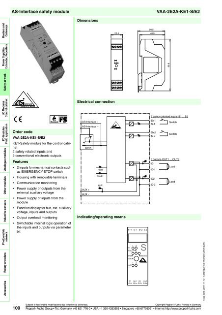
VAA-2E2A-KE1-S/E2 Masters and Gateways Power Supplies, Extender, Repeaters Safety at work I/O Modules Control cabinet I/O Modules Field application Analogue modules Other modules Inductive sensors Photoelectric sensors Rotary encoders Accessories AS-Interface safety module Features 2 inputs for mechanical contacts such as EMERGENCY-STOP switch Housing with removable terminals Communication monitoring Power supply of outputs from the external auxiliary voltage Power supply of inputs from the module Function display for bus, ext. auxiliary voltage, inputs and outputs Output overload monitoring Switchable internal logic operation of the inputs and outputs via parameter bit 100 SAFETY AT WORK Order code VAA-2E2A-KE1-S/E2 KE1-Safety module for the control cabinet 2 safety-related inputs and 2 conventional electronic outputs Dimensions Electrical connection AS-Interface - AS-Interface + ADDR AUX + AUX - PWR FAULT AUX Indicating/operating means VAA-2E2A-KE1-S/E2 Subject to reasonable modifications due to technical advances. Copyright Pepperl+Fuchs, Printed in Germany Pepperl+Fuchs Group Tel.: Germany +49 621 776-0 USA +1 330 4253555 Singapore +65 67799091 Internet http://www.pepperl-fuchs.com 22.5 S+1 S-1 S+2 S-2 1 2 S FAULT PWR ADDR 1 2 OUT S AUX 01 0 1 02 0 2 AS-i+ AS-i AUX+ AUX 50.5 48.5 99.6 2 safety-oriented inputs S1 ... S2 S+1 S-1 S+2 S-2 Switch Switch 2 outputs OUT1 ... OUT2 O1 O-1 O2 O-2 Load Load Issue date 2004-11-19 - Catalogue AS-Interface 2004/2005
Issue date 2004-11-19 - Catalogue AS-Interface 2004/2005 AS-Interface safety module Technical data General specifications Slave type Standard slave Indicators/operating means LED FAULT error display; LED red red: communication error or address is 0 red flashing: Output supply overload LED PWR AS-Interface voltage; LED green LED AUX ext. auxiliary voltage UAUX; LED green LED IN switching state (input); 2 LED yellow LED OUT switching state (output); 2 LED yellow Electrical specifications Auxiliary voltage (output) UAUX 20 ... 30 V DC PELV Protection class III Rated operational voltage Ue 26.5 ... 31.6 V from AS-Interface Rated operational current Ie ≤ 70 mA Input Number/Type 2 safety-related inputs for mechanical contacts, cross-circuit monitored: 2 single-channel contacts: up to category 2 to EN 954-1 or 1 2-channel contact: up to category 4 to EN 954-1 Cable length must exceed 30 m per input. Supply from AS-Interface Voltage 20 ... 30 V DC pulsed Current loading capacity Output input current limited ≤ 15 mA, overload and short-circuit resistant Number/Type 2 conventional electronic outputs, PNP Supply from external auxiliary voltage UAUX Current 0.5 A per output Voltage ≥ (UAUX - 0,5 V) Programming instructions Profile S-7.B IO code 7 ID code B ID1 code F ID2 code 0 Data bits (function via AS-Interface) input output D0 dyn. safety code S1 OUT 1 D1 dyn. safety code S1 OUT 2 D2 dyn. safety code S2 - D3 dyn. safety code S2 - Parameter bits (programmable via AS-i) function P0 Logic operation: P1 ... P3 Standard conformity P0 = 1 (Basic setting): The outputs are controlled via AS-Interface. P0 = 0: The outputs are controlled via AS-Interface or the inputs. The corresponding output is activated on opening the contacts of an input. not used Insulation coordination EN 50178 Electromagnetic compatibility EN 50295, EN 61326, EN 61496-1, EN 61000-6-2, EN 61000- 4-5 1kV asymmetric, criterion B Protection degree EN 60529 Fieldbus standard EN 50295, IEC 62026-2 Functional safety EN 954-1:1996 (up to category 4), BIA Final Draft "Proposal for a principle to the verification and certification of field busses for transmission of safety related signals" 28.05.2000, IEC 61508 up to SIL3 Standards Ambient conditions IEC 60204-1 Ambient temperature -25 ... 50 °C (248 ... 323 K) Storage temperature Mechanical specifications -25 ... 85 °C (248 ... 358 K) Protection degree IP20 Connection removable terminals, terminal connection ≤ 2.5 mm 2 Mass 80 g Mounting DIN rail Notes The cables and the laying of the cables have to meet the standards which apply to the particular application, e.g. IEC 60204. The instructions for the intended use, the selection and the correct connection of the sensors/actuators or the selection and the attainment of the corresponding safety category are given in the manual. The outputs may not be used for safety-related functions! Function VAA-2E2A-KE1-S/E2 The VAA-2E2A-KE1-S/E2 is an AS-Interface safety module with 2 safety-related inputs and 2 conventional outputs. A dual channel mechanical switch or in each case a single channel mechanical switch can be connected to the two safety-related inputs. The outputs are conventional electronic outputs, which may be loaded in total with 1 A (max. 0,5 A per output). The housing, only 22.5 mm in width and 48.5 mm in height, takes up little place in the switch cabinet. The module features an integrated addressing jack is mounted by snapping onto the 35 mm DIN rail in accordance with EN 50022. Plug-in terminals are used for connection. A 4-way terminal block (black) is used for the inputs. The AS-Interface is connected via a double terminal block (yellow). The current switching state of each channel is indicated by an LED, located on the module's top side. Similarly, an LED is provided to monitor the AS-Interface communication and to indicate that the module has the address 0. If a communication error occurs, the outputs are de-energized (only P0=1). When single channel force-directed mechanical switches are connected, up to Category 2 in accordance with EN 954-1 can be achieved, given the appropriate wiring and selection of switch. When a two-channel force-directed mechanical switch is connected, up to Category 4 in accordance with EN 954-1 can be achieved, given the appropriate wiring and selection of switch. As per approval in accordance with IEC 61508 up to SIL 3 can be achieved. Both inputs of the module are assigned. The two channels of the mechanical switch are monitored for a cross circuit. LEDs are also provided to indicate AS-Interface voltage and external power supply. Accessories VBP-HH1 Hand-held programming device VAZ-PK-1,5M-V1-G Connection cable module/hand-held programming device Subject to reasonable modifications due to technical advances. Copyright Pepperl+Fuchs, Printed in Germany Pepperl+Fuchs Group Tel.: Germany +49 621 776-0 USA +1 330 4253555 Singapore +65 67799091 Internet http://www.pepperl-fuchs.com 101 Masters and Gateways Power Supplies, Extender, Repeaters Safety at work I/O Modules Control cabinet I/O Modules Field application Analogue modules Other modules Inductive sensors Photoelectric sensors Rotary encoders Accessories
- Page 45 and 46: Issue date 2004-11-19 - Catalogue A
- Page 47 and 48: Issue date 2004-11-19 - Catalogue A
- Page 49 and 50: Issue date 2004-11-19 - Catalogue A
- Page 51 and 52: Issue date 2004-11-19 - Catalogue A
- Page 53 and 54: Issue date 2004-11-19 - Catalogue A
- Page 55 and 56: Issue date 2004-11-19 - Catalogue A
- Page 57 and 58: Issue date 2004-11-19 - Catalogue A
- Page 59 and 60: Issue date 2004-11-19 - Catalogue A
- Page 61 and 62: Issue date 2004-11-19 - Catalogue A
- Page 63 and 64: Issue date 2004-11-19 - Catalogue A
- Page 65 and 66: Issue date 2004-11-19 - Catalogue A
- Page 67 and 68: Issue date 2004-11-19 - Catalogue A
- Page 69 and 70: Issue date 2004-11-19 - Catalogue A
- Page 71 and 72: Issue date 2004-11-19 - Catalogue A
- Page 73 and 74: Issue date 2004-11-19 - Catalogue A
- Page 75 and 76: Issue date 2004-11-19 - Catalogue A
- Page 77 and 78: Issue date 2004-11-19 - Catalogue A
- Page 79 and 80: Issue date 2004-11-19 - Catalogue A
- Page 81 and 82: Issue date 2004-11-19 - Catalogue A
- Page 83 and 84: Issue date 2004-11-19 - Catalogue A
- Page 85 and 86: Issue date 2004-11-19 - Catalogue A
- Page 87 and 88: Issue date 2004-11-19 - Catalogue A
- Page 89 and 90: Issue date 2004-11-19 - Catalogue A
- Page 91 and 92: Issue date 2004-11-19 - Catalogue A
- Page 93 and 94: Issue date 2004-11-19 - Catalogue A
- Page 95: Issue date 2004-11-19 - Catalogue A
- Page 99 and 100: Issue date 2004-11-19 - Catalogue A
- Page 101 and 102: Issue date 2004-11-19 - Catalogue A
- Page 103 and 104: Issue date 2004-11-19 - Catalogue A
- Page 105 and 106: Issue date 2004-11-19 - Catalogue A
- Page 107 and 108: Issue date 2004-11-19 - Catalogue A
- Page 109 and 110: Issue date 2004-11-19 - Catalogue A
- Page 111 and 112: Issue date 2004-11-19 - Catalogue A
- Page 113 and 114: Issue date 2004-11-19 - Catalogue A
- Page 115 and 116: Issue date 2004-11-19 - Catalogue A
- Page 117 and 118: Issue date 2004-11-19 - Catalogue A
- Page 119 and 120: Issue date 2004-11-19 - Catalogue A
- Page 121 and 122: Issue date 2004-11-19 - Catalogue A
- Page 123 and 124: Issue date 2004-11-19 - Catalogue A
- Page 125 and 126: Issue date 2004-11-19 - Catalogue A
- Page 127 and 128: Issue date 2004-11-19 - Catalogue A
- Page 129 and 130: Issue date 2004-11-19 - Catalogue A
- Page 131 and 132: Issue date 2004-11-19 - Catalogue A
- Page 133 and 134: Issue date 2004-11-19 - Catalogue A
- Page 135 and 136: Issue date 2004-11-19 - Catalogue A
- Page 137 and 138: Issue date 2004-11-19 - Catalogue A
- Page 139 and 140: Issue date 2004-11-19 - Catalogue A
- Page 141 and 142: Issue date 2004-11-19 - Catalogue A
- Page 143 and 144: Issue date 2004-11-19 - Catalogue A
- Page 145 and 146: Issue date 2004-11-19 - Catalogue A
VAA-2E2A-KE1-S/E2<br />
Masters and<br />
Gateways<br />
Power Supplies,<br />
Extender, Repeaters<br />
Safety at work<br />
I/O Modules<br />
Control cabinet<br />
I/O Modules<br />
Field application<br />
Analogue modules<br />
Other modules<br />
Inductive sensors<br />
Photoelectric<br />
sensors<br />
Rotary encoders<br />
Accessories<br />
<strong>AS</strong>-<strong>Interface</strong> safety module<br />
Features<br />
2 inputs for mechanical contacts such<br />
as EMERGENCY-STOP switch<br />
Housing with removable terminals<br />
Communication monitoring<br />
Power supply of outputs from the<br />
external auxiliary voltage<br />
Power supply of inputs from the<br />
module<br />
Function display for bus, ext. auxiliary<br />
voltage, inputs and outputs<br />
Output overload monitoring<br />
Switchable internal logic operation of<br />
the inputs and outputs via parameter<br />
bit<br />
100<br />
SAFETY AT WORK<br />
Order code<br />
VAA-2E2A-KE1-S/E2<br />
KE1-Safety module for the control cabinet<br />
2 safety-related inputs and<br />
2 conventional electronic outputs<br />
Dimensions<br />
Electrical connection<br />
<strong>AS</strong>-<strong>Interface</strong> -<br />
<strong>AS</strong>-<strong>Interface</strong> +<br />
ADDR<br />
AUX +<br />
AUX -<br />
PWR<br />
FAULT<br />
AUX<br />
Indicating/operating means<br />
VAA-2E2A-KE1-S/E2<br />
Subject to reasonable modifications due to technical advances. Copyright Pepperl+Fuchs, Printed in Germany<br />
Pepperl+Fuchs Group Tel.: Germany +49 621 776-0 USA +1 330 4253555 Singapore +65 67799091 Internet http://www.pepperl-fuchs.com<br />
22.5<br />
S+1 S-1 S+2 S-2<br />
1 2<br />
S<br />
FAULT<br />
PWR<br />
ADDR<br />
1 2<br />
OUT<br />
S<br />
AUX<br />
01 0 1 02 0 2<br />
<strong>AS</strong>-i+ <strong>AS</strong>-i AUX+ AUX<br />
50.5<br />
48.5<br />
99.6<br />
2 safety-oriented inputs S1 ... S2<br />
S+1<br />
S-1<br />
S+2<br />
S-2<br />
Switch<br />
Switch<br />
2 outputs OUT1 ... OUT2<br />
O1<br />
O-1<br />
O2<br />
O-2<br />
Load<br />
Load<br />
Issue date 2004-11-19 - Catalogue <strong>AS</strong>-<strong>Interface</strong> 2004/2005


