Sensor systems 2 AS-Interface
Sensor systems 2 AS-Interface Sensor systems 2 AS-Interface
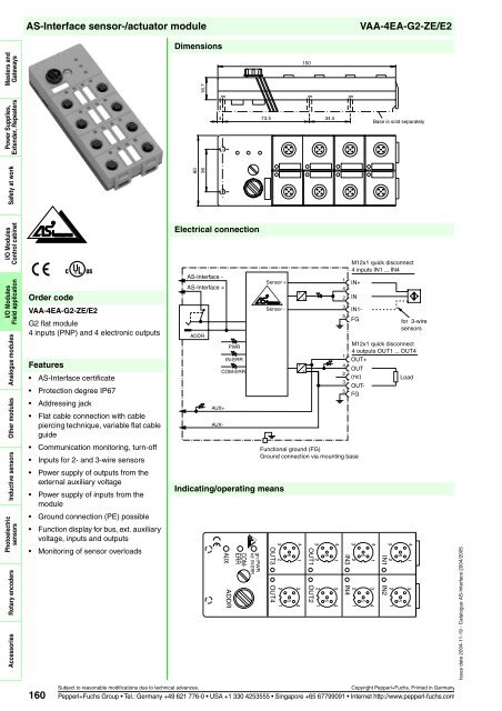
VAA-4EA-G2-ZE/E2 Masters and Gateways Power Supplies, Extender, Repeaters Safety at work I/O Modules Control cabinet I/O Modules Field application Analogue modules Other modules Inductive sensors Photoelectric sensors Rotary encoders Accessories AS-Interface sensor-/actuator module Features AS-Interface certificate Protection degree IP67 Addressing jack Flat cable connection with cable piercing technique, variable flat cable guide Communication monitoring, turn-off Inputs for 2- and 3-wire sensors Power supply of outputs from the external auxiliary voltage Power supply of inputs from the module Ground connection (PE) possible Function display for bus, ext. auxiliary voltage, inputs and outputs Monitoring of sensor overloads 160 U® Order code VAA-4EA-G2-ZE/E2 G2 flat module 4 inputs (PNP) and 4 electronic outputs Dimensions 18.7 60 36 Electrical connection AS-Interface - AS-Interface + ADDR AUX+ AUX- 4 73.5 34.5 PWR IN-ERR COM-ERR Sensor + Indicating/operating means AUX ADDR gn: PWR rd: IN-ERR COM- ERR VAA-4EA-G2-ZE/E2 Base is sold separately Subject to reasonable modifications due to technical advances. Copyright Pepperl+Fuchs, Printed in Germany Pepperl+Fuchs Group Tel.: Germany +49 621 776-0 USA +1 330 4253555 Singapore +65 67799091 Internet http://www.pepperl-fuchs.com Sensor - 150 1 4 2 3 5 1 4 2 3 5 M12x1 quick disconnect 4 inputs IN1 ... IN4 IN+ IN IN1- FG Functional ground (FG) Ground connection via mounting base 4 1 3 4 5 5 3 2 2 1 OUT3 OUT4 4 1 3 4 5 5 3 2 2 1 OUT1 OUT2 for 3-wire sensors M12x1 quick disconnect 4 outputs OUT1 ... OUT4 OUT+ OUT (nc) Load OUT- FG 3 4 1 3 4 5 5 2 2 1 IN3 IN4 3 4 1 3 4 5 5 2 2 1 IN1 IN2 Issue date 2004-11-19 - Catalogue AS-Interface 2004/2005
Issue date 2004-11-19 - Catalogue AS-Interface 2004/2005 AS-Interface sensor-/actuator module Technical data General specifications Slave type Indicators/operating means Standard slave LED PWR AS-Interface voltage; LED green LED COM ERR communication error / address is 0; LED red LED AUX ext. auxiliary voltage UAUX; LED green LED IN switching state (input); 4 LED yellow LED OUT switching state (output); 4 LED yellow LED IN-ERR Electrical specifications overload of sensor power supply; LED red Auxiliary voltage (output) UAUX 24 V DC ± 15 % PELV Protection class III Rated operational voltage Ue 26.5 ... 31.6 V from AS-Interface Rated operational current Ie ≤ 40 mA (without sensors) / max. 240 mA Input Number/Type 4 inputs for 2- or 3-wire sensors (PNP), DC Supply from AS-Interface Voltage 21 ... 31 V Current loading capacity ≤ 200 mA (T B ≤ 40 °C), ≤ 150 mA (T B ≤ 60 °C), short-circuit protected Input current ≤ 8 mA (limited internally) Switching point 0 (unattenuated) ≤ 1.5 mA 1 (attenuated) ≥ 4.5 mA Output Number/Type 4 electronic outputs, PNP Supply from external auxiliary voltage U AUX Current 2 A per output, 4 A total Voltage ≥ (U AUX - 0,5 V) Programming instructions Profile S-7.F IO code 7 ID code F Data bits (function via AS-Interface) input output D0 IN1 OUT1 D1 IN2 OUT2 D2 IN3 OUT3 D3 IN4 OUT4 Parameter bits (programmable via AS-i) function P0 communication monitoring P0 = 1 (basic setting), monitoring = ON, i.e. if communication fails, the outputs are de-energised P0 = 0, monitoring = OFF, if communication fails, the outputs maintain their condition P1 not used P2 not used P3 Ambient conditions not used Ambient temperature -25 ... 60 °C (248 ... 333 K) Storage temperature Mechanical specifications -25 ... 85 °C (248 ... 358 K) Protection degree IP67 according to EN 60529 Connection cable piercing method flat cable yellow/flat cable black inputs/outputs: M12 round connector Mass 150 g Mounting Mounting base Function VAA-4EA-G2-ZE/E2 The VAA-4EA-G2-ZE/E2 is an AS-Interface coupling module with 4 inputs and 4 outputs. Mechanical contacts and 2- and 3-wire sensors can be connected to the inputs. The outputs are electronic outputs, which can be loaded to 24 V DC and 2 A per output. The IP67 flat module features an integrated addressing jack and is ideal for applications in the field. Connection to the sensors/actuators is provided via M12 x 1 screw connections. The current switching state of each channel is indicated by an LED, located on the module's top side. Similarly, an LED is provided to monitor the AS-Interface communication and to indicate that the module has the address 0. If an AS-Interface communication error occurs, the outputs are de-energised in case the watchdog is active. The input is monitored for short circuits. LEDs are also provided to indicate AS-Interface voltage and external power supply. The U-G2FF mounting base is used as a standard connection to the AS-Interface flat cable and to the external 24 V DC power supply. The specially designed base enables the user to connect flat cables from both sides. This means, for example, that 90° curves can be laid with very tight radii (variable flat cable guide). Note: The mounting base for the module is sold separately. Accessories VBP-HH1 Hand-held programming device VAZ-PK-1,5M-V1-G Connection cable module/hand-held programming device VAZ-FK-ED-G2 AS-Interface end seal for G2 modules Matching system components U-G2FF Mounting plate for connection to flat cable (AS-Interface and external auxiliary power) Subject to reasonable modifications due to technical advances. Copyright Pepperl+Fuchs, Printed in Germany Pepperl+Fuchs Group Tel.: Germany +49 621 776-0 USA +1 330 4253555 Singapore +65 67799091 Internet http://www.pepperl-fuchs.com 161 Masters and Gateways Power Supplies, Extender, Repeaters Safety at work I/O Modules Control cabinet I/O Modules Field application Analogue modules Other modules Inductive sensors Photoelectric sensors Rotary encoders Accessories
- Page 105 and 106: Issue date 2004-11-19 - Catalogue A
- Page 107 and 108: Issue date 2004-11-19 - Catalogue A
- Page 109 and 110: Issue date 2004-11-19 - Catalogue A
- Page 111 and 112: Issue date 2004-11-19 - Catalogue A
- Page 113 and 114: Issue date 2004-11-19 - Catalogue A
- Page 115 and 116: Issue date 2004-11-19 - Catalogue A
- Page 117 and 118: Issue date 2004-11-19 - Catalogue A
- Page 119 and 120: Issue date 2004-11-19 - Catalogue A
- Page 121 and 122: Issue date 2004-11-19 - Catalogue A
- Page 123 and 124: Issue date 2004-11-19 - Catalogue A
- Page 125 and 126: Issue date 2004-11-19 - Catalogue A
- Page 127 and 128: Issue date 2004-11-19 - Catalogue A
- Page 129 and 130: Issue date 2004-11-19 - Catalogue A
- Page 131 and 132: Issue date 2004-11-19 - Catalogue A
- Page 133 and 134: Issue date 2004-11-19 - Catalogue A
- Page 135 and 136: Issue date 2004-11-19 - Catalogue A
- Page 137 and 138: Issue date 2004-11-19 - Catalogue A
- Page 139 and 140: Issue date 2004-11-19 - Catalogue A
- Page 141 and 142: Issue date 2004-11-19 - Catalogue A
- Page 143 and 144: Issue date 2004-11-19 - Catalogue A
- Page 145 and 146: Issue date 2004-11-19 - Catalogue A
- Page 147 and 148: Issue date 2004-11-19 - Catalogue A
- Page 149 and 150: Issue date 2004-11-19 - Catalogue A
- Page 151 and 152: Issue date 2004-11-19 - Catalogue A
- Page 153 and 154: Issue date 2004-11-19 - Catalogue A
- Page 155: Issue date 2004-11-19 - Catalogue A
- Page 159 and 160: Issue date 2004-11-19 - Catalogue A
- Page 161 and 162: Issue date 2004-11-19 - Catalogue A
- Page 163 and 164: Issue date 2004-11-19 - Catalogue A
- Page 165 and 166: Issue date 2004-11-19 - Catalogue A
- Page 167 and 168: Issue date 2004-11-19 - Catalogue A
- Page 169 and 170: Issue date 2004-11-19 - Catalogue A
- Page 171 and 172: Issue date 2004-11-19 - Catalogue A
- Page 173 and 174: Issue date 2004-11-19 - Catalogue A
- Page 175 and 176: Issue date 2004-11-19 - Catalogue A
- Page 177 and 178: Issue date 2004-11-19 - Catalogue A
- Page 179 and 180: Issue date 2004-11-19 - Catalogue A
- Page 181 and 182: Issue date 2004-11-19 - Catalogue A
- Page 183 and 184: Issue date 2004-11-19 - Catalogue A
- Page 185 and 186: Issue date 2004-11-19 - Catalogue A
- Page 187 and 188: Issue date 2004-11-19 - Catalogue A
- Page 189 and 190: Issue date 2004-11-19 - Catalogue A
- Page 191 and 192: Issue date 2004-11-19 - Catalogue A
- Page 193 and 194: Issue date 2004-11-19 - Catalogue A
- Page 195 and 196: Issue date 2004-11-19 - Catalogue A
- Page 197 and 198: Issue date 2004-11-19 - Catalogue A
- Page 199 and 200: Issue date 2004-11-19 - Catalogue A
- Page 201 and 202: Issue date 2004-11-19 - Catalogue A
- Page 203 and 204: Issue date 2004-11-19 - Catalogue A
- Page 205 and 206: Issue date 2004-11-19 - Catalogue A
VAA-4EA-G2-ZE/E2<br />
Masters and<br />
Gateways<br />
Power Supplies,<br />
Extender, Repeaters<br />
Safety at work<br />
I/O Modules<br />
Control cabinet<br />
I/O Modules<br />
Field application<br />
Analogue modules<br />
Other modules<br />
Inductive sensors<br />
Photoelectric<br />
sensors<br />
Rotary encoders<br />
Accessories<br />
<strong>AS</strong>-<strong>Interface</strong> sensor-/actuator module<br />
Features<br />
<strong>AS</strong>-<strong>Interface</strong> certificate<br />
Protection degree IP67<br />
Addressing jack<br />
Flat cable connection with cable<br />
piercing technique, variable flat cable<br />
guide<br />
Communication monitoring, turn-off<br />
Inputs for 2- and 3-wire sensors<br />
Power supply of outputs from the<br />
external auxiliary voltage<br />
Power supply of inputs from the<br />
module<br />
Ground connection (PE) possible<br />
Function display for bus, ext. auxiliary<br />
voltage, inputs and outputs<br />
Monitoring of sensor overloads<br />
160<br />
U®<br />
Order code<br />
VAA-4EA-G2-ZE/E2<br />
G2 flat module<br />
4 inputs (PNP) and 4 electronic outputs<br />
Dimensions<br />
18.7<br />
60<br />
36<br />
Electrical connection<br />
<strong>AS</strong>-<strong>Interface</strong> -<br />
<strong>AS</strong>-<strong>Interface</strong> +<br />
ADDR<br />
AUX+<br />
AUX-<br />
4 73.5 34.5<br />
PWR<br />
IN-ERR<br />
COM-ERR<br />
<strong>Sensor</strong> +<br />
Indicating/operating means<br />
AUX<br />
ADDR<br />
gn: PWR<br />
rd: IN-ERR<br />
COM-<br />
ERR<br />
VAA-4EA-G2-ZE/E2<br />
Base is sold separately<br />
Subject to reasonable modifications due to technical advances. Copyright Pepperl+Fuchs, Printed in Germany<br />
Pepperl+Fuchs Group Tel.: Germany +49 621 776-0 USA +1 330 4253555 Singapore +65 67799091 Internet http://www.pepperl-fuchs.com<br />
<strong>Sensor</strong> -<br />
150<br />
1<br />
4<br />
2<br />
3<br />
5<br />
1<br />
4<br />
2<br />
3<br />
5<br />
M12x1 quick disconnect<br />
4 inputs IN1 ... IN4<br />
IN+<br />
IN<br />
IN1-<br />
FG<br />
Functional ground (FG)<br />
Ground connection via mounting base<br />
4 1<br />
3 4<br />
5<br />
5<br />
3 2<br />
2 1<br />
OUT3 OUT4<br />
4 1<br />
3 4<br />
5<br />
5<br />
3 2<br />
2 1<br />
OUT1 OUT2<br />
for 3-wire<br />
sensors<br />
M12x1 quick disconnect<br />
4 outputs OUT1 ... OUT4<br />
OUT+<br />
OUT<br />
(nc)<br />
Load<br />
OUT-<br />
FG<br />
3<br />
4<br />
1<br />
3 4<br />
5<br />
5<br />
2<br />
2 1<br />
IN3 IN4<br />
3<br />
4<br />
1<br />
3 4<br />
5<br />
5<br />
2<br />
2 1<br />
IN1 IN2<br />
Issue date 2004-11-19 - Catalogue <strong>AS</strong>-<strong>Interface</strong> 2004/2005


