Sensor systems 2 AS-Interface
Sensor systems 2 AS-Interface Sensor systems 2 AS-Interface
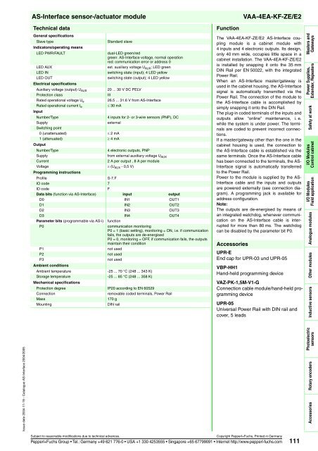
VAA-4EA-KF-ZE/E2 Masters and Gateways Power Supplies, Extender, Repeaters Safety at work I/O Modules Control cabinet I/O Modules Field application Analogue modules Other modules Inductive sensors Photoelectric sensors Rotary encoders Accessories AS-Interface sensor-/actuator module Features AS-Interface certificate Housing with removable, coded terminals AS-Interface connection via Power Rail Communication monitoring, turn-off Outputs loadable up to 8 A (per module) Addressing jack Power supply of outputs from the external auxiliary voltage External power supply of sensors Function display for bus, ext. auxiliary voltage, inputs and outputs 110 U® Order code VAA-4EA-KF-ZE/E2 Cabinet module 4 inputs (PNP) and 4 electronic outputs Dimensions 40 Electrical connection AS-Interface - AS-Interface - AS-Interface + AS-Interface + Power Rail 2 8 1 7 5 4 3 ADDR Indicating/operating means Terminal for wall mounting VAA-4EA-KF-ZE/E2 Subject to reasonable modifications due to technical advances. Copyright Pepperl+Fuchs, Printed in Germany Pepperl+Fuchs Group Tel.: Germany +49 621 776-0 USA +1 330 4253555 Singapore +65 67799091 Internet http://www.pepperl-fuchs.com PWR/ FAULT 114 13 +IN1 15 +IN2 19 +IN3 21 14 +IN4 20 -IN 16 18 22 24 17 23 4 6 5 10 1 2 3 4 5 6 7 8 9 10 11 12 IN1 IN2 ADDR IN3 IN4 PWR/ FAULT OUT1 OUT2 OUT3 OUT4 AUX 13 14 15 16 17 18 19 20 21 22 23 24 +OUT1 +OUT2 +OUT3 +OUT4 -OUT 107 93 + 24 V PELV for 3-wire sensors Load -AUX for connection +AUX of UAUX Issue date 2004-11-19 - Catalogue AS-Interface 2004/2005
Issue date 2004-11-19 - Catalogue AS-Interface 2004/2005 AS-Interface sensor-/actuator module Technical data General specifications Slave type Indicators/operating means Standard slave LED PWR/FAULT dual-LED green/red green: AS-Interface voltage, normal operation red: communication error or address 0 LED AUX ext. auxiliary voltage UAUX; LED green LED IN switching state (input); 4 LED yellow LED OUT Electrical specifications switching state (output); 4 LED yellow Auxiliary voltage (output) UAUX 20 ... 30 V DC PELV Protection class III Rated operational voltage Ue 26.5 ... 31.6 V from AS-Interface Rated operational current Ie ≤ 30 mA Input Number/Type 4 inputs for 2- or 3-wire sensors (PNP), DC Supply external Switching point 0 (unattenuated) ≤ 2 mA 1 (attenuated) ≥ 4 mA Output Number/Type 4 electronic outputs, PNP Supply from external auxiliary voltage U AUX Current 2 A per output , 8 A per module Voltage ≥ (U AUX - 0,5 V) Programming instructions Profile S-7.F IO code 7 ID code F Data bits (function via AS-Interface) input output D0 IN1 OUT1 D1 IN2 OUT2 D2 IN3 OUT3 D3 IN4 OUT4 Parameter bits (programmable via AS-i) function P0 communication monitoring P0 = 1 (basic setting), monitoring = ON, i.e. if communication fails, the outputs are de-energised P0 = 0, monitoring = OFF, if communication fails, the outputs maintain their condition P1 not used P2 not used P3 Ambient conditions not used Ambient temperature -25 ... 70 °C (248 ... 343 K) Storage temperature Mechanical specifications -25 ... 85 °C (248 ... 358 K) Protection degree IP20 according to EN 60529 Connection removable coded terminals, Power Rail Mass 170 g Mounting DIN rail Function VAA-4EA-KF-ZE/E2 The VAA-4EA-KF-ZE/E2 AS-Interface coupling module is a cabinet module with 4 inputs and 4 electronic outputs. Its design, only 40 mm wide, occupies little space in a cabinet installation. The VAA-4EA-KF-ZE/E2 is installed by snapping it onto the 35 mm DIN Rail per EN 50022, with the integrated Power Rail. When an AS-Interface master/gateway is used in the cabinet housing, the AS-Interface signal is automatically transmitted via the Power Rail. The connection of the module to the AS-Interface cable is accomplished by simply snapping it onto the DIN Rail. The plug-in coded terminals of the inputs and outputs allow "online" maintenance, i. e. while the system is under power. The terminals are coded to prevent incorrect connections. If a master/gateway other than the one in the cabinet housing is used, the connection to the AS-Interface cable is established via the same terminals. Once the AS-Interface cable has been connected to the terminals, the AS- Interface signal is automatically transferred to the Power Rail. Power to the module is supplied by the AS- Interface cable and the inputs and outputs are powered externally (see connection diagram). A programming jack is available for address configuration. Note: The outputs are de-energised by means of an integrated watchdog, whenever communication on the AS-Interface cable is interrupted for more than 80 ms. The watchdog can be disabled by the parameter bit P0. Accessories UPR-E End cap for UPR-03 und UPR-05 VBP-HH1 Hand-held programming device VAZ-PK-1,5M-V1-G Connection cable module/hand-held programming device UPR-05 Universal Power Rail with DIN rail and cover, 5 leads Subject to reasonable modifications due to technical advances. Copyright Pepperl+Fuchs, Printed in Germany Pepperl+Fuchs Group Tel.: Germany +49 621 776-0 USA +1 330 4253555 Singapore +65 67799091 Internet http://www.pepperl-fuchs.com 111 Masters and Gateways Power Supplies, Extender, Repeaters Safety at work I/O Modules Control cabinet I/O Modules Field application Analogue modules Other modules Inductive sensors Photoelectric sensors Rotary encoders Accessories
- Page 55 and 56: Issue date 2004-11-19 - Catalogue A
- Page 57 and 58: Issue date 2004-11-19 - Catalogue A
- Page 59 and 60: Issue date 2004-11-19 - Catalogue A
- Page 61 and 62: Issue date 2004-11-19 - Catalogue A
- Page 63 and 64: Issue date 2004-11-19 - Catalogue A
- Page 65 and 66: Issue date 2004-11-19 - Catalogue A
- Page 67 and 68: Issue date 2004-11-19 - Catalogue A
- Page 69 and 70: Issue date 2004-11-19 - Catalogue A
- Page 71 and 72: Issue date 2004-11-19 - Catalogue A
- Page 73 and 74: Issue date 2004-11-19 - Catalogue A
- Page 75 and 76: Issue date 2004-11-19 - Catalogue A
- Page 77 and 78: Issue date 2004-11-19 - Catalogue A
- Page 79 and 80: Issue date 2004-11-19 - Catalogue A
- Page 81 and 82: Issue date 2004-11-19 - Catalogue A
- Page 83 and 84: Issue date 2004-11-19 - Catalogue A
- Page 85 and 86: Issue date 2004-11-19 - Catalogue A
- Page 87 and 88: Issue date 2004-11-19 - Catalogue A
- Page 89 and 90: Issue date 2004-11-19 - Catalogue A
- Page 91 and 92: Issue date 2004-11-19 - Catalogue A
- Page 93 and 94: Issue date 2004-11-19 - Catalogue A
- Page 95 and 96: Issue date 2004-11-19 - Catalogue A
- Page 97 and 98: Issue date 2004-11-19 - Catalogue A
- Page 99 and 100: Issue date 2004-11-19 - Catalogue A
- Page 101 and 102: Issue date 2004-11-19 - Catalogue A
- Page 103 and 104: Issue date 2004-11-19 - Catalogue A
- Page 105: Issue date 2004-11-19 - Catalogue A
- Page 109 and 110: Issue date 2004-11-19 - Catalogue A
- Page 111 and 112: Issue date 2004-11-19 - Catalogue A
- Page 113 and 114: Issue date 2004-11-19 - Catalogue A
- Page 115 and 116: Issue date 2004-11-19 - Catalogue A
- Page 117 and 118: Issue date 2004-11-19 - Catalogue A
- Page 119 and 120: Issue date 2004-11-19 - Catalogue A
- Page 121 and 122: Issue date 2004-11-19 - Catalogue A
- Page 123 and 124: Issue date 2004-11-19 - Catalogue A
- Page 125 and 126: Issue date 2004-11-19 - Catalogue A
- Page 127 and 128: Issue date 2004-11-19 - Catalogue A
- Page 129 and 130: Issue date 2004-11-19 - Catalogue A
- Page 131 and 132: Issue date 2004-11-19 - Catalogue A
- Page 133 and 134: Issue date 2004-11-19 - Catalogue A
- Page 135 and 136: Issue date 2004-11-19 - Catalogue A
- Page 137 and 138: Issue date 2004-11-19 - Catalogue A
- Page 139 and 140: Issue date 2004-11-19 - Catalogue A
- Page 141 and 142: Issue date 2004-11-19 - Catalogue A
- Page 143 and 144: Issue date 2004-11-19 - Catalogue A
- Page 145 and 146: Issue date 2004-11-19 - Catalogue A
- Page 147 and 148: Issue date 2004-11-19 - Catalogue A
- Page 149 and 150: Issue date 2004-11-19 - Catalogue A
- Page 151 and 152: Issue date 2004-11-19 - Catalogue A
- Page 153 and 154: Issue date 2004-11-19 - Catalogue A
- Page 155 and 156: Issue date 2004-11-19 - Catalogue A
Issue date 2004-11-19 - Catalogue <strong>AS</strong>-<strong>Interface</strong> 2004/2005<br />
<strong>AS</strong>-<strong>Interface</strong> sensor-/actuator module<br />
Technical data<br />
General specifications<br />
Slave type<br />
Indicators/operating means<br />
Standard slave<br />
LED PWR/FAULT dual-LED green/red<br />
green: <strong>AS</strong>-<strong>Interface</strong> voltage, normal operation<br />
red: communication error or address 0<br />
LED AUX ext. auxiliary voltage UAUX; LED green<br />
LED IN switching state (input); 4 LED yellow<br />
LED OUT<br />
Electrical specifications<br />
switching state (output); 4 LED yellow<br />
Auxiliary voltage (output) UAUX 20 ... 30 V DC PELV<br />
Protection class III<br />
Rated operational voltage Ue 26.5 ... 31.6 V from <strong>AS</strong>-<strong>Interface</strong><br />
Rated operational current Ie ≤ 30 mA<br />
Input<br />
Number/Type 4 inputs for 2- or 3-wire sensors (PNP), DC<br />
Supply external<br />
Switching point<br />
0 (unattenuated) ≤ 2 mA<br />
1 (attenuated) ≥ 4 mA<br />
Output<br />
Number/Type 4 electronic outputs, PNP<br />
Supply from external auxiliary voltage U AUX<br />
Current 2 A per output , 8 A per module<br />
Voltage ≥ (U AUX - 0,5 V)<br />
Programming instructions<br />
Profile S-7.F<br />
IO code 7<br />
ID code F<br />
Data bits (function via <strong>AS</strong>-<strong>Interface</strong>) input output<br />
D0 IN1 OUT1<br />
D1 IN2 OUT2<br />
D2 IN3 OUT3<br />
D3 IN4 OUT4<br />
Parameter bits (programmable via <strong>AS</strong>-i) function<br />
P0 communication monitoring<br />
P0 = 1 (basic setting), monitoring = ON, i.e. if communication<br />
fails, the outputs are de-energised<br />
P0 = 0, monitoring = OFF, if communication fails, the outputs<br />
maintain their condition<br />
P1 not used<br />
P2 not used<br />
P3<br />
Ambient conditions<br />
not used<br />
Ambient temperature -25 ... 70 °C (248 ... 343 K)<br />
Storage temperature<br />
Mechanical specifications<br />
-25 ... 85 °C (248 ... 358 K)<br />
Protection degree IP20 according to EN 60529<br />
Connection removable coded terminals, Power Rail<br />
Mass 170 g<br />
Mounting DIN rail<br />
Function<br />
VAA-4EA-KF-ZE/E2<br />
The VAA-4EA-KF-ZE/E2 <strong>AS</strong>-<strong>Interface</strong> coupling<br />
module is a cabinet module with<br />
4 inputs and 4 electronic outputs. Its design,<br />
only 40 mm wide, occupies little space in a<br />
cabinet installation. The VAA-4EA-KF-ZE/E2<br />
is installed by snapping it onto the 35 mm<br />
DIN Rail per EN 50022, with the integrated<br />
Power Rail.<br />
When an <strong>AS</strong>-<strong>Interface</strong> master/gateway is<br />
used in the cabinet housing, the <strong>AS</strong>-<strong>Interface</strong><br />
signal is automatically transmitted via the<br />
Power Rail. The connection of the module to<br />
the <strong>AS</strong>-<strong>Interface</strong> cable is accomplished by<br />
simply snapping it onto the DIN Rail.<br />
The plug-in coded terminals of the inputs and<br />
outputs allow "online" maintenance, i. e.<br />
while the system is under power. The terminals<br />
are coded to prevent incorrect connections.<br />
If a master/gateway other than the one in the<br />
cabinet housing is used, the connection to<br />
the <strong>AS</strong>-<strong>Interface</strong> cable is established via the<br />
same terminals. Once the <strong>AS</strong>-<strong>Interface</strong> cable<br />
has been connected to the terminals, the <strong>AS</strong>-<br />
<strong>Interface</strong> signal is automatically transferred<br />
to the Power Rail.<br />
Power to the module is supplied by the <strong>AS</strong>-<br />
<strong>Interface</strong> cable and the inputs and outputs<br />
are powered externally (see connection diagram).<br />
A programming jack is available for<br />
address configuration.<br />
Note:<br />
The outputs are de-energised by means of<br />
an integrated watchdog, whenever communication<br />
on the <strong>AS</strong>-<strong>Interface</strong> cable is interrupted<br />
for more than 80 ms. The watchdog<br />
can be disabled by the parameter bit P0.<br />
Accessories<br />
UPR-E<br />
End cap for UPR-03 und UPR-05<br />
VBP-HH1<br />
Hand-held programming device<br />
VAZ-PK-1,5M-V1-G<br />
Connection cable module/hand-held programming<br />
device<br />
UPR-05<br />
Universal Power Rail with DIN rail and<br />
cover, 5 leads<br />
Subject to reasonable modifications due to technical advances. Copyright Pepperl+Fuchs, Printed in Germany<br />
Pepperl+Fuchs Group Tel.: Germany +49 621 776-0 USA +1 330 4253555 Singapore +65 67799091 Internet http://www.pepperl-fuchs.com 111<br />
Masters and<br />
Gateways<br />
Power Supplies,<br />
Extender, Repeaters<br />
Safety at work<br />
I/O Modules<br />
Control cabinet<br />
I/O Modules<br />
Field application<br />
Analogue modules<br />
Other modules<br />
Inductive sensors<br />
Photoelectric<br />
sensors<br />
Rotary encoders<br />
Accessories


