Instructions for use
Instructions for use
Instructions for use

You also want an ePaper? Increase the reach of your titles
YUMPU automatically turns print PDFs into web optimized ePapers that Google loves.
.<br />
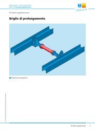
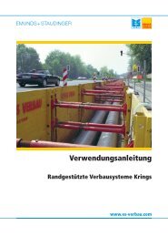
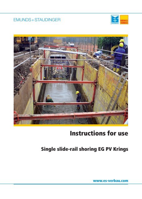
<strong>Instructions</strong> <strong>for</strong> <strong>use</strong><br />
Single slide-rail shoring EG PV Krings<br />
www.es-verbau.com
2<br />
Table of contents<br />
System overview.............................................................................................................................................................3<br />
Occupational safety and general remarks according to DIN EN 13331-1/2...................................................................4<br />
Technical data sheet single slide-rail shoring EG PV (RS)..............................................................................................6<br />
Slide rail panels Krings sliding rail systems..............................................................................................................7<br />
Single slide rail system EG PV..................................................................................................................................9<br />
Assembly instructions <strong>for</strong> the frame <strong>for</strong> single slide-rail shoring EG PV and single slide-rail shoring EG PV with piling<br />
frame KKP KD6 CPS.....................................................................................................................................................12<br />
Adapting the U-type roller unit <strong>for</strong> <strong>use</strong> in single slide-rail shoring EG PV and in single slide-rail shoring EG PV with<br />
piling frame KKP KD6 CPS...........................................................................................................................................14<br />
Installation instructions <strong>for</strong> single slide-rail shoring EG PV...........................................................................................15<br />
<strong>Instructions</strong> <strong>for</strong> removing single slide-rail shoring EG PV.............................................................................................19<br />
Installation instructions <strong>for</strong> single slide-rail shoring EG PV with piling frame KKP KD6 CPS.......................................21<br />
Technical data sheet single slide-rail corner shoring....................................................................................................27<br />
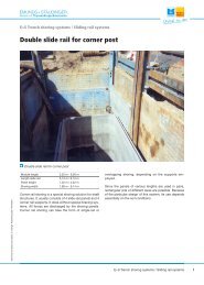
Corner post EG Eck / DG Eck................................................................................................................................28<br />
Installation instructions <strong>for</strong> single slide-rail corner shoring...........................................................................................30<br />
Imprint..........................................................................................................................................................................33
.<br />
Technical contents are subject to change. Publishing date 29/01/2010<br />
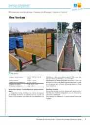
System overview<br />
Single slide rail shoring EG PV (RS)<br />
Module length 2,27 m - 7,27 m<br />
Length slide rail 4,04 m<br />
Panel height 1,32 m / 2,39 m<br />
Pipe culvert height variable<br />
Designation <strong>for</strong> slide-rail system X con<strong>for</strong>ming to EN 13331-1:<br />
e. g.: RS - X - FR - F - 4,04 - 0,43 - max. 1,80<br />
Single slide rail shoring EG PV<br />
U-type roller unit (RS)<br />
Module length 2,27 m - 7,27 m<br />
Length slide rail 4,04 m<br />
Panel height 1,32 m / 2,39 m<br />
Pipe culvert height variable<br />
Designation <strong>for</strong> slide-rail system X con<strong>for</strong>ming to EN 13331-1:<br />
e. g.: RS - X - FR - F - 4,04 - 0,43 - max. 1,80<br />
Single slide rail shoring EG PV (RS) with piling frame KKP KD6 CPS<br />
Module length 4,39 m<br />
Length slide rail 4,04 m<br />
Height sheet pile element 1,00 m<br />
Length sheet piles (KD VI / 8) variable<br />
Designation <strong>for</strong> slide-rail system X con<strong>for</strong>ming to EN 13331-1:<br />
e. g.: RS - X - FR - F - 4,04 - 0,43 - max. 1,80<br />
Usage instruction single slide-rail shoring EG PV Krings<br />
3
.<br />
Occupational safety and general remarks according to DIN EN<br />
13331-1/2<br />
Lifting, handling, pulling, dragging<br />
Measures to reduce hazards<br />
Handling should be carried out as close to the ground as possible.<br />
Slings (chain type and thickness, load hooks) must be chosen to suit the weight being<br />
handled (e.g. trench box or slide rail).<br />
To prevent the accidental detachment of the load during lifting, pulling or handling, only<br />
load hooks with safety catches may be <strong>use</strong>d.<br />
Particularly when pulling loads, the pulling <strong>for</strong>ces defined in section 7.4.16 in DIN EN<br />
13331/1 must be observed.<br />
The load must be slung in such a way that the shoring is in a horizontal position and<br />
swinging during handling is reduced to a minimum.<br />
The shoring must be lowered onto level and firm ground.<br />
It is prohibited to stand within the pivoting range of the excavator/crane and beneath<br />
suspended loads.<br />
A load operator may only stand to the front left of the excavator, in constant eye contact<br />
with the machine operator.<br />
It is always prohibited to stand within the danger zone.<br />
Observe the industrial safety ordinance and the accident prevention regulations <strong>for</strong><br />
lifting gear.<br />
The safety of vehicles and persons on site must be ensured with the aid of cones,<br />
warning tape or safety staff specially deployed <strong>for</strong> this purpose.<br />
The construction site should be sufficiently marked as such with the aid of warning<br />
signs, <strong>for</strong> instance.<br />
The risk of instability as a consequence of wind loads when setting up the shoring on<br />
the edge of the trench must be considered.<br />
The shoring should be secured against accidental impacts and set up in a sufficiently<br />
stable position (sufficient width and firm ground).<br />
When handling, installing and removing shoring, watch out <strong>for</strong> overhead power cables.<br />
On sloping or uneven ground, the shoring should be set up if possible at right angles to<br />
the slope.<br />
4 Usage instruction single slide-rail shoring EG PV Krings<br />
Technical contents are subject to change. Publishing date 29/01/2010
.<br />
Technical contents are subject to change. Publishing date 29/01/2010<br />
Reasons <strong>for</strong> taking parts out of service and instructions <strong>for</strong> repair<br />
Be<strong>for</strong>e <strong>use</strong>, all shoring components must be checked <strong>for</strong><br />
their correct function.<br />
Reasons <strong>for</strong> taking worn or damaged parts out of service<br />
include:<br />
• Missing parts, such as nuts, screws, posts, pins and<br />
stabilizers.<br />
• Broken parts such as spindles, pins and spreader<br />
systems in general.<br />
• If parts are severely de<strong>for</strong>med or misshapen or if there<br />
are holes in panel bodies, <strong>for</strong> instance, the<br />
manufacturer should be consulted in cases of doubt.<br />
• In all cases of doubt, always consult the manufacturer.<br />
Procedure in the event of an accident<br />
Faulty parts must be replaced or repaired.<br />
Minor repairs can be carried out by the <strong>use</strong>r, after<br />
consultation with the manufacturer.<br />
Only original replacement parts from the manufacturer may<br />
be <strong>use</strong>d.<br />
There is no warranty on incorrectly per<strong>for</strong>med repairs and<br />
the <strong>use</strong> of non-original parts.<br />
The requirements of the industrial safety ordinance apply.<br />
In the event of an accident, casualties must be given first aid immediately.<br />
The scene of the accident must be cordoned off and left unchanged.<br />
If the injured person is expected to be unfit <strong>for</strong> work, an accident insurance doctor must<br />
be consulted.<br />
All accidents must be reported immediately to the superior or his deputy.<br />
The accident must be entered in the accident record book.<br />
The currently valid versions of the following documents apply:<br />
• Provisions of the Civil Engineering Committee of the Accident Insurance Institution<br />
• DIN 4124 "Baugruben und Gräben" (pits and trenches)<br />
• DIN EN 13331, Part 1: Product Specifications, Part 2: Assessment by Calculation or Test<br />
• General safety instructions and the relevant industrial safety ordinances<br />
Our products bear the "Geprüfte Sicherheit" (GS) quality seal.<br />
During installation, the instructions contained in the manufacturer's manual must be referred to and observed.<br />
Usage instruction single slide-rail shoring EG PV Krings<br />
5
Technical data sheet single slide-rail shoring EG PV (RS)<br />
6 Usage instruction single slide-rail shoring EG PV Krings<br />
Technical contents are subject to change. Publishing date 29/01/2010
Technical contents are subject to change. Publishing date 29/01/2010<br />
Slide rail panels Krings sliding rail systems<br />
Base panel KRI (height 2.32 m)<br />
Art. No.<br />
151 096<br />
151 101<br />
151 106<br />
151 111<br />
151 121<br />
151 126<br />
151 131<br />
Base panel KRU (height 2.32 m)<br />
Art. No.<br />
151 256<br />
151 261<br />
151 267<br />
151 273<br />
151 276<br />
151 286<br />
151 291<br />
Top panel KRI (height 1.33 m)<br />
Art. No.<br />
151 015<br />
151 020<br />
151 025<br />
151 030<br />
151 040<br />
151 045<br />
151 050<br />
Top panel KRU (height 1.33 m)<br />
Art. No.<br />
151 175<br />
151 180<br />
151 185<br />
151 190<br />
151 200<br />
151 205<br />
151 210<br />
l [m]<br />
2,00<br />
2,50<br />
3,00<br />
3,50<br />
4,00<br />
4,50<br />
5,00<br />
l [m]<br />
2,00<br />
2,50<br />
3,00<br />
3,50<br />
4,00<br />
4,50<br />
5,00<br />
l [m]<br />
2,00<br />
2,50<br />
3,00<br />
3,50<br />
4,00<br />
4,50<br />
5,00<br />
l [m]<br />
2,00<br />
2,50<br />
3,00<br />
3,50<br />
4,00<br />
4,50<br />
5,00<br />
Base panel KR -outside- (height 2.32 m)<br />
Art. No.<br />
151 133<br />
151 134<br />
l [m]<br />
6,00<br />
7,00<br />
Base panel KR -inside- (height 2.32 m)<br />
Art. No.<br />
151 293<br />
151 294<br />
l [m]<br />
6,00<br />
7,00<br />
t pl [m]<br />
0,110<br />
0,110<br />
0,110<br />
0,110<br />
0,125<br />
0,125<br />
0,125<br />
t pl [m]<br />
0,110<br />
0,110<br />
0,110<br />
0,110<br />
0,125<br />
0,125<br />
0,125<br />
t pl [m]<br />
0,110<br />
0,110<br />
0,110<br />
0,110<br />
0,125<br />
0,125<br />
0,125<br />
t pl [m]<br />
0,110<br />
0,110<br />
0,110<br />
0,110<br />
0,125<br />
0,125<br />
0,125<br />
t pl [m]<br />
0,150<br />
0,150<br />
t pl [m]<br />
0,150<br />
0,150<br />
G / VP [kg]<br />
530,0<br />
620,0<br />
710,0<br />
805,0<br />
1.025,0<br />
1.140,0<br />
1.250,0<br />
G / VP [kg]<br />
530,0<br />
620,0<br />
710,0<br />
805,0<br />
1.025,0<br />
1.140,0<br />
1.250,0<br />
G / VP [kg]<br />
364,0<br />
426,0<br />
491,0<br />
554,0<br />
678,0<br />
754,0<br />
825,0<br />
G / VP [kg]<br />
364,0<br />
426,0<br />
491,0<br />
554,0<br />
678,0<br />
754,0<br />
825,0<br />
G / VP [kg]<br />
1.840,0<br />
2.180,0<br />
G / VP [kg]<br />
1.840,0<br />
2.180,0<br />
A [m²]<br />
4,64<br />
5,80<br />
6,96<br />
8,12<br />
9,28<br />
10,44<br />
11,60<br />
A [m²]<br />
4,64<br />
5,80<br />
6,96<br />
8,12<br />
9,28<br />
10,44<br />
11,60<br />
A [m²]<br />
2,60<br />
3,25<br />
3,90<br />
4,55<br />
5,20<br />
5,85<br />
6,50<br />
A [m²]<br />
2,60<br />
3,25<br />
3,90<br />
4,55<br />
5,20<br />
5,85<br />
6,50<br />
A [m²]<br />
13,80<br />
16,10<br />
A [m²]<br />
13,80<br />
16,10<br />
eh [kN/m²]<br />
125,00<br />
85,00<br />
63,20<br />
46,50<br />
51,10<br />
40,40<br />
32,70<br />
eh [kN/m²]<br />
125,00<br />
85,00<br />
63,20<br />
46,50<br />
51,10<br />
40,40<br />
32,70<br />
eh [kN/m²]<br />
125,00<br />
85,00<br />
63,20<br />
46,50<br />
51,10<br />
40,40<br />
32,70<br />
eh [kN/m²]<br />
125,00<br />
85,00<br />
63,20<br />
46,50<br />
51,10<br />
40,40<br />
32,70<br />
eh [kN/m²]<br />
37,70<br />
27,70<br />
eh [kN/m²]<br />
37,70<br />
27,70<br />
Usage instruction single slide-rail shoring EG PV Krings<br />
7
Slide rail panels Krings sliding rail systems<br />
Top panel KR -outside- and -inside- (height 1.35 m)<br />
Art. No.<br />
151 053<br />
151 054<br />
l [m]<br />
6,00<br />
7,00<br />
Difference between KRI and KRU panel<br />
Accessories / Spares<br />
Art. No.<br />
159 050<br />
861 075<br />
861 085<br />
861 076<br />
861 074<br />
861 070<br />
861 071<br />
100 950<br />
159 160<br />
l<br />
h<br />
tpl A<br />
Length<br />
Height<br />
Thickness<br />
Area<br />
Short description<br />
Bolt 125 x 43<br />
Pressure beam E+S / Krings (GLS)<br />
Pressure beam E+S / Krings (GLS)<br />
t pl [m]<br />
0,150<br />
0,150<br />
G / VP [kg]<br />
1.380,0<br />
1.650,0<br />
Pressure beam E+S / Krings (GLS, Medium, Magnum shoring, KS 100)<br />
Pressure beam E+S / Krings (GLS, Medium, Magnum shoring, KS 100)<br />
Pressure beam E+S / Krings (GLS, Medium, Magnum shoring, KS 100)<br />
Pressure beam E+S / Krings (GLS, Medium, Magnum shoring, KS 100)<br />
Pulling lug 170 x 150<br />
Spring cotter 42 x 6<br />
G<br />
G / VP<br />
d<br />
eh<br />
8 Usage instruction single slide-rail shoring EG PV Krings<br />
Weight<br />
Weight per shoring panel<br />
Diameter<br />
Earth pressure max.<br />
A [m²]<br />
8,10<br />
9,45<br />
l [m]<br />
0,125<br />
4,60<br />
5,80<br />
1,60<br />
2,35<br />
2,80<br />
3,40<br />
0,042<br />
G [kg]<br />
1,1<br />
425,0<br />
525,0<br />
175,5<br />
236,0<br />
271,0<br />
318,0<br />
6,0<br />
0,1<br />
eh [kN/m²]<br />
37,70<br />
27,70<br />
d [m]<br />
0,043<br />
0,006<br />
Technical contents are subject to change. Publishing date 29/01/2010
Technical contents are subject to change. Publishing date 29/01/2010<br />
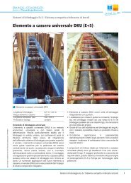
Single slide rail system EG PV<br />
I<br />
II<br />
III<br />
IV<br />
lM Slide rail<br />
Boogie car<br />
Base panel<br />
Top panel<br />
Module length<br />
lc b<br />
bc hc tpl Single slide-rail EG PV with U-type or rectangular roller unit<br />
Pipe culvert length<br />
Shoring / trench width<br />
Inner width<br />
Pipe culvert height<br />
Thickness<br />
(All dimensions in mm. The details of length of pipe opening l c refer to the rectangular roller unit.)<br />
Usage instruction single slide-rail shoring EG PV Krings<br />
9
Single slide rail system EG PV<br />
Slide rail<br />
Art. No.<br />
156 060<br />
Boogie car<br />
Art. No.<br />
159 280<br />
832 204<br />
Description<br />
EG PV - 4000<br />
Short description<br />
Rectangular boogie car<br />
U-type boogie car<br />
Extension bars <strong>for</strong> SL PV R 2112 x 260<br />
Art. No.<br />
159 810<br />
159 570<br />
159 575<br />
159 690<br />
Short description<br />
Extension bar ZW FL PV - 500x205<br />
Extension bar ZW FL PV - 1000x205<br />
Extension bar ZW FL PV - 1500x205<br />
Extension bar ZW FL PV - 2000x205<br />
Extension bars are available in all lengths on request and can be combined.<br />
Extension bars <strong>for</strong> SL PV U 1700 x 450<br />
Art. No.<br />
831 500<br />
831 510<br />
831 520<br />
831 530<br />
831 540<br />
Short description<br />
Extension bar HEA 450<br />
Extension bar HEA 450<br />
Extension bar HEA 450<br />
Extension bar HEA 450<br />
Extension bar HEA 450<br />
Shoring widths <strong>for</strong> SL PV R 2112 x 260<br />
Length<br />
extension bar<br />
[m]<br />
0,000<br />
0,500<br />
1,000<br />
1,500<br />
2,000<br />
Shoring panel<br />
KRI 2,00 - 3,50<br />
b c [m]<br />
0,540<br />
1,040<br />
1,540<br />
2,040<br />
2,540<br />
b [m]<br />
0,760<br />
1,260<br />
1,760<br />
2,260<br />
2,760<br />
Panels without intermediate element<br />
Shoring panel<br />
KRU 2,00 - 3,50<br />
b c [m]<br />
0,465<br />
0,965<br />
1,465<br />
1,965<br />
2,465<br />
b [m]<br />
0,685<br />
1,185<br />
1,685<br />
2,185<br />
2,685<br />
Shoring widths <strong>for</strong> SL PV U 1700 x 450<br />
Lenth<br />
extension bar<br />
[m]<br />
0,000<br />
0,275<br />
0,550<br />
1,100<br />
1,650<br />
2,200<br />
Shoring panel<br />
KRI 2,00 - 3,50<br />
b c [m]<br />
0,995<br />
1,270<br />
1,545<br />
2,095<br />
2,645<br />
3,195<br />
b [m]<br />
1,215<br />
1,490<br />
1,765<br />
2,315<br />
2,865<br />
3,415<br />
Panels without intermediate element<br />
Shoring panel<br />
KRU 2,00 - 3,50<br />
b c [m]<br />
0,925<br />
1,200<br />
1,475<br />
2,025<br />
2,575<br />
3,125<br />
b [m]<br />
1,145<br />
1,420<br />
1,695<br />
2,245<br />
2,795<br />
3,345<br />
Shoring panel<br />
KRI 4,00 - 5,00<br />
b c [m]<br />
0,540<br />
1,040<br />
1,540<br />
2,040<br />
2,540<br />
b [m]<br />
0,790<br />
1,290<br />
1,790<br />
2,290<br />
2,790<br />
Shoring panel<br />
KRI 4,00 - 5,00<br />
b c [m]<br />
0,995<br />
1,270<br />
1,545<br />
2,095<br />
2,645<br />
3,195<br />
b [m]<br />
1,245<br />
1,520<br />
1,795<br />
2,345<br />
2,895<br />
3,445<br />
10 Usage instruction single slide-rail shoring EG PV Krings<br />
Description<br />
SL PV R 2112 x 260<br />
SL PV U 1700 x 450<br />
Shoring panel<br />
KRU 4,00 - 5,00<br />
b c [m]<br />
0,435<br />
0,935<br />
1,435<br />
1,935<br />
2,435<br />
b [m]<br />
0,685<br />
1,185<br />
1,685<br />
2,185<br />
2,685<br />
Shoring panel<br />
KRU 4,00 - 5,00<br />
b c [m]<br />
0,895<br />
1,170<br />
1,445<br />
1,995<br />
2,545<br />
3,095<br />
b [m]<br />
1,145<br />
1,420<br />
1,695<br />
2,245<br />
2,795<br />
3,345<br />
Shoring panel<br />
KRI 6,00 - 7,00<br />
b c [m]<br />
0,405<br />
0,905<br />
1,405<br />
1,905<br />
2,405<br />
b [m]<br />
0,705<br />
1,205<br />
1,705<br />
2,205<br />
2,705<br />
Shoring panel<br />
KRI 6,00 - 7,00<br />
b c [m]<br />
0,865<br />
1,140<br />
1,415<br />
1,965<br />
2,515<br />
3,065<br />
b [m]<br />
1,165<br />
1,440<br />
1,715<br />
2,265<br />
2,815<br />
3,365<br />
l [m]<br />
4,00<br />
l [m]<br />
0,500<br />
1,000<br />
1,500<br />
2,000<br />
l [m]<br />
0,275<br />
0,550<br />
1,100<br />
1,650<br />
2,200<br />
Shoring panel<br />
KRA 6,00 - 7,00<br />
b c [m]<br />
0,520<br />
1,020<br />
1,520<br />
2,020<br />
2,520<br />
b [m]<br />
0,820<br />
1,320<br />
1,820<br />
2,320<br />
2,820<br />
Shoring panel<br />
KRA 6,00 - 7,00<br />
b c [m]<br />
0,975<br />
1,250<br />
1,525<br />
2,075<br />
2,625<br />
3,175<br />
b [m]<br />
1,275<br />
1,550<br />
1,825<br />
2,375<br />
2,925<br />
3,475<br />
G [kg]<br />
489,0<br />
G [kg]<br />
171,4<br />
450,0<br />
G [kg]<br />
24,9<br />
52,0<br />
72,0<br />
78,0<br />
G [kg]<br />
95,0<br />
130,0<br />
207,0<br />
286,0<br />
362,0<br />
Technical contents are subject to change. Publishing date 29/01/2010
Technical contents are subject to change. Publishing date 29/01/2010<br />
Single slide rail system EG PV<br />
Accessories / Spares<br />
Art. No.<br />
842 753<br />
842 754<br />
336 960<br />
159 030<br />
139 070<br />
139 080<br />
842 099<br />
842 100<br />
139 045<br />
IA 0150F<br />
IA 0210F<br />
139 035<br />
IB 0470F<br />
IB 0614F<br />
139 050<br />
139 110<br />
139 120<br />
l<br />
lM lc b<br />
Short description<br />
Adapter <strong>for</strong> DKU piling frame corner shoring<br />
Adapter <strong>for</strong> DKU piling frame EG PV ML 2.77 + 4.27<br />
Bearing claw<br />
Bolt 110 x 80<br />
Chain sling connection, 4-leg, 2300 x 13<br />
Chain sling connection, 4-leg, 2800 x 13<br />
DKU piling frame guide frame<br />
DKU piling frame guide frame<br />
Nut M 16<br />
Nut M 24<br />
Nut M 36<br />
Screw M 16 x 70<br />
Screw M 24 x 80<br />
Screw M 36 x 80<br />
Washer 17<br />
Wire rope 4-legs, 1800 x 20<br />
Wire rope 4-legs, 2800 x 20<br />
Length<br />
Module length<br />
Pipe culvert length<br />
Shoring / trench width<br />
bc G<br />
d<br />
l [m]<br />
0,110<br />
2,30<br />
2,80<br />
2,27<br />
3,81<br />
1,80<br />
2,80<br />
Inner width<br />
Weight<br />
Diameter<br />
G [kg]<br />
94,0<br />
60,0<br />
40,0<br />
2,6<br />
45,0<br />
57,0<br />
105,0<br />
175,0<br />
0,1<br />
0,1<br />
0,4<br />
0,1<br />
0,4<br />
1,0<br />
0,01<br />
40,0<br />
46,0<br />
d [m]<br />
0,080<br />
Standard<br />
DIN 6915<br />
DIN 934<br />
DIN 934<br />
DIN 6914<br />
DIN 933<br />
DIN 933<br />
DIN 6916<br />
Usage instruction single slide-rail shoring EG PV Krings<br />
11
.<br />
Assembly instructions <strong>for</strong> the frame <strong>for</strong> single slide-rail shoring<br />
EG PV and single slide-rail shoring EG PV with piling frame KKP<br />
KD6 CPS<br />
1. System overview <strong>for</strong> the guide frame<br />
2. Fitting the slide<br />
3. Pinning the slide<br />
X<br />
A-A<br />
12 Usage instruction single slide-rail shoring EG PV Krings<br />
X<br />
(1) Two slide rails EG PV<br />
(2) Two roller units<br />
(3) Two spacer bars<br />
By using lifting gear and a suitable sling (GS-approved),<br />
slide a roller unit into each of the slide rails EG PV.<br />
Secure the roller unit in the slide rail EG PV by inserting the<br />
pins (4) and (5) into the envisaged holes (see detail X) at<br />
the top and bottom of the rail, above and below the roller<br />
unit. After insertion the pin must be turned through 180°.<br />
Technical contents are subject to change. Publishing date 29/01/2010
.<br />
Technical contents are subject to change. Publishing date 29/01/2010<br />
4. Fitting the spacer bars<br />
5. Assembly of the complete guide frame<br />
The pre-assembled combinations of spacer bars (3)<br />
required <strong>for</strong> the desired trench width are aligned with the<br />
bolting plates of the roller units and bolted with the required<br />
number of bolts as per piece list. To facilitate alignment of<br />
the spacer bars during the next assembly step, the bolts<br />
are only loosely fastened.<br />
The slide rail EG PV prefitted with the roller units and<br />
spacer bars is pivoted over the second soldier so that the<br />
roller units and spacer bars can be bolted together.<br />
After assembly, the guide frame is laid flat on the<br />
ground.<br />
All screw joints must be tightened firmly.<br />
For large trench widths, the complete guide frame should be assembled on its side. To this end, the two roller units inserted<br />
into the slide rails must be prefitted with spacer bars of about the same length. After preassembly, the two slide rails are laid<br />
side by side on the ground so that the spacer bars can be bolted together.<br />
To create a shoring unit, two fully assembled guide frames are required. For each further shoring unit, an additional guide<br />
frame must be provided.<br />
Usage instruction single slide-rail shoring EG PV Krings<br />
13
.<br />
Adapting the U-type roller unit <strong>for</strong> <strong>use</strong> in single slide-rail shoring<br />
EG PV and in single slide-rail shoring EG PV with piling frame KKP<br />
KD6 CPS<br />
1. Removing the spacers<br />
So that the U-type roller unit can be <strong>use</strong>d in the single slide rail EG PV, it is necessary to remove the bolts and nuts on the<br />
tension anchor (1 and 2).<br />
For this you need a 17 mm wrench (open-ended or ring-type).<br />
2. Sliding in the roller unit<br />
The roller unit can now be slid into the single slide rail in the manner shown.<br />
14 Usage instruction single slide-rail shoring EG PV Krings<br />
1<br />
2<br />
Technical contents are subject to change. Publishing date 29/01/2010
.<br />
Technical contents are subject to change. Publishing date 29/01/2010<br />
Installation instructions <strong>for</strong> single slide-rail shoring EG PV<br />
1. Placing the first guide frame<br />
2. Inserting the base panels<br />
After measurement of the trench line, the initial layer of soil<br />
is excavated <strong>for</strong> the first shoring unit in accordance with the<br />
project management’s instructions.<br />
Width: Required clear trench width + approx. 0.4 m<br />
Length: Module length + approx. 0.45 m (or inner panel<br />
length + approx. 0.7 m)<br />
Using lifting gear and a suitable sling (GS-approved), the<br />
first guide frame is placed in the centre of the trench axis<br />
and at right angles to the trench line. The bottom end of the<br />
roller unit rests on the pin inserted in the slide rail and its<br />
upward motion is limited by a pin in the guide frame (see<br />
assembly instructions). If necessary, the frame can be<br />
locked plumb (e.g. with the aid of a second set of lifting<br />
gear).<br />
Using lifting gear, the base panels are inserted from above<br />
into the slide rail profile. After insertion, the shoring panels<br />
are lowered to the bottom of the trench.<br />
Be<strong>for</strong>e lowering the slide rail frame, always remove the pins<br />
which may have been fitted to set a different vertical pipe<br />
clearance.<br />
Usage instruction single slide-rail shoring EG PV Krings<br />
15
.<br />
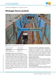
3. Aligning the shoring panels<br />
Diagonale<br />
lichte Breite<br />
lichte Breite<br />
Diagonale<br />
4. Placing the second guide frame<br />
16 Usage instruction single slide-rail shoring EG PV Krings<br />
The first shoring unit has to be precisely aligned so that the<br />
shoring runs parallel with the trench axis. It is important<br />
here that the horizontal clearance between the shoring<br />
panels is the same at both panel ends; and that the two<br />
diagonal axes of the shoring unit are the same length.<br />
lichte Weite = Clear width<br />
Diagonale = Diagonal<br />
The second frame is guided over the exposed guide<br />
profiles of the base panels and pushed down to the bottom<br />
of the trench.<br />
After placement, the shoring unit should again be aligned<br />
(as described in step 3) in order to facilitate the installation<br />
and removal of subsequent shoring units.<br />
The cavity between the soil and shoring panel must be<br />
backfilled and compacted.<br />
Technical contents are subject to change. Publishing date 29/01/2010
.<br />
Technical contents are subject to change. Publishing date 29/01/2010<br />
5. Lowering the shoring unit<br />
6. Inserting the top panels<br />
T<br />
B<br />
7. Lowering to the final depth<br />
5<br />
6<br />
Be<strong>for</strong>e the lowering process proper, the soil beneath the<br />
shoring panels is excavated in accordance with the project<br />
management’s instructions. The slide rails, shoring panels<br />
and roller units are pressed down in turn, with special <strong>use</strong><br />
being made of protective rails <strong>for</strong> the shoring panels.<br />
The shoring components must be pressed and on no<br />
account struck or hammered.<br />
When lowering the system, make absolutely sure that the<br />
roller units are positioned vertically to provide the required<br />
structural strength (pay attention to length of cantilever).<br />
.<br />
Depending on the required trench depth, the top panels (T)<br />
are inserted in the rail guides when the base panels (B)<br />
have been lowered to the trench bottom.<br />
The base and top panels must be joined together with bolts<br />
(5) and spring pins (6).<br />
When the top panels have been inserted, the shoring unit is<br />
lowered to its final depth with advance soil excavation in<br />
accordance with the instructions of the project management<br />
on site.<br />
Here, again, the roller unit must be vertically positioned to<br />
provide the necessary structural strength (pay attention to<br />
length of cantilever).<br />
Usage instruction single slide-rail shoring EG PV Krings<br />
17
.<br />
8. Installing the next shoring unit<br />
9. Pipe laying<br />
18 Usage instruction single slide-rail shoring EG PV Krings<br />
The next shoring unit is installed as soon as the preceding<br />
unit has been fully lowered to the bottom of the trench and<br />
the roller units are vertically positioned and fixed in order to<br />
provide the required structural strength. Installation is<br />
carried in the manner described in steps 1 to 7.<br />
Subsequent units are aligned with the precisely installed<br />
first unit. The clear trench width and length of diagonal<br />
(step 3) should be checked <strong>for</strong> each subsequent unit when<br />
installing the shoring panels.<br />
Once the complete desired train of shoring has been fully<br />
lowered to the bottom of the trench, pipe laying can start.<br />
The roller units must be vertically positioned and fixed with<br />
pins or chains in order to provide the required structural<br />
strength.<br />
Technical contents are subject to change. Publishing date 29/01/2010
.<br />
Technical contents are subject to change. Publishing date 29/01/2010<br />
<strong>Instructions</strong> <strong>for</strong> removing single slide-rail shoring EG PV<br />
Removal, backfilling and compacting<br />
At the end of pipe-laying work, the shoring is removed with<br />
layer-by-layer backfilling and compacting. To this end, the<br />
shoring is extracted step-by-step in accordance with the<br />
instructions of the project manager on site and with the<br />
expert's specifications and the backfilling material returned<br />
to the trench is compacted against the existing soil.<br />
Slings must only be attached to the holes provided.<br />
Support <strong>for</strong> base of soldier/cast-in-place concrete<br />
1. Inserting the shoring<br />
When laying pipes of large diameter or building cast-in-<br />
place concrete drains/sewers, additional support <strong>for</strong> the<br />
guide frames at the base of the soldiers is often needed <strong>for</strong><br />
reasons of stability.<br />
To this end, the shoring is initially installed in accordance<br />
with the installation instructions (see "Installation<br />
instructions <strong>for</strong> single slide-rail shoring EG PV", steps 1 to<br />
9) and the bottom of the trench prepared in accordance<br />
with requirements.<br />
Any support <strong>for</strong> the base of the soldiers depends on the<br />
calculations of structural strength and takes the <strong>for</strong>m of a<br />
spar of steel or rein<strong>for</strong>ced concrete. In the case of cast-in-<br />
place concrete drains/sewers, the bed carrying the drain/-<br />
sewer can be <strong>use</strong>d as the support <strong>for</strong> the base of the<br />
soldier.<br />
The support <strong>for</strong> the base of the soldier should have a<br />
contact surface sufficiently large <strong>for</strong> the soldier.<br />
Proof of structural strength should be provided <strong>for</strong> the load-<br />
bearing capacity of the support <strong>for</strong> the base of the soldier.<br />
Usage instruction single slide-rail shoring EG PV Krings<br />
19
.<br />
2. Creating support <strong>for</strong> the base of the soldier<br />
3. Removing the shoring unit<br />
20 Usage instruction single slide-rail shoring EG PV Krings<br />
When support <strong>for</strong> the base of the soldier has been<br />
provided, the roller unit can be raised to the maximum<br />
permitted vertical pipe clearance <strong>for</strong> completion of the cast-<br />
in-place concrete structure. In this position, the roller unit<br />
must be secured with chains or pins.<br />
During raising, the roller unit must always be<br />
prevented from sliding out of the top of the soldier (<strong>for</strong><br />
pin, see "Assembly instructions <strong>for</strong> the guide frame <strong>for</strong><br />
single slide-rail shoring EG PV", step 3).<br />
If the shoring is also to serve as <strong>for</strong>mwork <strong>for</strong> a cast-in-<br />
place concrete structure, the open guides of the roller units<br />
in the slide rails must be sealed with sealing panels. In this<br />
way, a continuous smooth surface is created together with<br />
the KRU shoring panels. An intermediate layer (e.g. rigid<br />
foam panels, plastic sheeting) must always be inserted<br />
between the shoring and the cast-in-place wall in order to<br />
ensure smooth removal<br />
.<br />
When the concrete walls have set, the shoring is removed<br />
in the way described in "<strong>Instructions</strong> <strong>for</strong> removing single<br />
slide-rail shoring EG PV".<br />
Technical contents are subject to change. Publishing date 29/01/2010
.<br />
Technical contents are subject to change. Publishing date 29/01/2010<br />
Installation instructions <strong>for</strong> single slide-rail shoring EG PV with<br />
piling frame KKP KD6 CPS<br />
1. General remarks<br />
For single slide-rail shoring EG PV with piling frame KKP KD6 CPS, sheet piles are guided in piling frame elements. To<br />
make allowance <strong>for</strong> pipes/cables crossing the trench, particularly in densely built-up inner-city areas, openings can thus be<br />
flexibly provided in the supported and secured trench walls.<br />
2. Placing the first guide frame<br />
3. Placing the piling frame element<br />
After measurement of the trench line, the initial layer of soil<br />
is excavated <strong>for</strong> the first shoring unit in accordance with the<br />
project management’s instructions.<br />
Width: Required clear trench width + approx. 0.8 m<br />
Length: Module length + approx. 0.45 m<br />
Using lifting gear and a suitable sling (GS-approved), the<br />
first guide frame is placed in the centre of the trench axis<br />
and at right angles to the trench line. The bottom end of the<br />
roller unit rests on the pin secured in the slide rail and its<br />
upward motion is limited by a pin in the guide frame (see<br />
assembly instructions). If necessary, the frame can be<br />
locked plumb (e.g. with the aid of a second set of lifting<br />
gear).<br />
The piling frame element is pivoted from above into the<br />
slide rail.<br />
Be<strong>for</strong>e lowering the slide rail frame, always remove the<br />
bottom pin if it has been fitted to set a different vertical pipe<br />
clearance.<br />
Usage instruction single slide-rail shoring EG PV Krings<br />
21
.<br />
4. Aligning the piling frame element<br />
lichte Weite<br />
Diagonale<br />
Diagonale<br />
lichte Weite<br />
5. Placing the second guide frame<br />
22 Usage instruction single slide-rail shoring EG PV Krings<br />
The first shoring unit has to be precisely aligned so that the<br />
shoring runs parallel with the trench axis. It is important<br />
here that the horizontal clearance between the piling frame<br />
element is the same at both ends; and that the two<br />
diagonal axes of the shoring unit are the same length.<br />
lichte Weite = Clear width<br />
Diagonale = Diagonal<br />
Using lifting gear, the second frame is guided over the<br />
exposed guide profiles of the piling frame element and<br />
lowered to the bottom of the trench. On unstable soils in<br />
particular, chains must be <strong>use</strong>d to prevent the piling frame<br />
elements from sinking.<br />
After placement, the shoring unit should again be aligned in<br />
order to facilitate the installation and removal of subsequent<br />
shoring units.<br />
The cavity between the soil and piling frame element must<br />
be backfilled and compacted.<br />
Technical contents are subject to change. Publishing date 29/01/2010
.<br />
Technical contents are subject to change. Publishing date 29/01/2010<br />
6. Inserting the sheet piles and lowering the shoring unit<br />
7. Inserting Krings waling girders<br />
A<br />
A - A<br />
A<br />
When the sheet piles have been inserted in the two<br />
opposite piling frame elements, further soil can be<br />
excavated beneath the slide rails and sheet piles in<br />
accordance with the instructions of project management on<br />
site. The sheet piles and slide rails are pushed or pressed<br />
down in turn. The shoring components must be pressed<br />
and on no account struck or hammered.<br />
The piling frame elements must be fixed in position.<br />
When lowering the shoring system, make absolutely<br />
sure that the roller units are positioned vertically to<br />
provide the required structural strength (pay attention<br />
to length of cantilever).<br />
After exposure of the pipe/cable crossing the trench, Krings<br />
waling girders must be attached on either side of the<br />
shoring in order to provide the required structural strength.<br />
One end of the waling girders is pushed into the open guide<br />
of a slide rail. The slide rail at the other end of the waling<br />
girders must not be lowered to the bottom of the trench<br />
(see adjacent figure). Only at the next stage (step 8) is this<br />
pair of slide rails pushed via the guide profile of the waling<br />
girders resting on the bottom of the trench.<br />
Fitting the waling girders reduces the cantilever length of<br />
the sheet piles and prevents the sheet piles being inwardly<br />
deflected into the trench.<br />
Usage instruction single slide-rail shoring EG PV Krings<br />
23
.<br />
8. Pressing the pair of slide rails and lowering the shoring<br />
9. Lowering to the final depth<br />
24 Usage instruction single slide-rail shoring EG PV Krings<br />
When the pair of slide rails has been lowered, both ends of<br />
the waling girders rest in the open guides of the slide rails.<br />
The sheet piles are now pressed down. Make sure that the<br />
waling girders and sheet piles are pressed tightly together.<br />
If the waling girders have to be lowered, they must be<br />
prevented from accidentally sliding out of the slide rails,<br />
e.g. with a chain.<br />
With advance soil excavation in accordance with the<br />
instructions of the project management on site, the shoring<br />
unit is lowered to its final depth. Chains (GS-approved) are<br />
<strong>use</strong>d to lock the waling girders at the horizontal level<br />
demanded <strong>for</strong> reasons of stability. Here, again, the roller<br />
unit must be vertically positioned to provide the necessary<br />
structural strength (pay attention to length of cantilever).<br />
Technical contents are subject to change. Publishing date 29/01/2010
.<br />
Technical contents are subject to change. Publishing date 29/01/2010<br />
10. Installing the next shoring unit<br />
11. Pipe laying<br />
The next shoring unit is installed as soon as the preceding<br />
unit has been fully lowered to the bottom of the trench and<br />
the roller units are vertically positioned and fixed in order to<br />
provide the required structural strength. Installation is<br />
carried in the manner described in steps 1 to 9.<br />
Subsequent units are aligned with the precisely installed<br />
first unit. The clear trench width and length of diagonal<br />
(step 4) should be checked <strong>for</strong> each subsequent unit when<br />
installing the piling frame elements.<br />
Once the complete desired train of shoring has been fully<br />
lowered to the bottom of the trench, pipe laying can start.<br />
The roller units must be vertically positioned in order to<br />
provide the required structural strength and fixed with pins<br />
or chains.<br />
For removal, see the instructions given in the "<strong>Instructions</strong><br />
<strong>for</strong> removing single slide-rail linear shoring EG PV".<br />
Usage instruction single slide-rail shoring EG PV Krings<br />
25
.<br />
12. Installation example<br />
There is no problem combining "single slide-rail shoring EG PV" with "single slide-rail shoring EG PV with piling frame KKP<br />
KD6 CPS".<br />
26 Usage instruction single slide-rail shoring EG PV Krings<br />
Technical contents are subject to change. Publishing date 29/01/2010
Technical contents are subject to change. Publishing date 29/01/2010<br />
Technical data sheet single slide-rail corner shoring<br />
Usage instruction single slide-rail shoring EG PV Krings<br />
27
Corner post EG Eck / DG Eck<br />
I<br />
II<br />
III<br />
Corner post<br />
Base panel -outside-<br />
Base panel -inside-<br />
Corner post EG Eck / DG Eck<br />
(All dimensions in mm)<br />
28 Usage instruction single slide-rail shoring EG PV Krings<br />
b<br />
bc Shoring / pit width<br />
Inner width<br />
Technical contents are subject to change. Publishing date 29/01/2010
Technical contents are subject to change. Publishing date 29/01/2010<br />
Corner post EG Eck / DG Eck<br />
Slide rail<br />
Art. No.<br />
156 030<br />
157 050<br />
157 060<br />
157 070<br />
157 010<br />
Short description<br />
Single corner rail<br />
Double corner rail<br />
Double corner rail<br />
Double corner rail<br />
Double corner extension rail<br />
Shoring widths <strong>for</strong> DG corner<br />
Shoring panel<br />
Length [m]<br />
2,00<br />
2,50<br />
3,00<br />
3,50<br />
4,00<br />
4,50<br />
5,00<br />
6,00<br />
7,00<br />
KRU<br />
b c [m]<br />
2,110<br />
2,610<br />
3,110<br />
3,610<br />
4,110<br />
4,610<br />
5,110<br />
6,015<br />
7,015<br />
Accessories / Spares<br />
b [m]<br />
2,620<br />
3,120<br />
3,620<br />
4,120<br />
4,660<br />
5,160<br />
5,660<br />
6,630<br />
7,630<br />
see Single slide rail system EG PV (page 11)<br />
l<br />
b<br />
Length<br />
Shoring / trench width<br />
KRI<br />
b c [m]<br />
2,175<br />
2,675<br />
3,175<br />
3,675<br />
4,175<br />
4,675<br />
5,175<br />
6,015<br />
7,015<br />
Description<br />
EG ECK - 3500<br />
DG ECK - 4500<br />
DG ECK - 5000<br />
DG ECK - 5500<br />
DG A ECK - 2000<br />
b [m]<br />
2,685<br />
3,185<br />
3,685<br />
4,185<br />
4,725<br />
5,225<br />
5,725<br />
6,730<br />
7,730<br />
bc G<br />
Inner width<br />
Weight<br />
l [m]<br />
3,50<br />
4,50<br />
5,00<br />
5,50<br />
2,00<br />
G [kg]<br />
195,0<br />
517,0<br />
575,0<br />
624,0<br />
244,0<br />
Usage instruction single slide-rail shoring EG PV Krings<br />
29
.<br />
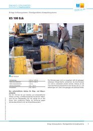
Installation instructions <strong>for</strong> single slide-rail corner shoring<br />
1. General remarks<br />
Single slide-rail corner shoring is a special shoring method <strong>for</strong> shaft structures as well as <strong>for</strong> trench shoring with combined<br />
trench-end units. If <strong>use</strong>d <strong>for</strong> shaft shoring, special bracing systems can be omitted. All the <strong>for</strong>ces are then discharged via<br />
the shoring panels. With the appropriate guide rails, it can take the <strong>for</strong>m of single or double slide-rail shoring.<br />
By using different panel lengths in pairs, it is possible to realize rectangular pits of various sizes.<br />
2. Installing the base panels<br />
3. Installing the corner rail<br />
30 Usage instruction single slide-rail shoring EG PV Krings<br />
After measurement of the pit, the initial layer of soil is<br />
excavated <strong>for</strong> the shaft to match the panel lengths <strong>use</strong>d.<br />
The project management’s instructions and the relevant<br />
standards must be observed.<br />
The first shoring panel is lifted with lifting gear and a<br />
suitable sling (GS-approved) into the pit and fixed.<br />
By using a second set of lifting gear, the corner slide rail<br />
can now be slotted in from above.<br />
Technical contents are subject to change. Publishing date 29/01/2010
.<br />
Technical contents are subject to change. Publishing date 29/01/2010<br />
4. Installing further elements<br />
5. Aligning the shoring<br />
6. Lowering the shoring<br />
All further elements must be installed in the manner already<br />
described.<br />
So that the last wall of shoring can also be installed without<br />
difficulty, the shoring has to be properly aligned. To this<br />
end, it is important here that the horizontal clearance<br />
between the shoring panels is the same at both panel ends;<br />
and that the two diagonal axes of the shoring unit are the<br />
same length.<br />
When the fourth base panel has been installed, the<br />
rectangularity of the shoring must again be checked. Then<br />
the cavity between the soil and shoring panel must be<br />
backfilled and compacted.<br />
Be<strong>for</strong>e the lowering process proper, the soil beneath the<br />
shoring panels and slide rails is excavated in accordance<br />
with the project management’s instructions. The slide rails<br />
and shoring panels are pressed down in turn, with special<br />
<strong>use</strong> being made of pressure beams <strong>for</strong> the shoring panels.<br />
The shoring components must be pressed and on no<br />
account struck or hammered.<br />
Usage instruction single slide-rail shoring EG PV Krings<br />
31
.<br />
7. Installing the inner top panels<br />
8. Installation example of a trench-end unit<br />
Depending on the required trench depth, the inner top<br />
panels are inserted in the slide rail guides when the inner<br />
base panels have been lowered to the provisional trench<br />
bottom.<br />
The base and top panels must be joined together with pins.<br />
There is no problem combining "single slide-rail shoring EG PV" with "slide-rail corner shoring". This way it is possible to<br />
continuously shore pits and trenches.<br />
32 Usage instruction single slide-rail shoring EG PV Krings<br />
Technical contents are subject to change. Publishing date 29/01/2010
.<br />
Imprint<br />
Editor<br />
ThyssenKrupp Ba<strong>use</strong>rvice GmbH<br />
Ottostraße 30<br />
41836 Hückelhoven-Baal<br />
GERMANY<br />
Phone: +49 2433 453-0<br />
Fax: +49 2433 453-100<br />
E-mail: ES-Krings@thyssenkrupp.com<br />
www.es-verbau.com<br />
Composition and Production<br />
visaplan GmbH<br />
www.visaplan.com<br />
indivis GbR<br />
www.indivis.de<br />
Technical contents are subject to change.<br />
www.es-verbau.com<br />
33