Krings Instructions for use - Emunds + Staudinger GmbH
Krings Instructions for use - Emunds + Staudinger GmbH
Krings Instructions for use - Emunds + Staudinger GmbH

You also want an ePaper? Increase the reach of your titles
YUMPU automatically turns print PDFs into web optimized ePapers that Google loves.
www.es-verbau.com<br />
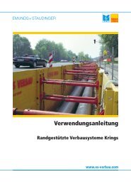
Using instruction<br />
ThyssenKrupp Ba<strong>use</strong>rvice<br />
Pipe puller type SZ 10
Technical In<strong>for</strong>mation <strong>Krings</strong> Verbau<br />
Pipe puller<br />
Type: ______________________________________<br />
Year of construction ______________________________________<br />
Serial No. ______________________________________<br />
Order No. ______________________________________<br />
Recipient ______________________________________<br />
2 Using instruction pipe puller<br />
Technical contents are subject to change. Publishing date 29/01/2010
Contents<br />
1. Preface 5<br />
2. Introduction and general in<strong>for</strong>mation 6<br />
2.1 Introduction 6<br />
2.2 Liability and warranty 6<br />
2.3 General in<strong>for</strong>mation on this manual and how to <strong>use</strong> it 7<br />
2.4 Key to symbols (pictograms) 7<br />
3. Handling, set-up and assembly 8<br />
3.1 General in<strong>for</strong>mation 8<br />
3.2 Handling the pipe puller 8<br />
3.3 Preparing the pipe puller <strong>for</strong> operation 9<br />
4. Functions, overview of subassemblies and technical data 10<br />
4.1 Illustration of the pipe puller with its subassemblies and extra equipment 10<br />
4.2 How the pipe puller works 11<br />
4.3 Definition of intended <strong>use</strong> 12<br />
4.4 Technical data 12<br />
4.5 Electrical circuit diagram 13<br />
5. Safety instructions 14<br />
5.1 General in<strong>for</strong>mation 14<br />
5.2 Special safety instructions 14<br />
6. Operating and control elements and their purpose 16<br />
6.1 General in<strong>for</strong>mation 16<br />
6.2 Functions of the control elements on the control panel 16<br />
6.3 Control element <strong>for</strong> hydraulic pressure indication (manometer) 16<br />
7. Initial operation, operation and supervision 17<br />
7.1 General in<strong>for</strong>mation 17<br />
7.2 Initial operation 18<br />
7.3 Operation 18<br />
7.4 Supervision 20<br />
3 Using instruction pipe puller<br />
Technical contents are subject to change. Publishing date 29/01/2010
Contents<br />
8. Malfunctions, ca<strong>use</strong>s and remedies 20<br />
8.1 General in<strong>for</strong>mation 20<br />
8.2 Malfunctions 20<br />
9. Maintenance and servicing 21<br />
9.1 General in<strong>for</strong>mation 21<br />
9.2 Overview of maintenance 22<br />
9.3 Maintenance as required 23<br />
9.4 Daily maintenance 25<br />
9.5 Monthly maintenance 26<br />
9.6 Annual maintenance 27<br />
10. Appendix 27<br />
10.1 Declaration relating to the manual 27<br />
Mention d’impression 28<br />
4 Using instruction pipe puller<br />
Technical contents are subject to change. Publishing date 29/01/2010
1. Preface<br />
Subject to change.<br />
All rights to this publication are reserved, and particularly the rights of duplication, dissemination and translation.<br />
No part of this publication may be reproduced (by photocopy, microfiche or any other method) or duplicated or<br />
disseminated by electronic means in any way without the prior written consent of ThyssenKrupp Ba<strong>use</strong>rvice<br />
<strong>GmbH</strong>.<br />
Print legend<br />
5 Using instruction pipe puller<br />
4th edition March 1995<br />
We advise you to keep the <strong>use</strong>r’s manual <strong>for</strong> the pipe puller in a suitable place so that you can consult it directly<br />
at any time.<br />
There<strong>for</strong>e store the manual carefully as you may need it later <strong>for</strong> the following purposes:<br />
- When moving the pipe puller to a new site<br />
- When modifying machine components<br />
- For the operation, maintenance and checking of the pipe puller<br />
- For training purposes<br />
- For independent study.<br />
Technical contents are subject to change. Publishing date 29/01/2010
2. Introduction and general in<strong>for</strong>mation<br />
2.1 Introduction<br />
This manual is intended as an aid to staff responsible <strong>for</strong> operation, supervision and maintenance of the pipe puller. It contains<br />
a detailed description of the various operating steps, in<strong>for</strong>mation on initial and subsequent operation of all the units and<br />
equipment belonging to the pipe puller, and instructions on maintenance and servicing in so far as operating staff are<br />
responsible <strong>for</strong> this.<br />
Malfunctions that staff are unable to remedy locally should be reported to our After-Sales Service <strong>for</strong> assistance.<br />
ThyssenKrupp Ba<strong>use</strong>rvice <strong>GmbH</strong><br />
Ottostr. 30<br />
41836 Hückelhoven<br />
Germany<br />
Phone 02433 453-0<br />
Fax 02433 453-100<br />
E-Mail es-krings@thyssenkrupp.com<br />
2.2 Liability and warranty<br />
All details and instructions concerning the operation and maintenance of the machine are given to the best of our knowledge on<br />
the basis of our experience and findings to date.<br />
We are liable <strong>for</strong> any errors or omissions on exclusion of all further claims in accordance with the warranty obligations entered<br />
into in the main contract. Claims <strong>for</strong> any further compensation <strong>for</strong> damages on whatever legal grounds are excluded.<br />
The manual is also translated to the best of our knowledge. We cannot accept any liability <strong>for</strong> incorrect translation, and not even<br />
if the translation was carried out by us or on our behalf. The German text alone is authoritative. We would be happy to supply it<br />
on request.<br />
This manual must not be passed on to third parties. Such acts are subject to compensation <strong>for</strong> damages.<br />
i<br />
Liability and warranty claims are excluded:<br />
- if the in<strong>for</strong>mation and instructions contained in the manual are disregarded,<br />
- if the pipe puller and the associated equipment are incorrectly operated or their handling deviates from the<br />
procedure described.<br />
- if the pipe puller is <strong>use</strong>d <strong>for</strong> purposes <strong>for</strong> which it is not intended,<br />
- if protective devices are not <strong>use</strong>d or disabled,<br />
- if functional modifications of any kind are carried out without our written consent,<br />
- if the relevant safety instructions are disregarded (see the chapter on safety in this manual),<br />
- if the pipe puller and the associated equipment are maintained incorrectly (or at incorrect intervals), which also<br />
includes the <strong>use</strong> of the prescribed replacement parts.<br />
Batteries, hydraulic hoses, electric cables and slings are wearing parts and are not covered by the manufacturer’s<br />
warranty.<br />
Only the original or equivalent parts approved by the manufacturer are to be <strong>use</strong>d as replacement or spare parts.<br />
Liability and warranty claims are excluded in the event of non-observance of this point.<br />
6 Using instruction pipe puller<br />
Technical contents are subject to change. Publishing date 29/01/2010
2.3 General in<strong>for</strong>mation on this manual and how to <strong>use</strong> it<br />
1. During handover, the manufacturer explained how to operate and maintain the pipe puller. However, be<strong>for</strong>e you<br />
<strong>use</strong> the machine, please read this manual carefully. The specially marked safety instructions must always be<br />
observed!<br />
2. Do not put this manual unread to one side, even if you have already operated such a machine or one of a similar<br />
kind.<br />
3. The supplied pipe puller is designed and manufactured in accordance with the KRINGS-VERBAU <strong>GmbH</strong><br />
specifications and accident prevention rules. To prevent accidents and to ensure optimum per<strong>for</strong>mance, no<br />
modifications or conversions may be carried out on the pipe puller unless these are explicitly approved by KRINGS-<br />
VERBAU <strong>GmbH</strong>/ThyssenKrupp Ba<strong>use</strong>rvice <strong>GmbH</strong>.<br />
4. Important instructions, such as those relating to safety, are marked with appropriate symbols.<br />
5. Comply with these instructions in order to prevent accidents, damage to the pipe puller and personal injury (<strong>for</strong> an<br />
explanation of the symbols, see next section).<br />
6. The operator is obliged to observe the relevant environmental protection provisions and his duties concerning the<br />
disposal of wastes (hydraulic fluid change, battery acid, cleaning agents etc.).<br />
7. This manual <strong>use</strong>s the internationally standardized SI units of measurement.<br />
8. All details in brackets in the following refer to more detailed explanations on the pages named.<br />
9. The passages marked with asterisks (*) refer to optional extras that have supplementary or extended functions.<br />
These passages may or may not be relevant, depending on the scale of your order.<br />
2.4 Key to symbols<br />
i<br />
Danger area<br />
7 Using instruction pipe puller<br />
Danger: Suspended loads<br />
In<strong>for</strong>mation<br />
Danger: High voltage!<br />
Danger: Obstacles. Watch your step.<br />
Technical contents are subject to change. Publishing date 29/01/2010
3. Handling, set-up and assembly<br />
3.1 General in<strong>for</strong>mation<br />
The pipe puller is usually supplied in a sturdy shipping crate. The shipping crate contains the following in accordance with your<br />
order:<br />
- The complete pipe puller with fitted socket clamp, installed 12 V battery and integrated hydraulic control block<br />
- The control cable with connection plug and control panel<br />
- Various connection and small parts.<br />
i<br />
It is advisable to check the entire consignment <strong>for</strong> completeness and any shipment damage immediately on<br />
arrival. This is possible by referring to the delivery note and accompanying papers.<br />
In general, complaints will only be accepted if they are reported to the <strong>for</strong>warding company or ThyssenKrupp<br />
Ba<strong>use</strong>rvice <strong>GmbH</strong> on the day of arrival of the pipe puller.<br />
At its place of <strong>use</strong>, the pipe puller must be handled and prepared <strong>for</strong> initial operation in accordance with the<br />
following instructions.<br />
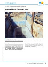
3.2 Handling of the pipe puller<br />
The pipe puller must be brought to its place of <strong>use</strong> by a crane or equivalent lifting gear (excavator) and with a suitable sling, as<br />
shown in the figure below. Proceed as follows:<br />
Only <strong>use</strong> the sling attachment points marked in green. Any rings not marked in green are solely of relevance <strong>for</strong> assembly.<br />
Suspending the pipe puller from these assembly rings risks injury to persons and damage to the machine.<br />
- Tilt the socket clamp (1) onto the pipe carriage (2) so that it engages behind the threaded securing pins on both<br />
sides (3).<br />
- Attach the hooks of the double sling (4) to the ring nut (5) and bar (6). The handling ring is identified by its green<br />
paint. From the upper ring of the double sling, the freely suspended pipe puller can now be moved with suitable<br />
lifting gear.<br />
- Move the pipe puller to its place of <strong>use</strong> and set down.<br />
- During handling, make sure that the pipe puller can never bump against other objects while suspended from the<br />
crane.<br />
- Remove the double sling.<br />
CAUTION<br />
Keep away from the suspended load and out of the excavator’s or crane’s slewing range.<br />
Lifting gear must be suitable <strong>for</strong> the pipe puller weight of approx. 456 kg!<br />
8 Using instruction pipe puller<br />
Technical contents are subject to change. Publishing date 29/01/2010
3.3 Preparing the pipe puller <strong>for</strong> operation<br />
The manufacturer has supplied you with the pipe puller in a prepared state. This means<br />
- with a charged battery (the associated battery charger is not included in the equipment supplied)<br />
- filled with hydraulic fluid.<br />
So that the pipe puller can be put to <strong>use</strong>, only the following steps have to be taken:<br />
- Use the plugs (2) to connect the power supply cable (1)<br />
to the polarized jacks (3) of the power supply unit.<br />
- Insert the plug (4) of the control cable (5) into the pipe<br />
puller socket (6) and secure; alternatively, depending on<br />
conditions, connect the control cable to the cable drum (7)<br />
and plug the latter into the pipe puller socket.<br />
Caution!<br />
The pipe puller may only be operated with the cable drum<br />
connected. Unreel the required length of cable. Keep out of the<br />
danger range of the taut pulling rope when operating the pipe puller.<br />
Keep out of the pipe when operating the KRINGS pipe puller!<br />
- The socket clamp (8) must also be brought into the vertical.<br />
The pipe puller is now ready <strong>for</strong> operation. Its height must be adapted on site to the diameter of the pipe being pulled (see also<br />
section 7).<br />
9 Using instruction pipe puller<br />
Technical contents are subject to change. Publishing date 29/01/2010
4. Functions, subassemblies and technical data<br />
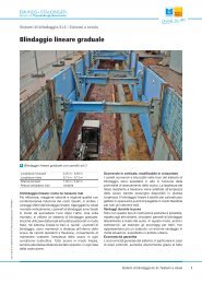
4.1 Illustration of the pipe puller with its subassemblies and extra equipment<br />
Key<br />
1. Pipe carriage with 5 Control panel with cable drum<br />
1.1 undercarriage 5.1 Control cable<br />
5.2 Connection plug<br />
2 Hydraulic pulling cylinder with<br />
2.1 front gripper, 6 Socket clamp with<br />
2.2 rear gripper and 6.1 rotary spindle,<br />
2.3 hydraulic opening cylinder 6.2 support,<br />
6.3 tilt device with<br />
3 Battery case 6.4 threaded securing pins on both sides and<br />
6.5 bar<br />
4 Drive unit<br />
4.1 Hydraulic fluid tank 7 Ring<br />
4.2 Hydraulic unit<br />
4.3 Connection point <strong>for</strong> control cable<br />
4.4 Electrical switch cabinet<br />
10 Using instruction pipe puller<br />
Technical contents are subject to change. Publishing date 29/01/2010
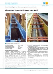
4.2 Functions<br />
The compact design and integrated functional components of the pipe puller permit the efficient pulling and joining of pipes of<br />
all kinds, e.g. concrete pipes, stoneware pipes etc. of a wide range of diameters.<br />
The pipe puller is composed of the following functional components:<br />
1. Undercarriage<br />
2. Hydraulic pulling cylinder with two grippers (at the front and rear) and a hydraulic opening cylinder<br />
3. Battery case<br />
4. Drive unit<br />
5. Socket clamp<br />
6. Extension tube, complete*<br />
7. Control panel complete with control cable and connection plug<br />
8. Rings<br />
9. Accessories<br />
The pipe carriage with its welded design carries all the above-mentioned functional components. It runs on angled hard<br />
rubber wheels. This angled arrangement enables the pipe puller to run smoothly inside pipes.<br />
Installed and locked in the centre of the pipe carriage is the pulling cylinder with a fitted gripping cylinder and the front and<br />
rear grippers. The max. stroke of the pulling cylinder, i.e. the pulling length of the pipe puller, is 500 mm per cycle. The<br />
battery case attached to the side accommodates the 12 V/160/180 Ah battery and has external + and - terminals that are<br />
connected via cables to the switch box on the opposite side. The drive unit is also situated on the opposite side.<br />
This unit consists of a hydraulic control block with solenoid valves and, installed immediately beneath, an electrohydraulic<br />
pump with a pressure indicator. After input of the relevant control commands at the control panel, this is <strong>use</strong>d <strong>for</strong> the pulling<br />
process and <strong>for</strong> opening and closing the grippers.<br />
The pulling element is an 18 mm diameter steel rope equipped with a load hook at one end and with the other end tapered<br />
and brazed.<br />
The steel pulling rope is fastened by means of the attached hook to the double sling. The double sling is hooked onto the rings<br />
on the ends of the selected pulling beam. The pulling beam is inserted in the pipe to be pulled by a labourer and held fast until<br />
the first pull. For the pulling process itself, the labourer must leave the trench.<br />
The other, tapered end of the steel pulling rope is passed over the opened cheeks of the front gripper, through the cylinder<br />
and over the cheeks of the opened rear gripper.<br />
The thrust bearing is the socket clamp which has to be positioned vertically with its support in the pipe socket with the aid of a<br />
spindle with a trapezoidal thread, possibly making <strong>use</strong> of an extension tube. We wish to explicitly point out that the socket<br />
clamp must only ever be <strong>use</strong>d with a single extension tube. The spindle is extended with hand grips until the pipe puller is<br />
firmly anchored in the socket.<br />
The hydraulic pulling cylinder is retracted when the appropriate buttons are pressed. The gripper automatically closes and the<br />
pipe is brought into position by the steel pulling rope.<br />
The operating procedure <strong>for</strong> the pulling process is described in detail in 7.1 and the following sections.<br />
11 Using instruction pipe puller<br />
Technical contents are subject to change. Publishing date 29/01/2010
4.3 Definition of intended purpose<br />
Caution! Compliance with the details of this section is absolutely essential. Using the pipe puller <strong>for</strong> any other<br />
purpose excludes claims under the manufacturer’s liability and warranty.<br />
The pipe puller may only be <strong>use</strong>d <strong>for</strong> its intended purpose (3/2-5). Any other <strong>use</strong> is impermissible and releases the<br />
manufacturer from any liability and warranty obligations.<br />
This manual must be available to the <strong>use</strong>r and to maintenance and servicing staff whenever the pipe puller is in <strong>use</strong>. Store a<br />
copy of this manual on the construction site close to the pipe puller. Keep a copy of this manual available during maintenance<br />
and servicing work.<br />
Check the technical condition of all bracing elements (socket clamp, pulling beam) be<strong>for</strong>e using the pipe puller.<br />
Damaged parts must not be <strong>use</strong>d. The pipe puller must not be operated with damaged parts.<br />
Use only the parts belonging to this pipe puller.<br />
Watch out <strong>for</strong> corrosion. Corroded machine components have properties differing from those of new components. Both<br />
function and safety may then be at risk.<br />
Be<strong>for</strong>e setting up the pipe puller, skilled operatives (5/1) must check the structural loads <strong>for</strong> the selected set-up with reference<br />
to all conditions and guidelines.<br />
4.4 Technical data of the pipe puller<br />
Suitable <strong>for</strong> pipe diameters 800 – 2,400 mm<br />
Steel pulling rope with hook<br />
Diameter 18 m<br />
Length 35 m (50 m, 60 m)<br />
Pulling cylinder stroke 500 mm<br />
Electrohydraulic gear pump 1.4 kW; 2,200 rpm; 12 V<br />
Working pressure Max. 160 bar<br />
Max. pulling <strong>for</strong>ce 107 kN<br />
Hydraulic fluid DEA ECONA E46<br />
biodegradable<br />
Hydraulic fluid quantity 15 L<br />
Power supply Battery; 12 V/160/180 Ah<br />
Total weight Approx. 456 kg<br />
Design Splash-proof<br />
Paint colours Yellow (RAL 1004)<br />
Red (RAL 2002)<br />
Green<br />
12 Using instruction pipe puller<br />
Technical contents are subject to change. Publishing date 29/01/2010
4.5 Electrical circuit diagram<br />
13 Using instruction pipe puller<br />
Technical contents are subject to change. Publishing date 29/01/2010
5. Safety instructions<br />
5.1 General in<strong>for</strong>mation<br />
The rules, instructions and safety provisions given in this section must be observed and complied with at all times.<br />
The pipe puller may only be operated by persons trained and instructed <strong>for</strong> this task.<br />
Lack of knowledge may result in damage to the pipe puller and put the operator at risk.<br />
The <strong>use</strong>r is defined as follows:<br />
i<br />
a) A skilled operative is someone who, thanks to his specialized training, knowledge, experience and familiarity with<br />
the relevant provisions, is capable of assessing the tasks the entrusted to him and identifying possible risks.<br />
b) An instructed person is someone who has been briefed on the tasks entrusted to him and the possible risks in the<br />
event of inappropriate action and possibly taught on the job and instructed on the necessary protective devices<br />
and protective measures.<br />
c) A layperson is someone who is neither a skilled operative as defined in a, nor an instructed person as defined in b.<br />
14 Using instruction pipe puller<br />
This applies particularly to maintenance and servicing and the inspection and remedying of malfunctions.<br />
Be<strong>for</strong>e using the pipe puller, operating and maintenance staff must be familiarized in detail with the unit and its parts. Be<strong>for</strong>e<br />
the machine is <strong>use</strong>d <strong>for</strong> the first time, staff must be in<strong>for</strong>med and instructed of danger areas in a safety training session. This<br />
safety training must be repeated as required.<br />
5.2 Special safety instructions<br />
When working on the pipe puller, i.e. during maintenance, adjustment and repair work, all drives capable of causing a<br />
potentially hazardous motion, must be disabled, e.g. motors, hoses, cylinders etc.).<br />
All operating and control elements as well as shut-off and control fittings of the pipe puller may only be operated by trained<br />
and authorized staff.<br />
i<br />
Obstacles, such as cables etc., must be eliminated or, if this is not possible, marked with suitable bicolour<br />
adhesive hazard warning tape.<br />
Injuries, even minor wounds, must be treated immediately to exclude the risk of infection.<br />
Traffic and escape routes must be kept free at all times.<br />
All accidents (personal injury or damage to property) must be reported immediately to the person in charge and<br />
the safety officer.<br />
The pipe puller is designed <strong>for</strong> compliance with the existing relevant rules and safety instructions <strong>for</strong> accident prevention<br />
assuming that it is <strong>use</strong>d <strong>for</strong> its intended purpose and operated correctly.<br />
i<br />
We must also point out that the pipe puller must only be <strong>use</strong>d <strong>for</strong> its intended purpose, with the exclusive<br />
<strong>use</strong> of original KRINGS parts. The manufacturer’s liability and warranty are excluded in the event of nonobservance.<br />
Technical contents are subject to change. Publishing date 29/01/2010
Note:<br />
- All the provisions of the statutory accident insurance institution <strong>for</strong> the German civil engineering industry (TBG)<br />
otherwise apply as well as<br />
- DIN 4124 “Excavations and trenches; slopes, breadths of working spaces, planking and strutting”.<br />
- Our products bear the TBG-GS “tested safety” mark.<br />
- Work on the hydraulics may only be per<strong>for</strong>med by skilled operatives (5.1). In cases of doubt, consult the<br />
15 Using instruction pipe puller<br />
ThyssenKrupp Ba<strong>use</strong>rvice After-Sales Service.<br />
- Do not carry out any work on the hydraulic system as long as the system is under pressure. Release the pressure<br />
from the hydraulic system be<strong>for</strong>e conducting maintenance and assembly work.<br />
- Do not release any screw joint on the KRINGS pipe puller while it is in operation or under load.<br />
- If the hydraulic fluid becomes excessively hot (characteristic smell), switch the KRINGS pipe puller off. Wait until<br />
the hydraulic fluid has cooled.<br />
- The service life of the hydraulic hoses is 3 years from delivery. Replace the hydraulic hoses at the end of this<br />
period. Failure to replace them puts staff and the pipe puller at risk.<br />
- Work on the electrics may only be per<strong>for</strong>med by skilled operatives (5.1). In cases of doubt, contact the<br />
ThyssenKrupp Ba<strong>use</strong>rvice After-Sales Service.<br />
- Be<strong>for</strong>e carrying out assembly or maintenance work on the electrics, disconnect the power supply by detaching the<br />
minus terminal from the battery.<br />
Technical contents are subject to change. Publishing date 29/01/2010
6. Operating and control elements and their purpose<br />
6.1 General in<strong>for</strong>mation<br />
Be<strong>for</strong>e using the machine <strong>for</strong> the first time, familiarize yourself with the function of the operating and control elements. This way<br />
you improve occupational safety and the quality of your work and at the same time reduce the risk of operating the pipe puller<br />
incorrectly, which may result in personal injury and damage to the machine. The purpose of these elements is explained in detail<br />
in the following.<br />
6.2 Functions of the control elements on the control panel<br />
No. Operating/control element Function<br />
1 White pushbutton OPEN Pressing the OPEN pushbutton opens the rear gripper and signal lamp 5<br />
indicates that the gripper is fully open.<br />
2 Black pushbutton CLOSE Pressing the CLOSE pushbutton closes the rear gripper and signal lamp 5<br />
indicates that the gripper is fully closed.<br />
3 White pushbutton EXT Pressing the EXT pushbutton extends the cylinder. When it reaches its limit<br />
position, the front gripper opens and signal lamp 5 indicates that the<br />
cylinder is fully extended.<br />
4 Black pushbutton PULL Pressing the PULL pushbutton retracts the cylinder. Its limit position is<br />
indicated again by signal lamp 5.<br />
5 Yellow signal lamp MAX. PRESS The functions of this signal lamp have already been explained above. It<br />
and multifunctional display also lights up when the set working pressure of 160 bar is reached.<br />
6 White signal lamp ON This signal lamp lights up when during the pulling process about 120 mm<br />
of stroke is left. This signal is issued by a limit switch that monitors cylinder<br />
travel.<br />
6.3 Control element <strong>for</strong> hydraulic pressure indication (manometer)<br />
The hydraulic pressure indicator is an instrument with a circular dial with two scales,<br />
in bar and psi. The measurement range extends from 0 to 250 bar and 0 to 35,000 psi.<br />
The electrohydraulic control unit has a factory-set pressure limit of 160 bar. When this<br />
pressure is reached, the signal lamp MAX. PRESS on the control panel lights up.<br />
This can be checked with the manometer <strong>for</strong> maintenance purposes (9.1 ff.) and to<br />
remedy malfunctions (8.1 ff.). During normal operation, the manometer is not visible<br />
as it is in the pipe together with the pipe puller.<br />
16 Using instruction pipe puller<br />
Technical contents are subject to change. Publishing date 29/01/2010
7. Initial operation, operation and supervision<br />
7.1 General in<strong>for</strong>mation<br />
On the assumption that you have read and understood the preceding sections of this manual, you can now <strong>use</strong> the pipe puller <strong>for</strong><br />
the first time.<br />
Daily routine checks<br />
- Check all the relevant operating and control elements <strong>for</strong> correct function.<br />
- Make sure be<strong>for</strong>e machine <strong>use</strong> that there is nothing that can prevent a smooth, trouble-free mechanical process.<br />
- Are the limit switches working properly?<br />
- Have the regreasable bearings been checked <strong>for</strong> a sufficient filling of grease? (See maintenance instructions in<br />
section 9.)<br />
- Has the battery been fully charged with the charger (not part of the supplied equipment)?<br />
- Is there sufficient fluid in the hydraulic system? (Check with fluid dipstick, see figure.)<br />
17 Using instruction pipe puller<br />
Technical contents are subject to change. Publishing date 29/01/2010
7.2 Initial operation<br />
Once all the above checks have been carried out and no problems have been found, proceed as follows:<br />
- The pipe puller is supplied in a prepared state. The battery has been charged and the hydraulic system is full of fluid.<br />
- No special measures have to be taken <strong>for</strong> initial operation.<br />
7.3 Operation<br />
- The pipe puller is supplied ready <strong>for</strong> operation. All that has to be<br />
done now is connect the power supply cable (1) to the power<br />
supply unit by inserting the plugs (2) in the polarized jacks (3)<br />
(see adjacent figure). Then insert the plug (4) of the control cable<br />
(5) in the socket (6) of the rope puller and secure. Connect the<br />
control cable to the control panel (see adjacent figure).<br />
- Carry out the routine daily checks (7.1).<br />
- Using suitable lifting gear (3.2), lift the fully operative pipe puller<br />
into the excavated trench. Move the pipe puller into a pipe that has<br />
already been laid.<br />
18 Using instruction pipe puller<br />
Technical contents are subject to change. Publishing date 29/01/2010
Clamp the pipe puller in the cleaned pipe with the socket clamp (4.3). Position the pipe puller parallel with the pipe<br />
axis and horizontally, with its support under the socket of the already laid pipe. Extend the spindle with the hand grips<br />
until the pipe puller is firmly anchored (4.3). Be<strong>for</strong>e the first pull, check that the pipe carriage really is firmly<br />
positioned. The socket clamp has to be tightened again after the first pull.<br />
Connect the steel pulling rope to the pulling beam via the double sling. Insert the pulling beam horizontally into the<br />
pipe. The steel pulling rope is thus held in this position at the same height as the pulling beam. The double sling must<br />
have ropes of equal length.<br />
Bring the control panel and control cable out of the danger zone of the pipe puller. The pipe puller must not be<br />
operated from within the pipe puller’s danger zone (7.5).<br />
- Open the rear gripper by pressing the ON pushbutton (1) on the control panel.<br />
- Extend the pulling cylinder by pressing the EXT pushbutton (3) on the control panel. When it reaches its limit position,<br />
the front gripper opens automatically.<br />
- Lay the steel pulling rope in both grippers.<br />
- Initiate the pulling process by pressing the PULL pushbutton (4) on the control panel. If the stroke of 500 mm is<br />
insufficient, the steel pulling rope has to be tensioned again. The pulling process has to be discontinued if the ON<br />
signal lamp (6) lights up.<br />
- Close the rear gripper by pressing the CLOSE pushbutton (2).<br />
- Extend the pulling cylinder by pressing the EXT pushbutton (3). The front gripper opens automatically as soon as it is<br />
free of load.<br />
- Initiate the pulling process by pressing the PULL pushbutton (4) on the control panel. After briefly pulling, open the<br />
rear gripper by pressing the OPEN pushbutton (1) on the control panel.<br />
- Release the pulling beam. Proceed in the same way <strong>for</strong> other pipes.<br />
19 Using instruction pipe puller<br />
Technical contents are subject to change. Publishing date 29/01/2010
7.4 Supervision<br />
i<br />
Make sure during the pulling process that no one is within the danger zone of the taut steel pulling rope and of<br />
possible entrapment risks in the area of the pulled pipe.<br />
Angled (non-horizontal) pulling ropes are not permitted.<br />
If the hydraulic fluid becomes excessively hot (characteristic smell), switch the KRINGS pipe puller off. Wait until the<br />
hydraulic fluid has cooled.<br />
If the pulling process is interrupted without the MAX. PRESS signal lamp (5) lighting up, check the battery’s charge<br />
level. Replace or recharge battery (6.2, 9.2).<br />
8 Malfunctions, ca<strong>use</strong>s and remedies<br />
8.1 General in<strong>for</strong>mation<br />
This section describes malfunctions that can occur during the work process with their possible ca<strong>use</strong>s and remedies.<br />
i<br />
Malfunctions of the electrical systems and those affecting the mechanics and hydraulics that are not covered below<br />
may only be remedied by skilled staff. The general rules <strong>for</strong> the elimination of malfunctions in accordance with<br />
accident prevention regulations must always be observed.<br />
During the work process, the following malfunctions can occur on the properly maintained pipe puller.<br />
- The pipe puller doesn’t pull.<br />
- The pipe puller runs out of the pipe.<br />
8.2 Malfunctions<br />
1. The pipe puller doesn’t pull.<br />
Ca<strong>use</strong> Consequence Remedy<br />
Battery not charged The MAX. PRESS signal lamp Recharge the battery or replace it<br />
fails to light up. with a charged battery.<br />
Obstacle in the pipe puller’s path The MAX. PRESS signal lamp lights up. Remove the obstacle.<br />
The gripper cheeks don’t grip. The hydraulic pulling cylinder retracts Replace the cheeks and check the<br />
without pulling the steel pulling rope. springs as described in 9.4. Tighten<br />
screw on rear gripper if necessary.<br />
Steel pulling rope broken Steel rope sags during pulling process. Replace steel rope.<br />
Motor of the hydraulic. The pipe puller doesn’t pull The MAX.. Have the motor checked by one of<br />
unit doesn’t work PRESS signal lamp on the control panel our fitters or specialist staff.<br />
fails to light up. The battery is charged<br />
and all the electrical cables are connected.<br />
2. The pipe puller runs out of the pipe.<br />
The socket clamp isn’t firmly The pipe puller runs out of the pipe during Check and reposition the pipe puller in<br />
clamped in the pipe. the pulling process. the pipe with the socket clamp. Adjust<br />
with the appropriate extension tube.<br />
Retighten after the first pull (4.3).<br />
20 Using instruction pipe puller<br />
Technical contents are subject to change. Publishing date 29/01/2010
9 Maintenance and servicing<br />
9.1 General in<strong>for</strong>mation<br />
Meticulous maintenance of the pipe puller keeps it in good working order and extends the service life of important parts and<br />
components.<br />
This section describes the tasks and checks that are to be carried out by trained operating staff at the intervals given.<br />
i<br />
The maintenance and servicing tasks must be carried out in observance of the provisions of the law and ordinances,<br />
e.g. accident prevention rules, Workplace Ordinance, Hazardous Substances Ordinance etc. They must be carried<br />
solely by skilled and trained staff or by the ThyssenKrupp Ba<strong>use</strong>rvice Sales Service..<br />
Cleanliness keeps the <strong>Krings</strong> pipe puller in good working order. Regularly remove excessive dirt. Only then can you<br />
spot in good time wear and any repairs that may be necessary be<strong>for</strong>e expensive consequential damage occurs.<br />
To ensure optimum and trouble-free operation of the pipe puller, the following tasks should be regularly per<strong>for</strong>med at the given<br />
intervals.<br />
Note<br />
The intervals differ from <strong>use</strong>r to <strong>use</strong>r, i.e. they depend, <strong>for</strong> example, on the frequency of equipment <strong>use</strong> and<br />
on the number of shifts worked (single or multiple shifts).<br />
21 Using instruction pipe puller<br />
In this connection we refer to DIN 31051, Part 1, “Maintenance, concepts and measures”.<br />
Caution<br />
Only the original or equivalent parts approved by the manufacturer are to be <strong>use</strong>d as replacement or spare<br />
parts. Liability and warranty claims are excluded in the event of non-observance of this point (see 2.1 and<br />
2.2).<br />
Technical contents are subject to change. Publishing date 29/01/2010
9.2 Overview of maintenance<br />
Maintenance tasks<br />
Battery X<br />
Electrical contacts, check plug<br />
connections<br />
Electrical supply lines X<br />
Control cable with plug, control panel X<br />
Hydraulic hoses X<br />
Pipe pulling cylinder X<br />
Hydraulic pump housing X<br />
Check gripper cheeks X<br />
Check springs X<br />
Check steel pulling rope X<br />
Check wheels X<br />
Grease wheel axles X<br />
Replace hand grips X<br />
22 Using instruction pipe puller<br />
Intervals<br />
As required Daily,<br />
every 8<br />
h<br />
Visual and functional check X<br />
Electrical power supply X<br />
Check hydraulics X<br />
Clean machine X<br />
X<br />
Monthly,<br />
every<br />
160 h<br />
Hydraulic pump housing damp? X<br />
Grease socket clamp spindle X<br />
Grease gripper axles X<br />
Grease battery terminals X<br />
Annually,<br />
every<br />
2,000 h<br />
Change hydraulic fluid X<br />
Clean fluid filter X<br />
Technical contents are subject to change. Publishing date 29/01/2010
9.3 Maintenance as required<br />
Re-apply the anti-corrosion coating on the <strong>Krings</strong> pipe puller as required. Make sure that no elastic seals or bearings come into<br />
contact with paints and thinners.<br />
.<br />
- Observe the maintenance instructions <strong>for</strong> the battery.<br />
These are on the top of the battery in the power supply unit.<br />
- Check the electrical contacts/plug connections. When inserting<br />
the plugs (2) of the power supply cable (1) into the<br />
polarized jacks (3) on the battery case, check the plugs and jacks<br />
<strong>for</strong> damage, a tight fit and corrosion. Replace the<br />
plugs or jacks as required.<br />
- Check the electrical supply lines <strong>for</strong> damage to the insulation,<br />
kinking or crushing and replace if necessary.<br />
- Check the hydraulic hoses <strong>for</strong> leaks, damage to the outer sheathing, kinking or crushing. In the event of damage,<br />
these must be replaced by specialist staff. The screw joints can be tightened with suitable tools if necessary.<br />
23 Using instruction pipe puller<br />
Technical contents are subject to change. Publishing date 29/01/2010
- Check the pipe pulling cylinder (1) and opening cylinder (2) <strong>for</strong> leaking fluid. In the event of fluid leaks on the pipe<br />
pulling or opening cylinders, the pipe puller must be switched off and a repair carried out by one of our fitters or a<br />
skilled operative.<br />
- The hydraulic pump housing (3) must be checked <strong>for</strong> mechanical damage and tightness. The thread of the lid on the<br />
front must be checked <strong>for</strong> completeness and tightness. Any defects must be eliminated. The lid seal must be checked<br />
<strong>for</strong> tightness and damage and replaced if necessary.<br />
- Check the cheeks (4) of the grippers <strong>for</strong> wear. If the cheeks are strongly worn, the steel rope may slip. Should the<br />
cheeks of either of the grippers be strongly worn, replace them. Remove the plugs of the power supply cable from<br />
their jacks (9.2). Remove the split pins (7) and those of the springs (8). Drive the gripper axles out of their holes with a<br />
pointed tool. Replace the worn cheeks with new original <strong>Krings</strong> replacement parts. To reassemble, adopt the above<br />
procedure but in reverse order. Grease the axles with roller bearing grease be<strong>for</strong>ehand.<br />
- Check the springs (8) of the grippers (5) <strong>for</strong> correct function. Replace if necessary.<br />
- Check the steel pulling rope (6) <strong>for</strong> wear. Replace if it is strongly worn or mechanically damaged. Bear in mind the<br />
danger of a snapping rope.<br />
- Check the wheels (9) <strong>for</strong> smooth running and damage. If they do not run smoothly or are mechanically damaged,<br />
they must be replaced with original replacement parts. Grease the bearings as required with roller bearing grease.<br />
- Check the wheel axles <strong>for</strong> mechanical damage. Any damage must be eliminated by skilled staff or one of our fitters.<br />
- Check the plastic-covered grips of the spindle <strong>for</strong> damage. Replace the plastic grips as required with original<br />
replacement parts.<br />
- Take appropriate measures to protect the machine as a whole from corrosion.<br />
24 Using instruction pipe puller<br />
Technical contents are subject to change. Publishing date 29/01/2010
9.4 Daily maintenance<br />
i<br />
1. Visual and functional check of all operating and control elements<br />
25 Using instruction pipe puller<br />
- Signal lamps. Pressing the EXT pushbutton (3) on the control panel extends the pulling cylinder. When it reaches<br />
its limit position, the front gripper opens and the MAX. PRESS signal lamp (5) lights up yellow. By pressing the<br />
PULL pushbutton (4) on the control panel, the pulling cylinder retracts. When only about 120 mm of stroke is left<br />
during the pulling process, the ON signal lamp (6) lights up white. Should any of the signal lamps fail to light up,<br />
the bulb must be replaced. To this end, carefully unscrew the coloured cap over the signal lamp to af<strong>for</strong>d access<br />
o the faulty bulb. Check the bulb and replace if necessary. Then check again <strong>for</strong> correct function.<br />
- Pushbuttons. The EXT and PULL pushbuttons have already undergone a functional check. Pressing the OPEN<br />
pushbutton (1) on the control panel ca<strong>use</strong>s the rear gripper to open. Pressing the CLOSE pushbutton (2) on the<br />
control panel ca<strong>use</strong>s the rear gripper to close again.<br />
If any of the above functions fails to be per<strong>for</strong>med, the control panel must be inspected by one of our fitters or a<br />
skilled operative and repaired if necessary.<br />
- Limit switch on the rope pulling cylinder. When only about 120<br />
mm of stroke is left, the ON signal lamp must light<br />
up. If the bulb is faulty, it must be replaced. If the signal lamp<br />
still fails to light up, the limit switch on the rope pulling cylinder<br />
(see adjacent figure) must be inspected by one of our fitters or<br />
a skilled operative and repaired if necessary.<br />
2. Electrical power supply.<br />
Charge the battery with a suitable charger*.<br />
(Charger not included in the equipment supplied.)<br />
3. Hydraulics Check the hydraulic fluid level with the dipstick,<br />
with the pulling cylinder in its retracted state.<br />
Cleanliness here is essential. Clean the entire top of the,<br />
hydraulic fluid tank be<strong>for</strong>ehand. If sufficient fluid is in the<br />
tank, the level is between the two markings (see adjacent figure).<br />
Check the dipstick be<strong>for</strong>e <strong>use</strong> <strong>for</strong> any dirt sticking to it and wipe<br />
clean with a soft cloth. Top up with DEA ECONA E46 if necessary<br />
by pouring fluid into the hole otherwise occupied by the dipstick.<br />
Technical contents are subject to change. Publishing date 29/01/2010
Protect the pipe puller from penetrating water and flooding. Do not leave the pipe puller unattended in<br />
trenches (e.g. overnight or at weekends).<br />
26 Using instruction pipe puller<br />
Please bear in mind that the pipe puller is splash-proof only (4.4).<br />
In the event of flooding, we advise the following procedure:<br />
1. Recover the pipe puller from the trench.<br />
2. Do not put the pipe puller back into service!<br />
3. Send the pipe puller to the manufacturer’s plant <strong>for</strong> inspection and repair.<br />
Condition of the hydraulic fluid<br />
The ageing of the hydraulic fluid depends on the pipe puller’s operating conditions. Ageing and serviceability can be assessed<br />
with a simple visual inspection.<br />
Darkening<br />
Overheating, failure to change the fluid in time or mixing with a different fluid.<br />
Cloudiness<br />
Penetration of water or air<br />
Air bubbles<br />
Penetration of air, e.g. as a consequence of too little fluid or a leaky intake line.<br />
Suspended or deposited impurities<br />
Abrasion, dirt, products of ageing<br />
Smell of burnt oil<br />
Overheating<br />
All of these phenomena are signs of diminished quality. These defects and their ca<strong>use</strong>s must be remedied be<strong>for</strong>e resuming<br />
operation of the pipe puller.<br />
9.5 Monthly maintenance<br />
- Check the hydraulic pump housing <strong>for</strong> condensation.<br />
To this end, remove the drainage screw (see adjacent figure,<br />
arrow). Allow any condensation to completely drain out.<br />
Then screw the drainage screw back on.<br />
- Grease the socket clamp spindle via the lubricating nipple<br />
with the aid of a grease gun containing graphite grease.<br />
Remove any excess grease.<br />
- Grease the gripper axles. To this end, release the axles as<br />
above (9.4). Coat the axles with roller bearing grease.<br />
Then refit the axles with the method shown in 9.4 (see figure below).<br />
- Coat the battery terminals with terminal grease.<br />
Technical contents are subject to change. Publishing date 29/01/2010
9.6 Annual maintenance<br />
- Change the hydraulic fluid. Remove the magnetic fluid drainage screw (see figure on preceding page, arrow). Allow<br />
the old hydraulic fluid to drain out. Collect the old fluid and dispose of it in accordance with the applicable laws and<br />
regulations. Inspect the magnetic drainage screw <strong>for</strong> metal abrasion. In the event of such abrasion, the pipe puller<br />
must be inspected <strong>for</strong> possible damage by one of our fitters. After screwing the fluid drainage screw back on, fill the<br />
tank with new DEA ECONA E46 hydraulic fluid until the level on the dipstick is between the two markings.<br />
- Clean or replace the fluid filter. When replacing the hydraulic fluid, the filter in the fluid tank must be replaced with a<br />
new one. To this end, release the screws on the lid of the fluid tank. Then lift the lid seal so that the filter at the mouth<br />
of the intake pipe can be removed. After replacement, close the tank according to the above procedure, but in reverse<br />
order.<br />
- According to Art. 10 of the Workplace Ordinance, recurrent inspection of the pipe puller is obligatory.<br />
10 Appendix<br />
10.1 Declaration relating to the manual<br />
Supplement to the manual by ThyssenKrupp Ba<strong>use</strong>rvice <strong>GmbH</strong> as a result of legal provisions.<br />
This manual is based on that issued by Rücker <strong>GmbH</strong> on behalf of <strong>Krings</strong> Maschinenbau <strong>GmbH</strong>.<br />
The current edition is based on edition 07.94 and the changes agreed with <strong>Krings</strong> Maschinenbau <strong>GmbH</strong> on 20.12.94.<br />
We declare as follows:<br />
This manual is part of the documentation under the terms of the EC Machinery Directive. It is a precondition <strong>for</strong> the Declaration of<br />
Con<strong>for</strong>mity <strong>for</strong> obtaining the CE mark.<br />
This manual complies with the following laws and guidelines:<br />
EC Machinery Directive, Appendix 5.6<br />
EN 292 T1, section 5.6 and T2, section 5<br />
Product Liability Act of 01.01.90, compliance with the Product Liability Directive, reference to “instruction obligation”<br />
The Equipment Act (GSG 3, paragraph 3); partially covered by the Machinery Directive since 01.01.93<br />
DIN V 8418; partially covered by the Machinery Directive<br />
Art. 823 BGB (German Civil Code), fault-related liability relating to machine operation and ensuring traffic safety<br />
TBG (accident insurance institution <strong>for</strong> the civil engineering industry) guideline<br />
Accident prevention regulations<br />
The technical and factual correctness of the manual together with the above-mentioned changes was ascertained on 20.12.94.<br />
We wish to explicitly note that the manual must not be amended without our knowledge. Warranty claims are excluded in the<br />
event of unauthorized changes.<br />
The warnings and pictograms to which the manual refers are attached by the manufacturer.<br />
Manufacturer: KRINGS VERBAU GMBH, Am Weidenhof 8, 52525 Heinsberg, Germany<br />
27 Using instruction pipe puller<br />
Technical contents are subject to change. Publishing date 29/01/2010
Mention d‘impression<br />
Éditeur<br />
ThyssenKrupp Ba<strong>use</strong>rvice <strong>GmbH</strong><br />
Geschäftsbereich <strong>Emunds</strong>+<strong>Staudinger</strong> / <strong>Krings</strong><br />
Ottostraße 30<br />
41836 Hückelhoven / Baal<br />
Germany<br />
Tel.: +49 2433 453-0<br />
Fax: +49 2433 453-100<br />
Email: ES-<strong>Krings</strong>@thyssenkrupp.com<br />
www.es-verbau.com<br />
Dessin, Production<br />
visaplan <strong>GmbH</strong>, Bochum<br />
www.visaplan.com<br />
.<br />
28 Using instruction pipe puller<br />
Technical contents are subject to change. Publishing date 29/01/2010