Motorola DVR Self Install Guide - Comcast
Motorola DVR Self Install Guide - Comcast
Motorola DVR Self Install Guide - Comcast

You also want an ePaper? Increase the reach of your titles
YUMPU automatically turns print PDFs into web optimized ePapers that Google loves.
For use with the <strong>Motorola</strong> <strong>DVR</strong> box.<br />
For more information call<br />
1-888-COMCAST or go to www.comcast.com/dvr.<br />
FOR THOSE WHO<br />
CAN’T WAIT TO<br />
USE THEIR <strong>DVR</strong><br />
DIGITAL VIDEO RECORDER<br />
SELF-INSTALL GUIDE
YOU JUST COULDN’T WAIT, COULD YOU? YOU RUSHED STRAIGHT HOME, TORE<br />
OPEN THE BOX, AND NOW YOU’RE SITTING IN FRONT OF YOUR TV, <strong>DVR</strong> IN HAND,<br />
JUST ITCHING TO HOOK IT UP. HEY, WE UNDERSTAND. WITH <strong>DVR</strong>, YOU GET TV ON<br />
YOUR TERMS. SO SHOULDN’T THE INSTALLATION BE ON YOUR TERMS, TOO? YEAH,<br />
WE THOUGHT SO. NOW SIT BACK AND RELAX. THIS ISN’T GOING TO HURT A BIT.<br />
INSTALL YOUR <strong>DVR</strong><br />
IN A FEW EASY STEPS<br />
TALK ABOUT EASY. YOUR NEW <strong>DVR</strong> SET-TOP BOX BASICALLY TAKES THE PLACE OF YOUR<br />
CURRENT SET-TOP BOX. SO IN ESSENCE, YOU’RE REPLACING THE OLD BOX WITH THE NEW<br />
ONE. BELOW ARE SOME HELPFUL HINTS, PLUS DETAILED INSTRUCTIONS ON HOW TO<br />
CONNECT YOUR NEW <strong>DVR</strong> TO A VCR AND/OR HOME THEATER SYSTEM.<br />
! IMPORTANT SAFETY INSTRUCTIONS<br />
YOUR <strong>DVR</strong> BOX IS A MOTOROLA DCT6412 — AN ADVANCED INTERACTIVE DIGITAL CABLE RECEIVER.<br />
THE <strong>DVR</strong> SET-TOP BOX HAS AN INTERNAL HARD DISK DRIVE. TO HELP REDUCE THE POTENTIAL FOR<br />
DAMAGE, IT MUST BE HANDLED IN MUCH THE SAME WAY AS A COMPUTER. THE <strong>DVR</strong> HAS BEEN<br />
DESIGNED TO OPERATE RELIABLY IN A WELL-VENTILATED HOUSEHOLD ENVIRONMENT.<br />
• Position the <strong>DVR</strong> in an open space that allows airflow around the unit (there should be at<br />
least 2 inches of space above and on all sides).<br />
• Slots and openings in the unit cabinet are provided for ventilation. Do not block the slots and<br />
openings in the <strong>DVR</strong> or place anything on top of the <strong>DVR</strong>. Also, you should place the <strong>DVR</strong> on<br />
a hard surface with adequate support.<br />
• Ensure the <strong>DVR</strong> is not near any external heat source that could raise the temperature<br />
around the unit.<br />
• To prevent fire or shock hazard, do not expose this appliance to rain or moisture. Unplug the<br />
unit from the wall outlet before cleaning. Do not use liquid cleaners or aerosol cleaners. Use<br />
a damp cloth for cleaning. <strong>Comcast</strong> recommends that you use a surge protector to power your<br />
digital converter box.<br />
> INSTALLATION OVERVIEW<br />
Your <strong>DVR</strong> box can support a variety of video and audio formats, including standard-definition<br />
and high-definition TV, and analog and digital audio. With this versatility, your <strong>DVR</strong> box can be<br />
connected to a basic TV and VCR or it can be easily incorporated into a high-end home<br />
entertainment center.<br />
To connect your equipment, you will need to understand what ports your electronic equipment<br />
(e.g. TV, VCR, A/V receiver) has, then determine what cables you want to use to connect these<br />
devices. There are many options for cables at varying levels of quality. Once you determine the<br />
connections your equipment supports, you will be able to make your choice of cables. Refer to<br />
the following two pages for more detailed information on video and audio connections. If your<br />
equipment is already connected, then it’s easy — all you have to do is replace your current<br />
cable set-top box with your new <strong>DVR</strong>.
VIDEO AND AUDIO CONNECTIONS<br />
Video Connections<br />
Your <strong>DVR</strong> can output both standard-definition and high-definition programming. The video<br />
connections you use depend on what type of TV you have and the connectors available.<br />
Video connections to standard-definition TV<br />
Most TVs in use today are standard definition. If you are connecting your <strong>DVR</strong><br />
to a standard-definition TV, you will use one of the following connections:<br />
• RF coaxial cable: This connection does not support Dolby Digital 5.1. If your TV set only<br />
has an RF input, a separate RF modulator is required to connect the <strong>DVR</strong> to your TV set.<br />
• Composite video: Use a single RCA cable (typically color-coded yellow).<br />
• S-video: Use single S-video cable.<br />
Using the composite or S-video connections will provide better picture quality than<br />
the RF coaxial connection, if your equipment supports these connections.<br />
Video connections to high-definition TV<br />
To connect your <strong>DVR</strong> to an HDTV, use one of the following connections:<br />
• Component Video (Y Pb Pr): Use 3 component video cables<br />
(typically color-coded green, blue, and red).<br />
• DVI: Digital Video Interface (typically available only on newer HDTVs).<br />
You must use either component video connections or a DVI connection for HDTV — the<br />
video connections used for standard-definition programming do not support HDTV.<br />
Audio Connections<br />
To connect your <strong>DVR</strong> to your TV or your audio/video receiver, you will use one of the following:<br />
• Stereo audio: Use RCA cables (often a joined pair with one red and one white).<br />
• Digital coaxial audio: Use digital coaxial cable (typically color-coded orange).<br />
• Optical digital audio: Use fiber-optic cable.<br />
Note: Digital audio connections (digital coaxial or optical) are required to pass Dolby Digital 5.1<br />
or 7.1 signals to your components.<br />
The most common connection in use today is stereo audio. The audio connection options<br />
above can be used for a standard-definition or high-definition TV. If your equipment supports it,<br />
the optical (OPTICAL SPIDF) or coaxial (SPIDF) audio outputs on the <strong>DVR</strong> may be used in place<br />
of the stereo audio outputs (AUDIO R and L) and generally offer a higher level of audio quality.<br />
TIP: Composite video and stereo audio cables often come as three joined RCA<br />
cables (yellow is used for video connections, red and white for right and left<br />
audio connections).<br />
DVI<br />
COMPONENT<br />
VIDEO<br />
S-VIDEO<br />
COMPOSITE<br />
VIDEO<br />
RF COAXIAL<br />
CABLE<br />
OPTICAL<br />
DIGITAL AUDIO<br />
DIGITAL<br />
COAXIAL AUDIO<br />
STEREO<br />
AUDIO<br />
VIDEO / AUDIO CONNECTOR GUIDE<br />
VIDEO CONNECTORS<br />
Digital Video Interface. All digital, high-quality video<br />
connection. DVI connection is typically available only<br />
on new equipment. Supports high-definition video.<br />
High-quality video connection that uses 3 separate<br />
component video cables. The cables are generally<br />
color-coded green, blue, and red. Supports<br />
high-definition video.<br />
S-video connection provides a high-quality,<br />
standard-definition picture. Offers higher-quality<br />
picture than composite video or RF coaxial cables.<br />
Common connection for standard TVs or VCRs. It typically<br />
has a yellow connector that supports a single RCA cable.<br />
Common cable connection. Carries both video and audio<br />
signals over a single cable. If your TV set only has an RF<br />
input, a separate RF modulator is required to connect the<br />
<strong>DVR</strong> to your TV set.<br />
AUDIO CONNECTORS<br />
High-quality audio connection that uses fiber-optic cable.<br />
Requires one cable. Connector on electronic device may<br />
include “Toslink” or “SPIDF” in the label.<br />
High-quality coaxial cable with RCA-type connector<br />
(typically color-coded orange) that transfers sound<br />
digitally. Requires one cable. Connector on electronic<br />
device may include “SPIDF” in the label.<br />
RCA cables that often have a joined pair of RCA cables<br />
with one red and one white. These cables are used to<br />
connect a stereo to other equipment such as a VCR or<br />
DVD player.
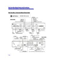
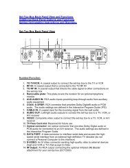
THE <strong>DVR</strong> BACK PANEL<br />
1 2 3 4<br />
5 6 7<br />
8 9<br />
1 CABLE IN The CABLE IN port receives the incoming signal from <strong>Comcast</strong>.<br />
2 AUDIO IN R These ports are used to connect a set-top box between a peripheral audio<br />
AUDIO IN L device such as a CD player and a stereo tuner or A/V receiver. The audio<br />
from the peripheral device will pass through the <strong>DVR</strong> when it is turned off.<br />
3 SPDIF The orange coaxial SPDIF port is a digital output connection that carries Dolby<br />
Digital 5.1 audio or PCM audio. It is used to connect the <strong>DVR</strong> to a stereo tuner or<br />
A/V receiver to provide surround-sound, theater-style audio.<br />
4 VIDEO IN The VIDEO IN port accepts a composite video input from a VCR, camcorder<br />
VIDEO OUT or other video device (not currently enabled). The VIDEO OUT port is used to<br />
deliver composite video to an external device such as a VCR or TV.<br />
5 DVI-D The Digital Video Interface is used to connect a high-definition monitor or a<br />
high-definition television.<br />
6 AUDIO OUT R The RCA audio ports are used to deliver audio to a stereo receiver.<br />
AUDIO OUT L<br />
7 Y Pb Pr These ports are used to deliver component video to an HD-ready TV or monitor.<br />
Though capable of delivering standard-definition video to your TV or monitor, these<br />
cables are necessary to deliver high-definition video.<br />
8 S-VIDEO This port is used to deliver high-quality, standard-definition video to external<br />
devices that accept S-video inputs, such as a high-end VCR or TV.<br />
9 OPTICAL SPDIF The OPTICAL SPDIF port is an optical digital output connection that carries Dolby<br />
Digital 5.1 audio or PCM audio. It is used to connect the <strong>DVR</strong> to a stereo tuner or<br />
A/V receiver to provide surround-sound, theater-style audio.<br />
START YOUR <strong>DVR</strong><br />
INSTALLATION HERE<br />
0.0 PREPARE FOR INSTALLATION<br />
1. Ensure all electronic devices involved in the installation are unplugged. Do not plug the<br />
<strong>DVR</strong> power cord into a wall outlet until you have completed all connections between<br />
the <strong>DVR</strong> and other devices.<br />
2. Place the <strong>DVR</strong> in the desired location. Be sure the <strong>DVR</strong> is where you want it before<br />
connecting it to other devices. Ensure your cables are of sufficient length to reach the<br />
required components.<br />
TIP: Labels used for ports on electronic equipment vary, but generally contain IN or OUT.<br />
When connecting 2 devices, the OUT port of one device should always be connected<br />
to the IN port of the other device.<br />
0.1 CHOOSE YOUR INSTALLATION SETUP<br />
There are multiple ways to connect your electronic equipment. Below are some common<br />
configurations. Please choose the one that best fits your setup and proceed to the<br />
appropriate section on the following pages.<br />
> CONNECTING YOUR <strong>DVR</strong> TO A STANDARD-DEFINITION TV<br />
1.0 STEREO TV AND STEREO VCR INSTALLATION<br />
2.0 STANDARD TV AND VCR INSTALLATION<br />
3.0 TV WITH S-VIDEO INSTALLATION<br />
4.0 STEREO TV AND A/V RECEIVER INSTALLATION<br />
> CONNECTING YOUR <strong>DVR</strong> TO A HIGH-DEFINITION TV<br />
5.0 HDTV AND STEREO VCR INSTALLATION<br />
6.0 HDTV AND A/V RECEIVER INSTALLATION<br />
Note: All connections to both the TV and the VCR allow you to record the program being shown on the<br />
TV using the VCR, be it a “live” program or something previously recorded on the <strong>DVR</strong>. With a VCR<br />
recording, any banners or messages shown on the TV will also be recorded on the VHS tape.
1.0 STEREO TV AND STEREO VCR INSTALLATION<br />
For stereo sound, use RCA cables to connect the <strong>DVR</strong> to the TV and/or the VCR. Three connections<br />
must be made between each device: VIDEO, AUDIO RIGHT, and AUDIO LEFT. To make these<br />
connections easier, the ends of the RCA cables are usually color-coded. Yellow is used for VIDEO,<br />
red for AUDIO RIGHT, and white for AUDIO LEFT.<br />
Cable/<br />
Antenna IN<br />
Cable/<br />
Antenna OUT<br />
Cable/<br />
Antenna IN<br />
CABLE<br />
IN<br />
Audio IN<br />
R L<br />
Audio OUT<br />
R L<br />
1. Connect an RCA video cable (yellow) to the VIDEO OUT (yellow) jack on the <strong>DVR</strong> and to the<br />
VIDEO IN port on the VCR.<br />
2. Connect RCA audio cables (one red and one white) to the AUDIO OUT R (red) and AUDIO OUT L<br />
(white) jacks on the <strong>DVR</strong> and to the AUDIO RIGHT and AUDIO LEFT inputs on the VCR.<br />
3. Connect an RCA video cable (yellow) to the VIDEO OUT port on the VCR and the VIDEO INPUT<br />
port on the TV.<br />
4. Connect RCA audio cables (one red and one white) to the AUDIO RIGHT and AUDIO LEFT<br />
outputs on the VCR and the AUDIO RIGHT and AUDIO LEFT inputs on the TV.<br />
If you do not have a VCR and want to connect your <strong>DVR</strong> to a stereo TV, complete<br />
these steps:<br />
1. Connect a video RCA cable (yellow) to the VIDEO OUT jack on the <strong>DVR</strong> and the VIDEO INPUT<br />
port on the TV.<br />
2. Connect audio RCA cables (one red and one white) to the AUDIO OUT R (red) and AUDIO OUT<br />
L (white) jacks on the <strong>DVR</strong> and to the AUDIO RIGHT and AUDIO LEFT inputs on the TV.<br />
PROCEED TO SECTION 7.0, FINAL CONNECTIONS.<br />
IR<br />
INPUT 1<br />
R<br />
L<br />
USB<br />
Video IN<br />
Video OUT<br />
INPUT 2<br />
R<br />
L<br />
DVI-D OUT<br />
S-Video<br />
Video<br />
Audio<br />
AUDIO IN<br />
VIDEO<br />
R L SPDIF IN OUT<br />
R L<br />
AUDIO<br />
OUT<br />
VCR<br />
TV<br />
Y Pb Pr<br />
TV<br />
Pass Card<br />
S-VIDEO<br />
OPTICAL<br />
SPDIF<br />
IEEE 1394<br />
SWITCHED<br />
105/125V<br />
60Hz<br />
4A MAX<br />
500W MAX<br />
CONVENIENCE<br />
OUTLET<br />
<strong>DVR</strong><br />
2.0 STANDARD TV AND VCR INSTALLATION<br />
The connection from the <strong>DVR</strong> to the TV and the VCR uses standard RF coaxial cables. If you are<br />
choosing this setup, a separate RF modulator is required.<br />
Note: Audio through the coaxial output port is mono. For stereo sound, RCA connector cables<br />
must be used as described in Section 1.0.<br />
<strong>DVR</strong><br />
DVI-D OUT<br />
RF Modulator<br />
RF OUT<br />
RF OUT<br />
RF IN<br />
VCR<br />
TV<br />
RF IN<br />
1. Connect an RCA video cable (yellow) to the VIDEO OUT (yellow) jack on the <strong>DVR</strong> and to the<br />
VIDEO IN port on the RF modulator.<br />
2. Connect RCA audio cables (one red and one white) to the AUDIO OUT R (red) and AUDIO<br />
OUT L (white) jacks on the <strong>DVR</strong> and to the AUDIO RIGHT and AUDIO LEFT inputs on the<br />
RF modulator.<br />
3. Connect the coaxial cable to the RF OUT port on the RF modulator and the RF IN port on<br />
the VCR.<br />
4. Connect the coaxial cable to the RF OUT port on the VCR and the RF IN port on the back<br />
of the TV.<br />
5. Make sure that the TV and the VCR are set to either channel 3 or channel 4, depending<br />
on the settings of the RF modulator. The TV, VCR and RF modulator should all be set to the<br />
same channel.<br />
If you do not have a VCR and want to connect your <strong>DVR</strong> directly to your TV, complete<br />
these steps:<br />
1. Connect a video RCA cable (yellow) to the VIDEO OUT jack on the <strong>DVR</strong> and the VIDEO INPUT<br />
port on the separate RF modulator.<br />
2. Connect audio RCA cables (one red and one white) to the AUDIO OUT R (red) and AUDIO<br />
OUT L (white) jacks on the <strong>DVR</strong> and to the AUDIO RIGHT and AUDIO LEFT inputs on the TV.<br />
(Continued on next page)
3. Connect a coaxial cable to the RF OUT port on the RF modulator and to the RF IN port on<br />
the TV.<br />
4. Make sure that the TV is set to either channel 3 or channel 4 depending on the setting of<br />
the RF modulator. Both the TV and the RF Modulator should be set to the same channel.<br />
Note: In some areas <strong>Comcast</strong> offers a single tuner <strong>Motorola</strong> DCT6208 <strong>DVR</strong>. This-set top box has<br />
an RF output and does not require a separate RF modulator.<br />
PROCEED TO SECTION 7.0, FINAL CONNECTIONS.<br />
3.0 TV WITH S-VIDEO INSTALLATION<br />
Some televisions have an alternate video connection called S-video that provides a higher quality<br />
picture than composite video or RF coaxial cable connections. If your equipment has S-video<br />
connections and you want the highest quality picture for your standard TV, use an S-video cable.<br />
You will use RCA cables (one red and one white) for audio when using an S-video connection.<br />
DVI-D OUT<br />
Three connections must be made between the <strong>DVR</strong> and the TV. They are S-VIDEO, AUDIO RIGHT,<br />
and AUDIO LEFT. You will use an S-video cable and RCA audio cables. To make these connections<br />
easier, the ends of the RCA cables are usually color-coded. Red is used for AUDIO RIGHT and<br />
white is used for AUDIO LEFT.<br />
1. Connect an S-video cable to the S-VIDEO jack on the <strong>DVR</strong>. Connect the other end to the<br />
S-VIDEO INPUT on the back of the TV.<br />
2. Connect the RCA audio cables (one red and one white) to the AUDIO OUT R (red) and AUDIO<br />
OUT L (white) jacks on the <strong>DVR</strong> and to the AUDIO RIGHT and AUDIO LEFT inputs on the TV.<br />
Note: If you have RCA cables that also have a video cable (yellow connector) but are using<br />
S-video connections, do not plug the yellow connector on the RCA cable into either<br />
the <strong>DVR</strong> box or the TV — the yellow cable is not used in this installation scenario.<br />
PROCEED TO SECTION 7.0, FINAL CONNECTIONS.<br />
TV<br />
<strong>DVR</strong><br />
4.0 STEREO TV AND A/V RECEIVER INSTALLATION<br />
Think of the A/V receiver of a home theater system as a switching device. Everything should be<br />
connected to the receiver, and then the receiver is connected to the TV and a series of speakers.<br />
Using the previous instructions, connect the various devices (<strong>DVR</strong>, VCR, DVD, and so forth) to the<br />
receiver, then the receiver to the TV. Make all connections using RCA cables, unless the receiver<br />
and TV are equipped with S-video or digital audio connections.<br />
Home Theater System<br />
1. Connect an RCA video cable (yellow) to the VIDEO OUT (yellow) port on the <strong>DVR</strong> and to the<br />
VIDEO INPUT port on the A/V receiver.<br />
2. Connect RCA audio cables (one red and one white) to the AUDIO OUT R (red) and AUDIO OUT L<br />
(white) jacks on the <strong>DVR</strong> and to the AUDIO RIGHT and AUDIO LEFT inputs on the A/V receiver.<br />
3. Connect an RCA video cable (yellow) to the VIDEO OUTPUT on the A/V receiver and the VIDEO<br />
INPUT on the TV.<br />
4. Connect RCA audio cables (one red and one white) to the AUDIO RIGHT and AUDIO LEFT<br />
outputs on the A/V receiver and to the AUDIO RIGHT and AUDIO LEFT inputs on the TV.<br />
Alternate video and audio connections:<br />
Video — The diagram on the previous page shows a composite video connection using<br />
an RCA cable (color-coded yellow). An alternate connection is S-video, which uses an<br />
S-video cable and the S-video ports. The S-video connection replaces the yellow connection<br />
in the diagram.<br />
Audio — If your equipment supports it, the optical (OPTICAL SPIDF) or coaxial (SPIDF)<br />
audio outputs on the <strong>DVR</strong> may be used in place of the stereo audio outputs (AUDIO RIGHT<br />
and AUDIO LEFT) and generally offer a higher level of audio quality.<br />
TIP: A/V receivers typically have comprehensive installation directions and<br />
recommendations in the user’s manual that comes with the equipment. You should<br />
consult the user’s manual that came with your A/V receiver, if it is available.<br />
PROCEED TO SECTION 7.0, FINAL CONNECTIONS.<br />
DVI-D OUT<br />
TV<br />
<strong>DVR</strong>
5.0 HDTV AND STEREO VCR INSTALLATION<br />
This diagram should be used if you intend to connect your <strong>DVR</strong> to an HDTV and a stereo VCR.<br />
This configuration will allow you to watch both HD and standard-definition video on your HDTV<br />
as well as record and play standard-definition video via your VCR.<br />
DVI IN<br />
Cable/<br />
Antenna IN<br />
Cable/<br />
Antenna OUT<br />
R<br />
L<br />
Cable/<br />
Antenna IN<br />
CABLE<br />
IN<br />
Audio IN<br />
R L<br />
Audio OUT<br />
R<br />
L<br />
S-Video<br />
Video<br />
Audio<br />
IR<br />
Video 1<br />
R<br />
L<br />
USB<br />
Video IN<br />
Video OUT<br />
Video 2<br />
R<br />
L<br />
DVI-D OUT<br />
S-Video IN<br />
S-Video OUT<br />
Video 3<br />
Y<br />
Pb<br />
Pr<br />
R<br />
L<br />
AUDIO IN<br />
VIDEO<br />
R L SPDIF IN OUT<br />
R L<br />
AUDIO<br />
OUT<br />
VCR<br />
HDTV<br />
S-VIDEO<br />
Y Pb<br />
TV<br />
Pr Pass Card<br />
OPTICAL<br />
SPDIF<br />
Connector cables to be used:<br />
• 1 set of component (Y, Pb, Pr) video cables (green, blue, and red)<br />
• 2 sets of single connector RCA video cables (yellow), or 2 S-video cables<br />
• 1 set of dual RCA audio cables (one red and one white)<br />
• 2 sets of “Y” adapter audio cables (used to split audio signals between components)<br />
1. Locate the Y Pb Pr inputs on the HDTV and the Y Pb Pr outputs on the <strong>DVR</strong>. To make<br />
identification easy, these ports are color-coded on the <strong>DVR</strong> (Y = green, Pb = blue,<br />
and Pr = red). Colors may vary on your HDTV.<br />
2. Using a three-jack component video connector, connect the Y, Pb, and Pr outputs on the <strong>DVR</strong><br />
to the Y, Pb, and Pr inputs on the HDTV.<br />
3. Connect audio cable to the AUDIO OUT R (red) on the <strong>DVR</strong>. Connect the other end to the<br />
AUDIO RIGHT input on the VCR.<br />
4. Connect the AUDIO OUT L (white) on the <strong>DVR</strong> to the AUDIO LEFT inputs on the VCR.<br />
5. Use the dual RCA audio cable to connect the AUDIO LEFT and AUDIO RIGHT outputs on the VCR<br />
to the AUDIO LEFT and AUDIO RIGHT input on the HDTV.<br />
6. Using a single RCA video cable, connect the VIDEO OUT (yellow) connector on the <strong>DVR</strong> to the<br />
VIDEO INPUT on the VCR. Use a second RCA video cable to connect the VIDEO OUTPUT on<br />
the VCR to the VIDEO INPUT on the HDTV (shown in the diagram on this page).<br />
or<br />
Using an S-video cable, connect the S-VIDEO output on the <strong>DVR</strong> to the S-video input on the<br />
VCR. Then use the second S-video cable to connect the S-video output on the VCR to the<br />
S-video input on the HDTV (not pictured).<br />
IEEE 1394<br />
SWITCHED<br />
105/125V<br />
60Hz<br />
4A MAX<br />
500W MAX<br />
CONVENIENCE<br />
OUTLET<br />
<strong>DVR</strong><br />
Note: A DVI cable may be used instead of component (Y, Pb, Pr) video cables. Either<br />
component (Y, Pb, Pr) or DVI video connection must be used for HDTV. The cables<br />
you use will depend on the ports on your HDTV and VCR. See diagram below.<br />
DVI IN<br />
Cable/<br />
Antenna IN<br />
Cable/<br />
Antenna OUT<br />
R<br />
L<br />
Cable/<br />
Antenna IN<br />
DVI-D OUT<br />
CABLE<br />
IN<br />
Audio IN<br />
R L<br />
Audio OUT<br />
R L<br />
S-Video<br />
Video<br />
Audio<br />
PROCEED TO SECTION 7.0, FINAL CONNECTIONS.<br />
IR<br />
Video 1<br />
R<br />
L<br />
USB<br />
Video IN<br />
Video OUT<br />
Video 2<br />
R<br />
L<br />
6.0 HDTV AND A/V STEREO RECEIVER INSTALLATION<br />
To take full advantage of the <strong>DVR</strong> digital audio features, use an A/V receiver. The diagram below<br />
illustrates how to integrate your <strong>DVR</strong>, A/V receiver, and HDTV. We have not illustrated how to<br />
integrate a VCR or DVD player with an A/V receiver. The manual supplied with these components<br />
would best describe those connections.<br />
DVI-D OUT<br />
DVI-D OUT<br />
S-Video IN<br />
S-Video OUT<br />
Video 3<br />
Y<br />
Pb<br />
Pr<br />
R<br />
L<br />
A/V Stereo Receiver<br />
HDTV<br />
AUDIO IN<br />
VIDEO<br />
R L SPDIF IN OUT<br />
R L<br />
AUDIO<br />
OUT<br />
VCR<br />
HDTV<br />
S-VIDEO<br />
Y Pb<br />
TV<br />
Pr Pass Card<br />
OPTICAL<br />
SPDIF<br />
IEEE 1394<br />
SWITCHED<br />
105/125V<br />
60Hz<br />
4A MAX<br />
500W MAX<br />
CONVENIENCE<br />
OUTLET<br />
<strong>DVR</strong><br />
<strong>DVR</strong>
1. Locate the Y Pb Pr inputs on your HDTV and the Y Pb Pr outputs on the <strong>DVR</strong>. To make<br />
identification easy, these ports are color-coded on the <strong>DVR</strong> (Y = green, Pb = blue, and<br />
Pr = red). Colors may vary on your HDTV.<br />
2. Using a three-jack component video connector, connect the Y, Pb, and Pr outputs on the<br />
<strong>DVR</strong> to the Y, Pb, and Pr inputs on the HDTV.<br />
3. Connect RCA audio cables (one red and one white) to the AUDIO OUT R (red) and AUDIO OUT<br />
L (white) on the <strong>DVR</strong> to the AUDIO RIGHT and AUDIO LEFT inputs on the A/V receiver.<br />
Alternate video and audio connections:<br />
Video — The diagram on the previous page shows component video connection (Y Pb Pr).<br />
A single DVI cable may be used instead of component video cables.<br />
Audio — If your equipment supports it, the optical (OPTICAL SPIDF) or coaxial (SPIDF)<br />
audio outputs on the <strong>DVR</strong> may be used in place of the stereo audio outputs (AUDIO RIGHT<br />
and AUDIO LEFT) and generally offer a higher level of audio quality.<br />
Below are instructions for using either of these alternate audio connections:<br />
Optical SPDIF using optical audio cable: Locate the OPTICAL SPDIF output on the <strong>DVR</strong><br />
and the OPTICAL SPDIF input on your A/V receiver. This input may also be labeled Toslink<br />
on your A/V receiver. Using an optical audio connector, connect the output on the <strong>DVR</strong> to<br />
the input on your A/V receiver.<br />
Digital audio with RCA audio cable: Locate the orange RCA-type SPDIF output on the<br />
<strong>DVR</strong> and the RCA-type SPDIF or digital audio input on your A/V receiver. Using a single RCA<br />
audio cable, connect the digital audio output (orange) on the <strong>DVR</strong> to the digital audio input<br />
on your A/V receiver.<br />
PROCEED TO SECTION 7.0, FINAL CONNECTIONS.<br />
7.0 FINAL CONNECTIONS<br />
The next step is to complete a few final connections:<br />
1. Connect an RF coaxial cable to the cable wall outlet and the CABLE IN jack on the <strong>DVR</strong>.<br />
2. Plug the TV power cord into the back of the <strong>DVR</strong> at the far right and plug the <strong>DVR</strong>’s<br />
power cord into the wall.<br />
CONTINUE ON TO SECTION 8.0, <strong>DVR</strong> USER SETTINGS.<br />
8.0 <strong>DVR</strong> USER SETTINGS<br />
To achieve optimal picture quality on your TV, your <strong>DVR</strong> box must have the appropriate settings for<br />
your TV. In most cases, a <strong>Comcast</strong> technician will optimize these settings for you. However, you<br />
may decide to modify the settings for various reasons, such as getting a new TV. To access and<br />
change your settings, go to User Settings on your TV by following these steps.<br />
Step 1: Access the user settings menu*<br />
1. To access the user settings menu, power ON your TV and<br />
power OFF the <strong>DVR</strong> box.<br />
2. Press MENU on either your remote or the <strong>DVR</strong> box front<br />
panel to call up the on-screen menu. You may use either the<br />
<strong>DVR</strong> front panel or the remote to navigate the menu.<br />
3. Press the buttons to select the setting you wish<br />
to change. Press the button to select an option for<br />
that setting. To exit the setting and move to another setting,<br />
use the buttons.<br />
Step 2: Set your preference for watching widescreen TV<br />
The first user setting referred to as “TV Type” tells the <strong>DVR</strong> box what type of TV you have and<br />
how you prefer to watch widescreen programming.<br />
For standard screen TVs, choose either of the following two options:<br />
• 4:3 Pan Scan (widescreen programming is cropped to fill your screen)<br />
• 4:3 Letterbox (widescreen programming will appear in its entirety with black bands<br />
on top and bottom of TV screen)<br />
For widescreen TVs, choose the following option:<br />
• 16:9<br />
Step 3: Set picture resolution from <strong>DVR</strong> box to TV<br />
The next setting is referred to as “Y Pb Pr OUTPUT” and indicates the picture resolution output<br />
from the cable box to your TV. The choices are 480i, 480p, 720p, and 1080i. For most standard<br />
TVs, the appropriate setting is 480i. Choose 480p for enhanced definition TVs. For HDTVs, choose<br />
either 720p or 1080i. Refer to your TV owner’s manual and choose the setting that indicates the<br />
highest picture resolution your television will support.<br />
Step 4: Specify how standard-definition programs are displayed on your TV<br />
The final setting is called “4:3 OVERRIDE” and provides the ability to specify how 4:3 standarddefinition<br />
programs are displayed on your TV. The choices are OFF, 480i, and 480p. For most<br />
standard TVs, this should be set to OFF (the <strong>DVR</strong> will default to the resolution selected in the<br />
Y Pb Pr OUTPUT setting chosen in Step 3). For HDTVs, the appropriate setting is either 480i or<br />
480p. By selecting 480i or 480p you are telling the <strong>DVR</strong> to send standard-definition programming<br />
to your TV in its original broadcast format. You should consult your HDTV owner’s manual to<br />
determine the appropriate setting for your TV.<br />
Step 5: Save your settings<br />
Press POWER or MENU to exit the menu and save your settings.<br />
CONTINUE ON TO SECTION 9.0, COMPLETING THE INSTALL.<br />
9.0 COMPLETING THE INSTALL<br />
To complete the installation, call 1-888-COMCAST to activate your box.<br />
* If the User Settings Menu does not appear on your TV screen, your TV may not support the default setting. Use the <strong>DVR</strong> front panel<br />
LED to view and change your settings. Use the up and down arrows to navigate categories and left and right arrows to navigate<br />
within categories.