Unified Real Time Dynamic State Measurement (URTDSM) - Central ...
Unified Real Time Dynamic State Measurement (URTDSM) - Central ...
Unified Real Time Dynamic State Measurement (URTDSM) - Central ...

Create successful ePaper yourself
Turn your PDF publications into a flip-book with our unique Google optimized e-Paper software.
e<br />
<strong>Unified</strong> <strong>Real</strong> <strong>Time</strong> <strong>Dynamic</strong> <strong>State</strong><br />
<strong>Measurement</strong><br />
(<strong>URTDSM</strong>)<br />
A Report<br />
POWER GRID CORPORATION OF INDIA LTD<br />
GURGAON<br />
Feb’12
EXECUTIVE SUMMARY<br />
TABLE OF CONTENTS<br />
CHAPTER-1: INTRODUCTION & SYNCHROPHASOR…………………………...…………. 1<br />
1.1 Background....................................................................................................................... 1<br />
1.2 Phasor & Synchrophasor Technology ............................................................................. 2<br />
1.3 Synchrophasor Application Worldwide ............................................................................. 3<br />
CHAPTER- 2: PHASOR MEASUREMENT IN INDIA ............................................................ 5<br />
2.1 Phasor <strong>Measurement</strong> Practice in India. ............................................................................ 5<br />
2.2 PMU Pilot project in Northern Region Grid ...................................................................... 6<br />
2.3 Utiliization of PMU Data. ................................................................................................... 8<br />
CHAPTER-3: EXISTING OPERATION TOOL IN SYSTEM OPERATION .......................... 13<br />
3.1 Existing SCADA/EMS Operation .................................................................................... 13<br />
3.2 Limitation in Existing SCADA/EMS. ................................................................................ 14<br />
3.3 Communication Infrastructure ........................................................................................ 15<br />
CHAPTER-4: WAMS FOR <strong>URTDSM</strong>.................................................................................. 17<br />
4.1 Wide Area Monitoring System ........................................................................................ 17<br />
4.2 <strong>Measurement</strong> process in WAMS .................................................................................... 17<br />
4.3 Phasor Data Concentrator(PDC). ................................................................................... 20<br />
4.4 Communication. .............................................................................................................. 20<br />
4.5 Nodel PDC, Master Phasor Data Concentrator & Super PDC....................................... 21<br />
4.6 Panel of Experts ............................................................................................................. 22<br />
4.7 PMU/PDC Deplyment Plan ............................................................................................ 23<br />
4.8 Visualization Tool ........................................................................................................... 26<br />
4.9 Capacity Building- Training ............................................................................................. 26<br />
CHAPTER-5: ANALYTICS FOR USE OF PMU DATA........................................................ 27<br />
5.1 Analytics……….. ................................................................................................ 27<br />
CHAPTER-6: METHODOLOGY OF IMPLEMENTATION & ESTIMATED COST ............... 30<br />
6.1 Methodology of Implementation...................................................................................... 30<br />
6.2 Estimated Cost................................................................................................................ 31<br />
CHAPTER-7: SOME BENIFITS ........................................................................................... 33<br />
SUMMARY SEET & APPENDIX
I<br />
Report on <strong>URTDSM</strong><br />
Executive Summary<br />
BACKGROUND<br />
Spread of Indian Power System in increasing to new dimensions especially with the<br />
synchronous interconnection NEW grid with Southern Regional Grid. In future single<br />
grid of more than 250 GW capacity shall be operated in next 4-5 years. With the growth<br />
of meshed network, complexities due to change in power flow direction, wide variation<br />
in supply & demand etc. have grown manifold. Open Electricity Market has given a new<br />
paradigm shift the way power is generated, transmitted and distributed. Further, In order<br />
to maintain sustainability, emphasis has been given to develop renewable energy and<br />
its integration with the grid. All these poses challenges in terms of grid security, safety<br />
and stability under different operating conditions and has also increased the complexity<br />
towards the monitoring and control of such large grid.<br />
Existing SCADA/EMS has the capability to provide only steady state view of the power<br />
system with high data flow latency. Synchrophasor measurements using PMU over<br />
wide-area facilitate dynamic real time measurements and visualization of power system<br />
which are useful in monitoring safety and security of the grid as well enable in taking<br />
control/corrective actions in the new regime of grid management.<br />
WAMS pilot project implemented in Northern Region (NR) consists of PMUs along with<br />
GPS installed at selected 9 substations in the grid and a Phasor Data Concentrator<br />
(PDC) and other associated equipment is placed at Northern Regional Load Despatch<br />
Center (NRLDC). From the phasor data, load angle between different pockets of the<br />
grid is available more accurately with updation time of order of few milliseconds and this<br />
enhances the capability of the tools available to grid operator. The data historian<br />
provided is collecting concentrated data from PDC and shall be useful for post event<br />
analysis of any grid incidences. In the past data has also been utilized to observe low<br />
frequency oscillations and checking effectiveness of SPS operations.
II<br />
Report on <strong>URTDSM</strong><br />
Most programs for WAMS technology world over have three stages to implement<br />
phasor technology. The initial stage is to collect and archive phasor and frequency data<br />
from important locations throughout the grid using PMU to determine the topology and<br />
operating limits. In Second stage, the data gathered along with real-time phasor and<br />
frequency measurements to calculate grid conditions using analytical functions to make<br />
suggestions to grid operator to keep grid stable and reliable. The third and final stage is<br />
to do all of the above automatically without human intervention.<br />
Recognising the need of WAMS application in Indian Power System, it is proposed to<br />
follow the same philosophy i.e. installation of PMUs on substations at 400kV level and<br />
above in the <strong>State</strong> & <strong>Central</strong> grids, all generating stations at 220kV level and above<br />
HVDC terminals, important inter-regional connection points, inter-national connection<br />
points etc., provision of PDC at all SLDCs, RLDCs and NLDC along with visualization<br />
aids as a first phase. This shall facilitate an <strong>Unified</strong> <strong>Real</strong>-time <strong>Dynamic</strong> <strong>State</strong><br />
<strong>Measurement</strong>s (<strong>URTDSM</strong>) towards improved system operation. In the subsequent<br />
phases, development of software based analytic functions to be undertaken.<br />
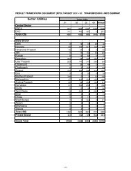
PROPOSED <strong>URTDSM</strong> IN INDIAN POWER SYSTEM<br />
List of PMU and PDCs to be installed at various substations in <strong>Central</strong> & <strong>State</strong> utilities<br />
as part of <strong>URTDSM</strong> is tabulated as under:<br />
Region Sub‐stations No of feeders PMU<br />
Nodal<br />
PDC MPDC SPDC<br />
Main &<br />
Back‐up<br />
NLDC<br />
ISTS STU ISTS STU ISTS STU<br />
NR 83 96 434 435 227 231 6 9 1<br />
WR 60 76 520 415 267 216 11 4 1<br />
ER 51 44 395 199 202 105 4 5 1<br />
SR 60 71 348 289 183 152 6 4 1<br />
NER 18 22 95 69 50 36 0 3 1<br />
Total 272 309 1792 1407 929 740 27 25 5<br />
581 3199 1669 57 2<br />
In addition to above, Remote console at each RPC(5) , UT(3) ,Sikkim (1), NTMC(2)<br />
,CEA(1) & NER <strong>State</strong>s(4) ,Total 16 Remote consoles are proposed.
III<br />
Report on <strong>URTDSM</strong><br />
Based on the availability of existing Fibre Optic(FO) communication link as well as FO<br />
link under implementation, it is proposed that implementation may be undertaken in<br />
two(2) phases; Phase-1 where substations with FO link would be available by 2014-15<br />
and; Phase-2 in balance substations where separate FO link to be established. Details<br />
are tabulated as under:<br />
N R‐PH‐1 N R‐PH‐II PDC<br />
S/st Feeder PMU S/st Feeders PMU<br />
Nodal<br />
PDC MPDC SPDC<br />
UP 17 82 44 7 28 15 1 1<br />
Rajasthan 8 42 24 17 61 35 1 1<br />
Himachal Pradesh 0 0 0 3 6 3 0 1<br />
Uttrakhand 1 2 1 5 16 8 0 1<br />
Haryana 3 21 11 11 46 23 0 1<br />
Delhi 3 18 9 4 14 7 0 1<br />
J&K 0 0 0 1 2 1 0 1<br />
Punjab 3 22 11 7 38 19 0 1<br />
BBMB 6 37 20 0 0 0 4 1<br />
CS 74 394 206 9 40 21 1<br />
Total 115 618 326 64 251 132 6 9 1<br />
SR‐PH‐I SR‐PH‐II<br />
Nodal<br />
PDC<br />
S/St Feeders PMU S/St Feeders PMU PDC MPDC SPDC<br />
Andhra Pradesh 10 61 32 18 60 32 2 1<br />
Karnataka 1 8 4 18 65 33 0 1<br />
Tamilnadu 3 14 7 13 49 27 0 1<br />
Kerala 2 7 4 6 25 13 0 1<br />
<strong>Central</strong> 57 338 178 3 10 5 4 1<br />
TOTAL 73 428 225 58 209 110 6 4 1<br />
WR‐PH‐I WR‐PH‐II<br />
Nodal<br />
PDC<br />
S/ST Feeders PMU S/ST Feeders PMU PDC MPDC SPDC<br />
MAHARASTRA<br />
MADHYA<br />
4 34 18 26 128 65 2 1<br />
PRADESH 8 57 30 6 30 16 1 1
IV<br />
Report on <strong>URTDSM</strong><br />
CHATTISGARH 3 21 11 1 4 2 0 1<br />
GUJARAT 3 23 12 25 118 62 2 1<br />
CENTRAL 49 456 234 11 64 33 6 1<br />
Total 67 591 305 69 344 178 11 4 1<br />
ER‐PH‐I ER‐PH‐II<br />
Nodal<br />
PDC<br />
S/st Feeders PMU S/st Feeders PMU PDC MPDC SPDC<br />
WEST BENGAL 9 40 22 9 40 20 0 1<br />
DVC 12 66 34 0 0 0 1<br />
ORISSA 6 30 16 4 10 6 0 1<br />
BIHAR 1 6 3 0 0 0 0 1<br />
Jharkhand 3 7 4 0 0 0 0 1<br />
CS 51 395 202 0 0 0 4 1<br />
Total 82 544 281 13 50 26 4 5 1<br />
NER‐PH‐I NER‐Ph‐II PDC<br />
S/St Feeders PMU S/st Feeders PMU<br />
Nodal<br />
PDC MPDC SPDC<br />
ARUNACHAL<br />
PRADESH 1 4 2 3 8 4 * 1<br />
Assam 4 20 11 10 27 14 0 1<br />
TRIPURA 0 0 0 1 2 1 *<br />
MEGHALAYA 0 0 0 2 6 3 * 1<br />
NAGALAND 0 0 0 1 2 1 *<br />
CENTRAL 9 69 36 9 26 14 1<br />
TOTAL 14 93 49 26 71 37 0 3 1<br />
Grand Total 351 2274 1186 230 925 483 27 25 5<br />
As a part of capacity building activity under <strong>URTDSM</strong> Phase-1 implementation, training<br />
programs are proposed.<br />
METHODOLOGY OF IMPLEMENTATION<br />
It is proposed that <strong>URTDSM</strong> project may be implemented in two (2) phases, as<br />
described under:
V<br />
Report on <strong>URTDSM</strong><br />
Phase-1: Placement of 1186 nos. PMUs at all lines in HVDC terminal stations, 400kV &<br />
above voltage level S/s, generating station stepped up at 220kV level & above<br />
where Fibre Optic(FO) cable along with communication equipment is either<br />
existing or being implemented by 2014-15.<br />
Placement of Nodal PDC (27 nos) at strategic sub-station, Master PDC<br />
(25nos) at SLDCs, Super PDC (5) at RLDCs, 2 No PDC at Main & Backup<br />
NLDC, Remote console at each RPC(5) , UT(3) ,Sikkim , NTMC(2),CEA(1) &<br />
NER <strong>State</strong>s(4) ,Total 16 .<br />
Broad Estimated Cost: Rs 169.82 Cr<br />
Implementation time: Progressively by 2014-15<br />
Development of Analytics for various applications using PMU data shall be<br />
taken up in parallel.<br />
Phase-2: Placement of balance 483 nos. PMUs at all HVDC terminal stations, 400kV &<br />
above voltage level S/s, generating station stepped up at 220kV level & above<br />
along with provision of Fibre Optic connectivity and communication<br />
equipments.<br />
Broad Estimated Cost: Rs 185.57 Cr including estimated communication<br />
system (Fibre Optic & communication terminals) cost: Rs. 116.10 Cr.<br />
• Estimated cost of <strong>URTDSM</strong> Phase-1 for WAMS: Rs. 169.82 Cr.<br />
• Estimated cost of <strong>URTDSM</strong> Phase-2 for WAMS: Rs. 69.47 Cr.<br />
� Total cost of WAMS (Ph-1 & 2) : Rs. 239.29 Cr.<br />
• Estimated cost of communication system under Phase-2: Rs. 116.10 Cr
VI<br />
Report on <strong>URTDSM</strong>
1.1 BACKGROUND<br />
Report on <strong>URTDSM</strong><br />
Chapter-1<br />
Introduction & Synchrophasor<br />
Indian power system is spreading at a fast pace to meet the growing requirement. In<br />
order to facilitate optimal utilization of unevenly distributed energy resources,<br />
strengthening of regional grids through inter-<strong>State</strong>/regional system is taking place<br />
continuously. Out of the five(5) regional grids, four(4) grids viz Northern, Western,<br />
Eastern and North-Eastern regions with capacity of about 137 GW have been<br />
synchronized with one another while the remaining Southern grid (49 GW) is<br />
expected to be synchronized by 2014.<br />
Widely spreading grid has also increased the complexity towards monitoring and<br />
control of such large grid. Significant quantum of power exchange among the regions<br />
triggered by Short-term Open Access, at times leads to congestion in certain<br />
corridors. Factors like seasonal loads, effects of weather and critical events also led<br />
to complex operating scenarios like fast changing power flow patterns coupled with<br />
significant loading upto emergency level etc. As per Indian electricity grid code each<br />
<strong>State</strong>/DISCOM is responsible for maintaining its load generation balance. Frequency<br />
is allowed to vary under specified band. Flexibility in frequency led to over drawal,<br />
under drawal, over generation and under generation by the utilities leading to over<br />
loading of lines and rise and dip of voltages in the grid. The excessive penetration of<br />
renewable generation due its unpredictability, variability and intermittency will also<br />
pose challenges in operation of the grid. Under such complexities, carrying out<br />
security assessment on real time basis and responding to contingencies are critical<br />
for maintaining reliability and stability of the grid.<br />
Recent advances in measurement, communications and analytic technologies have<br />
produced a range of new options. In particular, wide area measurement systems<br />
(WAMS) have come to the fore as a means to address not just immediate reliability<br />
concerns but also operations issues like enhancing transfer capability in real time,<br />
advanced automatic corrective actions like adaptive islanding, blocking/de-blocking<br />
1
Report on <strong>URTDSM</strong><br />
of distance relay zones under power swings, better visualization through state<br />
measurements, decision support tools etc.<br />
The existing SCADA/EMS provides only the steady state view of the power system.<br />
These systems take a minute to deliver a snap shot of a system whose characterstic<br />
are changing very fast. In contrast to the conventional SCADA system where RTUs<br />
are used to acquire voltage, current and frequency, Wide Area Monitoring system<br />
acquire current, voltage (both magnitude and phase angle) and frequency<br />
measurement by phasor measurement and are also time synchronised via Global<br />
Positioning System (GPS) receiver to a time resolution of 1 micro sec. so that <strong>Real</strong><br />
<strong>Time</strong> <strong>Dynamic</strong> <strong>State</strong> <strong>Measurement</strong>s/Monitoring of System across the widely spread<br />
grid is possible. The wide area measurement facilitates better, faster analyses of grid<br />
conditions, which in turn provide operators with more time and more options to<br />
preserve system stability. It also represents a quantum leap in the quality of data on<br />
which everyday operational decisions are based. This will help in maintaining grid<br />
safety and security and will be a step towards intelligent and self healing grid.<br />
Deployment of this technology in Indian Power System has been envisaged in the<br />
Report of Working Group on Power for 11th Plan, Government of India as well as in<br />
National Electricity Policy.<br />
1.2 PHASOR & SYNCHROPHASOR TECHNOLOGY<br />
A phasor is a complex number that represents both the magnitude and phase angle<br />
of the sine waves found in AC system as shown in figure 1.1.<br />
Fig.1.1: Phasor representing magnitude & phase angle of sine wave of voltage or current.<br />
Phasor measurements that occur at the same time are called "synchrophasors" and<br />
can be measured precisely by the Phasor measurement units (PMUs). PMU<br />
2
Report on <strong>URTDSM</strong><br />
measurements are taken at high speed typically 25 or 50 samples per second –<br />
compared to one every 4 to 10 seconds using conventional technology. Each<br />
measurement is time-stamped according to a common time reference. <strong>Time</strong><br />
stamping allows phasors at different locations to be time-aligned (or synchronized)<br />
thus providing a comprehensive view of the entire grid at central location.<br />
A typical PMU installation as a part of wide area monitoring system (WAMS) network<br />
consists of phasor measurement units (PMUs) dispersly placed throughout the<br />
electricity grid at strategic locations in order to cover the diverse footprint of the grid.<br />
A Phasor Data Concentrator (PDC) at central location collects the information from<br />
PMUs and provides alert and alarm for emergency situations as well as facilitates<br />
development of different types of analytics for smooth operation of grid on real time<br />
basis. The PMU data is also transmit to Supervisory Control and Data Acquisition<br />
(SCADA) system after time aligning the same. The WAMS technology requires high<br />
bandwidth communication network for rapid data transfer matching the frequency of<br />
sampling of the PMU data.<br />
1.3 SYNCHROPHASOR APPLICATION WORLDWIDE<br />
Worldwide many utilities from North America, Europe, China, Russia and Brazil have<br />
started using/developing the new PMU applications to harness the potential benefits<br />
of this emerging technology in operating very large electrical grids.<br />
In 2006, China's Wide Area Monitoring Systems (WAMS) for its six(6) grids had 300<br />
PMUs installed mainly at 500kV and 330kV substations and power plants. Presently<br />
China has installed more than 1000 PMUs in their Grid. By 2012, China plans to<br />
have PMUs at all 500kV substations and all power plants of 300MW and above<br />
In U.S there are ten(10) synchrophasor projects underway involving 57 utilities and<br />
grid operators across the country and installing about 850 networked PMUs. By<br />
2013, the devices will be operating in nearly all regions of the country. The Eastern<br />
Interconnect Phasor Project (EIPP) (now known as the North American<br />
Synchrophasor Initiative, or NASPI), has over 40 connected phasor measurement<br />
units collecting data into a "Super Phasor Data Concentrator" system centered at<br />
Tennessee Valley Authority (TVA). Southern California Edison is successfully using<br />
3
Report on <strong>URTDSM</strong><br />
synchrophasors today to trigger some automated grid protection functions on their<br />
system<br />
Oklahoma Gas & Electric Co.(OG&E), USA uses synchrophasor technology as a<br />
practical tool to locate and solve real-world operating problems. The utility has added<br />
more than 100 PMUs to the system, which provided monitoring almost 30% of its<br />
transmission grid. From the synchrophasor data, OG&E can determine if a<br />
disturbance is cleared by high-speed or step-distance (delayed) tripping. The data is<br />
being used to locate the source of event disturbance and proceed with an<br />
investigation. Another valuable use of synchrophasor data is the detection of<br />
equipment failure, most of which is not detectable by SCADA system. System<br />
stability assessment is being carried out using synchrophasor data especially<br />
capturing the intricacies of an interconnected system like low frequency oscillations<br />
due to generation control problem or other reasons. The benefit of PMU<br />
measurements at the point of wind farm interconnection facilitates customer to<br />
receive clean power (in terms of voltage fluctuation/flicker) while maintaining the<br />
level of system stability necessary for reliable power system operation.<br />
Apart from above nations, other countries like South Africa, Brazil, USSR, Western<br />
Electricity Coordinating Council (WECC) whose service territory extends from<br />
Canada to Mexico and some European countries have deployed/ planning to deploy<br />
a large no. of PMUs in their system.<br />
4
2.1 PHASOR MEASUREMENT PRACTICE IN INDIA<br />
Report on <strong>URTDSM</strong><br />
Chapter-2<br />
Phasor <strong>Measurement</strong> in India<br />
National and Regional Load Despatch Centres in India are being operated by Power<br />
Systems Operation Corporation(POSOCO), a wholly owned subsidiary of<br />
POWERGRID, whereas <strong>State</strong> Load DespatchCentres are operated by respective<br />
<strong>State</strong> utilities. They are equipped with <strong>State</strong>-of-the-Art SCADA/EMS system.<br />
Telemetry from different sub-stations and power plants are being received at each<br />
SLDC/RLDC and subsequently to NLDC which are being utilized in day to day<br />
operations of the regional grid.<br />
Synchronous Interconnection of regional grids forming large interconnected system<br />
(for example formation of NEW grid ) and various changes undergoing in the Indian<br />
power industry requires better situational awareness of the grid event and<br />
visualization at the control center for real time system operation. Knowledge about<br />
the angular separation between different nodes of a power system has always been<br />
of great interest for power system operators. Phase angle measurement is<br />
commonly used in auto synchronization of generating stations and check<br />
synchronization relays used at substations for closing of lines as well as during<br />
three-phase auto-reclosing. All these applications are at the local level.<br />
Prior to the introduction of Phasor <strong>Measurement</strong> Units (PMUs) at control centre level<br />
this analogue value is normally not considered as measurable in SCADA system and<br />
hence does not form a part of the SCADA measurement. However SCADA<br />
technology does provide an estimate of the relative phase angle difference (with<br />
respect to a reference bus) through the <strong>State</strong> Estimator. The <strong>State</strong> estimator uses<br />
the SCADA inputs (analogue and digital measurands) to estimate the system state<br />
viz. node voltage and angle.<br />
Information about phase angle difference between two different nodes in a power<br />
system has also been calculated based on the real time power flow between the<br />
5
Report on <strong>URTDSM</strong><br />
nodes, bus voltages and network reactance using standard equation δ = sin -1<br />
(P*X/V1*V2). Angular information at control centre is also obtained by placing phase<br />
angle transducer at strategic locations and interfacing it in existing SCADA system<br />
However all the above methods of calculation of phase angle difference have<br />
limitations due to resolution, data latency, updation time and data skewedness.<br />
Update time in the SCADA system is considerably large (up to 10-15 seconds) for<br />
visualizing and controlling the dynamics of power system. The real time angular<br />
measurement in the power system avoids above uncertainties and can be relied on<br />
to assess the transmission capability in real time which is very crucial in efficiently<br />
operating the present electricity market mechanism.<br />
PMUs are able to measure what was once immeasurable: phase difference at<br />
different substations. A pilot project was implemented in Northern Region (NR) to<br />
assess the potential of PMU/synchrophasor measurements. Experienced gained<br />
with this pilot project is described in the following paragraph.<br />
2.2 PMU PILOT PROJECT IN NORTHERN REGION GRID<br />
The PMU pilot project implemented in NR consists of PMUs along with GPS installed<br />
at selected 9 substations in the grid(Refer Fig-2.1). A Phasor Data Concentrator and<br />
other associated equipment are placed at Northern Regional Load Despatch Centre<br />
(NRLDC) located at New Delhi as shown in Fig 2.2.<br />
Fig 2.1: Locations of PMUs in the NR<br />
Fig 2.2: Hardware Architecture of PMU Pilot<br />
Project<br />
6
Report on <strong>URTDSM</strong><br />
PMUs have been installed at Vindhychal HVDC, Dadri HVDC, 400kV S/s at Kanpur,<br />
Moga, Agra, Hisar, Kishenpur, Bassi and KarchamWangtoo. PMUs are presently taking<br />
voltage & current inputs. Voltage inputs have been provided from CVT/PT of the main<br />
bus of the substation. PDC and associated equipments installed at NRLDC is shown in<br />
Fig 2.3. PMU along with GPS as installed at one of the location are shown in Fig 2.4.<br />
Fig 2. 3: PDC and other Equipments at Fig 2. 4: PMU and GPS at Substation<br />
NRLDC<br />
Phasor data at each PMU is being sampled at 25 samples per second with GPS time<br />
stamping and transferred to Phasor Data Concentrator (PDC) provided at NRLDC<br />
through dedicated 64kbps fiber optic communication link. The phasor data received<br />
from all the locations is merged and time aligned in the PDC. The time aligned data<br />
from PDC is provided to operator console for visualization.<br />
The visualization display on an operator console is shown in Fig 2.5 to 2.8. PDC data is<br />
also fed to a data historian provided at NRLDC. Data from historian can be made<br />
available to external database through ODBC (Open Database Connectivity) and<br />
spreadsheet for further analysis. PDC has also been provided with OPC (OLE for<br />
Process Control) server in order to transfer real time phasor data to existing SCADA<br />
system. Communication between PMUs at remote locations and PDC at central location<br />
takes place as per IEEE C37.118 standard.<br />
7
2.3 UTILIZATION OF PMU DATA<br />
Fig 2.5 Fig-2.6<br />
Fig 2.7 Fig 2.8<br />
Report on <strong>URTDSM</strong><br />
The data from synchrophasor is a huge leap from the data from SCADA system. An<br />
accurate measurement of voltage and current phasors for four locations in the grid is<br />
now available with a resolution of 40 ms i.e, 25 samples per second. The precise<br />
relative phase angle separation can also be seen. Apart from these angular separation<br />
other important system monitoring parameters such as frequency, rate of change of<br />
frequency, positive sequence phase voltages and power flow are also available. Even<br />
the limited exposure with synchrophasor data has been a revelation in terms of its<br />
8
Report on <strong>URTDSM</strong><br />
potential for future applications. The data is being examined closely for drawing<br />
inferences. Some of the inferences are as under:<br />
• It has been found that even within the synchronous system there could be difference<br />
Hz<br />
50.00<br />
49.80<br />
49.60<br />
49.40<br />
49.20<br />
49.00<br />
in frequency (few hundred microseconds) at various locations. This difference is<br />
pronounced during system transients such as tripping of generating units. Refer fig.<br />
2.9 & 2.10 for plots of frequency and rate of change of frequency based on PMU<br />
data during the incident of 2000 MW loss of generation at Rihand on 1st June 2010.<br />
Such difference in frequency was not visualized through SCADA system due to 10<br />
second data. At specific instance of 2000MW generation loss, it was observed that<br />
frequency in different locations oscillated differently for about 1 Sec before settling<br />
down to common frequency. The amplitude of oscillation was large near fault<br />
location.<br />
Frequency<br />
23:49:37.000 23:49:39.400 23:49:41.800 23:49:44.200 23:49:46.600 23:49:49.000<br />
<strong>Time</strong><br />
Vindhyachal<br />
Kanpur<br />
Dadri<br />
Moga<br />
1.50<br />
1.00<br />
0.50<br />
0.00<br />
‐0.50<br />
‐1.00<br />
‐1.50<br />
‐2.00<br />
df/dt<br />
23:49:37.000 23:49:39.400 23:49:41.800 23:49:44.200 23:49:46.600 23:49:49.000<br />
<strong>Time</strong><br />
Vindhyachal<br />
Fig 2.9: Absolute Frequency Fig 2.10: Rate of Change of Frequency<br />
• High rate of change in frequency of the order of +1 Hz to 1.5 Hz were also observed<br />
during initial fault period which disappears after 100 to 120 millisecs. Because of this<br />
system behavior, delays of 8 to 10 cycles were introduced in measurement time of<br />
df/dt relays in NR to prevent load shedding during initial high df/dtvalues.The values<br />
of df/dt have helped in identifying the wrong df/dt relay setting and mal-operations of<br />
these relays.<br />
• The sags and swells in voltage which were not observable in SCADA are now<br />
observable through Synchrophasor data. Likewise the imbalance in voltage and<br />
current between different phases can be clearly seen Refer Fig 2.11& 2.12<br />
Kanpur<br />
Dadri<br />
Moga<br />
9
Voltage‐kV Thousands<br />
228<br />
227<br />
227<br />
226<br />
226<br />
225<br />
225<br />
9:30:00.000 9:30:01.400 9:30:02.800 9:30:04.200 9:30:05.600<br />
<strong>Time</strong><br />
9:30:07.000 9:30:08.400 9:30:09.800<br />
Current ‐ Ampere<br />
660<br />
640<br />
620<br />
600<br />
580<br />
560<br />
540<br />
Report on <strong>URTDSM</strong><br />
520<br />
9:30:00.000 9:30:01.400 9:30:02.800 9:30:04.200 9:30:05.600<br />
<strong>Time</strong><br />
9:30:07.000 9:30:08.400 9:30:09.800<br />
Fig 2.11: Imbalnce in phase voltage Fig 2.12: Imbalance in phase current<br />
• During grid events the operators are able to see the fault current, voltage, protection<br />
Voltage kV Thousands<br />
system response time, fault clearance time etc. as shown in Fig 2.13 & 2.14. Such<br />
information are very useful for disturbance analysis and better situational awareness<br />
in the real time system operation<br />
260<br />
240<br />
220<br />
200<br />
180<br />
160<br />
140<br />
120<br />
Voltage profile at Dadri during tripping of Bus -II at Dadri at 15:33 Hrs on 8th July 2010<br />
(PMU 40ms Data plot)<br />
100<br />
15:33:48.000 15:33:48.400 15:33:48.800 15:33:49.200 15:33:49.600 15:33:50.000<br />
<strong>Time</strong><br />
Fault Cleared with in 80<br />
ms<br />
Thousands<br />
kV<br />
240<br />
235<br />
230<br />
225<br />
220<br />
215<br />
Dadri Voltage Profile observed during incident of generation loss due to tripping of all<br />
units at Panipat TPS on 12/07/2010 at 18:16Hrs (40ms data plot)<br />
210<br />
18:16:00.040 18:16:12.040 18:16:24.040 18:16:36.040<br />
<strong>Time</strong><br />
18:16:48.040 18:17:00.040 18:17:12.040<br />
Fig 2.13 Fig 2. 14<br />
• In the Northern region, during the foggy winter nights transmission lines often<br />
autorecloses and trips due to flashover across insulators. Information about<br />
autoreclosure of transmission lines can be indirectly inferred from the plots of<br />
df/dt(Refer Fig 2.15). Such information was found to be very useful in better<br />
situational awareness and operational planning in the real time.<br />
10
Fig 2.15: Autoreclosure detected through PMU data<br />
Report on <strong>URTDSM</strong><br />
• The phase angle across nodes has helped in determining the stress in the grid and<br />
its proximity to instability. The proximity to instability is measured w.r.t predetermined<br />
stability threshold limit. With this the transfer capability of the corridor can be re-<br />
assessed in the real time. Following inferences were derived from the phasor data<br />
measurement across the boundaries:<br />
1. The phasor angle is sensitive to variation in load profile, generation dispatch and<br />
network topology.<br />
2. It has correlation with power flow across boundaries.<br />
3. During contingencies the magnitude of variation increases sharply.<br />
4. Any system separation or disturbances within or across the region were quickly<br />
reflected in angular separation trend.<br />
• Oscillations observed through PMU have been found to be very useful in validating<br />
the transfer capability, tuning the SPS settings, identifying the need for PSS tunning<br />
etc. (Refer fig 2.16 & 2.17).<br />
11
H<br />
z<br />
50.12<br />
50.10<br />
50.08<br />
50.06<br />
50.04<br />
50.02<br />
50.00<br />
49.98<br />
49.96<br />
49.94<br />
49.92<br />
Frequency profile on 16th July 2011 from 04:28 ‐ 04:31 Hrs<br />
(40ms data plot)<br />
4:28:57.240<br />
4:29:07.560<br />
DADRI.FREQ MOGA.FREQ HISSAR.FREQ<br />
49.90<br />
4:28:53.000 4:28:57.000 4:29:01.000 4:29:05.000<br />
<strong>Time</strong><br />
4:29:09.000 4:29:13.000 4:29:17.000<br />
Fig 2.16 Fig 2.17<br />
Report on <strong>URTDSM</strong><br />
• Delay in operating time of SPS for reliable evacuation of additional 2x250 MW<br />
generation in the Baspa Hydro, Jhakri Hydro and KarchamWangtoo Hydro complex<br />
could be detected only through the PMU measurements available at NRLDC that<br />
was suitably corrected.<br />
• Oscillations observed through PMU in the entire NEW grid system, during high<br />
loading of 400 kV Tehri-Merrut line, when one of this D/C line was out for<br />
construction of Koteshwar evacuation facilitated the need for proper tuning of PSS<br />
at Tehri end to avoid in major disturbances / damage to generators.<br />
• Information obtained through PMUs has been found to be very helpful in monitoring<br />
the performance of protection system in the grid. Some of the discrepancies in<br />
overvoltage settings and unnecessary overvoltage tripping could be detected<br />
through the PMU, those were later rectified.<br />
• PMU measurement has also been found to be very useful in validating the real time<br />
online SCADA network model and offline network models<br />
12
3.1 EXISTING SCADA/EMS OPERATION<br />
Report on <strong>URTDSM</strong><br />
Chapter-3<br />
Existing Operation Tool in System Operation<br />
The Supervisory Control and Data Acquisition (SCADA)/Energy Management Systems<br />
(EMS) are based on distributed architecture incorporating open system features. The<br />
communication system consisting of Fiber Optic and Microwave provide faster and<br />
reliable data transfer and voice communication between Control Centers.<br />
SCADA/EMS system is hierarchical in nature having four levels of hierarchies. At<br />
national level, SCADA/EMS systems of all five (5) RLDCs report to NLDC. Data from<br />
each RLDC is transmitted to NLDC in real time on dedicated communication lines. At<br />
regional level, RLDC coordinates all the inter-state activities of SCADA/EMS systems of<br />
SLDCs of a region. SCADA systems of all the Sub-LDCs of a state report to the SLDC<br />
of that state. The hierarchy of grid management is shown in Fig. 3.1<br />
Fig 3.1: Hierarchy in Grid Operation management<br />
Main components of the SCADA system at RLDC and SLDC are SCADA/EMS server<br />
and ICCP server. SCADA/EMS or data server maintain all data acquired from other<br />
13
Report on <strong>URTDSM</strong><br />
SLDCs etc and make it available to display and reporting. ICCP (Inter Control-center<br />
Communication Protocol) server acts as gateway for transfer of data between SLDCs<br />
and between RLDC and SLDCs. SCADA/EMS system at RLDC, SLDC and Sub-LDC<br />
are based on distributed architecture and open standards. The major functions of the<br />
SCADA/EMS system are summarized below:-<br />
SCADA Functions<br />
• Data acquisition from RTUs<br />
• Supervisory control of power system element (not being used at present)<br />
• Historical data storage and retrieval<br />
• Sequence of events recording<br />
EMS Functions<br />
• Operation Monitoring<br />
• Operation Scheduling-Load Forecasting, Hydro Scheduling, Interchange<br />
Scheduling<br />
• Network Analysis - <strong>State</strong> Estimation, Bus Load Forecast, Contingency Analysis,<br />
Optimum Power Flow<br />
3.2 LIMITATION IN EXISTING SCADA/EMS<br />
In existing SCADA/EMS the field data is obtained from RTUs. As the RTUs are<br />
scattered in large geographical Area, the data from a cluster of RTUs are concentrated<br />
at Sub-LDC level and sent to SLDC and then to RLDC by wide band communication as<br />
shown in the Fig 3.2. Thus the data updation time at the main control centre is having a<br />
latency of few seconds ranging from 10 to 30 seconds. Based on this updation, the<br />
state of the power system is estimated using state estimator every few minutes or on<br />
operators demand. But this estimation has its own limitations because data from<br />
different locations has time skewed as the data is not time synchronized. Some of the<br />
data is reported directly by RTU and some is updated through ICCP. Even the data<br />
coming from different RTU/ICCP comes in different scan group and through different<br />
channels of communication (Fibre Optic, Digital Microwave, PLCC). Thus at times the<br />
estimate does not converge due to time skew in measured values or wrong parameter<br />
or telemetry failure and in even when it converges the accuracy is low.. Due to slow rate<br />
14
Report on <strong>URTDSM</strong><br />
of data update at times, the fluctuations are observed in the network through SCADA<br />
system due to fault/power swing/ loss of generation/load but the operators find it difficult<br />
to accurately pin point the cause and location of problems.<br />
SKEW<br />
In sec<br />
25<br />
20<br />
15<br />
30<br />
Data Flow Latency<br />
2 seconds<br />
ERLDC WRLDC NRLDC SRLDC NERLDC<br />
SLDC SLDC SLDC<br />
12-15 seconds<br />
2 seconds<br />
NLDC<br />
NLDC<br />
2 seconds<br />
SUB LDC SUB LDC SUB LDC<br />
12-15 seconds<br />
12-15<br />
secs<br />
12-15 seconds<br />
12-15 seconds<br />
RTU RTU RTU<br />
RTU<br />
RTU<br />
1 Plant/Sub<br />
Station Level<br />
Fig 3.2: Data flow time in SCADA<br />
National<br />
Level<br />
Region<br />
Level<br />
<strong>State</strong> HQ<br />
Level<br />
Group of<br />
Distt. Level<br />
3.3 COMMUNICATION INFRASTRUCTURE<br />
The communication network built under ULDC (<strong>Unified</strong> Load Desptch &<br />
Communication) project consists of Fiber Optic, Digital Microwave (DMW) and PLCC<br />
based Communication System. In August, 2008, DoT intimated that 2.3 to 2.4 GHz<br />
frequency band presently being used for microwave communication will be allocated for<br />
Broadband Wireless Access (BWA.) services as per GOI guidelines. Hence, the users<br />
of 2.3 – 2.4 GHz band are required to vacate the band. Accordingly, establishment of<br />
Fibre Optic networks under Microwave replacement projects have been undertaken for<br />
NR, SR, ER & NER and approved by respective RPCs which is under implementation.<br />
In addition, Fibre Optic links are being implemented under expansion projects for WR,<br />
NR, ER & SR.<br />
15
Report on <strong>URTDSM</strong><br />
As mentioned earlier, each PMU requires minimum 64 kbps bandwidth with Ethernet<br />
interface which is presently not available at most of the locations. Therefore existing<br />
communication terminal equipments will need interface cards.<br />
As per the standard for communication data from PMU, a IEEE C37.118 message<br />
consisting one(1) 3-phase Voltage Phasor, two(2) 3-phase Current Phasors, one(1)<br />
Frequency, one(1) Rate of change of Frequency and 8 digital signals need a bandwidth<br />
of around 48.8 kbps at sampling rate of 50 samples per second. Therefore, practically<br />
to begin with each PMU shall require a band width of 64kbps which can accommodate<br />
measurement on maximum two feeders. The existing/planned wide band Fiber Optic<br />
connectivity at substations can be used to transfer PMU data to control centres with the<br />
addition of suitable interface cards. The bandwidth requirement would increase<br />
significantly if more no of feeders are added in the PMU. Further when control functions<br />
are developed and deployed, effective implementation will require the latency of<br />
communication network between the points involved in transfer of control signals should<br />
be less than 100 ms. A PLCC network does not have such high bandwidth and low<br />
latency. Looking further at physical redundancy and enhanced reliability needs for<br />
Power System operation, Optical Ground Wire (OPGW) based Fiber Optic<br />
Communication ideally meets the requirement of Communication media for WAMS<br />
technology. The Fibre Optic network is required to be extended to all those substations<br />
and power plants where PMUs are to be installed.<br />
16
4.1 WIDE AREA MONITORING SYSTEM (WAMS)<br />
Report on <strong>URTDSM</strong><br />
Chapter-4<br />
WAMS for <strong>URTDSM</strong><br />
A WAMS (Wide Area Monitoring Systems) using Phasor measurement unit (PMUs) is<br />
advanced measurement system that provides synchronized measurements at subsec<br />
rate. The WAMS technology provides phasor measurements in terms of amplitude and<br />
phase angle of voltage and current over a widely spread grid.<br />
The components of WAMS consists of Phasor <strong>Measurement</strong> Units (PMUs), Phasor<br />
Data Concentrators (PDCs), Visualization aids, Application and Analysis modules, Data<br />
archiving and storage etc. The basic infrastructure of WAMS technology is PMU, wide-<br />
band communication and PDC units.<br />
4.2 MEASUREMENT PROCESS IN WAMS<br />
Bus voltage and current phasors in transmission line is measured directly through PMU<br />
in terms of amplitude as well as phase angle. Input to the PMU is taken from bus PT<br />
and line CT at the substation including time signal through GPS. Phase angle is<br />
measured relative with GPS frame. The standard PMU presently available in market is<br />
capable of taking two sets of three phases current, one set of three phase voltage and 8<br />
digital inputs. Thus, current signals from any 2 feeders can be connected to one<br />
PMU.Based on this number of PMUS in a station is calculated. Output from PMUs in a<br />
particular station (sending station) is transmitted through a LAN switch and router to<br />
PDC.<br />
A Phasor Data Concentrator (PDC) is used to collect data from multiple PMUs and<br />
other PDCs. A PDC also aligns data by time tag to create a time synchronized dataset,<br />
and transmit this dataset to other information system. All data concentrators are<br />
connected locally to the respective host computer, printers and operators console via<br />
Ethernet. PDCs can also filter the data so that it can be fed to applications which use<br />
slow sample data such as SCADA system. The PDC is capable of correlating the time<br />
17
Report on <strong>URTDSM</strong><br />
tag phasor data; conforming to phasor standard 37.118 for both input and output data<br />
stream, verify the integrity and completeness of data stream. Depending on the roles of<br />
the PDC, they are equipped with different functions. Visualization tools are proposed at<br />
Master, Super and PDC at NLDC. Historian capabilities shall be based on volume of<br />
data to be handled by the PDC. A typical data flow arrangement from field level to<br />
control centre is shown at Fig 4.1.<br />
TRANSMISSION<br />
ONE LINE<br />
PT<br />
CT<br />
PMU<br />
GPS<br />
SWITCH<br />
Analog:V,Φ,I , f , df/dt<br />
Status: CB , Iso<br />
SUB-STATION<br />
Typical Information Flow and Data Collection in URTDMS<br />
ROUTER ROUTER<br />
ROUTER<br />
Fibre Optic<br />
based WAN<br />
Workstation<br />
Printer<br />
SWITCH<br />
Nodal PDC<br />
GPS<br />
Historian<br />
NODAL PDC AT<br />
INTERMEDIATE S/S<br />
Fibre Optic<br />
based WAN<br />
Workstation<br />
Firewall<br />
SCADA LAN<br />
Fig 4.1: Typical Information Flow and Data Collection<br />
SWITCH<br />
To NLDC PDC<br />
PDC<br />
Historian<br />
Printer<br />
Printer<br />
MPDC/SPDC AT SLDC/RLDC<br />
In order to maintain ease of data flow as well as computational process, it is proposed<br />
that PMU measured data from a number of substations in a <strong>State</strong> are to be pooled and<br />
send it to a Nodal PDC located at strategic location in the <strong>State</strong>. It is proposed to use<br />
one PDC (called Nodal PDC) for approximately 50 to 60 PMUs in any state. No Nodal<br />
PDC will communicate with the PMUs installed in any other state. Data from number of<br />
Nodal PDCs are to be sent to a Master PDC located at respective SLDC and in turn to<br />
Super PDC located at respective RLDC. Data from ISTS points are to be sent directly to<br />
Super PDC (SPDC) at respective RLDC via Nodal PDC. Data from each SPDC are to<br />
be sent to National PDC located at NLDC. A schematic of the proposed interconnection<br />
arrangement is shown at Fig. 4.2.<br />
GPS<br />
18
UNIFIED REAL TIME DYNAMIC STATE MEASUREMENT SYSTEM HIERARCHY<br />
Remote Console<br />
at RPCs<br />
<strong>State</strong> Stns<br />
Router/switch<br />
PMU<br />
1<br />
Sub Stn A<br />
PMU<br />
n<br />
PDC at Back up<br />
NLDC<br />
Master PDC at SLDCs<br />
Nodal PDC at sub-station<br />
<strong>State</strong> Stns<br />
Router/switch<br />
PMU<br />
1<br />
Sub Stn 1<br />
PMU<br />
n<br />
Super PDC<br />
at RLDCs<br />
PDC at NLDC<br />
Nodal PDC at sub-station<br />
<strong>State</strong> Stns<br />
Router/switch<br />
PMU<br />
1<br />
Sub Stn m<br />
PMU<br />
n<br />
Remote Console<br />
at UT(3) & NER <strong>State</strong>s(4),<br />
Sikkim ,NTMC(2),CEA<br />
Centre Stns<br />
Router/switch<br />
PMU<br />
1<br />
Sub Stn B<br />
PMU<br />
n<br />
Fig 4.2: Hierarchy of <strong>Unified</strong> <strong>Real</strong> <strong>Time</strong> <strong>Dynamic</strong> <strong>Measurement</strong> System<br />
Report on <strong>URTDSM</strong><br />
Most programs for WAMS technology world over have three (3) stages of<br />
implementation. The first stage is to install PMU, PDC and collect/archive phasor data<br />
from important locations throughout the grid to determine the topology and operating<br />
limits. In Second stage, the data gathered along with real-time phasor and frequency<br />
measurements to calculate grid conditions using analytical functions to make<br />
suggestions to grid operator to keep grid stable and reliable. The final stage is to carry<br />
out all of the above functions automatically.<br />
In Indian Power System context, it is proposed to follow the similar philosophy i.e.<br />
installation of PMUs on substations at 400kV level and above in the <strong>State</strong> & <strong>Central</strong><br />
grids, all generating stations at 220kV level and above, HVDC terminals, important interregional/national<br />
connection points etc., provision of PDC at strategic sub-stations to<br />
collect the data of nearby PMUs, all SLDCs, RLDCs and NLDC along with visualization<br />
aids as a first phase. This shall facilitate a <strong>Unified</strong> <strong>Real</strong>-time <strong>Dynamic</strong> <strong>State</strong><br />
<strong>Measurement</strong>s (<strong>URTDSM</strong>) tool towards improved system operation. In the subsequent<br />
phases, development of software based analytic functions and automatic corrective<br />
actions will be undertaken.<br />
19
4.3 PHASOR DATA CONCENTRATOR (PDC)<br />
Report on <strong>URTDSM</strong><br />
The electrical parameters measured by a number of PMUs are to be collected by some<br />
device either locally or remotely, this function is performed by Phasor Data Concentrator<br />
(PDC). A PDC forms a node in a system where phasor data from a number of PMUs is<br />
collected, correlated and fed as a single stream to other applications. In a hierarical set<br />
up the PDCs can also be used to collect the data from number of down stream PDCs.<br />
PDC provides additional functions as under:<br />
• It performs quality checks on the phasor data and inserts appropriate flags<br />
• It checks disturbance flags and records files of data for analysis<br />
• It monitors the overall measurement system and provides a display and record of<br />
performance<br />
• It can provide a number of specialized outputs that can be interfaced with the other<br />
system e.g SCADA/EMS system.<br />
4.4 COMMUNICATION<br />
The Communication infrastructure is critical backbone in the architecture of a WAMS<br />
system. PMU devices are distributed over a wide area, covering various locations within<br />
the boundary of a power system. The PMU devices are then connected to one or many<br />
control centers over the communication network. Fibre Optic Communication network<br />
due to its high bandwidth offer low latency for communication between PMU to PDC<br />
and PDC to PDC. The Fibre Optic terminal equipments will have the provision of in-built<br />
Ethernet port. The Ethernet port shall be used in the communication network of WAMS<br />
for dedicated channels.. The existing SDH equipment will have Ethernet converter for<br />
converting from E-1 to Ethernet.<br />
The network architecture would then be composed of a main optical fibre backbone<br />
connected to the substation Router/Switch. In turn, the PMU can be connected to the<br />
substation through Switch and Switch. The PMU measurements are then transferred to<br />
a PDC, which time aligns the phasors. Block diagram of communication architecture<br />
between PMUs at the locations in substations and information exchange at the<br />
substation control room is shown at Fig 4.3.<br />
20
Sub Station<br />
Control<br />
Room<br />
Switchyard<br />
Area<br />
GPS<br />
Receiver<br />
PMU<br />
CT/PT<br />
2 No Bays<br />
GPS<br />
Receiver<br />
PMU<br />
CT/PT<br />
2 No Bays<br />
IEEE C 37.118<br />
Router<br />
Switch<br />
Report on <strong>URTDSM</strong><br />
GPS<br />
Receiver<br />
PMU<br />
CT/PT<br />
2 No Bays<br />
Fig. 4.3: Communication architecture between Substation PMUs & Control centre<br />
4.5 Nodal PDC, Master Phasor Data Concentrator (MPDC) & Super PDC<br />
A nodal PDC shall be located at strategic location in <strong>Central</strong> and <strong>State</strong> Sector to pool<br />
the data of PMUs installed in various sub-stations of that area. Approximately for 50 to<br />
60 PMUs one nodal PDC is planned. Nodal PDC is equipped with Historian for data<br />
storage. Master PDC will collect and correlate the required data from PMUs and Nodal<br />
PDCs under its area of operation. The Master PDC shall be located at the SLDC<br />
Control Center. It is proposed to have an analytical tool and visualization software<br />
package for all Master PDC. The Master PDC will also be connected to a central<br />
database for long-term archiving of the collected data for post disturbance analysis.<br />
Super PDCs are to be placed at each RLDC which will collect data from PMUs at ISTS<br />
stations and ISGS as well as from MPDC. The PDC at NLDC will collect information<br />
from all the five (5) Super PDCs at RLDCs. Remote console is proposed at each RPC<br />
and NTAMC for carrying out analysis/studies. The proposed WAMS architecture for<br />
<strong>Unified</strong> <strong>Real</strong> <strong>Time</strong> <strong>Dynamic</strong> <strong>State</strong> <strong>Measurement</strong>s (<strong>URTDSM</strong>) is shown at Fig. 4.4<br />
21
Field<br />
Devices<br />
Communication<br />
Media<br />
SLDC/RLDC<br />
MPDC/SPDC LAN<br />
Dual Monitor<br />
Workstation<br />
GP<br />
4.6 PANEL OF EXPERTS<br />
PMUs/Nodal<br />
PDC<br />
ROUTER<br />
Router cum<br />
Firewall<br />
Historian<br />
MPDC/SPD<br />
Fig 4.4 Architecture of MPDC<br />
Printers<br />
Report on <strong>URTDSM</strong><br />
A panel of experts headed by Prof. A.G.Phadke, Verginia Tech. University USA<br />
comprising members across the globe for implementation of WAMS Technology in<br />
Indian power system has been appointed. The views of experts are as under:<br />
1. The communication system for PMU should be based on Fiber Optics and should<br />
have physical route redundancy. The communication infrastructure strengthening<br />
should be taken on priority for PMU project.<br />
2. Sampling rates for the PMU to be as 25 samples per second but should have<br />
provision for 50 samples per second.<br />
3. Levels of hierarchies in the PMU data flow should be minimised to achieve least<br />
latency (100 Milli seconds).<br />
4. PMUs shall record minimum 1 set of 3-phase Bus voltages and 3-phase currents<br />
of all feeders.<br />
5. RLDC PDC needs to have the facility of data interface with SCADA/EMS system<br />
apart from collecting data from different PMUs.<br />
6. Work can be initiated on applications of PMU data in following areas :<br />
22
• Transfer Capability Assessment<br />
• Analysis of sustained oscillations<br />
• CT/CVT validation<br />
• Vulnerability of relay characteristic<br />
Report on <strong>URTDSM</strong><br />
4.7 PMU/PDC DEPLOYMENT PLAN<br />
In line with the forgoing discussions the requirement of PDCs and PMU has been<br />
estimated. The approach is presented as under:<br />
1. PMU will take one(1) 3 phase voltage, two(2) three phase currents, and 8 digital<br />
signals.The PMU will provide 3 phase positive sequence voltages as magnitude and<br />
angle,3 phase positive sequence currents magnitude and angle ,Frequency, Rate of<br />
change of frequency(df/dt) & Active and Reactive power may be derived either at<br />
PMUs or PDC from the measured values.<br />
2. Installation of PMU at each HVDC and 400kV & above substations in <strong>State</strong> and<br />
ISTS network<br />
3. PMU at generation switchyard at 220kV level and above<br />
4. 220kV Inter-regional transmission lines<br />
5. One(1) Nodal PDC at strategic location where number of PMUs are more than<br />
forty(40)<br />
6. One(1) Master PDC at each SLDC and one(1) Super PDC at each RLDC<br />
7. New 400kV and above substations along with transmission lines coming up by 2014-<br />
15 time frame are considered.<br />
8. “N-1” redundancy in the measurement through PMU i.e. each end of a line is to be<br />
monitored.<br />
23
Report on <strong>URTDSM</strong><br />
List of PMU and PDC to be installed at various substations in <strong>Central</strong> & <strong>State</strong> utilities is<br />
tabulated as under:<br />
Region Sub‐stations No of feeders PMU<br />
Nodal<br />
PDC MPDC SPDC<br />
Main &<br />
Back‐up<br />
NLDC<br />
ISTS STU ISTS STU ISTS STU<br />
NR 83 96 434 435 227 231 6 9 1<br />
WR 60 76 520 415 267 216 11 4 1<br />
ER 51 44 395 199 202 105 4 5 1<br />
SR 60 71 348 289 183 152 6 4 1<br />
NER 18 22 95 69 50 36 0 3 1<br />
Total 272 309 1792 1407 929 740 27 25 5<br />
581 3199 1669 57 2<br />
In addition, installation of Remote console at each RPC(5) , UT(3) ,Sikkim(1) , NTMC(2)<br />
,CEA(1) & NER <strong>State</strong>s(4) ,Total 16 are proposed.<br />
Details of phase wise implementation of PMU and PDC proposed in different regions<br />
are given at Appendix-NR, SR, WR, ER & NER. It is proposed that under <strong>URTDSM</strong><br />
Phase-1, 1186 PMUs shall be installed where FO connectivity would be available by<br />
2014-15. 351 substations along with PDC at various control centres may be installed in<br />
Ist Phase. In the Phase-2, balance 483 nos. PMU may be installed on availability of FO<br />
connectivity links at 230 substations. Above PMU nos. are indicative only. Exact no.<br />
shall be identified at the time of preparation of DPR.<br />
Based on the availability of existing Fibre Optic (FO) communication link as well as FO<br />
link under implementation by 2014-15, details of PMU locations in each regions as well<br />
as balance is tabulated as under:<br />
N R‐PH‐1 N R‐PH‐II PDC<br />
S/st Feeder PMU S/st Feeders PMU<br />
Nodal<br />
PDC MPDC SPDC<br />
UP 17 82 44 7 28 15 1 1<br />
Rajasthan 8 42 24 17 61 35 1 1<br />
Himachal Pradesh 0 0 0 3 6 3 0 1<br />
24
Report on <strong>URTDSM</strong><br />
Uttrakhand 1 2 1 5 16 8 0 1<br />
Haryana 3 21 11 11 46 23 0 1<br />
Delhi 3 18 9 4 14 7 0 1<br />
J&K 0 0 0 1 2 1 0 1<br />
Punjab 3 22 11 7 38 19 0 1<br />
BBMB 6 37 20 0 0 0 4 1<br />
CS 74 394 206 9 40 21 1<br />
Total 115 618 326 64 251 132 6 9 1<br />
SR‐PH‐I SR‐PH‐II PDC<br />
S/St Feeders PMU S/St Feeders PMU<br />
Nodal<br />
PDC MPDC SPDC<br />
Andhra Pradesh 10 61 32 18 60 32 2 1<br />
Karnataka 1 8 4 18 65 33 0 1<br />
Tamilnadu 3 14 7 13 49 27 0 1<br />
Kerala 2 7 4 6 25 13 0 1<br />
<strong>Central</strong> 57 338 178 3 10 5 4 1<br />
TOTAL 73 428 225 58 209 110 6 4 1<br />
WR‐PH‐I WR‐PH‐II PDC<br />
S/ST Feeders PMU S/ST Feeders PMU<br />
Nodal<br />
PDC MPDC SPDC<br />
MAHARASTRA 4 34 18 26 128 65 2 1<br />
MADHYA<br />
PRADESH 8 57 30 6 30 16 1 1<br />
CHATTISGARH 3 21 11 1 4 2 0 1<br />
GUJARAT 3 23 12 25 118 62 2 1<br />
CENTRAL 49 456 234 11 64 33 6 1<br />
Total 67 591 305 69 344 178 11 4 1<br />
ER‐PH‐I ER‐PH‐II PDC<br />
S/st Feeders PMU S/st Feeders PMU<br />
Nodal<br />
PDC MPDC SPDC<br />
WEST BENGAL 9 40 22 9 40 20 0 1<br />
DVC 12 66 34 0 0 0 1<br />
ORISSA 6 30 16 4 10 6 0 1<br />
BIHAR 1 6 3 0 0 0 0 1<br />
Jharkhand 3 7 4 0 0 0 0 1<br />
CS 51 395 202 0 0 0 4 1<br />
Total 82 544 281 13 50 26 4 5 1<br />
NER‐PH‐I NER‐Ph‐II PDC<br />
25
S/St Feeders PMU S/st Feeders PMU<br />
Report on <strong>URTDSM</strong><br />
Nodal<br />
PDC MPDC SPDC<br />
ARUNACHAL<br />
PRADESH 1 4 2 3 8 4 * 1<br />
Assam 4 20 11 10 27 14 0 1<br />
TRIPURA 0 0 0 1 2 1 *<br />
MEGHALAYA 0 0 0 2 6 3 * 1<br />
NAGALAND 0 0 0 1 2 1 *<br />
CENTRAL 9 69 36 9 26 14 1<br />
TOTAL 14 93 49 26 71 37 0 3 1<br />
Grand Total 351 2274 1186 230 925 483 27 25 5<br />
4.8 VISUALIZATION TOOL<br />
In <strong>URTDSM</strong> Phase-1 implementation, the user interface application software is required<br />
to visualize and analyze the real time phasor data. User interface is provided for the<br />
configuration, monitoring and analysis of multiple synchronized phasor data on single<br />
and multiple displays. Some typical visualization parameters are as follows:<br />
• Deviation of frequency from nominal<br />
• Rate-of-change of frequency exceeding a set value<br />
• Voltage magnitude outside upper or lower boundaries<br />
• Active or reactive power exceeding limits<br />
• Voltage angle difference between selected points exceeding limits<br />
Visualization displays rapidly detect abnormal power flow or sudden change in power<br />
flow across the line, voltage violation areas etc.<br />
4.9 CAPACITY BUILDING - TRAINING<br />
As a part of capacity building activity under <strong>URTDSM</strong> Phase-1 implementation, training<br />
programs are proposed. These programs shall be conducted in collaboration with<br />
Vendors and Academic Institutes for executives of state utilities, CTU, POSOCO, CEA<br />
and RPCs. Visit to utilities where WAMS are implemented world wide are also<br />
envisaged for international exposure which would help better understanding and<br />
appreciation of the subject.<br />
26
5.1 ANALYTICS<br />
Report on <strong>URTDSM</strong><br />
Chapter-5<br />
Analytics for use of PMU data<br />
Synchronized measurements are the next generation of paradigm shift technology,<br />
enabling improvements in planning, operating and maintaining the Electric Grid. The<br />
measurements have lot of potential applications and would help the system operator<br />
and planner in general. For some applications (e.g. angular separation alarming on a<br />
situational awareness dashboard), benefits to an individual entity are achieved only by<br />
having system wide information. As a result, a well planned system wide PMU<br />
deployment, implementing optimal system architecture, is necessary to take a full<br />
advantage of the technology. Some of the applications are:<br />
1) Vulnerability test on relay characteristics<br />
2) Instrument transformer measurement validation<br />
3) <strong>Dynamic</strong> <strong>State</strong> <strong>Measurement</strong>s - Wide Area measurement and control in regional<br />
transmission networks-Linear <strong>State</strong> Estimation<br />
4) Supervised Zone-3 protection scheme to prevent unwanted tripping of distance<br />
relays<br />
5) Schemes for controlling angular instability (i.e., out of step protection and smart<br />
islanding)<br />
6) Emergency control schemes for controlling frequency and voltage instabilities<br />
7) Increase the reliability of the power grid by detecting faults early, preventing local<br />
events allowing for isolation of operative system, and the prevention of power<br />
outages.<br />
8) Improved transmission corridor capability.<br />
9) Adaptive islanding<br />
10) Network transient stability model validation<br />
11) Load shedding and other load control techniques such as demand response<br />
mechanisms to manage a power system<br />
The analytics from S.No 1 to 8 shall be developed in the phase-I of <strong>URTDSM</strong> scheme<br />
and 9 to 11 in Phase-II of the scheme.<br />
27
The brief description of analytics is below:-<br />
Report on <strong>URTDSM</strong><br />
Vulnerability test on relay characteristics: The transmission system protection relays<br />
plays important role in determining the network. If a fault on line persists for long<br />
duration without being detected and isolated then it may cause severe damage to the<br />
network security. Hence the settings of protection relays are made sensitive to detect<br />
even the weakest fault. These settings some time make relay vulnerable to false<br />
operation during remote fault or when the system is highly stressed The power system<br />
network in India is growing at rapid pace .New generation, substations and transmission<br />
lines getting commissioned every month. So the relay that was set properly for one<br />
network condition may become vulnerable to undesired tripping when network condition<br />
changes. The aim of this module is to use PMU based measurements to identify such<br />
relays that are vulnerable to insecure tripping in event of remote faults.<br />
Instrument transformers measurement validation: - Instrument transformers have<br />
two kinds of errors namely Ratio Correction Factor (RCF) and Phase Angle Correction<br />
Factor (PACF) which changes with time. This means that the instrument transformers<br />
would produce biased measurements if they are not properly calibrated. Phasor<br />
<strong>Measurement</strong> Units (PMUs) can be used for online testing of Instrument Transformer by<br />
measurement of voltage magnitude and phase angles. Output voltage signals from<br />
various instrument transformers are compared with phasor of calibrated instrument<br />
transformer and accuracy of different CT/CVT can be computed.<br />
<strong>Dynamic</strong> <strong>State</strong> <strong>Measurement</strong>s: The measurements from supervisory control and Data<br />
Acquisition (SCADA) System from RTUs in the Sub Station is obtained in sequential<br />
polling. The time taken from first scan to estimation of state may be upto a minute in<br />
hierarchical system. Thus Control Center decision making is based on slightly old<br />
Power System <strong>State</strong>. This assumption of the system not changing its state from scan to<br />
<strong>State</strong> Estimation gives a Static view of System which is of not much use when system<br />
is undergoing oscillation e.g., after clearing of a fault, or system is undergoing large<br />
change due to sudden load throw off ,ramping up of load morning & evening.<br />
A dynamic state estimator / monitor based on PMU inputs will, typically, directly use<br />
voltage and current phasor measurements. Hence, the estimate of the system state can<br />
28
Report on <strong>URTDSM</strong><br />
be obtained by solving just one linear least squares problem or linear least absolute<br />
value minimization problem. Therefore, such estimators are, sometimes, referred as to<br />
linear estimators. As the linear estimators require lower computational burden than the<br />
non-linear estimators, their output can be computed on a cycle-to-cycle basis.<br />
Supervise Zone-3 protection: Distance relays are widely used for transmission line<br />
protection. These relays also provide remote backup protection for transmission lines.<br />
There are a few issues of mal operations of these relays and triggering of relay in Zone-<br />
3 due to electromechanical oscillations like power swings. The dynamic state estimator<br />
will track the oscillations in the system and will block and unblock the tripping.<br />
Schemes for controlling angular instability (i.e., out of step protection and smart<br />
islanding:-<br />
Load encroachment and out of step conditions can lead to mal operation of distance<br />
relays. Load encroachment refers to reduction in the magnitude of the impedance seen<br />
by distance relay due to either large load currents or reduction of bus voltage. If this<br />
causes the apparent impedance seen by the relay to lie with in the relay characteristics<br />
(either zone-2 or zone-3) then distance relay will initiate a trip decision.<br />
Synchronized measurement of phasors by PMUs provides direct measurement of<br />
phase angles. When this phase angle information is available at control centre, then<br />
direct monitoring of the swings become reality. Based on real time swings observation<br />
analytics shall be developed.<br />
Emergency control schemes for controlling frequency and voltage instabilities:-<br />
With the advent of WAMS, event feedback based control is feasible for improvement of<br />
voltage or angle stability.<br />
For voltage stability based load shedding, the inputs could be a combination of voltage<br />
magnitudes and generator reactive power or over-excitation limiter outputs at several<br />
locations. Susceptibility to voltage instability or extremely low steady state voltage could<br />
be gauged from the reactive power margins at various generating stations.<br />
Network transient stability model validation: The model validation requires<br />
comparing result of line simulation studies with Actual <strong>Measurement</strong>s indifferent<br />
scenario and correcting the model parameters.<br />
29
Report on <strong>URTDSM</strong><br />
Chapter-6<br />
Methodology of Implementation & Estimated cost<br />
6.1 Methodology of Implementation<br />
It is proposed that <strong>URTDSM</strong> project may be implemented in two (2) phases, as<br />
described under:<br />
Phase-1: Placement of 1186 nos. PMUs at all lines in HVDC terminal stations, 400kV &<br />
above voltage level S/s, generating station stepped up at 220kV level & above<br />
where Fibre Optic cable along with communication equipment is either existing<br />
or being implemented by 2014-15.<br />
Placement of Nodal PDC (27 nos) at strategic sub-station, Master PDC<br />
(25nos) at all SLDCs, Super PDC (5) at RLDCs, 2 No PDC at Main & Backup<br />
NLDC, Remote console at each RPC(5) , UT(3) ,Sikkim , NTMC(2) ,CEA(1) &<br />
NER <strong>State</strong>s(4) ,Total 16 .<br />
Broad Estimated Cost: Rs 169.82 Cr<br />
Implementation time: Progressively by 2014-15<br />
Development of Analytics for various applications using PMU data shall be<br />
taken up in parallel.<br />
Phase-2: Placement of balance 483 nos. PMUs at all HVDC terminal stations, 400kV &<br />
above voltage level S/s, generating station stepped up at 220kV level & above<br />
along with provision of Fibre Optic connectivity and communication<br />
equipments.<br />
Broad Estimated Cost: Rs 185.57 Cr including estimated communication<br />
system (Fibre Optic & communication terminals) cost: Rs. 116.10 Cr.<br />
The over all summary of PMU and PDC at each region is attached as<br />
Summary Sheet.<br />
30
6.2 ESTIMATED COST<br />
Report on <strong>URTDSM</strong><br />
The break up of broad estimated cost of two phase of <strong>URTDSM</strong> project is as under.<br />
S.No. Items Unit<br />
(Nos.)<br />
1 Phase-1<br />
1.1 PMU including GPS & Panel for<br />
mounting PMU<br />
1.2 Nodal PDC(27), Master PDC (25)<br />
and Super PDC (5) at RLDC ,2 No<br />
PDC at Main & Back up NLDC<br />
including Workstation, Operator<br />
console & Printers, Panels<br />
1.3 Data archiving server with storage &<br />
Recovery server and visualization<br />
software<br />
1.4 Communication interfaces,<br />
routers/switch and misc items<br />
1.5 Advanced Fire wall and intrusion<br />
detection<br />
Unit rate<br />
(Rs. in Cr)<br />
Estimated<br />
Cost<br />
(Rs. in Cr)<br />
1186 0.1 118.6<br />
59 0.15 8.85<br />
59 0.25 14.75<br />
410 0.01 4.1<br />
59 0.01 0.59<br />
1.6 Miscellaneous incl Remote Console L.S 2.5<br />
1.7 Capacity building – Training of<br />
<strong>Central</strong> & <strong>State</strong> utilities/operators<br />
1.8 Contingency 10% of<br />
(a)<br />
2 Phase-2<br />
2.1 PMU including GPS & Panel for<br />
mounting PMU<br />
L.S 5.0<br />
Subtotal(a)<br />
154.39<br />
15.43<br />
Total(b) 169.82<br />
483 0.1 48.3<br />
2.2 Communication interfaces,<br />
routers/switch and misc<br />
230 0.01 2.3<br />
2.3 FO Length- OPGW (in Km) 5000 0.02 100<br />
2.4 STM-16 SDH (2 Gpbs) 230 0.07 16.1<br />
2.5 Miscellaneous L.S 2<br />
31
2.6 Contingency 10% of<br />
(c)<br />
Sub-total<br />
(c)<br />
Report on <strong>URTDSM</strong><br />
168.7<br />
16.87<br />
Total(d) 185.57<br />
GRAND TOTAL(b+d) 355.39<br />
• Estimated cost of <strong>URTDSM</strong> Phase-1 for WAMS : Rs. 169.82 Cr.<br />
• Estimated cost of <strong>URTDSM</strong> Phase-2 for WAMS : Rs. 69.47 Cr.<br />
� Total cost of WAMS (Ph-1 & 2) : Rs. 239.29 Cr.<br />
Say 355<br />
• Estimated cost of communication system under Phase-2: Rs. 116.10 Cr<br />
32
Report on <strong>URTDSM</strong><br />
Chapter-7<br />
Some Benefits<br />
India has diversified electricity market in which power is contracted on different type of<br />
contracts such as long term, medium term and short term power purchase agreements.<br />
These is a day ahead Power Exchange for collective trading. Transmission systems are<br />
now squeezed between two great forces; on one side, increasing demand, energy<br />
trading and economic pressures are pushing transmission owners and grid operators to<br />
maximize the use of transmission assets and on the other side is the reliability concern.<br />
For day-to-day congestion management, actual flow on a line is compared to Total<br />
Transfer Capability (TTC), which is based on thermal limitations, voltage limitations, or<br />
stability limitations of the line. The assumptions used in offline TTC calculations may<br />
lead to unused transfer capability and lost opportunity costs in the dispatch process.<br />
The extent to which the excessive margins contributed to the total congestion costs is<br />
unknown. Congestion relief occurs through the ability to use actual transfer limits<br />
instead of conservative limits imposed due to angle and voltage constraints. PMU<br />
technology has been identified as either necessary (e.g. stability limitations) or<br />
beneficial (e.g. thermal and voltage limitations) in addressing this issue.<br />
PMU based WAMS Technology will allow available transmission capacity to be based<br />
on these precise real-time measurements rather than existing coarser measurements or<br />
simulation methods. This will increase the effective capacity of congested corridors, if<br />
any, increase transmission asset utilization and lower the energy costs to consumers.<br />
As per the “ Report on Power Market 2010-11 dated 28.7.2011.pdf” by CERC, during<br />
the year 2010-11, the actual volume transacted was about 13.54 billion kWh whereas<br />
the value of unconstrained cleared volume on the two power exchanges was of the<br />
order of 14.27 billion kWh, indicating that the actual transacted volume could have been<br />
about 5% higher had there been no congestion present in the system.<br />
The cost benefits calculation tabulated in Table 7.1 conservatively assumes that<br />
congestion cost will be alleviated by 10% with enhancement of ATC/TTC calculations in<br />
the existing algorithms, thus decreasing the gap between Unconstrained Cleared<br />
33
Report on <strong>URTDSM</strong><br />
Volume and Actual Cleared Volume.As per table below economic benefits worth a<br />
minimum of Rs. 730 Cr in a 20 year period can be achieved.<br />
Table 7.1: Cost Benefits by Increased ATC/TTC<br />
S.No. Description Unit Value<br />
A Unconstrained Cleared Volume* BU 14.27<br />
B<br />
C<br />
D<br />
E<br />
F<br />
Actual Cleared Volume and hence<br />
scheduled<br />
Volume of electricity that could not be<br />
cleared as hence not scheduled<br />
because of congestion (A-B)<br />
Volume of electricity that could not be<br />
cleared as % to Actual Cleared<br />
Volume<br />
Increase in Actual Cleared Volume<br />
after implementation of WAMS (say<br />
10% of C)<br />
Increase in Revenue due to increased<br />
TTC/ATC (Assuming 1kWhr = Rs. 5)<br />
BU 13.54<br />
BU 0.73<br />
- 5.39<br />
BU 0.073<br />
Rs. cr 36.5<br />
G Increase in revenue for 20 Years Rs. cr 730<br />
* This power would have been scheduled had there been no congestion<br />
34
SUMMARY SHEET<br />
N R‐PH‐1 N R‐PH‐II<br />
PDC<br />
S/st Feeder PMU S/st Feeders PMU Nodal PDC MPDC SPDC<br />
UP 17 82 44 7 28 15 1 1<br />
Rajasthan 8 42 24 17 61 35 1 1<br />
Himachal Pradesh 0 0 0 3 6 3 0 1<br />
Uttrakhand 1 2 1 5 16 8 0 1<br />
Haryana 3 21 11 11 46 23 0 1<br />
Delhi 3 18 9 4 14 7 0 1<br />
J&K 0 0 0 1 2 1 0 1<br />
Punjab 3 22 11 7 38 19 0 1<br />
BBMB 6 37 20 0 0 0 4 1<br />
CS 74 394 206 9 40 21 1<br />
Total 115 618 326 64 251 132 6 9 1<br />
SR‐PH‐I SR‐PH‐II<br />
PDC<br />
S/St Feeders PMU S/St Feeders PMU Nodal PDC MPDC SPDC<br />
Andhra Pradesh 10 61 32 18 60 32 2 1<br />
Karnataka 1 8 4 18 65 33 0 1<br />
Tamilnadu 3 14 7 13 49 27 0 1<br />
Kerala 2 7 4 6 25 13 0 1<br />
<strong>Central</strong> 57 338 178 3 10 5 4 1<br />
TOTAL 73 428 225 58 209 110 6 4 1<br />
WR‐PH‐I WR‐PH‐II<br />
PDC<br />
S/ST Feeders PMU S/ST Feeders PMU Nodal PDC MPDC SPDC<br />
MAHARASTRA 4 34 18 26 128 65 2 1<br />
MADHYA PRADESH 8 57 30 6 30 16 1 1<br />
CHATTISGARH 3 21 11 1 4 2 0 1<br />
GUJARAT 3 23 12 25 118 62 2 1<br />
CENTRAL 49 456 234 11 64 33 6 1<br />
Total 67 591 305 69 344 178 11 4 1<br />
ER‐PH‐I ER‐PH‐II<br />
PDC<br />
S/st Feeders PMU S/st Feeders PMU Nodal PDC MPDC SPDC<br />
WEST BENGAL 9 40 22 9 40 20 0 1<br />
DVC 12 66 34 0 0 0 1<br />
ORISSA 6 30 16 4 10 6 0 1<br />
BIHAR 1 6 3 0 0 0 0 1<br />
Jharkhand 3 7 4 0 0 0 0 1<br />
CS 51 395 202 0 0 0 4 1<br />
Total 82 544 281 13 50 26 4 5 1<br />
NER‐PH‐I<br />
NER‐Ph‐II<br />
PDC<br />
S/St Feeders PMU S/st Feeders PMU Nodal PDC MPDC SPDC<br />
ARUNACHAL PRADESH 1 4 2 3 8 4 * 1<br />
Assam 4 20 11 10 27 14 0 1<br />
TRIPURA 0 0 0 1 2 1 *<br />
MEGHALAYA 0 0 0 2 6 3 * 1<br />
NAGALAND 0 0 0 1 2 1 *<br />
CENTRAL 9 69 36 9 26 14 1<br />
TOTAL 14 93 49 26 71 37 0 3 1<br />
Grand Total 351 2274 1186 230 925 483 27 25 5
APPENDIX<br />
Northern Region
S.No. Name of Station No. of feeders<br />
Name of Feeder<br />
NORTHERN REGION -Ph I<br />
No. of PMU<br />
FO Connectivity<br />
1 Anpara 7<br />
UTTAR PRADESH<br />
400 kV SEB S/S<br />
Sarnath-1&2,Obra1,2,Mau,Singarauli,Unnao 4 MW Repla.<br />
2 Azamgarh 4 Gorakhpur(up),Sarnath,Mau,Sultanpur 2 MW Repla.<br />
3 Bareilly 4 Barelli-1&2(PG),Unnao-1,2 2 MW Repla.<br />
4 Moradabad 4 Bareli-1&2,Kashipur,Muradnagar 2 Existing<br />
5 Muradnagar 5 Muzaffarnagar,Dadri,Agra(UPPPCL),Muradabad,Panki 3 Existing<br />
6 Muzaffarnagar 5 Vishnu Prayag-1&2,Meerut,Muradnagar,Rishkesh 3 MW Repla.<br />
7 Panki 6 Unnao1,2,Kanpur-1&2,Obra,Muradnagar 3 MW Repla.<br />
8 Sultanpur 3 Obra,Azamgarh,lko(pg) 2 MW Repla.<br />
9 Unnao 8 Lko(PG)-1&2,Lko(UP),Barelli(UP)-1&2,Agra(UP),Anpara,Panki 4 Existing<br />
10 Lucknow 4 Barelli(PG)Lucknow(UP),Unnao,Singarauli 2 MW Repla.<br />
11 Obra 4 Anpra-1,2,Sultanpur,Unnao 2 MW Repla.<br />
12 Sarnath 5 Allahabad,Azamgarh,Anpara-1&2,Biharsharif 3 Existing<br />
13 Fatehpur 2 Sasaram,Agra<br />
220 kV SEB S/S<br />
1 MW Repla.<br />
14 Khara 2 Samli, Shaharanpur 1 MW Repla.<br />
15 Harduaganj 6 Khurja-1&2,Atrauli,Hathras,Mainpuri-PG,UPPCL 3 MW Repla.<br />
16 Obra 5 RewaRoad-1,2&3,Shahupuri 3 MW Repla.<br />
17 Sahupuri 8 Pusauli,Karmasa,obra-1&2,Ajamgarh-1,2 4 MW Repla.<br />
82<br />
RAJASTHAN<br />
400 kV SEB S/S<br />
44<br />
18 Heera pura 6 Bassi-1&2,Merta,Hindaun,Dahra-1&2 3 Existing<br />
19 Jodhpur 5 Merta,jaiselmer,Kankroli,Rajwest-1&2 3 MW Repla.<br />
20 Merta City 5 Kota-1&2,Heerapur,Ratangarh,Jodhpur 3 MW Repla.<br />
21 Ratangarh 5 Suratgarh-1&2,Sikar-1&2,Merta 3 MW Repla.<br />
22 Sikar 6 Ratangarh-1&2,Agra-1&2,Bassi-1&2 3 NR Expan<br />
23 RAPP_C 5 Kota-1,Kankroli-1&2,Nagda-1&2<br />
220 kV SEB S/S<br />
3 MW Repla.<br />
24 Kota TPS 9 Kota-1,2,3&4,Beawar-1&2,Sanganer,Jaipur,m nagar 5 MW Repla.<br />
25 Bhilwara 1 Chhabra 1 Existing<br />
42<br />
HIMACHAL PRADESH<br />
400 kV SEB S/S<br />
BBMB<br />
24<br />
26 Pong 6 Dasuya-1,2,Jallandaher-1,2,Bairasul,Jassor 3 MW Repla.<br />
27 Dehar 2 Panchkula,Rajpura 1 MW Repla.<br />
28 Bhakra(L&R) 9 Ganguwal-1,2,3,4,5,Mahilpur-1,2,Jamalpur-1,2, 5 MW Repla.<br />
29 Bhiwani 3 Hisar,Bhadurgarh,Rajpura 2 Existing<br />
30 Panipat 3 Dadri 1,2 Panchkula-1 2 Existing<br />
31 Ganguwal 14<br />
Bhakra-1,2&3,bhakra(R)-1,&2,Dhar-1&2,Jamalpur-1&2,Govingarh-<br />
1,&2,Jagdhari-1,Mohali-1,daulkote-1<br />
7 MW Repla.<br />
37 20<br />
32 Rishikesh 2<br />
UTTARAKHAND<br />
400 kV SEB S/S<br />
Kishenpur,Muzaffarnagar<br />
220 kV SEB S/S<br />
1 MW Repla.<br />
2<br />
HARYANA<br />
400 kV SEB S/S<br />
220 kV SEB S/S<br />
1<br />
33 Panipat-ST1 6 panipath-BBMB-1,2,3&4,Sonipath-1&2 3 MW Repla.<br />
34 Panipat-ST2 11 Safidon-1,2,3&4,Jind-1&2,Nissing-1&2,Rohtak-1&2,Kernal 6 MW Repla.<br />
35 Faridbad 4 palla-1&2, Samaypur-1&2 2 NR Expan<br />
21 11<br />
36 Bamnauli 4<br />
Delhi<br />
400 kV SEB S/S<br />
220 kV SEB S/S<br />
Jattikalan-1&2,Ballabhgarh-1&2 2 Existing<br />
37 Bawana 8 Abdullapur-1,2,Hisar,Bhadurgarh,Bamnaulli-1,2,,Mandaula-1,2 4 Existing<br />
38 I.P.Gas turbine 6 Rajghat-1&2,Patparganj-1&2,Pragatigas turbin-1&2 3 MW Repla.<br />
18<br />
J&K<br />
400 kV SEB S/S<br />
PUNJAB<br />
220 kV SEB S/S<br />
9<br />
39 Bhatinda GND TPS 4 Muktsat-1&2,Lehra -1&2 2 MW Repla.<br />
40 Ropar GGS TPS 10 Govindnagar-1,2,3&4,Jamsher-1&2,Sanehwal-1&2,Mohali-1&2 5 MW Repla.<br />
41 Lehara 8 Mansa-1&2,Batinda-1&2,bazakhana-1&2,barnala-bbmb,PSEB 4 MW Repla.<br />
22<br />
CENTRAL<br />
400 kV S/S<br />
Bawana-1,Sonapat(HVPNL), Sonepat-1&2,Panchkula-<br />
11<br />
1 ABDULLAPUR 10 1&2,Karcham Wangtoo-1&2, dehradun-1&2<br />
Agra-1&2(UP),Auriya-1&2,bassi-1,2&3,Kanpur,Ballabhgarh,Sikar-<br />
5 NR Expan<br />
2 Agra 14 1&2,Bhiwadi,Gwaliar-1,2 7 NR Expan<br />
NR-Ph-I/1
3 Allahabad 10<br />
Mainpuri-1&2,Kanpur-1&2,Singaruli-1&2,Rihand-<br />
1&2,Biharsharif,Sarnath 5 MW Repla.<br />
4 Amritsar 1 Jalandhar 1 MW Repla.<br />
5 Bahadurgarh 4 Bawana,Bhiwani,sonepat-1,2 2 MW Repla.<br />
6 Balia 10 Patna-1&2,Biharsharif-1&2,Lko(PG)-1&2,Mau-1&2,Bargh-1&2<br />
Bamnauli-1&2,Maharanibagh,Kanpur1,2,G<br />
5 Existing<br />
7 Ballabgarh 11 Noida,Agra,Bhiwadi,gurgaon,Mainpuri-1,2<br />
Muradabad-1&2,Muradnagar-1&2,Barelli-1&2(UPPCL),Lucknow-<br />
6 Existing<br />
8 Bareilly 10 1&2,Lucknow(UP) 5 MW Repla.<br />
9 Bassi 9 Agra-1,2&3,Jaipur-1&2,Bhiwadi-1&2,Sikar-1&2 5 Existing<br />
10 Bhiwadi 7 Bassi-1&2,Hissar,Ballabhgarh,Moga-1&2,Agra 4 Existing<br />
11 DADRI HVDC 4 Dadri-Thermal 2 Existing<br />
12 Fatehabad 4 Moga,Hissar,Khedar-1,2 2 NR Expan<br />
13 Hisar 8 Patiala,Kaithal,Bawana,Bhiwani,Bassi,Moga-1,2,Kheddar-1&2 4 Existing<br />
14 Jalandhar 6 Chamer-I-1&2,Amritsar,Moga-1&2,Ludhiana 3 MW Repla.<br />
15 Kaithal 6 Patiala 1,2,hissar 1,2,meerut-1&2<br />
Panki-1&2,Agra,Auria-1&2,Ballabhgarh1,2,3,Allahabad-<br />
3 NR Expan<br />
16 Kanpur 11 1,2&,Singarauli 6 Existing<br />
17 Kishenpur 9 wagoora-1&2,Baglihar-1&2,Dulhasti 1,2,Chamer-II,Moga-1&2 5 Existing<br />
18 Kota 4 Merta-1&2,RAPP-C-1,2<br />
Gorakhpur-1,2,3,4,Balia-1&2,Barelli-1&2,Unnao-<br />
2 MW Repla.<br />
19 Lucknow 12 1&2,Luknow(UP),Sultanpur 6 MW Repla.<br />
20 Ludhiana 6 Malerkotla,jalandhar,patiala-1,2,Koldam-1,2 3 MW Repla.<br />
21 Maharani bagh 2 Dadri,ballabhgarh 1 Existing<br />
22 Mainpuri 4 Allahabad-1&2,Ballabhgarh-1&2 2 MW Repla.<br />
23 Malerkotla 3 Patiala,dadri,Ludhiana 2 MW Repla.<br />
24 Mandola 11 Meerut-1&2,Bawana-1&2,Dadri-1&2,Bareli-1&2 6 Existing<br />
25 Meerut 8 Mandaula-1&2,Koteshwar1&2,Muzaffpur,Kaithal-1,2,Moga<br />
Mandaula-1,2,3&4,Bareilly-1&2, Tehri pooling-1&2,Muzaffarnagar,<br />
4 Existing<br />
26 Moga 11 Baghpat-1&2 6 MW Repla.<br />
27 Nallagarh 6 N Jhakri-1&2,Patiala-1&2,Koldam-1,2 3 NR Expan<br />
28 Patiala 7 Kaithal-1,2,Nalagarh-1,2Malerkotala,Ludhiana-1,2 4 MW Repla.<br />
29 Rihand HVDC 2 Rihand-N-1,2 1 MW Repla.<br />
30 Rihand-NT 6 Singrauli-1,2,Allahabad-1,2,Rihnad-HVDC-1,2 3 MW Repla.<br />
31 Roorkee 2 Muzaffarnagr,Rishikesh 1 NR Expan<br />
32 Wagoora 5 Uri-I-1&2,Uri-II-1,New Wanpoh-1&2 3 NR Expan<br />
33 Kankroli 6 Zerda-1&2,RAPP-C-1&2,Jodhpur,Bhinmal 3 NR Expan<br />
34 Gurgaon 4 Daulatabad-1,2,Maneser-1,2<br />
Bhiwani(BBMB), Bahduragarh, Hissar, Bawana, Mahendergarh-<br />
2 Existing<br />
35 Bhiwani 8 1&2, Jind-1&2 4 NR Expan<br />
36 Bhinmal 2 Zerda,Kankorili 1 NR Expan<br />
37 Koteswar 6 Meerut-1&2,Tehri-1,2,Koteshwar-1,2 3 NR Expan<br />
38 Sonipat 4 Bhadurgarh-1,2,Abdullapur-1,2<br />
Panipath-1&2,mandola-<br />
2 Existing<br />
39 DADRI 8 1&2,Maharanibagh,GreaterNoida,Muradnagar,Malerkotla 4 MW Repla.<br />
40 Singrauli 9 Vindhyachal-1,2,Rihand-1,2,Alahabad-1,2,Anapara,Luknow,Kanpur 5 MW Repla.<br />
41 Chamera 1 3 Chamera-II ,Jalandhar-1&2 2 NR Expan<br />
42 Chamera 2 2 Kishenpur,chamera-I 1 NR Expan<br />
43 Dulhasti 2 Kishenpur-1,2 1 NR Expan<br />
44 Dhauli Ganga 2 Pithoragarh,Barelliey 1 NR Expan<br />
45 Pithoragarh 2 Dhauliganga,Barelly 1 NR Expan<br />
46 Uri 3 Wagoora-1,2,UriII 2 Existing<br />
47 Naptha Jhakri 6 Baspa-1&2,Rampur-1&2,Abdullapur-1&2 3 NR Expan<br />
48 Tehri 2 Koteshwar-1,2 1 NR Expan<br />
49 Tehri pooling point 6 Tehri -1&2, Koteshwar-1&2, Meerut-1&2 3<br />
50 Wanpoh 6 Wagoora-1 & 2, Kishenpur 1 to 4 3 NR Expan<br />
51 Chamera III 220kV 6 Pooling Point-2, Budhil-1 3 NR Expan<br />
52 Parbati I P.S. 6 Parbati-II, Parbati-III, Koldam, Nallagarh, Amritsar, Hamirpur 3 NR Expan<br />
53 Parbati II 2 Parbati-III & parbati pooling 1 NR Expan<br />
54 Parbati III 2 Parbati-II & parbati pooling 1 NR Expan<br />
55 Koldam 4 Ludhiana-2 & Parbati pooling and Nalagarh 2 NR Expan<br />
56 Hamirpur PG-400 2 Parbati pooling & Amritsar 1 NR Expan<br />
57 Panchkula-400 4 Nathpa Jhakri-2 & Abdullapur-2 2 NR Expan<br />
58 Dehradun-400 4 Abdullapur-2, Saharanpur-2 2 NR Expan<br />
59 Saharanpur-400 6 Dehardun-2, bagpat-2, Roorkee-2 3 NR Expan<br />
60 Pithoragarh-220kV 4 2 NR Expan<br />
61 Lucknow-765 1 Balia-1 1 NR Expan<br />
62 Sohowal-400 4 Balia-2 & lucknow-2 2 NR Expan<br />
63 Balia-765 2 Gaya, Lucknow 1 NR Expan<br />
64 Varanasi-765 5 Gaya-2, Fatehpur-1, Kanpur-2, 3 NR Expan<br />
65 Kanpur-765 3 Varnasi-2 & Jatikara-1 2 NR Expan<br />
66 Fatehpur PG-765 4 Varnasi-1, Sasaram-1 & agra-2 2 NR Expan<br />
67 Agra 765 6 Fatehpur-2, Gwalior-2, Meerut-1, Jatikara-1 3 NR Expan<br />
68 Manesar-400 4 Gurgaon-2, Neemrana-2 2 NR Expan<br />
69 Neemrana-400 8 Manesar-2, Jhunjhunu-2, Bhiwadi-2, Sikar-2 4 NR Expan<br />
70 Kotputli-400 2 Bhiwadi-1, Jaipur-1 1 NR Expan<br />
71 Jaipur (S)-400 4 Agra-2, Jaipur-2 2 NR Expan<br />
72 Jind-400 4 Bhiwani-2, HVPNL-2 2 NR Expan<br />
73 Jhatikara-765 2 Bhiwani, Agra 1 NR Expan<br />
74 Moga 765 1 Bhiwani 1 NR Expan<br />
394 206<br />
NR-Ph-I/2
NORTHERN REGION -Ph II<br />
S.No. Name of Station No. of feeders Name of Feeder No. of PMU<br />
UTTAR PRADESH<br />
400 kV SEB S/S<br />
1 Agra 4 Agra-1&2(PG),Muradnagar,Unnao 2 No<br />
2 Greater noida 2 Ballabhgarh,Dadri 1 No<br />
3 Gorakhpur 4 Gorakhpur(pg)-1&2,Azamgarh,Mau 2 No<br />
4 Mau 5 Azamgarh,Anpara,Balia-1&2,Gorakhpur<br />
220 kV SEB S/S<br />
5 N.A.P.P. 5<br />
Khurja-1&2,Moradabad,Simbholi,Atrauli 3<br />
No<br />
6 Parichha 4 Orai-1,2&3,Safai 2 No<br />
7 Tanda 4 Sultanpur-1&2,Gorakhpur,Basti 2 No<br />
28<br />
RAJASTHAN<br />
400 kV SEB S/S<br />
15<br />
8 Suratgarh TPS 3 Ratangarh-1&2,Bikaner 2 No<br />
9 Bikaner 1 Suratgarh 1 No<br />
10 Hindaun 3 Heerapur,G.T.Power station,chhabra 2 No<br />
11 G.T.Power Station 1 Hindaun 1 No<br />
12 Jaisalmer 2 Jodhpur,Barmer 1 No<br />
13 Chhabra 3 Hindaul,Dahra-1&2 2 No<br />
14 Dahra 4 Chhabra-1&2,Heerapur-1&2 2 No<br />
15 Anta-765/400kV 8 Jaipur-2, Chbara-2, Kawai-2, Kalisndh-2 4 No<br />
16 Kawai 2 Anta-2 1 No<br />
17 Kalisindh 2 anta-2 1 No<br />
18 Ajmer 2 Jaipur 765 1 No<br />
19 Jaipur-765/400kV 12 Anta-1&2, Gwalior-1 &2, Bhiwani-1 Jaipur's -4, Ajmer-2<br />
220 kV SEB S/S<br />
20 Suratgarh 5 Suratgarh(old)-1 &2,Ratangarh-1&2,Bikaner-1<br />
3<br />
No<br />
21 Giral 1 Barmer 1 No<br />
22 RAPP-A 4 Kota-1 &2,RAPP-B,Debari 2 No<br />
23 RAPP-B 5 Chittorgarh-1&2,Rapp-A,Kota,Debari 3 No<br />
24 Morak(IR) 3 Ujjain-1, 2 No<br />
61 35<br />
25 Baspa 2<br />
HIMACHAL PRADESH<br />
400 kV SEB S/S<br />
Karcham Wangtoo-1&2<br />
220 kV SEB S/S<br />
1 No<br />
26 Bhabha 2 Kunihar-1,Juri-1 1 No<br />
27 Giri 2 Khodri-1,2 1 No<br />
6 3<br />
28 Vishnuprayag 2<br />
UTTARAKHAND<br />
400 kV SEB S/S<br />
Muzaffarnagar-1&2 1 No<br />
29 Kashipur-400 4 Bareilly-2, roorkee-1, sravanthi-1<br />
220 kV SEB S/S<br />
2 No<br />
30 Chibro 2 khodri-1&2 1 No<br />
31 Khodri 6<br />
chibro-1&2,Rishikesh,majri,Shaharanpur-1&2 3<br />
No<br />
32 Tanakpur 2 C.B.ganj,PG 1 No<br />
16<br />
HARYANA<br />
400 kV SEB S/S<br />
8<br />
33 Daultabad 4 Gurgaon-1&2,Jhajjar-1&2 2 No<br />
34 Jhajjar 4 Mundka-1&2,Daultabad-1&2 2 No<br />
35 Kheddar 4 Fatehabad-1,2,Kirori,1&2 2 No<br />
36 Sirsa (nuhiyawali) 2 Hissar (T), Fatehbad<br />
1<br />
No<br />
37 Hissar(H) 4 Hissar(T)-2 Jind-2 2 No<br />
38 Jhajjar-CLP 4 Dhanoda-2, Rohtak-2 2 No<br />
39 Rohtak 4 Jhajjar CLp-2 Sonepat H-2 2 No<br />
40 Sonepat (deepalpur) 4 Abdullapur, Bawana, Sonepat H-2<br />
2<br />
No<br />
41 Mahndeargarh 4 Bhiwani(PG)-2, Dhanoda-2 2 No<br />
42 Dhanoda 6 Mahendargarh-2, Dulatabad-2, Jhajjar(CLP)-2<br />
220 kV SEB S/S<br />
43 Yamuna nagar 6<br />
Yamunangr-1&2,Nissing-1&2,Abdullapur-1,2 3<br />
46 23<br />
44 Loni Road 2<br />
Delhi<br />
400 kV SEB S/S<br />
Dadri-2 1 No<br />
3<br />
6<br />
3<br />
FO Connectivity<br />
No<br />
No<br />
No<br />
No<br />
NR-Ph-II/1
45 Mundka 4 Jhajjar-1&2,Jattikalan,Bawna<br />
220 kV SEB S/S<br />
2 No<br />
46 Rajghat 2 I.P. Gas turbines-1&2 1 No<br />
47 Pragati gas Turbine 6<br />
I.P.Gas turbine-1&2,Park street 1,2,MaharaniBagh-1,2 3<br />
14<br />
J&K<br />
400 kV SEB S/S<br />
7<br />
48 Baglihar 2 Kishenpur-1&2 1<br />
2<br />
PUNJAB<br />
220 kV SEB S/S<br />
1<br />
49 Rajpur generation 4<br />
Rajpura-1&2, Nakodar-1&2 2<br />
No<br />
50 Rajpura 4 Rajpura gen-1&2, Dhuri-1&2 2 No<br />
51 Talwandi 6 Dhuri-2, Muktsar-2, Nakodra, Moga 3 No<br />
52 Muktsar 4 Talwandi-2, Makhu-2 2 No<br />
53 Makhu 8<br />
Amritsar-2, Batala-2, Nakodar-2, Muktsar-2 4<br />
No<br />
54 Batala 4 Makhu-2 Nakodar-2 2 No<br />
55 Nakodar 8<br />
Batala-2 Rajpura gen-2, Talwandi-1, Moga-1 Makhu-2 4<br />
38<br />
CENTRAL<br />
400 kV S/S<br />
19<br />
56 Gorakhpur 8 Lko(PG)-1&2,3,4,Gorakhpur(up)-1&2,Muzaffarpur-1&2<br />
4<br />
No<br />
57 Auriya 4 Kanpur-1&2,Agra-1&2(PG) 2 No<br />
58 Bairasiul 2 Pong-1,Joasor 1 No<br />
59 UR-II 2 Uri-I & Wagoora 1 No<br />
60 Tapovan Vishnugad 2<br />
Srinagar-1 &2 1<br />
No<br />
61 Meerut-765 2 Agra-1, Bhiwani 1 No<br />
62 Bhiwani-765 3 Jattikalan, Moga, Jaipur 2 No<br />
220 kV SEB S/S<br />
No<br />
63 Unchahar 11<br />
Raebareli-1,2&3,fatehpur-1&2,chinhat,Hardoi,kanpur-<br />
1,2,3&4<br />
6<br />
No<br />
64 Salal 6 Kishanpur-1,2,3&4,Jammu-1&2 3<br />
40 21<br />
No<br />
No<br />
No<br />
NR-Ph-II/2
URI-I URI-II WAGOORA WANPOH<br />
CHAMERA-III<br />
MUNDKA<br />
BAHADURGARH<br />
SONIPAT<br />
BULANDSHAHAR<br />
Legends:<br />
FIBRE OPTIC COMMUNICATION NETWORK WITH PMU LOCATION IN NORTHERN REGION –Phase-I<br />
CHAMERA P.S.<br />
SIKAR<br />
SLDC/ PROP. MPDC<br />
LOCATION<br />
SUBSTATION<br />
EXIST. FO CABLE<br />
FO CABLE UNDER MW<br />
REPLAC. PROJ.<br />
FO CABLE UNDER<br />
EXPANSION PROJ.<br />
Proposed Location of PMU<br />
RLDC/ PROP. SPDC<br />
LOCATION<br />
CHAMERA-I<br />
BHIWANI<br />
JHATIKARA<br />
FATEHABAD<br />
CHAMERA-II<br />
MOGA<br />
JIND<br />
RATANGARH 400<br />
JODHPUR<br />
KTPS<br />
GLADINI<br />
SLDC<br />
MOGA 765<br />
JALLANDHAR<br />
AMRITSAR<br />
HISSAR<br />
JAIPUR<br />
(BASSI)<br />
Merta<br />
KANKROLI<br />
KISHENPUR<br />
JAIPUR (S)<br />
KOTPUTLI<br />
HEERAPURA<br />
SLDC<br />
DULHASTI<br />
LUDHIANA MALERKOTLA<br />
MINTO<br />
ROAD<br />
SLDC<br />
KOTA SUB-LDC<br />
KOTA PG<br />
RAPP C<br />
LEHARA<br />
M<br />
PONG<br />
BHINMAL<br />
SAMBHA<br />
PATIALA<br />
SLDC<br />
I.P.<br />
POWER<br />
PATIALA<br />
NEEMRANA<br />
KHARA<br />
BHAKRA<br />
L&R<br />
GANGUWAL<br />
BHATINDA<br />
BHIWADI<br />
PANIPAT<br />
ST1 &2<br />
MORADABAD<br />
BAREILLY<br />
UP<br />
MOHALI<br />
BAWANA<br />
ROPAR<br />
KAITHAL<br />
GURGAON<br />
MANESAR<br />
MURADNAGAR<br />
PARBATI-III<br />
PARBATI P.S.<br />
KOLDAM<br />
NALLAGARH<br />
RLDC, DELHI<br />
MUZAFFARNA<br />
GAR<br />
PARBATI-II<br />
HAMIRPUR-II<br />
HAMIRPUR (CS)<br />
LUHRI<br />
PANIPAT<br />
SLDC<br />
BAGPAT<br />
FARIDABAD<br />
GAS<br />
HARDUAGANJ<br />
BADARPUR<br />
BALLABHGARH<br />
RISHIKESH<br />
MAHARANIBAGH<br />
BAMNOLI<br />
UNNAO<br />
MAINPURI<br />
PG<br />
JUTOGH<br />
SLDC<br />
DEHAR<br />
PANIPAT<br />
ST 1&2<br />
AGRA<br />
FATEHAPUR<br />
UP<br />
PANCHKULA<br />
DADRI<br />
HVDC<br />
KOTESHWAR<br />
PANKI<br />
N’JHAKRI<br />
RAMPUR<br />
MEERUT<br />
MANDULA<br />
FATEHAPUR<br />
ABDULLAPUR<br />
TEHRI<br />
AGRA 765<br />
TEHRI P.S.<br />
SINGRAULIL<br />
ANPARA B<br />
UPPTCL<br />
KANPUR<br />
SAHARANPUR<br />
MUZAFFAR<br />
NAGAR<br />
765kV KANPUR (CS)<br />
ROORKEE<br />
DEHRADUN<br />
PITHORAGARH<br />
DHAULIGANGA<br />
RIHAND(T)<br />
SARNATH<br />
UPPTCL<br />
ALLAHABAD<br />
VARANASI<br />
VARANASI 765<br />
BAREILLY<br />
(PG)<br />
SHAHJAHAN<br />
PUR<br />
RIHAND HVDC<br />
AZAMGARH<br />
UP<br />
SAHUPURI<br />
LUCKNOW<br />
SLDC<br />
OBRA<br />
KASHIPUR<br />
SULTANPU<br />
R<br />
BALIA<br />
LUCKNOW(PG)<br />
BALIA 765<br />
BAREILLY<br />
765kV<br />
LKO<br />
765<br />
SOHAWAL
J&K<br />
Master PDC<br />
at SLDCs<br />
PMU<br />
1<br />
Remote Console<br />
at NRPC<br />
HIMACHAL<br />
Master PDC<br />
at SLDCs<br />
<strong>URTDSM</strong> HIERARCHY – NORTHERN REGION<br />
PUNJAB<br />
Master PDC<br />
at SLDCs<br />
To NLDC<br />
Super PDC<br />
at NRLDC, DELHI<br />
BBMB U.P. RAJASTHAN<br />
Master PDCMaster<br />
PDCMaster<br />
PDC<br />
at SLDCs at SLDC at SLDC<br />
Nodal PDC<br />
at S/s<br />
Nodal PDC<br />
at S/s<br />
HARYANA<br />
Master PDC<br />
at SLDCs<br />
CENTRAL STSTIONS<br />
Nodal PDC<br />
at S/s<br />
1<br />
4<br />
Nodal PDC<br />
at S/s<br />
UTTARAKHAND<br />
Master PDC<br />
at SLDCs<br />
TOTAL PMUs = 458 Nos.<br />
PHASE 1= 326 Nos.<br />
PHASE 2 = 132 Nos.<br />
PMUs<br />
(227<br />
nos.)<br />
DELHI<br />
Master PDC<br />
at SLDCs<br />
PMU PMU PMU PMU PMU PMU PMU PMU PMU PMU PMU PMU PMU PMU PMU PMU<br />
1 3 1 30 1 20<br />
1 59 1 59 1 34 1 9 1 16
APPENDIX<br />
Southern Region
S.No.<br />
Name of Station Number of<br />
Reactors<br />
Number of Feeders Name of feeder<br />
No. of PMU<br />
1 Chittur<br />
0 2 Chinkampally, Sriperumbudur 1 SR Expan.<br />
2 Kurnool 0 3 Gooty, SLBPH, Ghanapur 2 SR Expan.<br />
3 Mahaboobnagar 0 2 Nagarjunsagar, Raichur 1 SR Expan.<br />
4 Mamidipally 0 5 Ghanapur, Khamam 1&2, SLBPH 1&2 3 Existing<br />
Vemagiri 0 16<br />
Gautmi 1&2, Nunna 1,2,3&4,Vemagiri PGL (GMR) 1&2, Konaseema 1&2, Kalpaka 1&2,<br />
5<br />
6<br />
Gazuwaka 1&2, Jegrupadu Extn (GVK) 1&2<br />
Karnool, Maimadapally 1&2, VTS stg 4 1&2,<br />
8 SR Expan.<br />
Srisillem LPH 0 5<br />
3 Existing<br />
7 VEMAGIRI PGL (GMR) 2 Vemagiri 1&2 1 SR Expan.<br />
8 VTS STAGE IV 4<br />
Nunna 1&2, SLBPH 1&2<br />
220 kV S/S<br />
2 Existing<br />
9 KTPS 8 Manuguru,L Sileru-1&2,KTPS V-1&2,Mirayalguda,k V Kota,,shapurnagar<br />
4<br />
Existing<br />
10 VTS 14 Kondapalli-1&2,chillkallu-1&2,Podili-1&2,K V Kotal,Bhimadole,Nunna,tadikonda-1&2,N sagar-<br />
1&2,Gunadala<br />
7<br />
Existing<br />
61<br />
KARNATAKA<br />
400 KV S/S<br />
32<br />
11 Guttur 3 8<br />
Jindal, Munirabad, Narendra 1&2, Kaiga 1&2, Hiriyur PG 1&2<br />
220 kV S/S<br />
4 MW Repla.<br />
8<br />
TAMILNADU<br />
400 KV S/S<br />
4<br />
12 Arasur 2 Udumalpet 1&2 1<br />
13 Alamathy 0 6 Sriperumbudur 1&2, Nellore 1&2,North Channai 3 SR Expan.<br />
14 Sriperumbudur 2 6<br />
Kalvindapattu, Chittoor, Almathy 1&2, Bahroor,Pudyucherry<br />
220 kV S/S<br />
3 Existing<br />
14<br />
KERALA<br />
400 KV S/S<br />
7<br />
15 Raichur TPS 0 3 Gooty-1&2,Munirabad<br />
220 kV S/S<br />
2 MW Repla.<br />
16 KALAMASSERY 4 IDUKKI-1&2,BRAMHAPURAM-1&2 2 Existing<br />
7<br />
CENTRAL<br />
400 kV S/S<br />
4<br />
1 Gajuwaka 2 7<br />
2 Ghanapur 2 9<br />
SOUTHERN REGION-Ph I<br />
ANDHRA PRADESH<br />
400 KV S/S<br />
Jeypore 1&2, Kalpaka 1&2, Nunna, Vemagiri 1&2<br />
Ramagundam 1&2, Gajwel, Malkaram, Mamidapally, N'sagar, Kurnool,Hyderabad-1,2<br />
Fibre Optic availability<br />
4 Existing<br />
5 Existing<br />
Raichur 1&2, Kurnool,N'Sagar,Hoody,Nelamangala,Madhugiri-1&2,Nellore PS-1&2<br />
3 Gooty 3 10<br />
5 Existing<br />
Maimadapally 1&2, Warangal, Kalpaka 1&2, Nunna, N'sagar,Khammam-1,2<br />
4 Khammam 4 9<br />
5 SR Expan.<br />
5 Nagarjunsagar 7<br />
Ramagundam 1&2, , Khammam, Mehaboobnagar, Gooty, Cuddapah 1&2<br />
4 SR Expan.<br />
6 Hiriyur 1 4<br />
Guttur 1&2, Nelamangla 1&2<br />
2 MW Repla.<br />
7 Hosur 0 7<br />
Kolar 1&2, Salem-1,2,Electronic City-1&2,Banglore<br />
4 MW Repla.<br />
8 Kalivanthapattu 1 2 Kolar, Sriperumbudur 1 SR Expan.<br />
Madurai, Trichy<br />
9 Karaikudi New 2<br />
1 MW Repla.<br />
Kolar 0 9 Hoody 1&2, Somanhally, Hosur 1&2, Kalvindapattu, Chinkampally, Talchar HVDC 1&2<br />
Existing<br />
10<br />
5<br />
11 Madurai 2 9 Pugalur 1&2, ,Trichy, Karaikudi New, Udumalpet,Thirunelveli 1&2,Tuticorin 1&2 5 Existing<br />
12 Munirabad 2 2 Raichur, Guttur 1 MW Repla.<br />
13 Mysore 1 6 Neelamangla 1&2,Kozhikode 1&2,Hassan 1 & 2 3 SR Expan.<br />
Kaiga 1&2, Guttur 1&2,Nareandra765-1&2<br />
14 Narendra 0 6<br />
3 SR Expan.<br />
Neelamangala 2 11<br />
Talaguppa, Hassan,Hiriyur PG 1&2, Gooty, Hoody, Mysore 1&2, Somanhally 1&2, Yelehanka<br />
15<br />
6 MW Repla.<br />
16<br />
Nunna/Vijaywada 12<br />
Vemagiri 1,2,3&4, Gazuwaka, Lanco 1&2, VTS stg 4 1&2, Nellore 1&2, Khammam<br />
6 SR Expan.<br />
17 Pugalur 2 4<br />
Neyveli TS2, Neyveli TS2exp, Madurai 1&2<br />
2 SR Expan.<br />
18 Salem 2 6<br />
Hosur, Somanhally, Udumalpet 1&2, Neyveli TS2 1&2<br />
3 SR Expan.<br />
Kolar, Salem, Nelamangala 1,2,&3,Salem new-1&2<br />
19 Somanhalli 3 5<br />
3 Existing<br />
20 Udumalpet 1 9<br />
Arasur 1&2, Madurai,Thirunelveli 1&2, N Trichur 1&2<br />
Madurai 1&2,Udumalpet 1&2, Koodankulam 1,2,3&4,Trivendram1&2,Edamom<br />
5 Existing<br />
21 Tirunelveli 18<br />
1,2,3,4(m/c),Edamom 1&2 9 SR Expan.<br />
22 N.Trichur 6<br />
Udumalpet 1&2,Cochin 1 & 2,Kozhikode-1,2<br />
3 Existing<br />
23 WARANGAL 0 4<br />
Ramagundam, Bhopalpally 1&2, Khammam<br />
2 SR Expan.<br />
24<br />
Trichy 1 4<br />
Karaikudi, Madurai, Neyveli TS1 Exp, Neyveli TS2<br />
2 Existing<br />
25 Trivendrum 0 2 Thirunelveli 1&2 1 MW Repla.<br />
26 Simhadri Power 0 4 Kalpaka 1,2,3&4 2 SR Expan.<br />
SR-Ph-I/1
27 Nellore 3 8<br />
Sriperumubudur 1 & 2,Krishnapatnam UMPP-1&2 ,Vijayawada-1,2,Thiruvalem-1,2<br />
4 Sr Expan.<br />
28 Kaiga Atomic Power Stn 0 6 Narendra 1&2, Guttur 1&2,Sirsi-2 3 SR Expan.<br />
29 Neyveli TS1 Ext. 0 2<br />
Neyveli TS 2, Trichy<br />
1 SR Expan.<br />
30<br />
Neyveli TS2 0 7<br />
Salem 1&2, Trichy, Neyveli TS1 Exp,Neyveli TS2, Bahror,Puducherry<br />
4 SR Expan.<br />
31 Neyveli TS2 Exp 2<br />
Pugalur, Neyveli TS1<br />
1 SR Expan.<br />
guttur+A61 5<br />
Mehaboobnagar, Gooty 1&2, BTPS,Munirabad<br />
32<br />
3 MW Repla.<br />
33<br />
Ramagundam STPS 3 10<br />
Chandrapur 1&2, Warangal, Nagarjuna Sagar 1&2,Ghanapur 1&2, Gajwel, Malkaram, Dichipally<br />
5 SR Expan.<br />
34<br />
Kurnool765 9<br />
Nellore-1&2,Raichur-1,N,sagar-1,Gooty-1,Kurnool(AP)-1&2,Thiruvalem-1,2<br />
5 SR Expan.<br />
35<br />
Raichur765 7<br />
Kurnool-1&2,Raichur-1&2,Gooty-1&2,Sholapur-1<br />
4 SR Expan.<br />
36<br />
Narendra 765 6 Kolhapur-1&2,Narendra-1&2,Madhugri-1,2 3 SR Expan.<br />
37<br />
Madhugiri765 7<br />
Gooty-1&2,Yelahanka 1 &2,New Salem-1,Narendra-1,2<br />
4 SR Expan.<br />
38<br />
Yelahanka 6<br />
Neelamangla-1 ,Hoody-1&2,Somanhally-1,Madhugiri-1&2<br />
3 SR Expan.<br />
39<br />
Hassan 3<br />
Mysore 1&2,Neelmangalam<br />
2 SR Expan.<br />
40<br />
Bidadi 4<br />
Neelamangla 1 & 2,Somnahalli 1 & 2<br />
2 SR Expan.<br />
41<br />
Cuddappah PG 3<br />
Nagarjunsagar-1,2,Chitoor<br />
2 SR Expan.<br />
42<br />
Nagapattanam PS 4<br />
Neyveli -1, Trichy-1,Salem new-1,2<br />
2 SR Expan.<br />
43<br />
Neyveli TS 6 Neyveli TS2, Neyveli TS2exp, Madurai 1&2<br />
3 SR Expan.<br />
44<br />
Thiruvanthapuram 6<br />
3 SR Expan.<br />
45<br />
Salem PS 5<br />
Somanahalli-1&2,Nagapattanam PS-1,2,Madugiri-1<br />
3 SR Expan.<br />
46<br />
Cochin 4<br />
Edamom 1,2(D/C),North Trichur 1,2 (D/C)<br />
2 SR Expan.<br />
47<br />
Puducherry 2 Neyveli TS2,Sriparembadur<br />
1 SR Expan.<br />
48<br />
Kundakulam 4<br />
Tiruneveli 1,2,3,4<br />
2 SR Expan.<br />
49<br />
Kozhikode 2<br />
Mysore 1&2<br />
1 SR Expan.<br />
50 Kayamkulam PG 6 3 SR Expan.<br />
51<br />
Edamom 8<br />
Tirunelveli 1,2,3,4(M/C),Tirunelveli 6 &7(D/C),Muvattupuzha 1,2(D/C)<br />
4 MW Repla.<br />
52 PFBR Kalpakkam 6 Kanchepuram 1 &2,Arni 1&2,Sirucheri 1&2 3 SR Expan.<br />
53 Tiruvalam 10 Chitoor-1,2,Nellore 1,2,Sholinganallur-1,2,Kurnool-1,2,Kolar-1,Sriperumbudur-1 5 SR Expan.<br />
54 765 kV Nellore 8 Simhapuri – 1&2,Nellore-1&2,Kurnool-1&2,Gooty 1&2 4 SR Expan.<br />
55 Hyderabad 4 Wardha-1,2,Ghanapur-1,2 2 SR Expan.<br />
56 Vemagiri(765)-PS 2 Gazuwaka ,Vijayawada 1 SR Expan.<br />
57 Khammam-765 2 Khammam 1&2, 1 SR Expan.<br />
338 178<br />
SR-Ph-I/2
S.No. Name of Station<br />
Number of Feeders<br />
1 Upper Sileru 5 Kolar, Chittoor, N'Sagar 1&2,Balimela 3 No<br />
2 Dichpally 1 Ramagundam 1 No<br />
Ramagundam<br />
3 Gajwal 2<br />
1 No<br />
4<br />
Gautami Power Stn 2<br />
Vemagiri 1&2<br />
1 No<br />
5 Kalpaka 10 Khammam 1&2, Vemagiri 1&2, Simadri 1,2,3&4, Gazuwaka 1&2 5 No<br />
6 MALKARAM 2 Ghanapur, Ramagundam 1 No<br />
7 BHOOPALAPPALLY 2 Warangal 1&2 1 No<br />
8 KONASEEMA 2<br />
Vemagiri 1&2<br />
1 No<br />
9 JEGRUPADU EXTN (GVK) 2<br />
Vemagiri 1&2<br />
1 No<br />
10 LANCO 2 Nunna 1&2<br />
220 kV S/S<br />
1 No<br />
11 Upper Sileru 3 Pendurthi,Donikarayi,Balimela 2 No<br />
12 Lower Sileru 6 Barasur-1&2,KTPS-1&2,Bommur, Donkarai 3 No<br />
13 Vijjeswaram-I 2 Bommur,Bhimadole 1 No<br />
14 Vijjeswaram-II 5 Bommur-1&2,Nidadavolu-1&2,K.V.Kota 3 No<br />
15 Jegurupadu 2 Bommur,Nidadavolu 1 No<br />
16 Spectrum 2 Kakinada-1&2 1 No<br />
17 Jurala 2<br />
Mehaboobnagar-1&2<br />
1 No<br />
18 Muddanur 8 Anantpur-1&2,Yerraguntla-1&2,Pulvendula-1&2,chinakampally-1&2 4 No<br />
60<br />
KARNATAKA<br />
400 KV S/S<br />
32<br />
19 BTPS 2 Raichur, Jindal 1 No<br />
20 Hoody 4 Kolar 1&2, Gooty,Nelamangala 2 No<br />
21 KUDITINI 2 Alipur, Lingapur 1 No<br />
22 JINDAL 2 Guttur, BTPS<br />
220 kV S/S<br />
1 No<br />
23 Almatty 2 Bagalkot,b Bagewadi 1 No<br />
24 Belgaum 4 Narendra, chikkodi 2 No<br />
25 Lingapur 10 Kushtagi,Sindhanur,Kuditini,Ittagi,Gaitag,Enercon,Munirabad-1&2,JSW-1&2 5 No<br />
26 JSW 2 Lingapur-1&2 1 No<br />
27 Supa 2 Ambewadi,ponda 1 No<br />
28 Nagjheri 8 Ambewadi-1&2,Hubli-1,2,3&4,Kodasalli-1&2 4 No<br />
29 Kadra 4 Ambewadi,Kaliga,Karwar-1&2 2 No<br />
30 Jog 2 Sharawat.shimoga 1 No<br />
31 Sharawti 9 Shimoga-1,2,3&4,Talaguppa-1&2,Hubli-1&2,Jog 5 No<br />
32 S.Tail Race 2 Talaguppa-1&2 1 No<br />
33 Varahi 2 Shimoga,kemar 1 No<br />
34 Kodasalli 4 Nagjahri-1&2,Kaiga, kadra 2 No<br />
35 Chikodi 2 Kholapur-1,2 1 No<br />
36 Ambewadi 2 Ponda-1,2 1 No<br />
65<br />
TAMILNADU<br />
400 KV S/S<br />
33<br />
37 Sholinganallur 2 Tiruvalam -1,2<br />
220 kV S/S<br />
1 No<br />
38 NORTH CHENNAI 8<br />
HI-TECH,ENNORE,TONDIARPET-1&2,KILPURK,S P<br />
BUDUR,MOSUR,ALMATHY 4 No<br />
39 HI-TECH 2 NORTH CHENNAI,GUMMDIPOONDI 1 No<br />
40 ENNORE 3 NORTH CHENNAI,MANALI,TONDIARPET 2 No<br />
41 METTUR TPS 8 SALEM-1,2&3,SINGARAPETTAI,METTUR,METTUR TUNNEL,GOBI,INGUR 4 No<br />
42 METTUR TUNNEL 2 METTUR TPS,METTUR 1 No<br />
43 PYKARA ULTIMATE 2 ARASUR,KUNDAH 3 1 No<br />
44 KUNDAH 3 3 KUNDAH 1,KUNDAH 2,PYKARA ULTIMATE 2 No<br />
45 KUNDAH 1 2 KUNDAH 3,THUDIYALUR 1 No<br />
46 KUNDAH 2 2 KUNDAH 3,ARASUR 1 No<br />
47 KADAMPARAI 3 UDULMALPET,UDULMALPET(MYVADI)-1&2 2 No<br />
48 P P NALLUR 3 THIRUVARUR,KADALANGUDI-1&2 2 No<br />
49 TUTICORIN 9 1&2,AUTO-1&2,PARAMAKUDI 5 No<br />
49<br />
KERALA<br />
400 KV S/S<br />
27<br />
50 Talaguppa 3<br />
Name of feeder<br />
SOUTHERN REGION - Ph II<br />
ANDHRA PRADESH<br />
400 KV S/S<br />
Hassan-1,Neelmangala-1,2<br />
No. of PMU<br />
Fibre Optic availability<br />
2 No<br />
51 Kasarkode 2 Vadakkara,kanjirode 1 No<br />
52 BRAMHAPURAM 4 LOWER PERIYAR-1&2,KALAMASSERY-1&2 2 No<br />
53 LOWER PERIYAR 6 IDUKKI-1&2,BRAMHAPURAM-1&2,Trichur-1&2 3 No<br />
54 SABRIGIRI 6 PALLOM-1&2,EDAMON-1,2&3,THENI 3 No<br />
55 KAYAMKULAM 4 NEW PALOM-1&2,KUNDARA,EDAPPON 2 No<br />
SR-Ph-II/1
25 13<br />
56 North Chennai 4<br />
CENTRAL<br />
400 kV S/S<br />
Sriperumbudur 1& 2 , Alamathy 1 & 2 2 No<br />
57 Tuticorin 2 Madurai 1&2 1 No<br />
58<br />
Chulliar /Erlapalli 4<br />
Udumalpet 1 & 2, Madakathara (North Trichur) 1 & 2<br />
2 No<br />
10 5<br />
SR-Ph-II/2
Trichur<br />
North<br />
Raichur<br />
400kV<br />
Munirabad<br />
KOZHIKODE B<br />
Narendra<br />
400kV<br />
Kaiga<br />
Chalakudy<br />
Palakad<br />
Kalamassery SLDC<br />
FIBRE OPTIC COMMUNICATION NETWORK WITH PMU LOCATION IN SOUTHERN REGION –Phase-I<br />
Davangere/<br />
Gutur<br />
Kozhikode<br />
Raichur 765kV<br />
Narendra<br />
765kV<br />
Kayakulam PG<br />
Arasur<br />
Pallom Edappon Kundra<br />
Hyderabad<br />
Pooling Station<br />
Cochin<br />
Hiriyur<br />
Mysore<br />
Udumalpet<br />
Trivendrum<br />
(North)<br />
HYDERABAD<br />
SLDC<br />
Mehboob Nagar<br />
Madhugiri<br />
765kV<br />
Hassan<br />
Shapur Nagar<br />
Kurnool 765kV<br />
Ghanapur<br />
Yelahanka<br />
Bidadi<br />
MPTS (TNEB)<br />
Thiruvarur 230kV<br />
EdamonKundakulam<br />
Tanjore 230kV<br />
WARRANGAL<br />
Karnool<br />
APTRANSCO<br />
Neelmangala<br />
Thiruvananthapuram<br />
SRLDC<br />
SRISAILAM<br />
LBPH<br />
Salem<br />
400kV<br />
Karaikudi<br />
400kV<br />
Karaikudi<br />
Tirunelveli<br />
104<br />
Warangal PG<br />
SRISAILAM<br />
PH<br />
NAGARJUN SAGAR<br />
Somayajulapally<br />
Gooty<br />
Madurai<br />
400kV<br />
Somanhally<br />
Ananthpur<br />
Hosur<br />
Ramagundam/<br />
Mamidipally<br />
Ramagundam<br />
NTPC<br />
DURSHED<br />
Veemagiri<br />
Veemagiri<br />
Pooling Station<br />
Vijayawada<br />
VTPS<br />
Tallapally<br />
Salem<br />
230kV<br />
Salem Pooling Stn.<br />
Nagapattanam PS<br />
Trichy 400kV TNEB<br />
Trichy 400kV PG<br />
Madurai Sub-LDC<br />
Muddanur<br />
Erode<br />
Pugalur<br />
Neyvelli<br />
TS1 Exp.<br />
Trichy 230 kV<br />
N’Sagar PH<br />
Bhimadole<br />
Ch’Pally Sub-LDC Cuddappah PG<br />
Kolar<br />
Neyvelli<br />
TS2 Exp.<br />
Neyvelli<br />
TS2<br />
Pondy<br />
220kV KTPS<br />
APTRANSCO<br />
Simhadri -II<br />
Kalivanthapattu<br />
Villianur<br />
Bommur<br />
Chittor<br />
APTRANSCO<br />
S.P. Koil<br />
Pondicherry SCC<br />
Neyveli TS-I<br />
Kakinada Vishkahapatnam Gazuwaka<br />
Nellore<br />
189<br />
Chennai SLDC<br />
220kV Khammam<br />
APTRANSCO<br />
Sriperambudur<br />
Alamathy<br />
Legends:<br />
Khammam PG<br />
SLDC/ PROP. MPDC<br />
LOCATION<br />
SUBSTATION<br />
EXIST. FO CABLE<br />
FO CABLE UNDER MW<br />
REPLAC. PROJ.<br />
FO CABLE UNDER<br />
EXPANSION PROJ.<br />
Proposed Location of PMU<br />
RLDC/ PROP. SPDC<br />
LOCATION
Remote Console<br />
at PONDY<br />
Remote Console<br />
at SRPC<br />
A.P.<br />
Master PDC<br />
at SLDC<br />
Nodal PDC<br />
at S/s<br />
Nodal PDC<br />
at S/s<br />
PMUs(64nos.)<br />
<strong>URTDSM</strong> HIERARCHY – SOUTHERN REGION<br />
To NLDC<br />
Super PDC<br />
at SRLDC, BANGLORE<br />
KARNATAKA<br />
Master PDC<br />
at SLDCs<br />
PMU PMU<br />
1 37<br />
TAMILNADU<br />
Master PDC<br />
at SLDCs<br />
PMU PMU<br />
1 34<br />
KERALA<br />
Master PDC<br />
at SLDCs<br />
PMU PMU<br />
1 17<br />
CENTRAL STATIONS<br />
Nodal PDC<br />
at S/s<br />
1<br />
3<br />
Nodal PDC<br />
at S/s<br />
TOTAL PMUs = 335 Nos.<br />
PHASE 1= 225 Nos.<br />
PHASE 2 = 110 Nos.<br />
PMUs<br />
(183<br />
nos.)
APPENDIX<br />
Western Region
S.No. Name of Station<br />
1 Chandrapur 11<br />
400 kV SEB S/S<br />
Parli 1,2&3, Bhadrawati 1,2,3&4, Khaparkheda, Padghe HVDC 1&2 6 Existing<br />
2 KALWA 4 Padghe 1&2, Pune PG, Khargar 2 Existing<br />
3 LONIKAND 7 Parli 1&2, Karad, Koina IV, Jejuri, Pune PG, Chakan 4 Existing<br />
4 PADGHE 12 Chandrapur 1&2, Bableswar 1&2, Chakan, Kalwa1&2, Boiser, Tarapur, Khargar, Nagothane 1&2 6 Existing<br />
34<br />
MADHYA PRADESH<br />
400 kV SEB S/S<br />
18<br />
5 Bhopal 8 Bina 1&2, Damoh 1&2, Itarsi 1&2, Bhopal (N) 1&2 4 Existing<br />
6 Bina 7 Bhopal 1&2, Bina PG 1,2,3&4, Bina Power 4 Existing<br />
7 Indore 9 Itarsi 1&2, Asoj 1&2, Nagda, Indira sagar 1&2, Indore(PG) 1&2 5 Existing<br />
8 NAGDA 8 Rajgarh 1&2, Dehgam 1&2, Indira sagar, Indore, Shujalpur 1&2 4 WR Expansion<br />
9 RAJ GARH 10 SSP 1&2, Nagda 1&2, Kasor 1&2, Khandawa 1,2,3&4<br />
5 WR Expansion<br />
10 Katni 2 Birsinghpur, Damoh 1 Existing<br />
6 WR Expansion<br />
11 Sasan 11 Satna765 1&2, Vindhyachal 1&2, Satna 1&2, 400kV Vpool 1&2, 765kV Vpool, 400kV Jabalpur 1&2<br />
220 kV SEB S/S<br />
12 Birsinghpur 2 Birsinghpur-1&2 1 WR Expansion<br />
57<br />
CHATTISGARH<br />
400 kV SEB S/S<br />
30<br />
13 Bhilai 8 KSTPS 1,2&3, Raipur 1&2, Seoni, Koradi, Bhadrawati 4 Existing<br />
14 KORBA WEST 2 KSTPS, Bhilai<br />
220 kV SEB S/S<br />
1 Existing<br />
15 Korba(E) 11 Korba(E)exten-1&2,Korba(W),Balco-1&2,Budhipadar-1&2,Raigarh,Bhatapar-1&2,Bhilai 6 Existing<br />
21<br />
GUJARAT<br />
400 kV SEB S/S<br />
11<br />
16 Asoj 9 Indore 1&2, SSP, Ukai (T), Chorania 1&2, Wanakbori, Vadodara 1&2 5 Existing<br />
17 RANCHODPURA 8 Chorania 1&2, Bachhau 1&2, Zerda 1&2, Dehgam 1&2 4 WR Expansion<br />
18 SARDARSAROVAR(SSP) 6 Rajgarh 1&2, Asoj, Kasor, Dhule 1&2 3 WR Expansion<br />
23<br />
CENTRAL<br />
400 kV S/S<br />
12<br />
1 Aurangabad PG 4 Wardha 1&2, Aurangabad 1&2 2 WR Expansion<br />
2 Bhadrawati 14 Raipur 1,2&3, Ramagundam 1&2, Parli , Dhariwal TPS, Chandrapur 1,2,3&4, Bhilai , EMCO 1&2 7 Existing<br />
3 Bina 21<br />
11 WR Expansion<br />
4 Boisar 8<br />
765kV Jabalpur PS 1,2&3,765kV Indore,Satna 1,2,3&4, Satna 765 1&2, Gwalior 765 1,2&3, Sujalpur<br />
1&2, Bina 1,2,3&4, Seoni 765, Bina Power<br />
Tarapur 1&2, Padghe, Vapi, Magarwada 1&2, A'bad (PG) 1&2, 4 WR Expansion<br />
5<br />
Gwalior 6 Bina765 1&2, Agra765 1&2,765kV Satna, 765kV Bina<br />
3 WR Expansion<br />
6 Itarsi 11 Indore 1&2, Bhopal 1&2, Khandawa 1&2, Satpura, Jabalpur 1,2,3, &4 6 Existing<br />
7 Jabalpur 10 Itarsi 1,2,3,&4, Vindhyachal 1&2, 400kV Jabalpur pool 1&2, 400kV Sasan 1&2 5 Existing<br />
8 KHADWA 12 Dhule 1&2, Itarsi 1&2, Seoni 1&2, Rajgarh 1,2,3&4, Betul 1&2 6 WR Expansion<br />
9 KORBA STPS 11 Bhilai 1&2, Bhatapara, Raipur 1&2, Pathadi, Korwa West, Vindhyachal 1&2, Birsinghpur 1&2 6 Existing<br />
10 MAPUSA 2 Kolhapur 1&2 1 WR Expansion<br />
11<br />
12<br />
RAI GARH<br />
SATNA<br />
8<br />
20<br />
Raipur 1,2,3&4, Rourkela 1,2&3, Sterlite<br />
Bina PG 1,2,3&4, Bina 765 1 &2, Sasan 1&2,Vindhyachal 1,2,3&4, Sasan765 1&2, 765kV Satna<br />
1&2,765kV VPOOL 1&2, Jaiprakash 1&2<br />
4<br />
10<br />
WR Expansion<br />
WR Expansion<br />
13 SEONI 9 Sipat765 1&2, Bina PG 765 , Vardha765 1&2, Khandawa 1&2, Satpura, Bhilai, 5 WR Expansion<br />
14 VAPI 8 Boiser, KALA 1&2,KAPP 1&2, Suzen, Kawas 1&2 4 WR Expansion<br />
15<br />
16<br />
VINDYACHAL<br />
WARDHA<br />
12<br />
20<br />
Jabalpur PG 1&2, Singrauli 1&2, Satna 1,2.3&4, Sasan 1&2, KSTPS 1&2<br />
Mauda 1&2, Parli PG 1&2, Akola 1&2, Raipur 1&2, Aurangabad PG 1&2, Seoni765 1&2,765kV Raipur<br />
PS 1,2,3&4, 765kV Aurangabad 1,2,3,&4<br />
6<br />
10<br />
Existing<br />
WR Expansion<br />
17 Dehgam 16<br />
Sami 1&2, Ranchodpura 1&2, Pirana 1,2,3&4, Jhanor 1&2, Wanakbori 1&2, Nagda 1&2, Soja 1&2<br />
8 WR Expansion<br />
18 Raipur 21 Bhadrawati 1,2,&3, NSPCL 1&2, Wardha 1&2, Raigarh 1,2,3&4, JPL 1&2, Sipat 1,2&3, Pathadi, KSTPS<br />
1&2, Bhatapara,Bhilai 1&2<br />
11 Existing<br />
19 Damoh 5 Katni, Birsinghpur 1&2, Bhopal 1&2 3 WR Expansion<br />
20 Bachhau 8 Mundra 1&2, Ranchodpura 1&2, Essar TPS 1&2, Versana 1&2 4 WR Expansion<br />
21 Parli 10 Parli 1&2, Solapur pG 1&2, Wardha 1&2, Bhadrawati, Pune New 1&2, Dhariwal TPS 5 WR Expansion<br />
22 Pune 6 Lonikhand, Kalwa, Pune New 1,2,3&4 3 WR Expansion<br />
23 Navi Mumbai 4 Kalwa, Pune PG, Kala 1&2 2 WR Expansion<br />
24 Navsari 6 Jhanor 1&2, KAPP 1&2, Magarwada 1&2 3 WR Expansion<br />
25 Pirana 6 Dehgam 1,2,3,4, , Vadodara 1&2 3 WR Expansion<br />
26 Gandhar(Jhanor ) 6 GPEC, Suzen, Dehgam 1&2, Navsari 1&2 3 WR Expansion<br />
27 Sholapur 7 Kolhapur 1&2, Karad , Parli PG 1&2, Sholapur NTPC 1&2 4 WR Expansion<br />
28 Shujalpur 4 Nagda 1&2, Bina 1&2<br />
220 kV <strong>Central</strong> Sector<br />
2 WR Expansion<br />
29 Kakrapar 6 Vav 1&2, Vapi 1&2, Haldarwa 1&2 3 WR Expansion<br />
30 Kawas 6 Haldarwa 1&2, Vav 1&2, Navsari 1&2 3 WR Expansion<br />
31 Gandhar 2 Haldarwa 1&2 1 WR Expansion<br />
32 765/400kV Raigarh(Kotra) Pooling<br />
Station<br />
No. of feeders<br />
19<br />
WESTERN REGION‐Ph I<br />
Name of Feeders<br />
MAHARASHTRA<br />
765kV Raigarh (Tamnar) PS 1&2, 765kV Raipur PS 1& 2, 765kV Champa PS, 400kV Raigarh 1 & 2,<br />
400kV RKM 1 &2, 400kV Athena 1 &2, 400kV SKS 1 &2, 400kV Korba 1 &2, 400kV DB 1 &2, 400kV<br />
Visa 1 &2<br />
765kV Raigarh (Kotra) PS 1&2, 400kV Jindal Power 1,2,3,& 4, 400kV TRN 1 & 2, 400kV Jayaswal<br />
Nico 1&2, 400kV Sarda 1&2<br />
No. of PMU<br />
Fibre Optc Availability<br />
10 WR Expansion<br />
33 765/400kV Raigarh(Tamnar)<br />
Pooling Station<br />
12<br />
6 WR Expansion<br />
34 765/400kV Raipur Pooling Station 12 765kV Raigarh (Kotra) PS 1& 2, 765kV Champa 1 & 2, 765kV Wardha 1,2,3 &4, 400kV Raipur 1 & 2,<br />
400kV GMR 1&2<br />
6 WR Expansion<br />
35 765/400kV Champa Pooling<br />
12 765kV Raigarh(Kotra), 765kV Raipur PS 1 & 2, 765kV Dharamjaygarh , Kurushetra HVDC 1 & 2,<br />
6 WR Expansion<br />
Station<br />
400kV KSK 1 ,2,3 & 4, 400kV Lanco 1 &2<br />
36 765/400kV Aurangabad Station 9 765kV Wardha 1,2,3,&4, 76kV Padghe (PG) 1 & 2, 400kV Boisar 1 & 2, 765kV Dhule 5 WR Expansion<br />
37 765/400kV Padghe(PG) Station 6 76kV Aurangabad (PG) 1 & 2, 400kV Kudus 1&2, 400kV Kolhapur(PG), 400kV Pune(gis) 3 WR Expansion<br />
38 Vadodara GIS 8 765kV Indore, 765kV Dhule, 400kV Pirana 1 & 2, Asoj 1 & 2, DGEN 1&2 4 WR Expansion<br />
39 765/400kV Dharamjaygarh 16 765kV Jharsuguda 1 ,2,3 & 4, 765kV Ranchi 1 & 2, 765kV WR Pool, 765kV Champa, 765kV Jabalpur<br />
Pool 1 , 2,3 & 4, 400kV BALCO 1 &2, , 400kV Vandana 1 &2<br />
8 WR Expansion<br />
40 765/400kV Jabalpur Pooling<br />
14 765kV Dharamjaygarh 1 ,2, 3 &4, 765kV Bina 1,2 & 3, 765kV Bhopal, 400kV Jabalpur 1 & 2,, 400kV 7 WR Expansion<br />
station<br />
MB Power 1 & 2, Jhabua 1,2<br />
41 765/400kV Indore 7 765kV Bina(PG), 765kV Vadodara, 765kV Bhopal, 400kV Indore (MP)1 & 2, 400kV Pithampur 1&2 4 WR Expansion<br />
42 765/400kV Gwalior<br />
Rihand III +Vin IV<br />
9 765kV Bina 1,2 & 3, 765kV Jaipur 1 & 2, 765kV Agra 1 & 2, 765kV Satna 1 & 2 5 WR Expansion<br />
43 Vin IV Switchyard 2 400kV V'Pool 1 & 2 1 WR Expansion<br />
44 Vindhychal Pool 11 765kV Rihand III 1 & 2, 765kV Stana 1 & 2, 765kV Sasan, 400kV Sasan 1& 2, 400kV Vin IV 1 & 2,<br />
DB(MP) 1&2<br />
6 WR Expansion<br />
45 Dhule (PVT) 4 765kV Aurangabad, 765kV Vadodara, 400kV Dhule(MSETCL) 1 & 2 2 WR Expansion<br />
WR-Ph-I 1
46 400kV Kolapur (PG) 6 765kV Narendra 1 & 2, 400kV Kolahpur 1 & 2, 400kV Mapusa 1 & 2 3 WR Expansion<br />
47 765/400kV Pune GIS 12 765kV Solapur 1&2, 400kV Solapur STPP 1&2, 400kV Kolhapur, 400kV Aurbd(existing) 1&2, 400kV<br />
Parli(exs) 1&2, 400kV Padghe(GIS), 400kV HEGL 1,2<br />
6 WR Expansion<br />
48 Magarwada GIS<br />
UT DNH<br />
4 400kV Navsari 1 & 2, 400kV Boisar 1&2 2 WR Expansion<br />
49 Kala GIS 4 400kV Vapi 1 & 2, 400kV Navi Mumbai 1&2 2 WR Expansion<br />
456 234<br />
WR-Ph-I 2
S.No. Name of Station<br />
No. of feeders<br />
Name of Feeders<br />
WESTERN REGION ‐ Ph II<br />
No. of PMU<br />
Fibre Optc Availability<br />
1 Akola 6<br />
MAHARASHTRA<br />
400 kV SEB S/S<br />
Aurangabad 1&2,Wardha 1&2, Bhusawal, Koradi 3 No<br />
2 Aurangabad 10 Akola1&2, Aurangabad PG 1&2, Bhusawal , Bableswar, Bhusawal II 1&2, Pune (N) 1&2 5 No<br />
3 Bableshwar 6 Padghe 1&2, Dhule 1&2, Aurangabad, Bhusawal 3 No<br />
4 Bhusawal 6 Babhaleshwar, Aurangabad, Koradi, Bhusawal II 1&2, Akola 3 No<br />
5 Bhusawal II 4 Aurangabad 1&2, Bhusawal 1&2 2 No<br />
6 Dabhol 4 New Koina 1&2, Nagothane 1&2 2 No<br />
7 Dhule 6 Bableswar 1&2, Khandawa 1&2, SSP 1&2 3 No<br />
8 Jejuri 2 Koina IV, Lonikhand 1 No<br />
9 Jaigad 4 Karad 1&2, New Koina 1&2 2 No<br />
10 Karad 8 Sholapur PG, Kolhapur 1&2, Jaigad 1&2, New Koina 1&2, Lonikhand 4 No<br />
11 Khargar 2 Pdghe, Kalwa 1 No<br />
12 KOLHAPUR 4 Sholapur PG 1&2, Karad 1&2 2 No<br />
13 KORADI 5 Khaparkheda, Akola, Bhusawal, Satpura, Bhilai 3 No<br />
14 KOYNA IV 4 New Koina 1&2, Jejuri, Lonikhand 2 No<br />
15 NAGOTHANE 4 Dabhol 1&2, Padghe 1&2 2 No<br />
16 PARLI 8 Parli PG 1&2, Chandrapur 1,2&3, Solapur, Lonikhand 1&2 4 No<br />
17 SOLAPUR 2 Sholapur PG, Parli 1 No<br />
18 NEW KOYNA 10 Dabhol 1&2, Jaigad 1&2, Karad 1&2, Koina IV 1&2, JSW 1&2 5 No<br />
19 Khaperkheda 2 Chandrapur, Koradi<br />
220 kV SEB S/S<br />
1 No<br />
20 Nasik 8 Babhaleshwar-1&2,Navsari-1&2,Padghe-1&2,kalwa,R.steel 4 No<br />
21 Bhira 1 Kindalgaon 1 No<br />
22 Tillari 2 Gadhinglaj,TD Ponda Goa 1 No<br />
23 Paras 6 chikhali-1&2,Balapur MIDC-1&2,Apatapa-A1-1&2 3 No<br />
24 Uran 4 Apta-1,2,3&4,Kharghar 2 No<br />
25 Khaperkheda 6 Bhugaon, Wardha, Kalmeswar, Koradi, Ambazari 1&2 3 No<br />
26 Trombay 4 Kalwa-1,2&3,Kandalgaon 2 No<br />
128<br />
MADHYA PRADESH<br />
400 kV SEB S/S<br />
65<br />
27 Indira sagar 4 Satpura, Indore 1&2, Nagda 2 No<br />
28 SATPURA 4 Koradi, Seoni, Itarsi, Indira Sagar 2 No<br />
29 Brisingpur 5 KSTPS 1&2, Damoh 1&2, Katni<br />
220 kV SEB S/S<br />
3 No<br />
30 Omkareswar 5 Kandwa,Nimrani,Julwania,Barwa-1&2 3 No<br />
31 Amarkantak 8 Birsinghpur‐1,2&3,Sidhi,jabalpur‐1&2,korba west‐1&2 4 No<br />
32 Bansgar sagar-I 4 Rewa-1&2,Santa-1&2 2 No<br />
30<br />
CHATTISGARH<br />
400 kV SEB S/S<br />
220 kV SEB S/S<br />
16<br />
33 Korba(E)exten 4 Korba(E)-1&2,Korba(W)-1&2 2 No<br />
4<br />
GUJARAT<br />
400 kV SEB S/S<br />
2<br />
33 Chorania 9 Rachodpura 1&2, Kasor, Asoj 1&2, Amreli, Hadala, CGPL 1&2 5 No<br />
34 CGPL 6 Bachhau 1&2, Chorania 1&2, Jetpur 1&2 3 No<br />
35 GPEC 2 Jhanor, Kasor 1 No<br />
36 Hadala 6 Jetpur, Vadinar 1&2, APL, Varsana, Chorania 3 No<br />
37 Jetpur 4 Amreli, Hadala, CGPL 1&2 2 No<br />
38 KASOR 5 Rajgarh 1&2, Chorania, GPEC, SSP 3 No<br />
39 SOJA(nardipur) 4 Zerda ,Dehgam,Wanakbori 1&2 2 No<br />
40 UKAI(T) 2 Asoj 1&2 1 No<br />
41 WANAKBORI 3 Asoj, Dehgam 1&2 2 No<br />
42 Amreli 6 Chorania, Jetpur, Vadinar 1&2, Shahpoorji 1&2 3 No<br />
43 Zerda 11 Bhinmal, Kankroli, , APL 1,2,3 &4, Ranchodpur 1&2, Nardipur 1,2 &3 6 No<br />
44 Varsana 9 Mundra , Hadala , OPGG 1&2, Halvad 1,2&3, Bachau 1&2 5 No<br />
45 Halvad 8 Salaya 1&2, Varsana 1&2, Vadavi 1&2,Varsana, Hadala 4 No<br />
46 Sami 4 APL 1&2, Dehgam 1&2 2 No<br />
47 Gandhi Nagar 8<br />
220 kV SEB S/S<br />
Mehsana‐1&2,Asoja‐1&2,Chhatral‐1&2,Ranasan‐1&2 4 No<br />
48 Khadana 4 Dhansura-1&2,Godhra-1&2 2 No<br />
49 Ukai(H) 4 Achhalim-1,&2,Ukai(TH)-1&2 2 No<br />
50 Utran 1 Ichhapur 1 No<br />
51 Essar 2 Jamnagar-1&2 1 No<br />
52 GSEG 2 Kim-1&2 1 No<br />
53 Mangrol(Surat LPP) 4 Zagadia-1&2,Bharuch-1&2 2 No<br />
54 Sikka 2 Jamnagar-1&2 1 No<br />
55 Akrimota 4 Panendro-1&2,Nakhatrana-1&2 2 No<br />
56 Panendro 6 Anjar-1&2,Nakhatrana-1&2,Akrmota-1&2 3 No<br />
57 GPPL 2 Savarkundla,Kovaya 1 No<br />
118<br />
CENTRAL<br />
400 kV S/S<br />
62<br />
58 Bhatpara 2 Raipur, KSTPS 1 No<br />
59 Tarapur 4 Boiser 1&2, Padghe, Dahanu BSES 2 No<br />
60 SIPAT 8 Seoni765 1&2, Ranchi 1&2, Raipur 1,2&3, Pathad<br />
220 kV <strong>Central</strong> Sector<br />
4 No<br />
14 7<br />
61 NPCIL (Kakrapar) 4 400kV Navsari1&2, Vapi 1&2 2 No<br />
62 WR POOL 13 765kV Sipat 1 & 2, 765kV Seoni 1 ,2, & 3, 765kV Dharamjaygarh , 400kV Dheeru 1 &2,<br />
400kV ACB(MCCPL) 1 &2, 400kV Mahan 400kV , 400kV Pathadi 1&2<br />
7 No<br />
63 Bhopal (PVT) 4 765kV Jabalpur Pool, 765kV Indore, 400kV Bhopal(MP) 1 & 2 2 No<br />
64 Solapur STPP 4 Solapur (PG) 1& 2, Pune PG 1 & 2 2 No<br />
Wr-Ph-II 1
65 765kV Solapur 4 765kV Raichur 1&2, 765kV Pune 1&2 2 No<br />
66 Mauda 2 Wardha 1 & 2 1<br />
67 Betul 3 400kV Khandwa 1 & 2 , Mauda II 2<br />
68 Mauda II STPP 2 Betul 1 & 2 1<br />
64 33<br />
Wr-Ph-II 2
Mundra<br />
Bachau<br />
Ranchodpura<br />
DNH<br />
GUJRAT<br />
Lonikhand<br />
Vapi<br />
LILO<br />
FIBRE OPTIC COMMUNICATION NETWORK WITH PMU LOCATION IN WESTERN REGION –Phase-I<br />
Vadodra<br />
Pooling<br />
Pirana<br />
Dehgam<br />
Asoj<br />
Gotri<br />
Jambuva<br />
Rajgarh<br />
Gandhar Haldarwa<br />
Daman<br />
Navi<br />
Mumbai<br />
LILO<br />
Pune<br />
400 kV<br />
Navsari<br />
GIS<br />
LILO<br />
Boiser<br />
WRLDC<br />
Mumbai<br />
LILO<br />
Khandwa<br />
Vav<br />
Borivali<br />
Kalwa<br />
Phadge<br />
S/s<br />
Pune 765<br />
kV<br />
Betul<br />
Barwaha<br />
SSP<br />
Indore<br />
Dhule<br />
765/400<br />
Itarsi<br />
400<br />
Chhegeon<br />
LILO<br />
Phadge<br />
Pooling S/s<br />
Chandrapur<br />
GOA<br />
Indore<br />
765<br />
Damoh<br />
Itarsi<br />
220<br />
Jabalpur<br />
Pooling<br />
Sholapur<br />
Nagda Shujalpur<br />
Bhopal<br />
Birsinghpur<br />
Jabalpur<br />
Aurangabad<br />
PG<br />
Kolhapur<br />
Mapusa<br />
Jabalpur<br />
220 kV<br />
MAHARASTRA<br />
Parli 400<br />
Bina 400<br />
Wardha<br />
765<br />
Katni<br />
Raigarh<br />
(Tamnar)<br />
Champa<br />
Dharamjaygarh<br />
Bhadrawati<br />
Jabalpur<br />
SLDC<br />
Gwalior<br />
765 kV<br />
Satna 765<br />
M.P.<br />
Bina 765<br />
Satna<br />
220 kV<br />
Vindhyachal<br />
Pooling<br />
Seoni<br />
765 kV<br />
Korba<br />
STPP<br />
Raigarh<br />
(Kotra)<br />
Raigarh<br />
400<br />
Bhilai<br />
400<br />
CHHATISGARH<br />
Sasan<br />
UMPP<br />
Vindhyachal<br />
Raipur<br />
400<br />
Legends:<br />
Korba (W)<br />
Korba (E)<br />
Raipur<br />
Pooling<br />
Bhilai<br />
220<br />
SLDC/ PROP. MPDC<br />
LOCATION<br />
SUBSTATION<br />
EXIST. FO CABLE<br />
FO CABLE UNDER MW<br />
REPLAC. PROJ.<br />
FO CABLE UNDER<br />
EXPANSION PROJ.<br />
Proposed Location of PMU<br />
RLDC/ PROP. SPDC<br />
LOCATION
MAHARASHTRA<br />
Master PDC<br />
at SLDC<br />
Nodal PDC<br />
at S/s<br />
Remote Console<br />
at Goa, DD &DNH<br />
Remote Console<br />
at WRPC<br />
Nodal PDC<br />
at S/s<br />
PMUs(83nos.)<br />
<strong>URTDSM</strong> HIERARCHY – WESTERN REGION<br />
GUJRAT<br />
Master PDC<br />
at SLDC<br />
Nodal PDC<br />
at S/s<br />
Super PDC<br />
at WRLDC, MUMBAI<br />
Nodal PDC<br />
at S/s<br />
PMUs(74 nos.)<br />
To NLDC<br />
M.P.<br />
Master PDC<br />
at SLDC<br />
Nodal PDC<br />
at S/s<br />
PMU PMU<br />
1 46<br />
CHATTISGARH<br />
Master PDC<br />
at SLDCs<br />
PMU PMU<br />
1 13<br />
CENTRAL STATIONS<br />
Nodal PDC<br />
at S/s<br />
1<br />
6<br />
Nodal PDC<br />
at S/s<br />
TOTAL PMUs = 483 Nos.<br />
PHASE 1= 305 Nos.<br />
PHASE 2 = 178 Nos.<br />
PMUs<br />
(267<br />
nos.)
APPENDIX<br />
Eastern Region
S.No.<br />
Name of Station No. of feeders<br />
EASTERN REGION - PH 1<br />
Name of Feeder No. of PMU FO Availability<br />
WEST BENGAL<br />
400 kV SEB S/S<br />
1 Arambagh 5 PPSP 1&2, Baekeshwar, Kolaghat,Bidhinagar 3 MW Replac.<br />
2 Bakreshwar 2 Jeerat, Arambagh 1 MW Replac.<br />
3 Bidhannagar 7 PPSP 1&2, Arambag, Durgapur 1 & 2, DPL 1&2 4 MW Replac.<br />
4 Jeerat 4 Bahrampur, BKTPP, Kolaghat, Rajarhat 2 MW Replac.<br />
5 KOLAGHAT 3 Jeerat, Baripara, Arambag 2 MW Replac.<br />
6 Purulia PSP 4 Arambag 1&2, Bidhannagar 1&2<br />
220 kV SEB S/S<br />
2 MW Replac.<br />
7 Kasba 5 Jeerat-1&2, New Town, Budge-Budge 1&2 3 MW Replac.<br />
8 Kolaghat 4 Haldwara 1&2, Howrha 1&2 2 MW Replac.<br />
9 Bakreshwar 6 Bidhannagar 1&2, Gokarna 1&2, Santagachia 1&2 3 MW Replac.<br />
40<br />
DVC<br />
22<br />
10 DSTPS 2 Mejia,Maithon 1 MW Replac.<br />
11 Kodarma TPS 4 Biharshariff-1,2,Gaya 1,2 2 MW Replac.<br />
12 Mejia-b 4 Maithon 1,2 &3, Jamshedpur 2 MW Replac.<br />
13 Maithon RB TPS 4 Ranchi (PG) 1&2, Maithon 1&2 2 MW Replac.<br />
14 Bokaro TPS 2 Koderma 1,2 1 MW Replac.<br />
15 Durgapur TPS 4 Raghunathpur 1&2,Jamshedpur 1&2 2 MW Replac.<br />
16 Raghunathpur TPS 6 Maithon, Ranchi 1,2&3, Durgapur TPS 1&2 3 MW Replac.<br />
17 Mejia 6 Waria-1&2,Chandrapur-1&2,Kalswari-1&2 3 MW Replac.<br />
18 Waria(DTPS) 3 Mejia-1&2,Bnagar 2 MW Replac.<br />
19 Bokaro 4 Jamshedpur-1&2,CTPS-1&2 2 MW Replac.<br />
20 CTPS(Chanderpur) 9 Maithan(PG)-1&2,Bokaro-1&2,Kalyaneshwar1,2,3 &4,Santhld<br />
Inter-region<br />
5 MW Replac.<br />
21 Budhipadar<br />
18<br />
IB Vally 1,2,3&4, Bargarh 1&2, Tarkera 1&2, Vedanta 1&2, Korba 1,2&3, SPS, Bhusan, MSP, Katapally<br />
1&2 9<br />
MW Replac.<br />
66<br />
ORISSA<br />
400 kV SEB S/S<br />
34<br />
22 MENDHASAL 6 M'Mundali 1 &2, Uttara 1&2, KVK, Duburi 3 Existing<br />
23 MERAMANDALI 7 Bolangir , Mehdhsal 1 &2, TSTPP 1&2, Duburi 1 &2<br />
220 kV SEB S/S<br />
4 MW Replac.<br />
24 Rengali 4 Rengali(o)‐1&2,Nalco,TSTPP 2 ER Expan.<br />
25 TTPS(Talcher) 6 Joda‐1&2,Meramundali‐1&2,Nalco,TSTPP 3 Consul.<br />
26 U.Kolab 3 Jayangar‐1&2,Therubali 2 Consul.<br />
27 BALIMELA(H) 4 Jayangar‐1,2&3,Upper Sileru 2 Consul.<br />
30<br />
BIHAR<br />
220 kV SEB S/S<br />
16<br />
28 MUZAFFAPUR 6 Gorakhpur 1&2, Biharsharif 1&2, Purnea 1&2 3 MW Replac.<br />
6<br />
JHARKHAND<br />
220 kV SEB S/S<br />
3<br />
29 Patratu 4 Bodhgya‐1,2&3,Hatia 2 MW Replac.<br />
30 Tenughat 2 Biharshariff(BSEB),parratu 1 MW Replac.<br />
31 Tenughat 1 Biharsharif 1 MW Replac.<br />
7<br />
CENTRAL<br />
4<br />
400 kV S/S<br />
1 Biharshariff 16<br />
Balia 1&2, Muzaffarpur 1&2, Lakhisarai 1&2,Banka 1 &2, Pusauli 1&2, koderma 1&2, Purnea 1 &2,<br />
Varanasi 1&2 8 MW Replac.<br />
2 Durgapur 7 Jamshedpur, Farakka 1&2, Sagardighi 1&2,Maithon 1&2 4 Existing<br />
3 Farraka 12 Malda 1&2, Kahalgaon 1,2,3&4, Durgapur 1&2, Sagardighi, Baharampur, Purnea, Rajarha 6 Existing<br />
4 Indrawati 3 Jeypore, Rengali 2 ER Expan.<br />
5 Indrawati HPS 3 Upper Indravati, Rengali, Jeypore<br />
Mejia-B, Maithon, Durgapur, Baripada, Chaibasa1&2, Durgapur TPS 1&2, Adhunik 1&2,<br />
2 ER Expan.<br />
6 Jamshedpur 12 Jamshedpur(DVC) 6 Existing<br />
7 Jeypore 4 Gazuwaka 1&2, Indravati , Meeramandali 2 Existing<br />
8 Kahalgaon(KHSTPP) 12 Farakka 1,2,3 &4, Maithon 1&2,Barh 1&2, Banka 1&2, Lakhisarai 1&2<br />
Maithon RB 1&2, Kahalgaon 1&2, Ranchi,Jamshedpur, Gaya 1&2, Mejia-B 1,2,&3, Raghunathpur,<br />
6 Existing<br />
9 MAITHON 13 Durgapur 7 MW Replac.<br />
10 MALDA 4 Farkka 1&2, Purnea 1&2 2 Existing<br />
11 MUZAFFAPUR 6 Gorakhpur 1&2, Purnea 1&2, B'Shariff 1&2 3 MW Replac.<br />
12 Purnea 12 Muzaffarpur 1&2, karandeghi 1,2,3&4, Malda 1&2, Biharsharif 1&2, Farakka, Gokarana 6 ER Expan.<br />
13 PATNA 12 Balia 12,3&4, Barh 1,2,3&4, karandeghi 1&2,Nabinagar 1&2 6 ER Expan.<br />
14 RANCHI 12 Rourkela 1&2, Maithon, Sipat 1&2, Maithaon-RB 1&2, Raghunathpur 1,2&3 , Corporate-I 1&2 6 MW Replac.<br />
15 RENGALI 4 Keonjhar, TSTPP 1&2, Upper Indravat 2 ER Expan.<br />
16 ROURKELA 12 Raigarh 1&2, Ranchi 1&2, Chaibasa 1&2, TSTPP 1,2,3&4 Jharsuguda PS 1&2 6 Existing<br />
17 SASARAM(Pusauli) 11 765kV Fatehpur,765kV Gaya,765kV Varanasi, Sarnath 1&2, B'Shariff 1&2, Dalotganj 1&2, Nabinagar 1&2 6 Existing<br />
18 Binaguri 17 Malbase 9 Existing<br />
19 SUBHASHGRAM 4 Sagardighi, Rajarhat, Haldia 1&2 2 ER Expan.<br />
20 TALCHER 12 Kolar 1&2, Rengali 1&2, Meeramandali 1&2, Rourkela 1,2,3&4, Behrampur 1&2 6 Existing<br />
21 TEESTA 2 Rangpo 1&2 1 `<br />
22 Barh 8 Patna 1,2,3&4,KHSTPP 1&2,Gorakhpur 1&2 4 ER Expan.<br />
23 Baripada 6 Chanditala, Keonjhar,KVK, Duburi, Jamshedpur , Jamshedpur (DVC) 3 ER Expan.<br />
24 LakhiSarai 4 Kahalgaon 1&2, Biharsharif 1&2 2 ER Expan.<br />
25 Banka 4 Kahalgaon 1&2, Biharsharif 1&2 2 ER Expan.<br />
26 Dalotganj 2 Sasaram 1&2 1 ER Expan.<br />
27 Uttara 4 Mehandsal 1&2, Khargpur1&2 2 ER Expan.<br />
28 Chiabasa 4 Jamshedpur 1&2, Rourkela 1&2 2 ER Expan.<br />
29 Keonjhar 2 Rengali, Baripada 1 ER Expan.<br />
30 Bolangir 2 Meramundali, Jeypore<br />
765kV Jharsuguda 1,2,3&4, Jindal 1&2, Monnet 1&2, GMR 1&2, Lanco 1,2,3&4 Navbharat 1&2, 765kV Srikakulum<br />
1 ER Expan.<br />
31 Angul 18 1&2<br />
765kV Angul 1,2,3&4, 765kV Dharamjaygarh 1,2,3&4, 400kV Rourkela 1&2, 400kV Raigarh 1&2, 400kV Strelite<br />
9 ER Expan.<br />
32 Jharsuguda 18 1,2,3&4, 400kV Ind barath 1&2 9 ER Expan.<br />
33 Jindal 2 400kV Angul 1&2 1 ER Expan.<br />
34 Monnet 2 400kV Angul 1&2 1 ER Expan.<br />
35 GMR 2 400kV Angul 1&2 1 ER Expan.<br />
36 Lanco 4 400kV Angul 1,2,3 &4 2 ER Expan.<br />
ER-PH-I/1
37 Navbharat 2 400kV Angul 1&2 1 ER Expan.<br />
38 Strelite 4 400kV Jharsuguda 1,2,3&4 2 ER Expan.<br />
39 Ind barath 2 400kV Jharsuguda 1&2 1<br />
40 Kishanganj (karandeghi) 14 Siliguri 1,2,3&4, Purnea 1,2,3 &4, 400kV Teesta III 1&2, Patna 1&2, Mangan 1&2<br />
400kV Teesta V 1&2, 400kV Mangan 1&2, Siliguri 1&2, Karandeghi 1&2, 220kV New Melli 1,2,3&4, 220kV Teesta V<br />
7 ER Expan.<br />
41 Rangpo 16 1&2, 220kV Rongnichu 1&2 8 ER Expan.<br />
42 New Melli 10 220kV TT PP 1&2, 220V Ranjit-IV 1&2, 220kV Jorehthang 1&2,220kV Rangpo 1,2,3&4 5 ER Expan.<br />
43 Mangan 6 400kV Rangpo 1&2, Teesta III 1&2, Kishanjang 1&2 3 ER Expan.<br />
44 TT Pool 8 220kV Tingting 1&2,220kV Tashding 1&2, 220kV Gati Sada 1&2, 220kV New Melli 1&2<br />
400kV Bongigaon 1&2, 400kV Tala 1&2, 400kV Siliguri 1,2,3&4, B'Charyali HVDC 1&2, Agra HVDC 1&2<br />
4 ER Expan.<br />
45 Alipurduar 14 Punatsanghu 1&2 7 Under HVDC<br />
46 Jharkhand Pool 8 Ranchi New 1&2, Gaya 1&2, Essar 1&2, Corporate 1&2<br />
765kV Varanasi 1&2, 400kV Koderma 1&2, 400kV Maithon 1&2, 400kV NKSTPP 1&2, 765kV Sasaram,400kV<br />
4 ER Expan.<br />
47 765kV Gaya 13 Nabinagar 1&2, 400kB Jpool 1&2 7 ER Expan.<br />
48 765/400kV Ranchi (N) 9 765kV Dharamjaygarh, 400kV Ranchi 1,2,3&4, 400kV NKSTPP 1&2, 400kV JPOOL 1&2 5 ER Expan.<br />
49 Rajarhat 6 Gokarna, Farakka, Subhashgram, jeerat, Chanditala 1&2 3 ER Expan.<br />
50 Baharampur 4 400kV Farakka, 400kV Jeerat, Bheramara (Bangladesh) 1&2<br />
220 kV S/S<br />
2 ER Expan.<br />
Inter Regional<br />
51 Birpara 7 Chukha 1&2, Bongaigaon 1&2, Malbase, Binaguri 1&2 4 ER Expan.<br />
395 202<br />
ER-PH-I/2
S.No.<br />
Name of Station No. of feeders<br />
EASTERN REGION -Ph II<br />
Name of Feeder No. of PMU FO Availability<br />
WEST BENGAL<br />
400 kV SEB S/S<br />
1 Sagar Dighi 6 Farakka, Subhashgram, Durgapur 1 &2, Gokarna !&2 3 No<br />
2 Gokarana 6 Sagardighi 1&2, Chanditala 1&2, Rajarhat, Purnea 3 No<br />
3 Chanditala 6 Gokarana 1&2, Kharagpur 1&2, Rajarhat &2 3 No<br />
4 Kharagpur 6 Baripada, Kolaghat, Chanditala 1&2, Uttara 1&2 3 No<br />
5 DPL(Durgapur Pvt.) 2 Bidhannagar 1&2 1 No<br />
6 Durgapur 4 Bidinagar-1&2,Sagar Dighi 1&2<br />
220 kV SEB S/S<br />
2 No<br />
7 Santaldih 6 Bisanpur-1&2,Asansol-1&2,Chandil,CTPS 3 No<br />
8 DPL 2 B'nagar-1&2 1 No<br />
9 Sagardighi 2 Gokarna-1&2 1 No<br />
40<br />
ORISSA<br />
400 kV SEB S/S<br />
20<br />
10 Upper Indravati 1 Indravati<br />
220 kV SEB S/S<br />
1 No<br />
11 Indravati HEP 4 Theruvali‐1,2,3&4 2 No<br />
12 IB Valley 2 Budhipadar‐1&2 1 No<br />
13 Nalco 3 Rengali,Meramundali,TTPS 2 No<br />
10 6<br />
ER-Ph-II/1
JEYPORE<br />
BOLANGIR PG<br />
INDRAWATI INDRAWATI HPS<br />
UTTARA<br />
JAYANAGAR<br />
THERUBALI<br />
NARENDRAPUR<br />
MENDHASAL<br />
FIBRE OPTIC COMMUNICATION NETWORK WITH PMU LOCATION IN EASTERN REGION –Phase-I<br />
BHUBANESWAR<br />
Legends:<br />
ANGUL<br />
765<br />
STERLITE<br />
POWER<br />
SUNDER<br />
GARH<br />
ROURKELA<br />
MEERAMANDALI<br />
TTPS<br />
SLDC/ PROP. MPDC<br />
LOCATION<br />
SUBSTATION<br />
EXIST. FO CABLE<br />
FO CABLE UNDER MW<br />
REPLAC. PROJ.<br />
FO CABLE UNDER<br />
EXPANSION PROJ.<br />
Proposed Location of PMU<br />
RLDC/ PROP. SPDC<br />
LOCATION<br />
U. KOLAB<br />
TSTPS (CS)<br />
BALIMELA(H)<br />
DHENKANAL<br />
JHARSUGUDA 765<br />
RENGALI<br />
BARIPADA<br />
KEONJHAR<br />
ADHUNIK<br />
POWER<br />
R’PUR<br />
CHAIBASA<br />
FARAKKA<br />
RANCHI<br />
765<br />
RANCHI<br />
SLDC<br />
BUDHIPADAR<br />
ESSAR PS<br />
MAITHON<br />
400 (PG)<br />
JAMSHEDPUR (CS)<br />
DURGAPUR<br />
(CS)<br />
KOLAGHAT<br />
TPS<br />
RANCHI 400<br />
MPTS<br />
PARULIA<br />
PARULIA PSP,<br />
WBSEB<br />
BIDHAN<br />
NAGAR<br />
HOWRAH<br />
BTPS<br />
BERHAMPUR<br />
PATRATU<br />
MEJIA ‘A’<br />
WARIA<br />
BISHNUPUR<br />
JEERAT KASBA<br />
ARAMBAGH<br />
DOMJUR<br />
SUBHASHGRAM<br />
TENUGHAT<br />
KALYANESWARI<br />
LAKHISARAI<br />
BANKA<br />
MAITHON<br />
SLDC<br />
CTPS-A CTPS-B BTPS-B BTPS-A<br />
RLDC,<br />
KOLKATA<br />
DHALKOLA<br />
KAHALGAON<br />
MALDA<br />
BIHARSHARIF<br />
(CS)<br />
PURNEA<br />
PATNA<br />
SLDC<br />
BIRPARA<br />
BARH<br />
ARRAH<br />
KODARMA<br />
SILGURI RANGPO<br />
PDT LINK<br />
BINAGURI<br />
GANGTOK<br />
PATNA<br />
DALTONGANJ<br />
SASARAM<br />
MUZAFFARPUR 400<br />
GAYA<br />
MUZAFFARPUR<br />
GANGTOK<br />
M.C (SIKKIM)<br />
NEW MELLI<br />
KISHANGANJ TEESTA V<br />
MELLI<br />
(SIKKIM)
Remote Console<br />
at SIKKIM<br />
Remote Console<br />
at ERPC<br />
WEST BENGAL<br />
Master PDC<br />
at SLDCs<br />
PMU PMU<br />
1 42<br />
<strong>URTDSM</strong> HIERARCHY – EASTERN REGION<br />
DVC<br />
Master PDC<br />
at SLDCs<br />
PMU PMU<br />
1 34<br />
To NLDC<br />
Super PDC<br />
at ERLDC, KOLKATA<br />
ORISSA<br />
Master PDC<br />
at SLDCs<br />
PMU PMU<br />
1 22<br />
BIHAR<br />
Master PDC<br />
at SLDCs<br />
PMU PMU<br />
1 3<br />
Nodal PDC<br />
at S/s<br />
1<br />
4<br />
Nodal PDC<br />
at S/s<br />
JHARKHAND<br />
Master PDC<br />
at SLDCs<br />
CENTRAL STATIONS<br />
PMU PMU<br />
1 4<br />
TOTAL PMUs = 307 Nos.<br />
PHASE 1= 281 Nos.<br />
PHASE 2 = 26 Nos.<br />
PMUs<br />
(202<br />
nos.)
APPENDIX<br />
North Eastern Region
S.No.<br />
Name of Station<br />
1 Gohpur NER 4<br />
ARUNACHAL PRADESH<br />
220kV SEB S/S<br />
North Lakhimpur, Tezpur, Itanagar 2 MW repal<br />
2 MARIANI NER 4<br />
ASSAM<br />
400 kV SEB S/S<br />
Kaithalguri , Misa, Samaguri 1 &2 2 MW repal<br />
3 Samaguri NER 9<br />
Sarusajai , Misa PG 1&2,Balipara, Mariani 1&2, 220kV tejpur<br />
1&2, J.Nagar 5 MW repal<br />
4 Agia NER 4 BTPS 1&2, Azara, Boko 2 MW repal<br />
5 Tinsukia NER 3 Behiting 1&2, Makum 2 MW repal<br />
Total 20<br />
CENTRAL<br />
400 kV S/S<br />
11<br />
1 BALIPARA PG NER 12 Misa PG 1&2,B'Charyali 1,2,3&4 Bongaigaon PG 1,2,3&4, Kameng 1&2<br />
2 BONGAIGAON NER 14<br />
3 Bishwanath NER 12<br />
6<br />
Existing<br />
BTPS 1&2,Balipara PG 12,3&4, Binaguri 1&2, 400kV Azara 1&2, 400kV<br />
Alipur 1&2, 220kV Birpara 1&2<br />
Subansiri 1,2,3&4,Alipurdwar HVDC 1&2,Balipara 1,2,3&4, Ranganadi<br />
7 Existing<br />
1&2 6 Proposed<br />
4 Silchar NER 4 Azara, Pallatana 1&2, 400kV Byrnihat 2 MW Replac<br />
5 MISA NER 11<br />
NORTH EAST REGION‐ Ph I<br />
Region Number of Feeders<br />
Name of Feeder<br />
No. of PMU<br />
Fibre Optic<br />
Availability<br />
Balipara PG 1&2, 220kV Mariani, 220kV Mariani (N), 220kV Dimapur,<br />
220kV KOPILI 1,2,&3,220kV Byrnihat 1&2, N.Kohima 6 Existing<br />
220 kV S/S<br />
6 KOPILI NER 3 Misa 1,2&3 2 Existing<br />
7 Birpara 7 Siliguri 1&2, Chukha 1,2&3, Bongaigaon 1&2 4 MW repal<br />
8 220kVMariani (New) NER<br />
4 200kV Kathalguri, 220Kv Misa, 220kV Mockochung 1&2 2 MW repal<br />
9 Dimapur NER 2 Misa, N.Kohima 1 Existing<br />
Total 69 36<br />
NER-Ph-I/1
S.No.<br />
Name of Station Region<br />
Number of<br />
Feeders<br />
NORTH EAST REGION‐Ph II<br />
Name of Feeder<br />
ARUNACHAL PRADESH<br />
400 kV SEB S/S<br />
No. of<br />
PMU<br />
1 Subansiri(Lower) NER 4 B'Charyali 1,2,3&4<br />
220 kV SEB S/S<br />
2 NER-<br />
2 Deomali NER 2 Kathalguri, Miao 1 No<br />
3 Miao NER 2 Tezu, Deomali 1 No<br />
Total 8 4<br />
4 Tejpur NER 4<br />
ASSAM<br />
400 kV SEB S/S<br />
Balipara 1&2, Samaguri 1&2 2 No<br />
5<br />
Sarusajai NER 6<br />
Azara, Samaguri , boko, Langpi 1&2,<br />
J.nagar 3 No<br />
6 Boko NER 2 Azara, Sarsusajai 1 No<br />
7 Longpi NER 2 Sarusajai 1&2 1 No<br />
8 Behiating NER 2 Tinsukia 1&2 1 No<br />
9 Amingaon NER 2 Rangia 1&2 1 No<br />
10 Makum NER 2 Kathalguri, Tinsukia 1 No<br />
11 RANGIA NER 3 Amingaon 1&2, Borrnagar 2 No<br />
12 Bornagar NER 2 BTPS, Bornagar 1 No<br />
13 J.NAGAR NER 2 Samaguri, sarsujai 1 No<br />
Total 27<br />
TRIPURA<br />
14<br />
14 PK Bari NER 2 Silchar, Palatana 1 No<br />
15 Mawngap NER 4<br />
MEGAHLYA<br />
N.SHILONG 1&2, Byrnihath 1&2 2 No<br />
16 N.shilong NER 2 Mawngap 1&2 1 No<br />
6<br />
NAGALAND<br />
3<br />
17 N.KOHIMA 2 Dimapur , Misa<br />
CENTRAL<br />
400 kV S/S<br />
220kV Mariani (New),220kVMariani, 220kV<br />
1 No<br />
1 KATHALGURI NER 2 Mukum 1 No<br />
2 RANGANADI NER 2 B'Charyali 1&2 1 No<br />
3 Khupi NER 2 Tejpur 1&2 1 No<br />
4 Pallatana NER 2 Silchar, PKBARI 1 No<br />
5 BTPS NER 4 Salakati 1&2, Agia 1&2, 2 No<br />
6 AZARA NER 8<br />
400kV Silichar, 400kV Bongigaon 1&2, 400kV<br />
Azara, 220kV Agai 1&2, 220kV Sarusajai,<br />
220kV BOKO 4 No<br />
7 Byrnihat NER 3 400kV Silchar, 400kV Azara, 220kV Mawngap 2 No<br />
8 Khangdong 1<br />
220 kV S/S<br />
Kopili 1 No<br />
9 Mockochung NER 2 220kV Mariani (New) 1&2 1 No<br />
Total 26 14<br />
Fibre Optic<br />
Availability<br />
NER-Ph-II/1
FIBRE OPTIC COMMUNICATION NETWORK WITH PMU LOCATION IN NORTH EASTERN REGION –Phase-I<br />
BTPS<br />
BONGAIGAON<br />
AGIA<br />
MEGHALAYA<br />
ALIPURDWAR<br />
SARUSAJAI<br />
AGARTALA<br />
AGBPP<br />
RLDC, SHILLONG<br />
TRIPURA<br />
BALIPARA<br />
KAHELIPARA SLDC<br />
UMIAM -I<br />
UMIAM-III<br />
NEHU, SLDC<br />
KHLIEHRIAT<br />
BISWANATH CHARIYALI<br />
BADARPUR<br />
(PG)<br />
SAMAGURI<br />
MISA<br />
ASSAM<br />
KUMARGHAT<br />
KHANDONG<br />
SRIKONA<br />
ITANAGAR<br />
PG<br />
KOPILI<br />
KOLASIB<br />
SILCHAR<br />
(PG)<br />
JIRIBAM<br />
MIZORAM<br />
GOHPUR<br />
PAILAPOOL<br />
AIZAWL(PG)<br />
DIMAPUR<br />
ARUNACHAL PRADESH<br />
ITANAGAR<br />
(SLDC)<br />
MARIYANI<br />
PG<br />
MARIANI<br />
KOHIMA<br />
NAGALAND<br />
MANIPUR<br />
IMPHAL (PG)<br />
TINSUKIA NAMSAI<br />
LAKWA NAMRUP<br />
Legends:<br />
SLDC/ PROP. MPDC<br />
LOCATION<br />
SUBSTATION<br />
EXIST. FO CABLE<br />
FO CABLE UNDER MW<br />
REPLAC. PROJ.<br />
FO CABLE UNDER<br />
EXPANSION PROJ.<br />
Proposed Location of PMU<br />
RLDC/ PROP. SPDC<br />
LOCATION
Remote Console at<br />
,TRIPURA,NAGALAND,<br />
MANIPUR & MIZORAM<br />
Remote Console<br />
at NERPC<br />
<strong>URTDSM</strong> HIERARCHY – NORTH EASTERN REGION<br />
Arunachal Pradesh<br />
Master PDC<br />
at SLDCs<br />
PMU PMU<br />
1 6<br />
To NLDC<br />
Super PDC<br />
at NERLDC, SHILLONG<br />
ASSAM<br />
Master PDC<br />
at SLDCs<br />
PMU PMU<br />
1 25<br />
Meghalaya<br />
Master PDC<br />
at SLDCs<br />
PMU PMU<br />
1 3<br />
,Tripura, Nagaland<br />
CENTRAL STATIONS<br />
PMU<br />
TOTAL PMUs = 86 Nos.<br />
PHASE 1= 49 Nos.<br />
PHASE 2 = 37 Nos.<br />
2<br />
PMUs<br />
(50<br />
nos.)