Contract Work Breakdown Structure (CWBS)
Contract Work Breakdown Structure (CWBS)
Contract Work Breakdown Structure (CWBS)

Create successful ePaper yourself
Turn your PDF publications into a flip-book with our unique Google optimized e-Paper software.
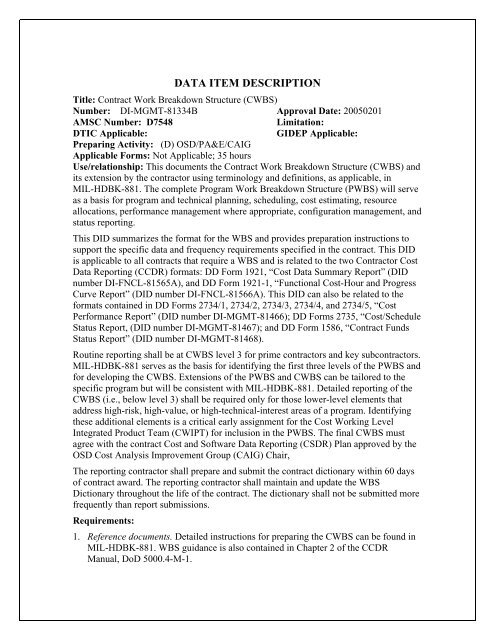
DATA ITEM DESCRIPTION<br />
Title: <strong>Contract</strong> <strong>Work</strong> <strong>Breakdown</strong> <strong>Structure</strong> (<strong>CWBS</strong>)<br />
Number: DI-MGMT-81334B Approval Date: 20050201<br />
AMSC Number: D7548 Limitation:<br />
DTIC Applicable: GIDEP Applicable:<br />
Preparing Activity: (D) OSD/PA&E/CAIG<br />
Applicable Forms: Not Applicable; 35 hours<br />
Use/relationship: This documents the <strong>Contract</strong> <strong>Work</strong> <strong>Breakdown</strong> <strong>Structure</strong> (<strong>CWBS</strong>) and<br />
its extension by the contractor using terminology and definitions, as applicable, in<br />
MIL-HDBK-881. The complete Program <strong>Work</strong> <strong>Breakdown</strong> <strong>Structure</strong> (PWBS) will serve<br />
as a basis for program and technical planning, scheduling, cost estimating, resource<br />
allocations, performance management where appropriate, configuration management, and<br />
status reporting.<br />
This DID summarizes the format for the WBS and provides preparation instructions to<br />
support the specific data and frequency requirements specified in the contract. This DID<br />
is applicable to all contracts that require a WBS and is related to the two <strong>Contract</strong>or Cost<br />
Data Reporting (CCDR) formats: DD Form 1921, “Cost Data Summary Report” (DID<br />
number DI-FNCL-81565A), and DD Form 1921-1, “Functional Cost-Hour and Progress<br />
Curve Report” (DID number DI-FNCL-81566A). This DID can also be related to the<br />
formats contained in DD Forms 2734/1, 2734/2, 2734/3, 2734/4, and 2734/5, “Cost<br />
Performance Report” (DID number DI-MGMT-81466); DD Forms 2735, “Cost/Schedule<br />
Status Report, (DID number DI-MGMT-81467); and DD Form 1586, “<strong>Contract</strong> Funds<br />
Status Report” (DID number DI-MGMT-81468).<br />
Routine reporting shall be at <strong>CWBS</strong> level 3 for prime contractors and key subcontractors.<br />
MIL-HDBK-881 serves as the basis for identifying the first three levels of the PWBS and<br />
for developing the <strong>CWBS</strong>. Extensions of the PWBS and <strong>CWBS</strong> can be tailored to the<br />
specific program but will be consistent with MIL-HDBK-881. Detailed reporting of the<br />
<strong>CWBS</strong> (i.e., below level 3) shall be required only for those lower-level elements that<br />
address high-risk, high-value, or high-technical-interest areas of a program. Identifying<br />
these additional elements is a critical early assignment for the Cost <strong>Work</strong>ing Level<br />
Integrated Product Team (CWIPT) for inclusion in the PWBS. The final <strong>CWBS</strong> must<br />
agree with the contract Cost and Software Data Reporting (CSDR) Plan approved by the<br />
OSD Cost Analysis Improvement Group (CAIG) Chair,<br />
The reporting contractor shall prepare and submit the contract dictionary within 60 days<br />
of contract award. The reporting contractor shall maintain and update the WBS<br />
Dictionary throughout the life of the contract. The dictionary shall not be submitted more<br />
frequently than report submissions.<br />
Requirements:<br />
1. Reference documents. Detailed instructions for preparing the <strong>CWBS</strong> can be found in<br />
MIL-HDBK-881. WBS guidance is also contained in Chapter 2 of the CCDR<br />
Manual, DoD 5000.4-M-1.
DI-MGMT-81334A<br />
2. Formats. The <strong>CWBS</strong> shall be reflected in an electronic report that consists of two<br />
parts as shown in the sample attachments. Part I is for the <strong>CWBS</strong> Index and Part II is<br />
for the <strong>CWBS</strong> Dictionary. The index lists the individual elements. The dictionary<br />
describes the effort and tasks associated with every <strong>CWBS</strong> element shown in Part I.<br />
Preparation Instructions:<br />
1. <strong>Contract</strong> <strong>Work</strong> <strong>Breakdown</strong> <strong>Structure</strong> Index:<br />
a. <strong>CWBS</strong> Code. Enter the code, if applicable.<br />
b. <strong>CWBS</strong> Element Level. Enter the level of the <strong>CWBS</strong> element. Level 1 is the total<br />
contract. Levels 2, 3, etc., are successively lower levels of the program.<br />
c. <strong>CWBS</strong> Element Name. Enter the title of the <strong>CWBS</strong> element using the specific<br />
name or nomenclature.<br />
d. <strong>Contract</strong> Line Item(s). Enter the numbers of the contract line items associated<br />
with the <strong>CWBS</strong> element, if applicable.<br />
2. <strong>Contract</strong> <strong>Work</strong> <strong>Breakdown</strong> <strong>Structure</strong> Dictionary:<br />
a. <strong>CWBS</strong> Code.<br />
b. <strong>CWBS</strong> Element. Enter the title of each <strong>CWBS</strong> element in the same order as given<br />
in Part I.<br />
c. <strong>CWBS</strong> Definition. Enter a complete description of the technical and cost content<br />
of each <strong>CWBS</strong> element. The statement should be as descriptive as possible about<br />
the efforts, tasks, tests, components, etc., that are to be included in the <strong>CWBS</strong><br />
element by the contractor. The <strong>CWBS</strong> Dictionary must be updated and<br />
maintained throughout the life of the contract. However, the updated dictionary<br />
shall be submitted no more frequently than the CCDR report submissions.<br />
2
3<br />
1.0<br />
1.1<br />
1.1.1<br />
1.1.2<br />
1.1.3<br />
1.1.4<br />
1.1.5<br />
1.1.5.1<br />
1.1.5.1.1<br />
1.1.5.1.2<br />
1.1.5.2<br />
1.1.5.3<br />
1.1.5.4<br />
1.1.6<br />
1.1.7<br />
1.1.8<br />
1.1.9<br />
1.1.10<br />
1.2<br />
1.3<br />
1.4<br />
CONTRACT WORK BREAKDOWN<br />
STRUCTURE INDEX<br />
<strong>CWBS</strong><br />
CODE 1<br />
�<br />
2<br />
�<br />
�<br />
�<br />
�<br />
LEVEL<br />
3 4 5<br />
�<br />
�<br />
�<br />
�<br />
�<br />
�<br />
�<br />
�<br />
�<br />
�<br />
�<br />
�<br />
�<br />
�<br />
�<br />
�<br />
PROGRAM:<br />
Missile X LRIP Surface-to-Air Interceptor<br />
<strong>CWBS</strong> ELEMENT<br />
Missile System<br />
Air Vehicle<br />
Propulsion<br />
Airframe<br />
Warhead<br />
Post Boost System<br />
Guidance And Control Equipment<br />
Guidance Section<br />
Seeker<br />
Guidance Electronics<br />
Control Devices<br />
<strong>Structure</strong><br />
Power and Networks<br />
Ordnance Initiation Set<br />
Airborne Test Equipment<br />
Airborne Training Equipment<br />
Auxiliary Equipment<br />
IAT&C<br />
Integration, Assembly, Test, and Checkout<br />
Systems Engineering/Program Management<br />
Systems Test and Evaluation<br />
NAME<br />
REP NO: XXXXXX<br />
CONTRACT NO: XXXXXX-98-C-XXX<br />
CONTRACT PLAN NO:<br />
XXXXXXXX<br />
CONTRACT LINE ITEM(S)<br />
DATE:<br />
06/30/02<br />
<strong>Contract</strong> <strong>Work</strong> <strong>Breakdown</strong> <strong>Structure</strong>—Data Item Description (DI-MGMT-81334)
CONTRACT WORK BREAKDOWN<br />
STRUCTURE DICTIONARY<br />
<strong>CWBS</strong> CODE<br />
1.0<br />
1.1<br />
1.1.1<br />
1.1.2<br />
1.1.3<br />
1.1.4<br />
1.1.5<br />
1.1.5.1<br />
1.1.5.1.1<br />
1.1.5.1.2<br />
1.1.5.2<br />
1.1.5.3<br />
1.1.5.4<br />
1.1.6<br />
1.1.7<br />
1.1.8<br />
1.1.9<br />
1.1.10<br />
Missile System<br />
Air Vehicle<br />
Propulsion<br />
Airframe<br />
Warhead<br />
Post Boost System<br />
<strong>Contract</strong> <strong>Work</strong> <strong>Breakdown</strong> <strong>Structure</strong>—Data Item Description (DI-MGMT-81334)<br />
<strong>CWBS</strong> ELEMENT<br />
Guidance and Control Equipment<br />
Guidance Section<br />
Seeker<br />
Guidance Electronics<br />
Control Devices<br />
<strong>Structure</strong><br />
Power and Networks<br />
Ordnance Initiation Set<br />
Airborne Test Equipment<br />
Airborne Training Equipment<br />
Auxiliary Equipment<br />
Integration, Assembly, Test and Checkout<br />
PROGRAM:<br />
Missile X LRIP Surface-to-Air Interceptor<br />
4<br />
RFP NO: ________________________<br />
CONTRACT NO: XXXXX-98-C-XXXX<br />
<strong>CWBS</strong> DEFINITION<br />
DATE:<br />
11/1/00<br />
The missile is a cylindrical body with four fixed fins attached to the aft end of the Solid Rocket Motor case. The<br />
control surfaces are located behind the fixed fins. The missile angular orientation is zero degrees at top center,<br />
with increasing angles positive in a clockwise direction (standing at the aft end looking forward). The outside<br />
surface of the missile body is coated for thermal protection of the structure from aerodynamic heating and rain<br />
erosion. Electrical interface between the launcher and the missile is provided by an umbilical cable connecting<br />
the missile Aft-Section to the Aft-Section of the Canister.<br />
This element refers to the means for delivering the destructive effect to the target, including the capability to<br />
generate or receive intelligence to navigate and penetrate to the target area and to detonate the warhead. This<br />
element includes the design, development, and production of complete units (prototype and operationally<br />
configured units, which satisfy the requirement of their applicable specifications(s)) regardless of their use.<br />
The propulsion system consists of the booster and the interstage. A single-stage, solid propellant rocket motor<br />
provides all of the boost impulse for the missile. The deployable flares and aft rate gyro package (RGP) are<br />
positioned at the aft end of the booster in the BUG configuration.<br />
This element refers to the structural framework that provides the aerodynamic shape, mounting surfaces and<br />
environmental protection for the missile components. It includes the wings, fins, and structural body<br />
assemblies.<br />
Warhead includes the assembly containing the kill mechanism of the round and its associated high explosives,<br />
chemicals, biological agents, nuclear devices, and pyrotechnics.<br />
This element provides the roll rate control and the final velocity to adjust and deploy the payload as well as the<br />
external protection material, velocity control system, and deployment group.<br />
This element refers to the missile’s ability to acquire and track targets, receive guidance data from various<br />
sensors and execute the necessary flight path to intercept the target.<br />
This element refers to the missile’s ability to receive guidance data from various sensors.<br />
The seeker assembly is attached to the kill vehicle via the forward ring of the forecone. The assembly consists<br />
of four elements; a seeker basecone, an IR sensor, a gimbal set, and a Seeker Electronics Assembly (SEA).<br />
The seeker basecone is a conical assembly cast from magnesium. It is used as the main structure to mount<br />
the IR sensor and gimbals to the KV, and to dampen structural resonances.<br />
This element includes all the electronic components and their structural items needed to perform all the seeker<br />
tracking functions.<br />
This element includes all the electronic components and support structure needed to perform the electronic<br />
processing done outside, but near the detector assembly. This may include detector biasing electronics,<br />
preamplification, gain control processing, A/D conversion and multiplexing of the detector outputs when many<br />
detector outputs are present.<br />
This element refers to the metal or composite materials that provide external housing, bulkheads, attach points<br />
and connectors for guidance and control equipment.<br />
This element refers to the subsystem that starts the missile and maintains electrical power prior to launch, upon<br />
release from the launch platform, and during flight. Additionally, it consists of power supply devices and power<br />
converters.<br />
The ordnance initiation set initiates all ordnance events throughout the missile and ground system (except<br />
reentry system components). Upon receipt of an electrical signal from the missile guidance and control system,<br />
the ordnance initiation set firing units convert the signal into ordnance outputs to the detonating cords. Among<br />
these ordnance events are stage separation, motor ignition, gas generator ignition, shroud separation, etc.<br />
Includes through bulkhead initiators, ordnance test harnesses, and firing units/exploding bridge wires.<br />
The airborne test equipment element refers to an exercise warhead that is interchangeable with the live<br />
warhead and suitable for developmental firing. This element includes destruct systems, recovery systems,<br />
special instrumentation, and telemetry equipment.<br />
The airborne training equipment element refers to an exercise warhead that is interchangeable with the live<br />
warhead and suitable for training firing. This element includes destruct systems, recovery systems, special<br />
instrumentation, and telemetry equipment associated with the training mission.<br />
The auxiliary equipment element refers to that additional equipment generally excluded from other specific<br />
elements. This element includes the environmental control, safety and protective subsystems, and destruct<br />
system. It also includes equipment of a single purpose and function that is necessary for accomplishing the<br />
assigned mission.<br />
The IAT&CO of the hardware will be conducted at the contractor’s assembly facility. Subsystem components<br />
will be assembled and tested, then shipped to company YYYY for final assembly and testing.
CONTRACT WORK BREAKDOWN<br />
STRUCTURE DICTIONARY<br />
<strong>CWBS</strong> CODE<br />
1.2<br />
1.3<br />
1.4<br />
<strong>Contract</strong> <strong>Work</strong> <strong>Breakdown</strong> <strong>Structure</strong>—Data Item Description (DI-MGMT-81334)<br />
<strong>CWBS</strong> ELEMENT<br />
Integration, Assembly, Test, and Checkout<br />
Systems Engineering/Program<br />
Management<br />
Systems Test and Evaluation<br />
End of DI-MGMT-81334B<br />
PROGRAM:<br />
Missile X LRIP Surface-to-Air Interceptor<br />
RFP NO: ________________________<br />
CONTRACT NO: XXXXXX-98-C-XXXX<br />
<strong>CWBS</strong> DEFINITION<br />
DATE:<br />
11/1/00<br />
The IAT&CO of the missile will be conducted at a Company YYYY assembly facility. For flight vehicles, the<br />
guidance and control unit is tested and installed, the units are fueled, and the ordinance is installed. The missile<br />
is then installed in the canister and shipped to the testing range.<br />
The system engineering and technical control as well as the business management of the project. System<br />
Engineering/Project Management effort that can be associated specifically with the hardware element is<br />
excluded, unless this management effort is of special contractual or engineering significance (e.g., associated<br />
contractor).<br />
Four prototypes of the missile will be tested at WWWW testing range over a period of 3 months. The testing<br />
facility will evaluate both missile performance and accuracy, along with the launching platform capabilities.<br />
5